1
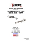
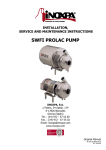
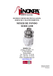
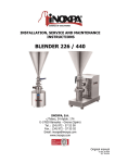
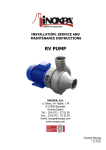
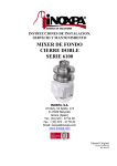
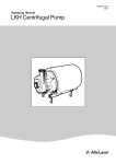
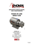
INSTALLATION, SERVICE AND
MAINTENANCE INSTRUCTIONS
MULTITOOTH MIXER
875X-892X SERIES
INOXPA, S.A.
c/Telers, 54 Aptdo. 174
E-17820 Banyoles
Girona (Spain)
Tel.: (34) 972 - 57 52 00
Fax.: (34) 972 - 57 55 02
Email: [email protected]
www.inoxpa.com
Original Manual
MIME800X_EN
ED. 2011/05
EC DECLARATION OF CONFORMITY
(In accordance with Directive 2006/42/EC, annex II, part A)
We, the manufacturer:
INOXPA, S.A.
c/ Telers, 54
17820 Banyoles (Girona) - Spain
Hereby declare that the products
MULTI-TOOTH MIXER
ME-875X / ME-895X
Name
Type
are in conformity with the provisions of the Council Directives:
Machine Directive 2006/42/EC, and comply with the essential requirements of said Directive
and the harmonised standards:
UNE-EN ISO 12100-1/2:2004
UNE-EN ISO 13857:2008
UNE-EN 953:1997
UNE-EN ISO 13732:2007
Low-Voltage Directive 2006/95/EC (what repeal 73/23/EEC Directive), and conform to UNEEN 60204-1:2006 and UNE-EN 60034-1:2004.
Electromagnetic Compatibility Directive 2004/108/EC (what repeal 89/336/EEC Directive),
and conform to UNE-EN 60034-1/A11:2004
In conformity with Regulation (CE) No. 1935/2004 on materials and objects intended to come
into contact with foodstuffs (repealing 89/109/EEC), in accordance with which the materials in
contact with the product do not transfer its constituents to the foodstuffs in quantities large
enough to put human health at risk.
Banyoles, 2012
Josep Mª Benet
Technical manager
1. Safety
1.1. INSTRUCTIONS MANUAL
This manual contains information on the receipt, installation, operation, assembly, disassembly, and maintenance of the Inline
Mixer ME-875 and ME-892X series.
The information published in the instruction manual is based on updated information.
INOXPA reserves the right to modify this instruction manual without prior notice.
1.2. START-UP INSTRUCTIONS
This instructions manual contains vital and useful information to appropriately handle and maintain your mixer.
Read these instructions carefully before starting up the mixer; become familiar with the operation and use of your mixer and
follow the instructions closely. These instructions should be kept in a safe place near the installation.
1.3. SAFETY
1.3.1 WARNING SYMBOLS
Danger in general
Danger of injury caused by rotating
equipment parts.
Electrical danger
Danger! Caustic or corrosive agents.
Danger! Suspended loads
Danger to the correct operation of the
equipment.
Commitment to safety at the workplace.
Protective goggles requirement.
1.4. GENERAL SAFETY INSTRUCTIONS
Read this instructions manual carefully before installing and starting the mixer. Contact INOXPA in
case of doubt.
1.4.1
During installation
The Technical Specifications of Chapter 8 should always be observed.
Never start up the mixer before it connecting it to the piping.
Do not start up the mixer if the mixer cover is not mounted.
Do not start up the mixer if the belt protection is not present.
Check that the motor specifications meet the requirements, especially when working under
conditions that involve the risk of explosion.
During the installation, all the electric work should be carried out by authorised personnel.
1.4.2
During operation
The Technical Specifications of Chapter 8 should always be observed. Under no circumstances can the
limit values specified be exceeded.
NEVER touch the mixer or the pipes during operation when the mixer is being used to transfer hot
fluids or when it is being cleaned.
The mixer contains moving parts. Never place your fingers inside the mixer while it is in operation.
ED. 2011/05
1.Safety
3
NEVER operate the pump with the suction and delivery valves closed.
NEVER spray the electrical motor with water. The standard protection of the motor is IP-55:
Protection against dust and sprayed water.
1.4.3
During maintenance
The Technical Specifications of Chapter 8 should always be observed.
NEVER disassemble the mixer until the pipes have been emptied. Remember that some of the fluid
will always remain in the mixer housing (when no drainage is provided). Note that the fluid may be
dangerous or very hot. Consult the regulations in effect in each country for these cases.
Do not leave parts loose on the floor.
ALWAYS disconnect the mixer from the power supply before starting maintenance work. Remove
the fuses and disconnect the cables from the motor terminals.
All electrical work should be carried out by authorised personnel.
1.4.4 Compliance with the instructions
Any non-fulfilment of the instructions may result in a risk for the operators, the environment and the machine, and may result
in the loss of your right to claim damages.
This non-fulfilment may result in the following risks:
•
Failure of important functions of the machines/plant.
•
Failure of specific maintenance and repair procedures.
•
Possibility of electric, mechanical and chemical risks.
•
Will place the environment in danger due to the release of substances.
1.4.5 Guarantee
Any warranty provided shall immediately be cancelled and void ipso jure, and INOXPA shall be compensated for any product
liability claim from third parties, if:
•
the service and maintenance work was not carried out in accordance with the service instructions, or the repair work
has not been carried out by our personnel or it has been conducted without our written authorization;
•
our equipment has been changed without prior written authorization;
•
the parts or lubricants used are not original INOXPA parts and products;
•
the materials were used incorrectly or negligently, or not in accordance with these instructions and their intended use;
The General Delivery Terms already provided also apply.
No change can be made to the equipment without prior discussion with the manufacturer. For your
safety, please use original spare parts and accessories.
The use of other parts will exempt the manufacturer from any liability.
The service terms can only be changed with prior written authorisation from INOXPA.
Please do not hesitate to contact us in case of doubts or if more complete explanations are required on specific data
(adjustments, assembly, disassembly, etc.).
4
1.Safety
ED. 2011/05
2. Contents
1.
Safety
1.1. INSTRUCTIONS Manual ................................................................................................... 3
1.2. Start-up instructions ........................................................................................................ 3
1.3. Safety ............................................................................................................................. 3
1.3.1 Warning symbols .......................................................................................................... 3
1.4. GENERAL SAFETY INSTRUCTIONS.................................................................................... 3
2.
Contents
3.
General information
3.1 Description ....................................................................................................................... 7
4.
5.
3.2
OPERATING Principle .................................................................................................... 7
3.3
Application ................................................................................................................... 7
3.4
Hygiene........................................................................................................................ 7
3.5
Construction materials................................................................................................... 7
Installation
4.1
RECEIPT OF THE MIXER................................................................................................ 8
4.2
TRANSPORT AND STORAGE .......................................................................................... 8
4.3
Location ....................................................................................................................... 9
4.4
PIPES ........................................................................................................................... 9
4.5
shut-off valve ............................................................................................................... 9
4.6
COOLANT ..................................................................................................................... 9
4.7
Electrical installation...................................................................................................... 9
Start-up
5.1
Start-up ......................................................................................................................10
6.
Operating Problems
7.
Maintenance
8.
7.1
General information .....................................................................................................12
7.2
Cleaning ......................................................................................................................12
7.3
Tightening torque ........................................................................................................13
7.4
LUBRICATION..............................................................................................................13
7.5
mixer Assembly and disassembly ..................................................................................13
Technical Specifications
8.1
Technical Specifications ................................................................................................16
8.2
WEIGHTS ....................................................................................................................16
8.3
Dimensions..................................................................................................................17
8.3.1 ME-875X MIXER DIMENSIONS ......................................................................................17
8.3.2 ME-892x MIXER DIMENSIONS ......................................................................................17
ED. 2011/05
8.4
cross-section with me-875x mixer baseplate ..................................................................18
8.5
ME-875X MIXER CROSS-SECTION .................................................................................19
8.6
ME-875X MIXER PARTS LIST ........................................................................................20
2.Contents
5
6
8.7
CROSS-SECTION WITH ME-892X MIXER BASEPLATE .................................................... 22
8.8
ME-892X MIXER CROSS-SECTION ................................................................................ 23
8.9
ME-892X MIXER PARTS LIST ....................................................................................... 24
2.Contents
ED. 2011/05
3. General information
3.1 DESCRIPTION
ME-875X and ME-892X series multitooth mixers present a bareshaft belt-driven type with axial suction and radial discharge,
and with hygienic type connections. The housing, cover, rotor, and stator are mechaned. All the parts that come into contact
with the product are manufactured from stainless steel.
These series are designed for continuous operation. The most significant constructional features of the range are:
• Operation on baseplate with belt transmission.
• Rotor-stator multitooth design.
• Hygienic mechanical seal.
• Rotor-stator adjustment by means of gauges.
This equipment is suitable for use in the food-processing industry.
3.2 OPERATING PRINCIPLE
• The rotor/stator design of the ME-875X and ME-892X series applies an extraordinary shear strength. The fluid is suctioned
by the impeller and is forced to pass through the teeth of the rotor and stator, and is sheared and reduced under great
strength until leaving the discharge outlet. The particle measurement reductions (of about 0.5 microns) require the product
to be passed through a minimum number of times to achieve homogeneous distribution of the particles in the end product.
• In many cases, it is recommended to operate with a frequency converter to ensure that it is possible to achieve a good end
product by means of this and the various gauges.
• The number of times the product must pass through the rotor/stator depends on three factors: rotor speed, rotor-stator
gap, product viscosity.
• Speed can be adjusted using a frequency converter; the rotor/stator gap can be adjusted using the gauges (supplied by
Inoxpa), and the viscosity can be adjusted with the formula or temperature.
3.3 APPLICATION
Inline mixers are suitable for particle reduction processes, dissolution, dispersion, and emulsion. Given their hygienic design,
these mixers are suitable for industries as demanding as cosmetics, food-processing, and pharmaceutical industries. They can
also be used in other types of industries such as adhesives, chemicals, paints, and plastics.
3.4 HYGIENE
In the construction of the mixer, special attention has been given to hygiene and cleaning. The number of slots and
unreachable spaces has been reduced to an absolute minimum.
The mixer can be cleaned easily and thoroughly by either of the two following methods:
•
Without disassembly, e.g. with steam or water, i.e. the so-called CIP (Cleaning In Place).
•
Easily disassembling the mixer.
See Section 7.2 "Cleaning" for information on how to properly clean the mixer and what cleaning methods and products should
be used.
3.5 CONSTRUCTION MATERIALS
All the parts of the mixer in contract with the product are manufactured in stainless steel or tasteless and odourless materials.
This makes the mixer resistant to corrosion, thereby the contamination of the mixed product is prevented.
During the manufacturing process, the materials (i.e. the parts in contact with the product) must be
checked and verified in order to ensure that they are suitable for pumping food products.
Table 3.1: Parts in contact with the product
Part
Material
Housing
Rotor
Stator
Mixer cover
Motor shaft
Impeller nut
AISI
AISI
AISI
AISI
AISI
AISI
316L
316L
316L
316L
316L
316L
(1.4404)
(1.4404)
(1.4404)
(1.4404)
(1.4404)
(1.4404)
Table 3.2: Parts that may come in contact with the product.
Part
Material
Support
ED. 2011/05
AISI 304 (1.4308)
3.General information
7
4. Installation
4.1 RECEIPT OF THE MIXER
INOXPA cannot be held responsible for the damage to the equipment during transport or unpacking.
Visually check that the packaging is not damaged.
The mixer will be accompanied by the following documents:
•
Dispatch notes.
•
Mixer Instructions and Service Manual.
•
Motor Instructions and Service Manual.
Unpack the mixer and check:
• The inline mixer suction and delivery connections, removing
the remains of any packaging materials.
• Check that the mixer and the motor have not suffered any
damage.
• If the equipment is not in good condition and/or any part is
missing, the carrier should draw up a report accordingly as
soon as possible.
4.1.1
Mixer identification
Serial number
Mixer Plate
4.2 TRANSPORT AND STORAGE
ME-875X and ME-895X mixers are often too heavy to be stored manually.
Lift the mixer as shown below:
Never lift the whole unit by
pulling the housing.
8
4.Installation
ED. 2011/05
4.3 LOCATION
•
Place the mixer as close as possible to the suction tank, and if possible below the fproduct level.
•
Place the mixer so as to allow sufficient space around it to access the mixer and the motor. (See Chapter 8 Technical
Specifications for dimensions and weight).
•
Set up the mixer on a flat, level surface.
•
The base must be rigid, horizontal, flat and vibration-proof.
Install the mixer so as to allow sufficient ventilation.
If the mixer is installed outdoors, it should be protected by a roof.
Its location should enable easy access for any inspection or maintenance operations.
4.4 PIPES
•
As a general rule, assemble the suction and discharge pipes in straight sections with as few elbows and accessories as
possible. This will reduce any pressure drops resulting from friction.
•
Ensure that the mixer openings are properly lined up with the piping and that the diameters between the two are
similar.
•
Place the mixer as close as possible to the suction tank, if possible below the fluid level, or even below the tank, to
achieve the maximum static suction head.
•
Place pipe supports as close as possible to the mixer’s suction inlet and delivery outlet.
4.5 SHUT-OFF VALVE
The mixer can be isolated for maintenance purposes. To this end, shut-off valves should be fitted to the pump’s suction and
delivery connections.
4.6 COOLANT
In models with a single mechanical seal with quench, it is necessary to connect the quench with water to the inlet at ambient
temperature (20oC) without pressure ~(max. 0.5 bars) and outlet in the upper atmospheric section.
ALWAYS connect the cooling fluid inlet to the lower connection of the seal chamber. Therefore, the
suction will be connected to the upper part. See mixer dimensions.
4.7 ELECTRICAL INSTALLATION
The connection of the electrical motors must be performed by qualified personnel.
Take all necessary measures to prevent damage to connections and cables.
The electrical equipment, terminals and components of the control systems may still contain electric
current when switched off. Contact with them may be dangerous for operators or cause irreversible
damage to the equipment.
•
•
Connect up the motor following the manufacturer’s instructions.
Check the direction of rotation (see the label on the mixer).
Never start up the mixer if the rotor is attached and the cover is not.
Start up the mixer briefly. Look
at the mixer from the rear to
ensure that the rotation direct is
correct: Anti-clockwise for ME875X and clockwise for the ME892X model.
ME-892 (clockwise)
ME-875X (anti-clockwise)
ALWAYS check the direction of rotation of engine with product inside the mixer.
For models with a seal chamber, ALWAYS make sure that the chamber is full of product before
checking the rotation direction.
ED. 2011/05
4.Installation
9
5. Start-up
Before starting up the multitooth mixer, thoroughly read the instructions in Chapter 4. Installation.
5.1 START-UP
Read Chapter 8 Technical Specification thoroughly. INOXPA cannot be held responsible for the incorrect
use of the equipment.
NEVER touch the mixer or the pipes when hot product is being pumped.
Do not start up the mixer if the belt protections are not in place.
5.1.1
Checks before starting up the mixer
• Fully open the shut-off valves on the suction and delivery pipes.
• If the product does not flow towards the mixer, use a feeding pump. The Inline mixer can overcome a limited discharge
pressure. The same feeding pump can be used to overcome any high discharge pressure.
• In the case of highly viscous products, also use a positive-displacement feeding pump.
The mixer must NEVER be run dry.
• Check that the motor’s direction of rotation is correct.
5.1.2
Checks when starting up the mixer
•
•
•
•
that the mixer is not making any unusual noises.
whether the absolute inlet pressure is enough to avoid cavitation in the mixer.
the flow pressure.
that there are no leaks through the sealed areas.
Check
Check
Check
Check
A shut-off valve on the suction pipe must not be used to regulate flow. Shut-off valves must be fully
open during operation.
Check the motor’s power consumption to avoid electric overload.
Reduce the flow and the power consumed by the motor:
• Regulating the flow to the pump delivery.
• Decreasing motor speed.
10
5.Start-up
ED. 2011/05
6. Operating Problems
The following table provides solutions to problems that might arise during mixer operation. The mixer is assumed to have been
properly installed and correctly selected for the application.
Please contact INOXPA if technical assistance is required.
Operating Problems
Probable causes
Motor overload
The mixer does not provide enough flow or pressure
No pressure on the delivery side
Uneven delivery flow / pressure
Noise and vibration
The mixer becomes jammed.
Mixer becomes overheated.
Abnormal wear
The mechanical seal is leaking.
Insufficient mixture
8, 12.
1, 2, 3, 4, 6, 8, 9, 14.
2, 5, 15.
1, 3, 4, 5, 8.
3, 4, 5, 6, 8, 9, 12, 13, 17.
8, 9, 12.
8, 9, 12
3, 4, 9, 16, 17.
10, 11, 16.
1, 2, 3, 4, 5, 6, 7, 8, 14.
Probable causes
Solutions
1
2
3
4
5
6
Wrong direction of rotation
The fluid does not flow towards the mixer
Cavitation
The mixer is sucking air.
Clogged suction tube
Delivery pressure too high
7
Insufficient recirculation of the product by the mixer
8
Product viscosity too high
9
10
11
12
Fluid temperature too high
Mechanical seal damaged or worn.
O-rings unsuitable for the product.
The impeller scrapes.
13
14
15
16
17
Tension in the pipes
Mixer speed too low.
The cut-off valve on the suction side is closed
Inappropriate materials
Foreign particles in the product
Change the direction of rotation, exchanging 2 phases.
Use a feeding pump
Increase the suction pressure or use a feeding pump.
Check the suction pipe and all its connections
Check the suction pipe and all its filters
If necessary, reduce pressure drops, e.g. by increasing the
diameter of the pipe
Increase shearing by means of the gauges by reducing the
number of passes between the rotor-stator or increase speed (see
technical characteristics)
Reduce viscosity by injecting liquid, increasing temperature, or
using a feeding pump.
Reduce the temperature by cooling the product.
Replace the seal
Fit suitable O-rings after consulting the supplier.
- Reduce temperature
- Reduce suction pressure
Connect the piping to the mixer without tension.
Increase speed.
Check and open
Check with the Technical Dep.
Fit a filter to the suction pipe
If the problems persists, stop using the mixer immediately. Contact the mixer manufacturer or its
representative.
ED. 2011/05
6.Operating Problems
11
7. Maintenance
7.1 GENERAL INFORMATION
Like any other machine, this mixer requires maintenance. The instructions contained in this manual cover the identification and
replacement of spare parts. The instructions have been prepared for maintenance personnel and for those responsible for the
supply of spare parts.
Please thoroughly read Chapter 8 Technical Specification.
All replaced material should be duly eliminated/recycled according to the directives in effect in the
area.
ALWAYS disconnect the mixer from the power supply before undertaking maintenance work.
7.1.1 Check the mechanical seal and the retainer
Regularly check that there are no leaks in the shaft area. If there are leaks through the mechanical seal or the retainer, replace
it following the instructions given under the Disassembly and Reassembly section.
Verifying the tightness of the seal and the retainer is of the utmost importance. Since this would be
an internal leak, it is difficult to detect.
7.2 CLEANING
The use of aggressive cleaning products such as caustic soda and nitric acid may cause burns to the
skin.
Use rubber gloves during the cleaning process.
Always use protective goggles.
7.2.1
Automatic CIP (cleaning-in-place)
If the mixer is installed in a system with a CIP process, it is not necessary to dismantle the mixer.
If there is no automatic cleaning process, dismantle the mixer as indicated in the Assembly and Disassembly section.
Cleaning solutions for CIP processes.
Only use clear water (chlorine-free) to mix with the cleaning agents:
a) Alkaline solution:
1% by weight of caustic soda (NaOH) at 70ºC (150ºF)
1 Kg NaOH + 100 l. of water = cleaning solution
o
2.2 l. NaOH at 33% + 100 l. of water = cleaning solution
b) Acid solution:
0.5% by weight of nitric acid (HNO3) at 70ºC (150ºF)
0.7 litres HNO3 at 53% + 100 l. of water = cleaning
Check the concentration of cleaning solutions; it may cause the deterioration of the watertight seals
of the mixer.
12
7.Maintenance
ED. 2011/05
To remove any remains of cleaning products, ALWAYS perform a final rinse with clean water on completion of the cleaning
process.
7.2.2
Automatic SIP (sterilization-in-place)
The process of sterilization with steam is applied to all the equipment including the pump.
Do NOT start the pump during the process of sterilization with steam.
The parts/materials suffer no damage if the indications specified in this manual are observed.
No cold liquid can enter the pump till the temperature of the pump is lower than 60°C (140°F).
A flow by-pass is recommended to be used in order to assure the flow of sterile product after the
pump.
Maximum conditions during the SIP process with steam or overheated water
a)
b)
c)
d)
Max. temperature:
Max. time:
Cooling:
Materials:
140°C / 284°F
30 min
Sterile air or inert gas
EPDM / PTFE (recommended)
FPM / NBR (not recommended)
7.3 TIGHTENING TORQUE
Material
Torque value [N.m.]
M5
M6
M8
M10
M12
M14
M16
M18
M20
8.8
6
10
25
49
86
135
210
290
410
A2
5
9
21
42
74
112
160
210
300
7.4 LUBRICATION
The bearings are lubricated by means of an oil bath.
The mixer is supplied with oil.
• Check the oil level regularly, e.g. weekly or after every 150 hours of service.
• The first oil change should be conducted after 150 hours of service.
• Following this, the oil should be changed after every 2,500 hours of service or at least once a year under normal operating
conditions.
When the oil is changed. the oil box should be filled up to the level in the centre of the sight-glass.
Do not overfill the support with oil.
Leave the mixer in the stop position for a while and then check the oil level; if necessary, add a little more oil.
Oil for ambient temperatures of 5 to 50°C: ISO VG 10.
TYPE
MIXER
Support oil
capacity [l.]
ME-875X
0.5
ME-892X
1.5
7.5 MIXER ASSEMBLY AND DISASSEMBLY
7.5.1 Mixer housing and stator 875X-892X
Disassembly
Close the suction and delivery valves.
Disconnect the cooling circuit from the mixer.
Remove the mixer from the place of installation.
Clean and dry the mixer.
Caution: liquid may spill out when removing the mixer housing.
ED. 2011/05
7.Maintenance
13
Remove the Allen screws (51B in 875X or 51A in 892X) fastening the housing cover (02) to the housing (01).
Remove the housing cover assembly (03), spacer washer (35), stator (22), and O-ring (80B), and to this end, place two of the
Allen screws (51B in 875X or 51A in 892X) in the threaded openings of the housing cover (03).
Once fitted, screw them in; these will tighten the housing and axially displace the entire assembly mentioned above.
Remove the Allen screws (51C in 875X or 51A in 892X) fastening the housing cover (03), spacer washer (35), and stator (22).
Note: There are three different spacers (35) (thicknesses of 0.5, 1, 1.5 mm for the ME-892X model and
thicknesses 0.3, 0.45, and 0.6 mm for the ME-875X model) suitable for different processes. These are marked
by laser to indicate the distance of the gap between the rotor (21) and the stator (22).
Remove the O-ring (80B) from the stator (22).
Remove the housing (02) by taking out the Allen screws (51 in 875X or 51C in 892X).
Assembly
Place the O-ring (80B) on the stator (22).
Take the spacer washer (35) adapted to the process and insert it into the stator (22), then fasten the aforementioned parts to
the housing cover (03) using the Allen screws (51C in 875X or 51A in 892X).
Attach the housing (01) to the cooling flange (10) by fastening it with the Allen screws (51 in 875X or 51C in 892X).
CAUTION! Take care to assemble the parts and seals with soapy water to enable them to slide easily.
Attach the housing cover assembly (03), spacer washer (35), and stator (22) to the housing by fitting 4 distributed threaded
rods and tighten the assembly using nuts until coming into contact with the housing (03).
CAUTION! Do not insert the aforementioned assembly using a plastic hammer, as this could damage
the stator teeth (22).
7.5.2
Single mechanical seal
Disassembly 875X
Remove the nut (45) and seal (80C), and place a fixed wrench between the pulley protection (48) and the drive key-hole (93)
(to prevent the pulleys from turning). And use the other wrench to unscrew the nut (45).
Remove the rotor (21) and the rotary part of the seal (08) by loosening its setbolts.
Remove the cover (09) and the fixed part of the seal (08).
Remove the O-ring (80B).
Disassembly 892X
Remove the nut (45) and seal (80C), and place a fixed wrench between the pulley protection (48) and the drive key-hole (93)
(to prevent the pulleys from turning). And use the other wrench to unscrew the nut (45).
Remove the rotor (21) and the rotary part of the seal (08).
Remove the cover (09) and the fixed part of the seal (08) remove the seal spring of the cover (09) by turning it with the knobs.
Remove the O-ring (80B).
Assembly 875X
Insert the O-ring (80B) into the seal cover (09).
Insert the rotary part of the seal (08) on the shaft (05).
Then place the fixed part of the seal, ensuring that the knob of the seal cover (09) is lined up with the milling of the seal; to
this end, manually press the rotary part of the seal using a plastic, PVC, PTFE buffer on the part that is in contact with the
polished surface.
Assembly 892X
Insert the O-ring (80B) into the seal cover (09).
Place the seal spring (08) on the seal cover (09) using its knobs.
Then place the fixed part of the seal ensuring that the knob of the seal cover (09) is lined up with the milling of the seal.
Insert the rotary part of the seal (08) into the rotor (21); to this end, manually press the rotary part of the seal using a plastic,
PVC, PTFE buffer on the part that is in contact with the polished surface. See illustration. 7.1.
Fig. 7.1
14
7.Maintenance
ED. 2011/05
CAUTION! When placing the new seal, take care to assemble the parts and seals using soapy water to ensure
that these slide over each other, including the stationary part and the rotary part.
Insert the rotor (21) over the shaft (05) lining up the fittings of the rotor and shaft.
Place the seal (80C) on the nut (45) and screw the nut onto the shaft (05) while preventing the pulleys from turning.
Fasten the setbolts of the rotary part of the seal (08).
7.5.3
PTFE retainer for 875X-892X
Disassembly
Remove the cooled flange (10) from the support by taking out the Allen screws (51 in 875X and 51C in 892X) from the housingside leg (07A).
Remove the O-ring (80ª) and PTFE retainer (88ª) from their housing using a plastic hammer.
Remove the connectors (92 and 92A).
CAUTION! Before fitting the retainer, check that the surface in the area of the mixer shaft (05) has a ground
finish.
Assembly
Place the connectors (92 and 92A) and the O-ring (80B) on the cooled flange (10).
Place the lip retainer (88ª) on the cooled flange (10) ensuring that the lip is correctly positioned. See fig. 7.2
Fig. 7.2
Attach the cooled flange (10) to the support (06) using Allen screws (51 in 875X and 51C in 892X).
7.5.4
875X-892X belts
Disassembly
Unscrew the belt protection (48).
Loosen the screw from the slide rail (38A) to bring the drive (93) closer to the support and be able to remove the belts (105).
Remove the pulleys from the drive (104A) and the mixer (104).
Assembly
Place the pulley (104A) into the drive (93) and fasten tightly the Allen screws with the Taper lock (according to the torque
stated by the manufacturer, then fit the pulley (104) to the mixer shaft (05), mount the belts onto the pulleys by reducing the
distance between the motor shaft and the mixer - the drive shafts and mixer shafts must be parallel and the pulleys aligned by
their faces (use a stiff steel ruler to check) - fasten tightly the taper lock of the pulley (104A), tighten the belts using the screws
of the slide rail (38A) and check alignment.
CAUTION! It is essential that the pulleys be perfectly aligned; otherwise, the side faces of the belts will
suffer from wear.
ED. 2011/05
7.Maintenance
15
8. Technical Specifications
8.1 TECHNICAL SPECIFICATIONS
Maximum output .....................................................................
Maximum differential pressure .................................................
Maximum suction pressure ......................................................
Operating temperature ...........................................................
Maximum speed......................................................................
Suction / delivery connections
ME-875X
3 m3/h *
1 bar (14.5 PSI)
3 bar (43.5 PSI)
-10ºC to +100ºC (EPDM)
57ºF to 212ºF (EPDM)
12,000 min-1 *
Clamp (standard)
ME-892X
8m3/h *
1 bar (14.5 PSI)
3 bar (43.5 PSI)
-10ºC to +100ºC (EPDM)
57ºF to 212ºF (EPDM)
6000 min-1 *
Clamp (standard)
* These values are presented as a guideline and will vary according to the product. Check with the Technical
Dept.
Use special protection when the noise level in the operation area exceeds 85 dB(A).
Materials
Parts in contact with the product
Other parts in stainless steel
Seals in contact with the product
Other materials for optional gaskets
Surface finish
AISI 316L
AISI 304
EPDM (standard)
Check with the supplier
Standard polishing
Mechanical seal
Type of seal ...........................................................................
Single interior seal
Cooled mechanical seal
Maximum pressure ..................................................................
0.5 bar (7.2 PSI)
Consumption ..........................................................................
2.5-5 l/min
Type of mechanical seal
Mechanical seal
materials
Single interior
Stationary part
Graphite
Rotary part
Silicon carbide
Motor
Motor according to IEC B3 standards (feet)
2 poles (2900/3500 min-1 at 50/60 Hz)
Shield ....................................................................................
Connection ............................................................................
IP55
3~, 50Hz, 380-420VΔ/660-690VY
8.2 WEIGHTS
Mixer
ME-875X
ME-892X
16
Power
Speed
-1
Weight
[kW]
[min ]
[Kg]
7.5
9.2
2900
2900
134
120
8.Technical Specifications
ED. 2011/05
8.3 DIMENSIONS
8.3.1 ME-875X MIXER DIMENSIONS
8.3.2
TYPE
DNa
DNi
DNp
A
B
C
D
E
F
G
ME-875X
1”
1”
¾”
75
494
740
24
228
252
467.5
ME-892X MIXER DIMENSIONS
TYPE
DNa
DNi
DNp
A
B
C
D
E
F
G
ME-892X
1 ½”
1 ½”
¾”
87
500
750
125
300
425
465
Dimensions with CLAMP connections
I = coolant inlet (8x6 pipe)
O = coolant outlet (8x6 pipe)
ED. 2011/05
8.Technical Specifications
17
8.4 CROSS-SECTION WITH ME-875X MIXER BASEPLATE
18
8.Technical Specifications
ED. 2011/05
8.5 ME-875X MIXER CROSS-SECTION
ED. 2011/05
8.Technical Specifications
19
8.6 ME-875X MIXER PARTS LIST
Position
20
Description
Quantity
Material
01
Housing
1
AISI 316L
03
Body cap
1
AISI 316L
05
Shaft
1
AISI 316L
06
Bearing support
1
AISI 304
07
Housing leg
1
AISI 304
07B
Non-vibratory foot
4
-
08
Mechanical seal
1
Graph/silicon/EPDM
09
Seal cover
1
AISI 316L
10
Seal cooling flange
1
AISI 316
12
Bearing casing
1
AISI 304
12A
Front bearing cover
1
AISI 304
12B
Rear bearing cover
1
AISI 304
21
Rotor
1
AISI 316L
22
Stator
1
AISI-316L
35
0.3 spacer washer
1
AISI -304
35A
0.45 spacer washer
1
AISI-304
35B
0.6 spacer washer
1
AISI -304
38
Baseplate
1
AISI -304
38A
Slide rail
2
GG-18
45
Cap nut
1
AISI -316
48
Pulley protection
1
AISI -316
51
Allen screw
14
A-2
51A
Allen screw
22
A-2
51B
Allen screw
3
A-2
51C
Allen screw
3
A-2
52
Hexagonal screw
6
A-2
52A
Hexagonal screw
4
A-2
53
Flat washer
6
A-2
53A
Flat washer
8
A-2
54
Nut
4
A-2
61
Key
1
AISI -304
61A
Key
1
AISI -304
62
Safety nut
1
Steel
63
Safety washer
1
Steel
70
Bearings
2
Steel
80
O-ring
1
Viton
80A
O-ring
1
Viton
80B
O-ring
2
EPDM
80C
O-ring
1
EPDM
81
Paper seal
1
Paper
81A
Paper seal
1
Paper
85
Oil stopper
1
AISI 303
86
Sight-glass
1
Plastic
87
Oil stopper
1
Plastic
88
Retainer
2
FPM
8.Technical Specifications
ED. 2011/05
Position
Description
Quantity
Material
88A
Retainer
1
FPM
88B
Retainer
1
PTF
91
Clamp
1
AISI -316
91A
Clamp gasket
1
EPDM
91B
Clamp blind bushing
1
AISI 316
92
Elbow connector
1
AISI 316
Connector
1
AISI 316
93
Motor
1
-
104
Driven pulley
1
GG-18
Driven pulley
1
GG-18
Belts
1
-
92A
104A
105
ED. 2011/05
8.Technical Specifications
21
8.7 CROSS-SECTION WITH ME-892X MIXER BASEPLATE
22
8.Technical Specifications
ED. 2011/05
8.8 ME-892X MIXER CROSS-SECTION
ED. 2011/05
8.Technical Specifications
23
8.9 ME-892X MIXER PARTS LIST
Position
Quantity
Material
01
Housing
1
AISI 316L
03
Body cap
1
AISI 316L
05
Shaft
1
AISI 316L
06
Bearing support
1
AISI 304
07
Motor-side leg
1
AISI 304
07A
Housing-side leg
1
AISI 304
07B
Non-vibratory foot
4
-
08
Mechanical seal
1
Graph/silicon/EPDM
09
Seal cover
1
AISI 316L
10
Seal cooling flange
1
AISI 316
12
Bearing casing
1
AISI 304
12A
Front bearing cover
1
AISI 304
12B
Rear bearing cover
1
AISI 304
13
Speedi-Sleeve
3
AISI 304
21
Rotor
1
AISI 316L
22
Stator
1
AISI-316L
35
0.5 spacer washer
1
AISI -304
35A
1 spacer washer
1
AISI-304
35B
1.5 spacer washer
1
AISI -304
38
Baseplate
1
AISI -304
38A
Slide rail
2
GG-18
45
Cap nut
1
AISI -316
48
Pulley protection
1
AISI -316
51
Allen screw
14
A-2
51A
Allen screw
22
A-2
51B
Allen screw
3
A-2
51C
Allen screw
3
A-2
61
Key
1
AISI -304
61A
Key
1
AISI -304
62
Safety nut
1
Steel
63
Safety washer
1
Steel
70
Bearings
2
Steel
80
O-ring
1
Viton
80A
O-ring
1
Viton
80B
O-ring
2
EPDM
80C
O-ring
1
EPDM
80D
O-ring
1
EPDM
85
Oil stopper
1
AISI 303
86
Sight-glass
1
Plastic
87
Oil stopper
1
Plastic
88
Retainer
2
Viton
88A
Retainer
1
PTFE
Clamp
1
AISI -316
91A
Clamp gasket
1
EPDM
91B
Clamp blind bushing
1
AISI 316
91
24
Description
8.Technical Specifications
ED. 2011/05
Position
Quantity
Material
Elbow connector
1
AISI 316
Connector
1
AISI 316
93
Motor
1
-
104
Driven pulley
1
GG-18
92
92A
Description
104A
Driven pulley
1
GG-18
105
Belts
1
-
ED. 2011/05
8.Technical Specifications
25
INOXPA, S.A.
c/ Telers, 54 – PO Box 174
17820 BANYOLES (GIRONA)
DELEGACIÓN NORD-ESTE /
Ó DEL VALLÈS (BCN)
BARBERÀ
Tel: 937 297 280
Fax: 937 296 220
e-mail: [email protected]
ZARAGOZA
Tel: 976 591 942
Fax: 976 591 473
e-mail: [email protected]
DELEGACIÓN LEVANTE
PATERNA (VALENCIA)
Tel: 963 170 101
Fax: 963 777 539
e-mail: [email protected]
DELEGACIÓN CENTRO
ARGANDA DEL REY (MADRID)
Tel: 918 716 084
Fax: 918 703 641
e-mail: [email protected]
DELEGACIÓN STA
GALDACANO (BILBAO)
Tel: 944 572 058
Fax: 944 571 806
e-mail: [email protected]
LA CISTÉRNIGA (VALLADOLID)
Tel: 983 403 197
Fax: 983 402 640
e-mail: [email protected]
LOGROÑO
Tel: 941 228 622
Fax: 941 204 290
e-mail: [email protected]
INOXPA SOLUTIONS LEVANTE
PATERNA (VALENCIA)
Tel: 963 170 101
Fax: 963 777 539
e-mail: [email protected]
INOXPA SOLUTIONS FRANCE
GLEIZE
Tel: 33 474627100
Fax: 33 474627101
e-mail: [email protected]
CHAMBLY (PARIS)
Tel: 33 130289100
Fax: 33 130289101
e-mail: [email protected]
ST. SEBASTIEN sur LOIRE
Tel/Fax: 33 130289100
e-mail: [email protected]
WAMBRECHIES
Tel: 33 320631000
Fax: 33 320631001
e-mail: [email protected]
INOXPA AUSTRALIA PTY (LTD)
MORNINGTON (VICTORIA)
Tel: 61 3 5976 8881
Fax: 61 3 5976 8882
e-mail: [email protected]
INOXPA ALGERIE
ROUIBA
Tel: 213 21856363 / 21851780
Fax: 213 21854431
e-mail: [email protected]
INOXPA SOUTH AFRICA (PTY) LTD
JOHANNESBURG
Tel: 27 117 945 223
Fax: 27 866 807 756
e-mail: [email protected]
INOXPA USA, Inc
SANTA ROSA
Tel: 1 7075 853 900
Fax: 1 7075 853 908
e-mail: [email protected]
INOXPA UK LTD
SURREY
Tel: 44 1737 378 060 / 079
Fax: 44 1737 766 539
e-mail: [email protected]
S.T.A. PORTUGUESA LDA
VALE DE CAMBRA
Tel: 351 256 472 722
Fax: 351 256 425 697
e-mail: [email protected]
INOXPA ITALIA, S.R.L.
BALLO DI MIRANO – VENEZIA
Tel: 39 041 411 236
Fax: 39 041 5128 414
e-mail: [email protected]
INOXPA SKANDINAVIEN A/S
HORSENS (DENMARK)
Tel: 45 76 286 900
Fax: 45 76 286 909
e-mail: [email protected]
IMPROVED SOLUTIONS
VALE DE CAMBRA
Tel: 351 256 472 140 / 138
Fax: 351 256 472 130
e-mail: [email protected]
INOXPA INDIA PVT. LTD.
Maharashtra, INDIA.
Tel: 91 2065 008 458
Tel: 34 972575200
Fax: 34 972575502
e-mail: [email protected]
www.inoxpa.com
INOXPA SPECIAL PROCESSING
EQUIPMENT, CO., LTD.
JIAXING (China)
Tel.: 86 573 83 570 035 / 036
Fax: 86 573 83 570 038
INOXRUS
MOSCOW (RUSIA)
Tel / Fax: 74 956 606 020
e-mail: [email protected]
INOXPA WINE SOLUTIONS
VENDARGUES (FRANCE)
Tel: 33 971 515 447
Fax: 33 467 568 745
e-mail: [email protected] /
INOXPA UCRANIA
KIEV
Tel: 38 050 720 8692
e-mail: [email protected]
DELEGACIÓN SUR
JEREZ DE LA FRONTERA (CÁDIZ)
Tel / Fax: 956 140 193
e-mail: [email protected]
[email protected]
SAINT PETERSBURG (RUSIA)
Тel: 78 126 221 626 / 927
Fax: 78 126 221 926
e-mail: [email protected]
[email protected]
In addition to our branch offices, INOXPA operates with an independent distributor network which encompasses a total of more than 50
countries throughout the world.
For more information consult our web page:
www.inoxpa.com
This information is a guideline only. We reserve the right to modify any material or characteristic without prior notice.