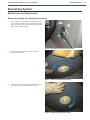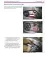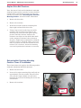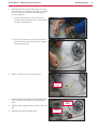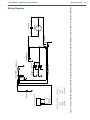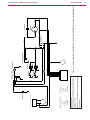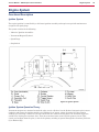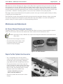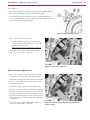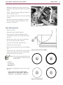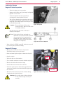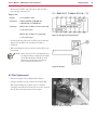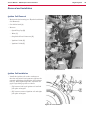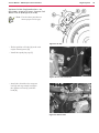
1
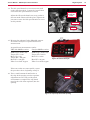
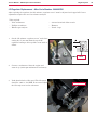
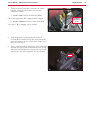
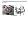
PBU Propane Floor Burnisher
21KB
21KBCAT
21KBCATCL
27KB
27KBCL
27KBCAT
21KBCATCLST
21KBCATCLFC27KBCATCLDC
MPS-1721
MPS-1727
Service Manual
Nilfisk-Advance “PBU” Machines: 56381402, 56381404, 56381405, 56381406, 56381407,
56381408 (Dust control unit), 56381409 (Dust control unit), 56381454
Nilfisk-Advance “Propane Stripper” Machine: 56381410
Diamatic Machines: 56381412, 56381413
English
03/11 Revised 07/12 Form No. 56043153
Service Manual: PBU Floor Burnisher
Contents
General Information . . . . . . . . . . . . . . . . . . . . . . . . . . . . . . . . . . . . . . . . . . 4
Service Manual Purpose and Application . . . . . . . . . . . . . . . . . . . . . . . . . . . 4
Document Revision History . . . . . . . . . . . . . . . . . . . . . . . . . . . . . . . . . . . 4
Other Reference Manuals . . . . . . . . . . . . . . . . . . . . . . . . . . . . . . . . . . . . 4
Conventions . . . . . . . . . . . . . . . . . . . . . . . . . . . . . . . . . . . . . . . . . . . 4
Transporting the Machine . . . . . . . . . . . . . . . . . . . . . . . . . . . . . . . . . . . 5
Cautions and Warnings . . . . . . . . . . . . . . . . . . . . . . . . . . . . . . . . . . . . . 5
General Machine Description . . . . . . . . . . . . . . . . . . . . . . . . . . . . . . . . . 7
Nameplate . . . . . . . . . . . . . . . . . . . . . . . . . . . . . . . . . . . . . . . . . . . . 8
Operator Controls . . . . . . . . . . . . . . . . . . . . . . . . . . . . . . . . . . . . . . . . 8
Know Your Machine — Major components: . . . . . . . . . . . . . . . . . . . . . . . . . . 9
Specifications . . . . . . . . . . . . . . . . . . . . . . . . . . . . . . . . . . . . . . . . . 10
Maintenance Schedule . . . . . . . . . . . . . . . . . . . . . . . . . . . . . . . . . . . . 13
Burnishing System . . . . . . . . . . . . . . . . . . . . . . . . . . . . . . . . . . . . . . . . . . 14
Maintenance and Adjustments . . . . . . . . . . . . . . . . . . . . . . . . . . . . . . . . 14
Replace burnishing disc pad gripper assembly. . . . . . . . . . . . . . . . . . . . . . . .
Replace Burnishing Disc Assembly Drive Belt. . . . . . . . . . . . . . . . . . . . . . . . .
Replace Drive Belt Tensioner. . . . . . . . . . . . . . . . . . . . . . . . . . . . . . . . . .
Relocating Belt Tensioner Mounting Position - Some 27 Inch Models . . . . . . . . . . .
Replace Drive Clutch . . . . . . . . . . . . . . . . . . . . . . . . . . . . . . . . . . . . .
14
15
16
16
18
Electrical System . . . . . . . . . . . . . . . . . . . . . . . . . . . . . . . . . . . . . . . . . . . 19
Functional Description . . . . . . . . . . . . . . . . . . . . . . . . . . . . . . . . . . . . 19
Carb Gard . . . . . . . . . . . . . . . . . . . . . . . . . . . . . . . . . . . . . . . . . . . 19
Carb Gard Normal Operation . . . . . . . . . . . . . . . . . . . . . . . . . . . . . . . . . 19
Component Locations . . . . . . . . . . . . . . . . . . . . . . . . . . . . . . . . . . . . . 20
Troubleshooting . . . . . . . . . . . . . . . . . . . . . . . . . . . . . . . . . . . . . . . . 20
Oxygen Sensor Test . . . . . . . . . . . . . . . . . . . . . . . . . . . . . . . . . . . . . . 20
Wiring Diagrams . . . . . . . . . . . . . . . . . . . . . . . . . . . . . . . . . . . . . . . . 22
Engine System . . . . . . . . . . . . . . . . . . . . . . . . . . . . . . . . . . . . . . . . . . . . 24
Functional Description . . . . . . . . . . . . . . . . . . . . . . . . . . . . . . . . . . . . 24
Ignition System . . . . . . . . . . . . . . . . . . . . . . . . . . . . . . . . . . . . . . . . . 24
Ignition System Operation Theory . . . . . . . . . . . . . . . . . . . . . . . . . . . . . . 24
Maintenance and Adjustments . . . . . . . . . . . . . . . . . . . . . . . . . . . . . . . . 25
Air Cleaner Element Cleaning and Inspection . . . . . . . . . . . . . . . . . . . . . . . .
Engine Top End Cylinder Head Inspection . . . . . . . . . . . . . . . . . . . . . . . . . .
Engine Top End, Cylinder Head Cleaning . . . . . . . . . . . . . . . . . . . . . . . . . . .
Engine Top End, Cylinder Head Assembly Removal . . . . . . . . . . . . . . . . . . . . .
Engine Top End, Cylinder Head Assembly Installation . . . . . . . . . . . . . . . . . . .
Engine Top End, Valve Clearance Inspection . . . . . . . . . . . . . . . . . . . . . . . . .
Valve Clearance Adjustment . . . . . . . . . . . . . . . . . . . . . . . . . . . . . . . . .
Valve Seat Inspection . . . . . . . . . . . . . . . . . . . . . . . . . . . . . . . . . . . . .
Lubrication System . . . . . . . . . . . . . . . . . . . . . . . . . . . . . . . . . . . . . . .
Engine Oil Level Inspection . . . . . . . . . . . . . . . . . . . . . . . . . . . . . . . . . .
Engine Oil Change . . . . . . . . . . . . . . . . . . . . . . . . . . . . . . . . . . . . . . .
Oil Filter Replacement . . . . . . . . . . . . . . . . . . . . . . . . . . . . . . . . . . . . .
Form Number 56043153
25
25
26
26
28
29
30
31
32
32
32
33
Page ii
Service Manual: PBU Floor Burnisher
Electrical System . . . . . . . . . . . . . . . . . . . . . . . . . . . . . . . . . . . . . . . .
Spark Plug Cleaning and Inspection . . . . . . . . . . . . . . . . . . . . . . . . . . . . .
Air Cleaner . . . . . . . . . . . . . . . . . . . . . . . . . . . . . . . . . . . . . . . . . . .
Element Removal . . . . . . . . . . . . . . . . . . . . . . . . . . . . . . . . . . . . . . .
Element Installation . . . . . . . . . . . . . . . . . . . . . . . . . . . . . . . . . . . . . .
Element Cleaning and Inspection . . . . . . . . . . . . . . . . . . . . . . . . . . . . . .
34
34
35
35
36
36
Troubleshooting . . . . . . . . . . . . . . . . . . . . . . . . . . . . . . . . . . . . . . . . 37
Compression Measurement . . . . . . . . . . . . . . . . . . . . . . . . . . . . . . . . . . 37
Engine Troubleshooting Guide . . . . . . . . . . . . . . . . . . . . . . . . . . . . . . . . 39
Starter Motor Troubleshooting Guide . . . . . . . . . . . . . . . . . . . . . . . . . . . . 43
Removal and Installation . . . . . . . . . . . . . . . . . . . . . . . . . . . . . . . . . . . 44
Ignition Coil Removal . . . . . . . . . . . . . . . . . . . . . . . . . . . . . . . . . . . . .
Ignition Coil Installation . . . . . . . . . . . . . . . . . . . . . . . . . . . . . . . . . . .
Spark Plug Removal . . . . . . . . . . . . . . . . . . . . . . . . . . . . . . . . . . . . . .
Spark Plug Installation . . . . . . . . . . . . . . . . . . . . . . . . . . . . . . . . . . . .
Spark Plug Cleaning and Inspection . . . . . . . . . . . . . . . . . . . . . . . . . . . . .
Spark Plug Gap Inspection . . . . . . . . . . . . . . . . . . . . . . . . . . . . . . . . . .
LP Regulator Replacement Before Serial Number 3000083761 . . . . . . . . . . . . . .
LP Regulator Replacement - After Serial Number 3000083760 . . . . . . . . . . . . . .
Replace Engine . . . . . . . . . . . . . . . . . . . . . . . . . . . . . . . . . . . . . . . . .
44
44
46
46
46
46
47
52
54
Specifications . . . . . . . . . . . . . . . . . . . . . . . . . . . . . . . . . . . . . . . . . 55
Engine Specifications . . . . . . . . . . . . . . . . . . . . . . . . . . . . . . . . . . . . . 55
Ignition Coil Specifications . . . . . . . . . . . . . . . . . . . . . . . . . . . . . . . . . . 57
Special Tools . . . . . . . . . . . . . . . . . . . . . . . . . . . . . . . . . . . . . . . . . . 57
Form Number 56043153
Page iii
Service Manual – PBU Propane Floor Burnisher
General Information
General Information
Service Manual Purpose and Application
This Service Manual is a resource for professional service technicians. It provides information for
understanding how the machine operates, where components are located, basic troubleshooting,
maintenance and mechanical service operations.
This manual covers the Nilfisk-Advance models 56381402, 56381404, 56381405, 56381406, 56381407,
56381408, 56381409, 56381410 (propane stripper), 56381412 (21” Diamatic machine), and 56381413 (27”
Diamatic machine). The cover page of this manual lists each machine part number that the manual applies
to. Compare the model number of the machine you are working on to the model numbers listed on the cover
page to be sure you are using the correct manual.
Document Revision History
• November 2011
–– Engine Fuel System and RPM changes.
◦◦ General Information - Brush Speed specifications
◦◦ Engine System - Added section for adjusting regulator after serial number 3000083760. Updated
Specification table High Idle Speed values.
–– Burnishing System - Added information for replacing the drive belt tensioner
Other Reference Manuals
The following documents contain parts information and instructions for machine operation:
• Parts List Form # 56091022 applies to the following models: 56381402 (21KBCAT), 56381404 (21KB),
56381405 (27KB), 56381406 (27KBCL), 56381407 (27KBCAT)
• Parts List Form # 56091023 applies to the following models: 56381408 (21KBCATCLDC), 56381409
(27KBCATCLDC)
• Parts List Form # 56091024 applies to the following model: 556381410 (21KBCATCLST))
• Parts List Form # 56091025 applies to the following models: 56381412 (MPS-1721), 56381413 (MPS-1727)
Conventions
Forward, backward, front, rear, left or right are intended with reference to the operator’s position, that is to
say in operating position with the hands on the handlebar.
4
Service Manual – PBU Propane Floor Burnisher
General Information
Transporting the Machine
Caution! Before transporting the machine on an open truck or trailer, make sure that
.
• The machine is tied down securely.
• All access doors and covers are secured (tape and strap as needed).
Cautions and Warnings
Danger! It is the owner/operator’s responsibility to ensure that an air exchange blower either
of positive or negative pressure is used in any location where a propane floor care
machine is being operated to support a sufficient fresh air supply to the operator
during use of such a machine. OSHA and other County, State, or Federal Agencies
publish guidelines for safe machine usage regarding exhaust emissions and CO
exposure in the workplace. Failure on the part of the owner/operator to ensure that a
propane floor care machine is operated safely in accordance with OSHA or local state
indoor air quality guidelines in a given location may lead to injury, sickness or even
loss of life. To be completely aware of what local authorities may require, contact the
Fire Marshal of your community.
This Owner’s Manual/Safety Procedures Guide has been prepared for the promotion
of educational purposes only and does not claim or assume any responsibility for the
operator’s actions or safety.
Danger! All LPG (Liquid Propane Gas) powered engines, including this engine, produce Carbon
Monoxide (CO). It is a LETHAL POISON that is a colorless, odorless, tasteless, and
non-irritating gas. It is produced by incomplete combustion of carbonaceous material
such as propane (LPG).
Failure to provide for proper venting of CO produced during the operation of
combustion powered engines may result in SERIOUS INJURY OR DEATH to the
operator and those in the contaminated area.
The effects of CO can be experienced at different exposure levels, depending on
the health of the individual. Conditions that affect the tolerance of the individual are
smoking, age, temperature, humidity, and other conditions.
Warning: Read and understand The Operators Manual completely before using this machine.
This document explains how CO produced can be managed to reduce the risk of
carbon monoxide poisoning. All distributors, owners, and operators should be aware
of the potential effects of CO and the methods used to prevent over exposure. We are
dedicated to our customers, their safety, and providing information, services, and
products that meet those needs.
5
Service Manual – PBU Propane Floor Burnisher
General Information
Warning: The Products sold with this Manual contain or may contain chemicals that are
known to certain governments (such as the State of California, as identified in its
Proposition 65 Regulatory Warning Law) to cause cancer, birth defects or other
reproductive harm. In certain locations (including the State of California) purchasers
of these Products that place them in service at an employment job site or a publicly
accessible space are required by regulation to make certain notices, warnings or
disclosures regarding the chemicals that are or may be contained in the Products at
or about such work sites. It is the purchaser’s responsibility to know the content of,
and to comply with, any laws and regulations relating to the use of these Products
in such environments. The Manufacturer disclaims any responsibility to advise
purchasers of any specific requirements that may be applicable to the use of the
Products in such environments.
Warning: Deployment of a monitor/detector is essential for the safe operation of any
equipment that has the potential to produce CO. CO sensors/detectors became
available on the mass market around 1978. At present several brands sell in the
fifty-dollar range. The main differences between the technologies involved are
battery or electric and Semiconductor or Biomimetic types. Detectors for carbon
monoxide (CO) are manufactured and marketed for use in either the home or
occupational industrial settings. The detectors for home use are devices that will
sound an alarm before CO concentrations in the home become hazardous. There is
an Underwriters Laboratories, Inc., performance standard (UL 2034) for residential
CO detectors. Detectors currently available on the market are battery-powered, wall
mount, Operator worn portable personal protective, plug-in, or hard-wired. Some
models incorporate a visual display of the parts per million (ppm) concentration
of CO present in the home. For more information on CO detectors for home use,
call the Consumer Product Safety Commission Hotline at 1-800-638-2772. CO
detectors for use in residential settings are not designed for use in typical workplace
settings. Monitoring requirements in an occupational setting are different from
monitoring requirements in the home. In the workplace, it is frequently necessary
to monitor a worker’s exposure to carbon monoxide over an entire work shift and
determine the time-weighted average (TWA) concentration of the exposure. It may
also be necessary to have carbon monoxide monitors with alarm capabilities in the
workplace. The direct-reading instruments are frequently equipped with audio and/
or visual alarms and may be used for area and/or personal exposure monitoring.
Some have microprocessors and memory for storing CO concentration readings
taken during the day. It is significant to note that some of the devices mentioned
for workplace CO monitoring are not capable of monitoring TWAs, and not all are
equipped with alarms. The appropriate personal protective monitor must be chosen
on an application-by-application basis. For more information on the availability
of workplace CO monitors or their application, call the National Institute for
Occupational Safety and Health at 1-800-35-NIOSH (1-800-356-4674).
6
Service Manual – PBU Propane Floor Burnisher
General Information
Warning: The proper maintenance of equipment is vital to safe operation. LPG engines
are dependent on engine tune up, and air filter replacement. CO concentration
(production) skyrockets when the air to fuel ratio becomes fuel rich. Follow the
recommended Maintenance Schedule for the engine found in the Engine Operator/
Owner Manual as well as the Maintenance And Adjustments schedule found in the
Propane Floor Equipment Operator’s Manual that were supplied with the equipment.
CO SAFETY EQUIPMENT AVAILABLE BY MANUFACTURER
−− Carb Gard automated emissions monitoring will shut down the engine when high emissions are
detected.
−− Three-way type catalytic converter to scrub CO, Hydro Carbons (HC), and Nitrides of Oxygen
(NOx) from the engine exhaust providing the lowest possible emissions
−− NOTE: Dead Stop CO Detector provided in Literature Pack. Replacement part number 98758A.
CO SAFETY EQUIPMENT AVAILABLE ON THE MARKET
−− Positive or negative pressure high volume ventilation blower capable of exchanging complete
room air volume to maintain CO levels below OSHA exposure limits.
−− Digital combustion analyzers for tail pipe emissions monitoring
−− OSHA Approved CO Monitor
Caution: Overfilling the propane tank is the number one cause of problems with a propane
machine. This can cause the engine to run poorly or not at all.
In addition, overfilling allows liquid propane to enter the fuel control system, possibly
ruining the lockoff/regulator assembly. This voids the warranty on affected parts of
the machine. To avoid problems, read and understand fully, the section “Filling and
Storing Propane Tanks.”
General Machine Description
The PBU (Propane Floor Burnisher) is manufactured for two applications: a buffer/burnisher and a floor
stripper. Both designs are portable. Buffers operate at high speed to produce high gloss floor surfaces. The
unit is powered by a 4-stroke, air-cooled, v-twin, liquid propane-fueled engine. During operation the unit
buffing wheel contacts the floor to provide buffing action. Operator walking speed behind the unit determines
results. The operator should avoid loose tile, electric outlets, door thresholds and any object which may
come in contact with the pad, other than the floor itself. When equipped, the Carb Gard system is a warning
device that alerts the operator to the need for engine service. Carb Gard monitors an oxygen sensor for an
indication of relative air/fuel mixture. If the mixture exceeds an allowable limit for more than one minute,
Carb Gard will shut down the engine.
7
Service Manual – PBU Propane Floor Burnisher
General Information
Nameplate
The nameplate contains important identification information which will be needed when ordering parts:
Model (Name), Part No. (Part number of the machine which is often referred to as the “Model Number”), and
Serial Number.
Nameplate
Figure 1. Nameplate Location
Figure 2. Nameplate Location
Operator Controls
Engine
Hourmeter
Ignition
Key
Engine
Hourmeter
Ignition
Key
Figure 4. Controls, Non-Carb Gard
Carb Gard
Indicators
Figure 5. Controls, Carb Gard
8
Service Manual – PBU Propane Floor Burnisher
General Information
Know Your Machine — Major components:
LP Regulator
Starter
LP Lock
Off Valve
Air Cleaner
Cover
Oxygen
Sensor
Air Cleaner
Element
Carburetor
Muffler
Oil Fill and
Dip Stick
Carb Gard
Controller
Oil Filter
Oil Pressure
Switch
Battery Location
(with Dust Control)
Carb Gard
Control Panel
Battery Location
(without Dust Control)
Figure 3. Major Components
9
Service Manual – PBU Propane Floor Burnisher
General Information
Specifications
(See other system chapters for specifications not listed here.)
Model
21KBCAT
21KB
27KB
27KBCL
27KBCAT
21KBCATCLST
Part
Number
56381402
56381404
56381405
56381406
56381407
Pad Size
21” (53 cm)
21” (53 cm)
27” (68 cm)
27” (68 cm)
27” (68 cm)
Engine
603CC KAWASAKI
Catalytic
Muffler
Yes
No
No
No
Yes
Carb Gard
No
No
No
No
No
Clutch
None
None
None
Centrifugal
None
Pad Speed
Eng. @
3600 RPM
Pad Speed
2100 RPM
Pad Speed
2100 RPM
Pad Speed
1500 RPM
Pad Speed
1500 RPM
Pad Speed
1500 RPM
Pad Speed
1750 RPM
Pad Speed
1750 RPM
Pad Speed
1250 RPM
Pad Speed
1250 RPM
Pad Speed
1250 RPM
Pad Speed
Eng. @
3000 RPM
Propane
Tank
20 lb. (9.1 kg) Capacity, 80% Safety Fill
Auto Fuel
Shutoff
Yes
Yes
Yes
Yes
Yes
Low Oil
Shutdown
Yes
Yes
Yes
Yes
Yes
Hour Meter
Yes
Yes
Yes
Yes
Yes
Sound
Pressure
(ISO
11201)
87 dB LpA, 3dB KpA
Productivity
Rate
25,000 ft2/hr (2,322 m3/hr)
Agency
Approvals
25,000 ft2/hr (3,066 m3/hr)
EPA plus UL Approved Propane Components
"CARB
Certified
(California
Air Resource
Board)"
Yes
Yes
Yes
Yes
Yes
Weight
212 lbs. /
96 kg.
214 lbs. /
97 kg.
240 lbs. /
109 kg.
246 lbs. /
111 kg.
238 lbs. /
108 kg.
Length
51.5”
(131.8 cm)
51.5”
(131.8 cm)
59”
(149.9 cm)
59”
(149.9 cm)
59”
(149.9 cm)
Width
23.3” (59 cm)
23.3” (59 cm)
29.3” (74.4 cm)
29.3” (74.4
cm)
29.3” (74.4 cm)
Height
43” (109.2 cm)
43” (109.2 cm)
43” (109.2 cm)
43” (109.2
cm)
43” (109.2 cm)
Warranty
2 Years Parts & Labor
10
Service Manual – PBU Propane Floor Burnisher
General Information
Model
21KBCATCLDC
27KBCATCLDC
27KBCATCLST
MPS-1721
MPS-1727
Part Number
56381408
56381409
56381410
56381412
56381413
Pad Size
21” (53 CM)
27” (68 cm)
21” (53 CM)
21” (53 CM)
27” (68 cm)
Catalytic
Muffler
Yes
Yes
Yes
Yes
Yes
Carb Gard
Yes
Yes
Yes
Yes
Yes
Clutch
Centrifugal
Centrifugal
Centrifugal
Centrifugal
Centrifugal
Pad Speed
Eng. @ 3600
RPM
2100 RPM
1500 RPM
1400 RPM
1400 RPM
1400 RPM
Pad Speed
Eng. @ 3000
RPM
1750 RPM
1250 RPM
1170 RPM
1170 RPM
1170 RPM
Engine
603CC KAWASAKI
Propane Tank
20 lb. (9.1 kg) Capacity, 80% Safety Fill
Auto Fuel
Shutoff
Yes
Yes
Yes
Yes
Yes
Low Oil
Shutdown
Yes
Yes
Yes
Yes
Yes
Hour Meter
Yes
Yes
Yes
Yes
Yes
Sound
Pressure
(ISO 11201)
87 dB LpA, 3dB KpA
Agency
Approvals
EPA plus UL Approved Propane Components
"CARB
Certified
(California
Air Resource
Board)"
Yes
Yes
Yes
Yes
Yes
Weight
292 lbs /
132.5 kg.
302 lbs /
137 kg
242 lbs /
110 kg.
248 lbs /
112.5 kg.
292 lbs / 132.5
kg.
Length
66”
(167.4 cm)
69”
(175.3 cm)
51.5”
(131.8 cm)
51.5”
(131.8 cm)
59”
(149.9 cm)
Width
23.3”
(59 cm)
29.5”
(74.9 cm)
23.3”
(59 cm)
23.3”
(59 cm)
29.3”
(74.4 cm)
Height
43”
(109.2 cm)
43”
(109.2 cm)
43”
(109.2 cm)
43”
(109.2 cm)
43”
(109.2 cm)
Warranty
2 Years Parts & Labor
11
Service Manual – PBU Propane Floor Burnisher
Model
21KBCATCL
Part Number
56381454
Pad Size
21” (53 CM)
Engine
603CC KAWASAKI
Catalytic
Muffler
Yes
Carb Gard
No
Clutch
Centrifugal
Pad Speed
Eng. @ 3600
RPM
2100 RPM
Pad Speed
Eng. @ 3000
RPM
1750 RPM
Propane Tank
20 lb. (9.1 kg) Capacity, 80% Safety Fill
Auto Fuel
Shutoff
Yes
Low Oil
Shutdown
Yes
Hour Meter
Yes
Sound
Pressure
(ISO 11201)
87 dB LpA, 3dB KpA
Agency
Approvals
EPA plus UL Approved Propane Components
"CARB
Certified
(California
Air Resource
Board)"
Yes
Weight
218 lbs / 99 kg.
Length
51.5” (131.8 cm)
Width
23.3” (59 cm)
Height
43” (109.2 cm)
Warranty
2 Years Parts & Labor
General Information
12
Service Manual – PBU Propane Floor Burnisher
General Information
Maintenance Schedule
Interval
Daily
ITEM
Check or clean air intake screen
•
Check for fuel and oil leakage
•
Check for loose or lost nuts and
screws
•
8 Hour
(Break In)
Every
25
Hours
Every
50
Hours
Tighten nuts and screws
•
Check and add engine oil
•
•
•
•
Replace air cleaner paper element
•
Check pad driver for loose parts
•
•
Check belt for wear or slippage
•
•
Check engine pulley for tightness
•
•
Check wheel bolts
•
•
Check engine mount bolts
•
•
Check handle bolts
•
•
Check for leakage of engine oil at
the various seals
•
•
Change dust control filter
•
Check and adjust engine valve
clearance
•
Clean and lap valve seating
surface
Clean and re-gap spark plugs
Every
300
Hours
•
Change oil filter
Clean air cleaner foam element
Clean dust and dirt from cylinder
and cylinder head fins
Every
200
Hours
•
Check battery electrolyte level
Change engine oil
Every
100
Hours
•
•
•
Clean combustion chambers
•
Return machine to authorized
service center for overall checkup.
•
13
Service Manual – PBU Propane Floor Burnisher
Burnishing System
Burnishing System
Maintenance and Adjustments
Replace burnishing disc pad gripper assembly.
1. Use an open end wrench to grip the bolt that
secures the burnishing disc assembly bearing.
Brace wrench against adjacent bolt to prevent
the bearing from rotating.
Figure 6  Grip Bolt, Burnishing Disc Assembly
2. Rotate the pad gripper assembly counterclockwise to remove.
Figure 7  Remove Pad Gripper Assembly
3. To replace, thread pad gripper assembly onto
shaft and rotate clockwise until secure.
Figure 8  Replace Pad Gripper Assembly
14
Service Manual – PBU Propane Floor Burnisher
Burnishing System
Replace Burnishing Disc Assembly Drive Belt.
An idler assembly is used to keep the burnishing disc
drive belt tight. The idler assembly must be rotated
slightly to free the belt for removal.
Idler
Assembly
Figure 9  Idler Assembly, No Clutch
Idler
Assembly
Figure 10  Idler Assembly, With Clutch
1. To remove tension on the drive belt, use
a wrench to grip the idler assembly. Pull
down on the wrench to rotate the idler
assembly slightly and free the belt.
2. Position the replacement belt on the drive
(or clutch) and burnishing disc pulleys.
Again, use the wrench to pull the idler
assembly down slightly. Position the belt
in the idler assembly pulley and allow
the idler assembly to return to its normal
position. Check the belt to make certain
that it is fully seated in all three pulleys.
Figure 11  Pull Down on Idler Assembly
15
Service Manual – PBU Propane Floor Burnisher
Burnishing System
Replace Drive Belt Tensioner.
Note: On some 27 inch models (56381405, 56381406,
56381407,56381413) the tensioner location should be
updated when replacing the tensioner, if it has not
already been moved. See “Relocating Belt Tensioner
Mounting Position “ below for further information.
1. Remove the drive belt.
2. Remove the tensioner.
3. Install the tensioner with the mounting bolt
finger tight and install the drive belt.
4. Using a large wrench on the large nut of the
tensioner arm and aback up wrench on the
mounting bolt, rotate the arm against spring
pressure until the indicator marks on the
tensioner arm align near the third index mark
on the stationary tensioner body as shown in
the photo. Tighten the mounting bolt to hold the
tensioner in place. Crank the engine over a few
times to seat the belt and then recheck the belt
tension. If it is incorrect, loosen the mounting
screw and reposition the tensioner as necessary.
Relocating Belt Tensioner Mounting
Position - Some 27 Inch Models
These instructions only apply to the following models:
56381405, 56381406, 56381407,56381413
1. Remove the drive belt.
2. Loosen all 3 engine mounting bolts and back out
approximately 1/2 inch (13mm). This will allow
you to lift the engine slightly and will aid in
installing the tensioner mounting bolt in the new
location later.
3. Remove the tensioner.
Engine
Mounting
Bolts
16
Service Manual – PBU Propane Floor Burnisher
Burnishing System
4. Working from the bottom of the deck, locate the
position of the new mounting bolt hole by scribing
two arcs from fixed positions and finding their
intersecting point.
a. Using a tape measure scribe the first arc
3 11/16th inches from the center of the original
tensioner mounting bolt.
b. Using a tape measure scribe the second arc 7
inches from the center of the forward engine
mounting bolt head.
5. Drill a 3/8 hole where the arcs intersect.
Drill 3/8
inch hole
6. Install tensioner mounting bolt through the new
hole just made and install the tensioner finger
tight.
7. Plug the old mounting bolt hole using a bolt and
nut.
8. Tighten the engine mounting bolts.
Old
Location
New
Location
17
Service Manual – PBU Propane Floor Burnisher
Burnishing System
9. Using a large wrench on the large nut of the
tensioner arm and a back-up wrench on the
mounting bolt, rotate the arm against spring
pressure until the indicator marks on the
tensioner arm align near the third index mark
on the stationary tensioner body as shown in
the photo. Tighten the mounting bolt to hold the
tensioner in place. Crank the engine over a few
times to set the belt and then recheck the belt
tension. If it is incorrect, loosen the mounting
screw and reposition the tensioner as necessary.
Replace Drive Clutch
1. To replace the drive clutch, first remove the
drive belt. See “Replace Burnishing Disc
Assembly Drive Belt” above for the procedure
to remove the drive belt.
2. Using an impact wrench, remove the bolt that
secures the clutch. Remove clutch.
Clutch
Washer
3. Apply Loctite 243 to the bolt the secures the
clutch. Position the replacement clutch. Insert
the bolt and torque to 40 ft-lb.
An alternate method can be used to remove the
clutch. This method requires a vicegrip or channel
locking pliers.
Bolt
1. Use the vicegrip or pliers to grip the washer at
the end of the clutch.
2. Use a wrench or socket to remove the bolt that
secures the clutch. Remove clutch.
3. Apply Loctite 243 to the bolt the secures
the clutch. Position the replacement clutch.
Insert the bolt and secure the washer with the
vicegrip or pliers. Tighten the bolt. If a torque
wrench is available, torque the bolt to 40
ft-lb.
Figure 12  Replace Clutch
18
Service Manual – PBU Propane Floor Burnisher
Electrical System
Electrical System
Functional Description
Carb Gard
Carb Gard is a warning device to alert the operator that the engine needs to be serviced. The Carb Gard
system includes an oxygen (O2) sensor. The oxygen sensor is mounted in the exhaust manifold to monitor
how much unburned oxygen is in the exhaust as the exhaust exits the engine. The O2 sensor produces
electrical voltage when it gets hot. It will generate approximately 1.0 volts when the fuel mixture is rich and
there is little unburned oxygen in the exhaust. When the mixture is lean, the sensor output voltage will drop
down to 0.2 volts or less. When the air/fuel mixture is balanced the oxygen sensor will generate around .5
volts.
Carbon monoxide (CO) may be produced if the engine operates with a fuel mixture that is too rich. Carbon
monoxide can be highly toxic. If the Carb Gard system senses too high of a voltage from the oxygen sensor
(resulting from a fuel mixture that is too rich), the engine will be shut down to prevent a possible build-up of
carbon monoxide in the work area. See Carb Gard Normal Operation description below.
Carb Gard Normal Operation
1. Upon starting the engine, the GREEN “Alert” LED will begin flashing. It will continue flashing for 3
minutes. This allows the engine and the oxygen sensor (mounted in the exhaust manifold) enough time
to warm up. During this time, it is okay to operate the burnisher.
2. After 3 minutes, the Alert LED will stop flashing.
(a) If the engine is idling, then the YELLOW “Idle” LED will begin flashing. This allows the engine to
idle for up to 2 minutes.
(b) After 2 minutes, the engine will shut down and the idle LED will remain solid to notify the operator
why the machine shut down. (Note: If this occurs, simply turn the key switch to OFF. This will reset
the Carb Gard. Restart the engine normally to continue operation).
(c) If at any time before the 2 minute countdown, the engine is revved up to full throttle, the LED will
stop flashing and the Carb Gard will begin monitoring the oxygen sensor.
(d) If the engine is allowed to slow back down to the idle position, the idle LED will again start flashing
for another 2 minutes.
Note: Every time the engine is revved up and allowed to slow down, the 2 minute countdown
restarts itself
3. Once the engine is revved up, the Carb Gard begins monitoring the oxygen sensor.
(a) If at any time during full throttle the Carb Gard senses a higher than normal oxygen sensor output
voltage, it will activate the RED “Service” LED and it will begin flashing.
(b) If the RED service LED flashes continuously for 1 minute, then the engine will shut down and the
RED service LED will remain solid to notify the operator why the engine shut down.
Note: Carb Gard continuously monitors O2 sensor electrical voltage. If the voltage drops into the
normal range, the service LED will stop flashing. If the voltage rises to higher than normal,
the service LED will start flashing again. ONLY after the service LED continuously flashes
for 1 minute will it shut down the engine.
19
Service Manual – PBU Propane Floor Burnisher
Electrical System
Component Locations
Carb Gard
System Panel
Carb Gard
Controller
Carb Gard
Oxygen Sensor
Figure 13 Carb Gard System Components
Troubleshooting
Check the following if unexplained engine shutdown occurs:
• Oil pressure switch function (assumes engine can be restarted).
• Fuel lock off solenoid function.
• Primary regulator pressure. If too high, the regulator may require replacement.
• If the primary regulator pressure is within specifications, the regulator orifice may be faulty and the
regulator may require replacement.
If the above items have been eliminated as causes of engine shut down, test the Carb Gard oxygen sensor
for possible malfunction. If the oxygen sensor test described below determines that the sensor is functioning
properly, replace the Carb Gard system.
Oxygen Sensor Test
Requires digital multi-meter.
1. Connect jumper between oxygen sensor lead
and harness plug.
Connect Ground
Air Intake Filter
2. Connect positive multimeter lead to the
jumper wire.
3. Connect negative multimeter lead to chassis
ground.
4. Remove air cleaner housing.
Connect Positive
5. Start and warm up engine. Set the
multimeter to VDC.
Oxygen Sensor
6. While at high idle with warm engine, note
the VDC meter reading.
Jumper Wire
7. Remove the air intake filter.
Figure 14 Sensor Test
20
Service Manual – PBU Propane Floor Burnisher
Electrical System
8. Use a sturdy, clean, flat object to partially
block the air intake. (NOT YOUR HAND.)
9. Note the multimeter reading while the air
intake is restricted at high idle.
10. With a tuned engine and properly adjusted LP
regulator, an oxygen sensor should produce
.9 VDC or more when the engine is forced to
run rich and below .2 VDC when the engine is
forced to run lean. If the oxygen sensor does
not produce these VDC values when tested, it
should be replaced.
Figure 15 Partially Blocked Air Intake
21
RED
+
BLK -
RED
-
ORN
IGNITION COIL
RED
OIL PRESSURE SWITCH
NO
C
NC
STARTER MOTOR
IGNITION COIL
M
FUSE, SLOBLOW 15 AMP
SPARK PLUG
SPARK PLUG
RED +
SOLENOID, STARTER
BLK
ORN
RED
RED
BLK
B
S
M
A
L
G
ENGINE SWITCH
BRN
YEL
BRN B(+)
BRN
HOURMETER
B(-)
SOLENOID, FUEL
YEL
YEL
56381417
DWG. NO.
CONFIDENTIAL
1 OF 1
A
REV
ECO
A-06050
Wiring Diagrams
G&M
L&B
L&B&S
2. RUN
3. START
CONTINUITY
1. OFF
SWITCH POSITION
APPROVED
APPROVED
APPROVED
10-7-10
10-7-10
WGL
SIZE
TITLE
CODE
BILL OF MATERIAL
PMO
DIAGRAM-WI
PLYMOUTH, MINNESO
NILFISK-ADVANCE,
22
PROJ ENG
CHECKED
DRAWN
REVISI
DAT
10-7RELEASE-N
Electrical System
DIM. IN [ ] ARE MM.
NOTES UNLESS OTHERWISE
SPECIFIED
1. ALL DIMENSIONS IN INCHES.
2. DO NOT SCALE DRAWING.
3. ALL DIMENSIONS APPLY AFTER
PLATING AND HEAT TREATING,
BUT BEFORE PAINTING.
4. REMOVE ALL BURRS AND SHARP
EDGES.
Figure 16 Models: 56381402 (21KBCAT), 56381404 (21KB), 56381405 (27KB), 56381406 (27KBCL), 56381407 (27KBCAT), 56381412 (MPS-1721), 56381413 (MPS-1727)
ALTERNATOR STATOR
WHT
VOLTAGE REGULATOR RECTIFIER
WHT
GRY
GRY
BATTERY, 12 Vdc
RED
BLK
THIS DRAWING AND THE DESIGN REPRESENTED HEREON IS THE PROPERTY O
PLYMOUTH, MINNESOTA AND IT HAS BEEN ISSUED WITH THE UNDERSTANDING
DUCED NOR COPIED NOR USED FOR ANY PURPOSE OTHER THAN FOR WHICH I
AGREES TO RETURN IT UPON REQUEST.
Service Manual – PBU Propane Floor Burnisher
G&M
L&B
L&B&S
2. RUN
3. START
CONTINUITY
1. OFF
SWITCH POSITION
RED
WHT
RED
ORN
RED
RED
+
BLK -
-
ORN
BLK
RED
BLK
B
S
M
A
L
G
ENGINE SWITCH
BRN
YEL
BRN B(+)
BRN
HOURMETER
B(-)
SOLENOID, FUEL
YEL
YEL
A
ECO
A-06050
WGL
SCALE
D
SIZE
TITLE
NONE
CODE
BILL OF MATERIAL
PMO
PBU STRIPER
ORCAD
10-7-10
10-7-10
FIRST USED ON
APPROVED
APPROVED
APPROVED
PROJ ENG
CHECKED
DRAWN
DAT
10-7-1
RELEASE
ASSY.
DIAGRAM-WI
5638
PLYMOUTH, MINNESO
NILFISK-ADVANCE,
Electrical System
DIM. IN [ ] ARE MM.
UNITS IN [ ] ARE ISO METRIC
AS NOTED.
NOTES UNLESS OTHERWISE
SPECIFIED
1. ALL DIMENSIONS IN INCHES.
2. DO NOT SCALE DRAWING.
3. ALL DIMENSIONS APPLY AFTER
PLATING AND HEAT TREATING,
BUT BEFORE PAINTING.
4. REMOVE ALL BURRS AND SHARP
EDGES.
Figure 17 Models: 56381408 (21KBCATCLDC), 56381409 (27KBCATCLDC), 56381410 (21KBCATCLST),
CARB CARD
YEL
YEL
GRN
O2 SENSOR
IGNITION COIL
OIL PRESSURE SWITCH
NO
C
NC
STARTER MOTOR
IGNITION COIL
M
FUSE, SLOBLOW 15 AMP
SPARK PLUG
SPARK PLUG
RED +
BLK
GRN
BATTERY, 12 Vdc
ALTERNATOR STATOR
WHT
VOLTAGE REGULATOR RECTIFIER
GRY
GRY
GRY
SOLENOID, STARTER
BLK
REV
Service Manual – PBU Propane Floor Burnisher
56381E53
23
Service Manual – PBU Propane Floor Burnisher
Engine System
Engine System
Functional Description
Ignition System
The engine ignition is controlled by a solid state ignition assembly and requires no periodic maintenance
except for the spark plugs.
The system consists of the following:
• Inductive Ignition Assemblies
• Permanent Magnet Flywheel
• Spark Plugs
• Stop Switch
Figure 16  Ignition System
Ignition System Operation Theory
Permanent magnets are mounted around the edge area of a flywheel. As the flywheel (magnetic pole) rotates
clockwise and passes the ignition module on a laminated core group, voltage is produced at the primary
winding (L1), allowing a small bias current to flow from the control resister (R1) to the transistor (Q1) base
and thereby exciting the transistor base. Thus the transistor forms (turns ON) the primary circuit. This
circuit current flows from the plus (+) side of the primary winding to ground through the transistor [Collector
(C) to Emitter (E)].
24
Service Manual – PBU Propane Floor Burnisher
Engine System
When the base current is flowing, the trigger sensor (TS1) detects optimum time (peak current) to shut off
the transistor base current. With the transistor rapidly shutting off the current at the primary coil, counterelectromotive force is generated and voltage in hundreds-volts is induced through the primary winding (L1),
thereby producing extremely high voltage at the secondary winding (L2). When this secondary voltage steps
up to k-volts, “ionization” meaning “ignition” occurs across the electrodes at the spark plug (SP).
The trigger sensor located internally in the ignition system is set to give constant ignition timing according
to engine speed and temperature.
The diode (D1) located at the ignition shut-off circuit prevents misconnection of battery voltage, protecting
the internal components of the ignition system. When the stop switch (SW) is set at the closed position,
primary voltage is routed to ground, not allowing igniting operation.
Maintenance and Adjustments
Air Cleaner Element Cleaning and Inspection
Cleaning of paper air cleaner elements is not recommended. Each air cleaner element should be replaced
with a new air cleaner element at the maintenance time as shown in the maintenance chart.
Note: Operating in dusty condition may require more frequent maintenance than shown in the
chart above.
• Remove the foam and paper elements
• Clean the foam element [A] in a bath
of detergent and water, and let the
element air-dry thoroughly.
Figure 17  Air Cleaner Element
Engine Top End Cylinder Head Inspection
• Lay a straightedge [A] across the mating
surface of the head at several different points,
and measure warp by inserting a thickness
gauge [B] between the straightedge and head.
• If warp exceeds the service limit, repair the
head by lapping the mating surface with emery
paper secured to a surface plate (first No. 200,
than No. 400). If the mating surface is badly
damaged, replace the cylinder head.
Cylinder Head Warp Service
Limit: 0.05 mm (0.002 in.)
• Check the cylinder head for cracks or other
damage.
Figure 18  Cylinder Head Inspection
25
Service Manual – PBU Propane Floor Burnisher
Engine System
• Cracks not visible to the eye may be detected by
coating the suspected area with mixture of 25%
kerosene and 75% light engine oil.
• Wipe the area dry and immediately apply a
coating of zinc oxide dissolved in wood alcohol.
If a cracks is present, the coating will become
discolored at the defective area.
• If a cracks is present in the cylinder head,
replace it.
• Inspect the mating surface for burrs and nicks.
Engine Top End, Cylinder Head Cleaning
• Scrape the carbon deposits from the cylinder
head and the exhaust port with a suitable tool
[A].
Note: To avoid gouging, use scrapers
that are made of a material that
will not cause damage.
• Clean the head in a bath of high-flash point
solvent and dry it with compressed air.
Figure 19  Cylinder Head Cleaning
Warning: Clean the cylinder head in a well-ventilated area, and take care that there are no
sparks or flame anywhere near the working area; this includes any appliance with a
pilot light. Do not use gasoline or a low-flash point solvent to clean the cylinder head. A
fire or explosion could result.
Engine Top End, Cylinder Head Assembly Removal
• Remove:
–– Fan Housing
–– Bolt [A]
–– Lift Hook [B]
Figure 20  Cylinder Head Assembly Removal
26
Service Manual – PBU Propane Floor Burnisher
Engine System
• Remove:
–– Intake Manifold
–– Engine Shroud
–– Spark Plugs
• Unscrew the rocker cover bolts in the order
shown [1 to 5].
• Remove the cover [A] and the gasket.
Figure 21  Cylinder Head Assembly Removal
• When removing the #1, #2 cylinder head, set
each piston at the top dead center (T.D.C) [A]
of the compression stroke.
Figure 22  Cylinder Head Assembly Removal
• Remove:
–– Rocker Arm
–– Push Rod
–– Rocker Arm Bracket
• Loosen the cylinder head bolts 1/4 turn in the
sequence as shown in the figure.
Caution: If the above procedure is
not followed, the cylinder
head may be warped during
removal.
• Repeat the sequence until all bolts are removed
and lift off the cylinder head assembly.
Note: Mark the push rods and rocker
arms so they can be installed
in their original position during
assembly.
Figure 23  Cylinder Head Assembly Removal
27
Service Manual – PBU Propane Floor Burnisher
Engine System
Engine Top End, Cylinder Head Assembly Installation
• Clean the mating surfaces of the cylinder heads
and cylinders.
• Replace the gaskets with new ones.
• Install the dowel pins [A]
Figure 24  Install Dowel Pins
• Set each piston at the T.D.C [A] of the
compression stroke.
• Put new gaskets and the cylinder head
assemblies on each cylinder.
Note: As the head gaskets are coated
with sealing agents, be careful
not to damage the surfaces
Figure 25  Set Piston at TDC
• Tighten the cylinder head bolts following the
tightening sequence as shown in the figure.
Torque - Cylinder Head Bolts:
27.4 N·m (2.8 kgf·m, 20 ft·lb)
Caution: A torque wrench must be
used to assure proper torque.
Improper tightening of the
head bolts may result in
warping of the cylinder head.
Figure 26  Cylinder Head Bolt Tightening Sequence
28
Service Manual – PBU Propane Floor Burnisher
Engine System
• Install:
–– Rocker Arm Bracket
–– Push Rod
–– Rocker Arm (
• Install the new gaskets and rocker covers.
• Tighten the rocker cover bolts following the
tightening sequence as shown in the figure.
Torque - Rocker Cover Bolts:
5.9 N·m (0.60 kgf·m, 52 in·lb)
Figure 27  Rocker Cover Bolt Tightening Sequence
• Install:
–– Spark Plugs
–– Engine Shroud
–– Lift Hook [A]
• Tighten:
Torque - Lift Hook Bolt [B]:
5.9 N·m (0.60 kgf·m, 52 in·lb)
• Install the removed parts.
Figure 28  Lift Hook
Engine Top End, Valve Clearance Inspection
Note: Valve clearance must be checked when the engine is cold (at room temperature).
• Remove the rocker covers.
• Place the piston at the top dead center (TDC) of the compression stroke by turning the crankshaft
clockwise facing the flywheel.
No.1 Cylinder
• The left projection [A] on the flywheel is faced with the right leg
[B] on the #1 ignition coil [C] as shown in the figure.
• Check the intake and exhaust valves are closed completely, if
not, turn the flywheel one turn (360°) clockwise and face the left
projection with the right leg again.
Figure 29  Check Closing of Valves
29
Service Manual – PBU Propane Floor Burnisher
Engine System
No.2 Cylinder
• The left projection [A] on the flywheel is faced with the right leg
[B] on the #1 ignition coil [C] as shown in the figure.
• Check the intake and exhaust valves are closed completely, if
not, turn the flywheel one turn (360°) clockwise and face the left
projection with the right leg again.
Figure 30  Check Closing of Valves
• Then check the valve clearance.
–– Using a thickness gauge [A], measure the
valve clearance between the rocker arm [B]
and the valve stem end.
If the valve clearance is incorrect, adjust it.
• Valve Clearance (when cold) Intake, Exhaust
0.10 ~ 0.15 mm (0.004 ~ 0.006 in.)
Figure 31  Check Valve Clearance
Valve Clearance Adjustment
• Since valve repairs change the valve clearance,
adjust the valve clearance to the specification.
• Turn the crankshaft in proper direction until the
piston is at the TDC of the compression stroke
(as described above).
• Loosen the locknut [A] and adjusting bolt [B].
• Insert a 0.05 mm (0.0020 in.) thickness gauge [C]
between the rocker arm and valve stem end, and
turn the adjusting bolt until the thickness gauge
begins to bind between the rocker arm and valve
stem end. Sweep the thickness gauge during this
adjustment.
• Valve Clearance (when cold) Intake, Exhaust:
0.10 ~ 0.15 mm (0.004 ~ 0.006 in.)
Figure 32  Thickness Gauge Between Rocker Arm and
Valve Stem End
30
Service Manual – PBU Propane Floor Burnisher
Engine System
• Holding the adjusting bolt with a spanner [A],
tighten the adjusting locknut [B] to the specified
torque.
Torque - Valve Clearance Adjusting Locknuts: 11
N·m (1.1 kgf·m, 87 in·lb)
• Do not overtighten the valve clearance adjusting
locknuts.
• After the valve clearance adjustment, measure
the valve clearance again. Readjust the valve
clearance if necessary.
Figure 33  Tighten Locknut
Valve Seat Inspection
• Remove the valve.
• Inspect the valve seats for damage.
• If the seats are warped or distorted beyond
reconditioning, replace the cylinder head with a
new one.
• Pitted or worn valve seats can be refaced. Lap
the valves to the seats after refacing.
• Coat the valve seat with machinist’s dye.
• Push the valve into the guide.
• Rotate the valve against the seat with a lapping
tool.
• Pull the valve out, and check the seating pattern
on the valve head. It must be the correct width
[A] and even all the way around.
Figure 34  Check for Correct Width
Note: The valve stem and guide must be
in good condition or this check will
not be valid.
Good [A]
Too Wide [B]
Too Narrow [C]
Uneven [D]
• If the valve seating pattern is not correct, repair
the seat.
–– Valve Seating Surface Width (STD)
Exhaust 0.8 ~ 1.4 mm (0.031 ~ 0.055 in.)
Intake 0.8 ~ 1.4 mm (0.031 ~ 0.055 in.)
Figure 35  Seating Pattern
31
Service Manual – PBU Propane Floor Burnisher
Engine System
Lubrication System
Engine Oil Level Inspection
◦◦ Place the engine on a level surface.
◦◦ Remove the oil filler cap [A] and wipe its dipstick
[B] with a clean cloth.
◦◦ Insert the dipstick into tube [C] without
screwing it in, then check the oil level.
◦◦ The oil level should be the operating range (grid
area) [D] on the dipstick. If the oil level is “ADD”
range [E], add enough engine oil to bring oil level
to the operating range.
Caution: Do not add more oil above the
operating range. Excess oil will cause
a smoking condition.
Figure 36  Dipstick
◦◦ Use the same type and make of oil that is
already in the engine.
Note: If the engine oil type and make are
unknown, use any brand of the specified
oil to top up the level in preference to
running the engine with the oil level
low. Then at your earliest convenience,
change the oil completely.
Figure 37  Oil Level on Dipstick
• If the oil level is “FULL” range [F], drain the excess oil
by loosening the quick drain fitting.
Engine Oil Change
• Change the oil after first 8 hours of operation.
Thereafter change oil every 50 hours.
• Start and warm up the engine to drain the oil easily.
• Stop the engine.
• Place the unit on a level surface.
Oil Drain
Tube
• Use a suitable container to contain drained engine oil.
• Release the drain tube from the clamp.
• Position the drain tube into the container.
• Twist the quick open oil drain fitting approximately
1/4 turn to allow the oil to drain from the engine into
the container.
• When all oil has drained, twist the oil drain fitting
closed and secure the drain hose.
Warning: Be careful of hot oil when draining.
It may be hot enough to burn you
severely.
Quick Open Oil
Drain Fitting
Figure 38  Oil Drain Components
32
Service Manual – PBU Propane Floor Burnisher
Engine System
• Remove the oil filler cap and pour in the specified
type and the amount of oil.
Engine Oil:
Grade: SJ or higher class
Viscosity: SAE40, SAE30, SAE10W-30/
SAE10W-40, or SAE5W-20
Capacity: [When the oil filter is not removed]
1.5 L (1.6 US qt)
[When the oil filter is removed]
1.7 L (1.8 US qt)
Figure 39  Oil Types and Temperatures
• Check the O-ring [A] on the oil filler cap for damage.
Replace the oil filler cap assembly if O-ring is
damaged.
• When checking the oil level, do not turn oil filler cap
on threads.
Note: Some increase in oil consumption may
be expected when a multi grade engine
oil (10W-30/10W-40, 5W-20) is used.
Check the oil level more frequently
than recommended interval.
Figure 40  O-Ring
Oil Filter Replacement
• Drain the engine oil (see Engine Oil Change).
• Using a suitable tool [A], remove the oil filter [B].
• When unscrewing the oil filter, place a suitable
container beneath the oil drip tray to receive oil from
the oil filter and oil passages in the engine.
Figure 41  Unscrew Oil Filter
33
Service Manual – PBU Propane Floor Burnisher
Engine System
• Replace the oil filter [A] with a new one.
• Apply light film of engine oil to the seal [B].
• Install the oil filter.
Torque - Oil Filter: 11.8 N·m (1.2 kgf·m, 104
in·lb)
• Turn the filter until the seal contacts mounting
surface [C] of the engine. Then turn the filter BY
HAND (S) 3/4 turn.
• Run the engine at slow idle speed 3 minutes.
• While running the engine, check for oil leaks around
it.
Figure 42  Install Oil Filter
• Stop the engine and check the oil level (see Engine
Oil Level Inspection).
Electrical System
Spark Plug Cleaning and Inspection
• Carefully pull the plug cap from the spark plug, and
remove the spark plug.
• If the plug is oily or has carbon built up on it, clean the
plug using a high-flash point solvent and a wire brush
or other suitable tools.
• If the spark plug electrodes are corroded or damaged,
or if the insulator is cracked replace the plug with a
new one. Use the standard spark plug or its equivalent
Insulator [A]
Center Electrode [B]
Plug Gap [C]
Side Electrode [D]
• Spark Plug Gap Inspection
• Measure the gap with a wire-type thickness gauge.
• If the gap is not correct, carefully bend the side
electrode with a suitable tool to obtain the correct gap.
Spark Plug Gap Standard: 0.7 ~ 0.8 mm (0.028 ~
0.031 in.)
Figure 43  Spark Plug
34
Service Manual – PBU Propane Floor Burnisher
Engine System
Air Cleaner
Element Removal
• Turn the fasteners [A] clockwise.
• Remove the air cleaner cover [B].
Figure 44  Remove Air Cleaner Cover
• Loosen the clamp [A].
• Remove the intake hose [B] together with the
element assembly [C].
Figure 45  Remove Intake and Element Assy
• Loosen the clamp [A].
• Remove:
Intake Hose [B]
Foam Element [C]
Figure 46  Remove Intake Hose and Foam Element
35
Service Manual – PBU Propane Floor Burnisher
Engine System
Element Installation
• Install the form element [A] to the paper element
[B].
• Install the intake hose [A], and tighten the clamp
[B].
• Check that the element [C] is horizontally
installed.
Figure 47  Install Element
• Install the intake hose [A], and tighten the clamp [B].
Figure 48  Install Hose, Tighten Clamp
• Install the air cleaner cover [A].
• Turn the fasteners [B] counterclockwise.
Element Cleaning and Inspection
Cleaning of paper air cleaner elements is not
recommended. Each air cleaner element should be
replaced with a new air cleaner element according to the
maintenance schedule.
Figure 49  Install Cover
36
Service Manual – PBU Propane Floor Burnisher
Engine System
Troubleshooting
Engine turns over but does not start:
1. Check ignition system.
a. Check spark at both spark plug wire ends for a minimum of 10 KV.
b. Check spark plugs.
2. Check fuel delivery
a. Check primary regulator pressure
b. Check fuel lock off solenoid
3. Check Mechanical Engine
a. Check compression
b. Check for plugged exhaust
c. Check for plugged intake
d. Check oil pressure
Engine shuts down:
• Oil pressure drop
• Fuel lock off solenoid failure
• Oxygen sensor (see Carb Gard)
Compression Measurement
• Before measuring compression, do the following.
• Be sure the battery is fully charged.
• Thoroughly warm up the engine so that engine oil
between the piston and cylinder wall will help sealing
the compression as it does during normal running.
• Stop the engine.
• Disconnect the spark plug caps of each cylinder and
remove the spark plugs.
• Attach the compression gauge assembly firmly into
one plug hole.
Figure 50  Compression Measurement
• Special Tools - Compression Gauge, 20 kgf/cm² [A]: 57001-221
Compression Gauge Adapter, M14 × 1.25 [B]: 57001-1159
• Ground the spark plugs to the engine.
Warning: To avoid fire, do not ground the spark plugs in proximity to the plug holes. Keep the
plugs as far away as possible from the plug holes.
37
Service Manual – PBU Propane Floor Burnisher
Engine System
• Open the throttle fully. Crank the engine by turning the engine switch key several times until the
compression gauge stops rising. Read the highest compression value.
Cylinder Compression (MIN) 448 kPa (64 psi) @ Engine Oil Temperature 50 ~ 60°C (122 ~
140°F), Cranking Speed 500 rpm/5 Seconds
• Repeat the measurement on the other cylinder.
• If the compression is higher than the specified value, the piston rings, cylinder and valves are probably in
good condition. If the compression is too high, check the following.
1. Carbon build-up on the piston crown and cylinder head - clean off any carbon on the piston crown and
cylinder head.
2. Cylinder head gasket - use only the proper gasket. The use of a gasket of incorrect thickness will change
the compression.
3. Valve guides and piston rings - rapid carbon accumulation in the combustion chamber may be caused by
worn valve guides and/or worn piston oil rings. This may be indicated by white exhaust smoke.
• If the cylinder compression is lower than the (MIN), check the following.
1. Gas leakage around the cylinder head - replace the damaged gasket with a new
one and check the cylinder head warp.
2. Condition of the valve seating.
3. Valve clearance.
4. Piston/cylinder wear, piston seizure.
5. Piston ring, piston ring groove.
38
Service Manual – PBU Propane Floor Burnisher
Engine Troubleshooting Guide
This chart describes typical troubleshooting procedures (from engine manual).
Engine System
39
Service Manual – PBU Propane Floor Burnisher
Engine System
40
Service Manual – PBU Propane Floor Burnisher
Engine System
41
Service Manual – PBU Propane Floor Burnisher
Engine System
42
10-6 TROUBLESHOOTING
Service
Manual
– PBU Troubleshooting
Propane Floor BurnisherGuide
Starter
Motor
Engine System
1. Disconnect spark plug caps from the spark plugs.
Starter
Motor
Troubleshooting
Guide
2. Turn
engine
switch to “START”
position and check condition.
1. Disconnect spark plug caps from the spark plugs.
WARNING
2. Engine
Turn engine
to “START”
position
check
condition.
mayswitch
be cranked
in this
test. and
Do not
touch
any rotating parts of engine and equip-
ment during test.
Warning: Engine may be cranked in this test. Do not touch any rotating parts of engine and
equipment during test.
CAUTION
If starter does not stop by engine switch OFF, disconnect negative (–) cable from battery
Caution: If starter does not stop by engine switch OFF, disconnect negative (–) cable from
as soon as possible.
battery as soon as possible.
43
Service Manual – PBU Propane Floor Burnisher
Engine System
Removal and Installation
Ignition Coil Removal
• Remove the fan housing (see Flywheel and Stator
Coil Removal).
• Cut off the band [A].
• Remove:
–– Spark Plug Cap [B]
–– Bolts [C]
–– Stop Switch Lead Connector [D]
–– Ignition Coil #1 [E]
–– Ignition Coil #2 [F]
Figure 51  Component Removal
Ignition Coil Installation
• Install the ignition coil on the crankcase so
that the stop switch lead connector [A] face the
upward, and tighten bolt [B] first, then tighten
bolt [C]. While tightening bolts, adjust the air
gaps to specified gap value as shown.
–– [D]: between left leg of ignition coil and left
pole-plate of magnet
–– [E]: between center of ignition coil and right
pole-plate of magnet
Figure 52  Coil Installation
44
Service Manual – PBU Propane Floor Burnisher
Engine System
Ignition Coil Air Gap Standard: 0.2 ~ 0.4
mm (0.008 ~ 0.016 in.) Torque - Ignition Coil
Bolts: 5.9 N·m (0.60 kgf·m, 52 in·lb)
Note: Use the above procedure to
insure proper coil air gap.
Figure 53  Air Gap
• Fit the ignition coil leads [A] to the each
engine shroud groove [B].
• Install the spark plug cap [C].
Figure 54  Fit Leads, Install Cap
• Attach the solenoid valve connector
lead [A] and stop switch lead [B] to
the ignition coil lead [C] with the
band [D].
Figure 55  Attach Leads
45
Service Manual – PBU Propane Floor Burnisher
Engine System
Spark Plug Removal
• Carefully pull the plug caps from the spark plugs.
• Remove the spark plugs using a suitable plug wrench.
Spark Plug Installation
• Insert the spark plug vertically into the plug hole with the plug installed in the plug wrench.
• Tighten the plugs. Torque - Spark Plugs: 22 N·m (2.2 kgf·m, 16 ft·lb)
• Fit the plug caps securely.
• Pull up the spark plug caps lightly to make sure of the installation of the spark plug caps.
Spark Plug Cleaning and Inspection
• Refer to the Maintenance schedule
Spark Plug Gap Inspection
• Refer to the Maintenance schedule
46
Service Manual – PBU Propane Floor Burnisher
Engine System
LP Regulator Replacement Before Serial Number 3000083761
After replacing the regulator, the idle mixture “regulator screw” must be adjusted and capped off. Correct
adjustment requires the use of an exhaust analyzer.
Tools required:
• Pulse tachometer
• 3/32 and 3/16 inch Allen wrench
• Phillips screwdriver
• Hammer
• Exhaust gas analyzer
• Punch - large
1. Set the butterfly valve adjustment screw on
the carburetor (mixer).
Using a Phillips screwdriver, turn the
butterfly valve adjustment screw clockwise
until resistance is felt. Then turn the screw
counterclockwise 1 1/4 turns.
Butterfly Valve
Adjustment Screw
Figure 56  Butterfly Valve Adjustment Screw
2. Use a 3/32 inch Allen tool to adjust the top of
regulator adjustment screw to a depth of 1/4
inch below the top of housing. (Use a caliper
or tools on hand to measure depth).
1/4 In.
Regulator
Screw
Figure 57  Regulator Adjustment Screw
3. The throttle cable must move freely
and not restrict throttle movement over
the full range of low to high speed. If
necessary, loosen the cable housing clamp
screw and reposition the cable housing to
allow unrestricted throttle movement.
Cable Housing
Clamp Screw
Figure 58  Throttle Cable Housing Clamp Screws
47
Service Manual – PBU Propane Floor Burnisher
Engine System
4. Connect a tachometer to a spark plug
lead.
5. Start and warm up the engine. Run at full
throttle for a minimum of five minutes.
Pulse
Tachometer
Figure 59  Connect Pulse Tachometer
6. Return to idle.
While referring to the tachometer, use a
3/32 inch Allen wrench to turn the regulator
adjustment screw to achieve the highest
engine RPM at idle.
Regulator
Adjustment
Screw
7. After achieving the highest engine RPM,
turn the regulator adjustment screw
counterclockwise two full turns.
Figure 60  Regulator Adjustment Screw
8. Using a Phillips screwdriver and the
tachometer, turn the butterfly valve
adjustment screw to achieve an engine idle
RPM of approximately 1600 to 1700.
9. Repeat steps 6, 7 and 8 above to verify
regulator adjustments.
Butterfly Valve
Adjustment Screw
Figure 61  Butterfly Adjustment Screw
48
Service Manual – PBU Propane Floor Burnisher
Engine System
10. Advance the throttle.
a. Models without a clutch: advance the
throttle lever fully (lever locks into
detent) to achieve the highest possible
engine RPM.
b. Models with a clutch: pull the throttle
lever up (against handle) to achieve the
highest possible engine RPM.
Advance
Throttle
Lever
Figure 62  Throttle Lever, Models without Clutch
Pull
Throttle
Lever Up
Figure 63  Throttle Lever, Models with Clutch
11. Loosen the jam nut that secures the high speed
throttle set screw.
Using the tachometer, adjust the high speed
throttle set screw so that the engine runs at
3500 to 3600 RPM when the throttle lever is
fully advanced. Tighten the jam nut to secure
the high speed throttle set screw at this
position.
CAUTION: use of gloves is recommended.
Jam Nut
High Speed
Throttle Set
Screw
Figure 64  High Speed Throttle Screw
49
Service Manual – PBU Propane Floor Burnisher
Engine System
12. Check the tightness of the throttle cable
clamp. If necessary, tighten the throttle cable
housing clamp screws to firmly secure the
throttle cable housing. Do not over-tighten.
The throttle lever must be able to freely
advance or retract the throttle cable.
Cable Housing
Clamp Screws
Figure 65  Throttle Cable Housing Clamp Screws
13. Move throttle lever to idle position.
Advance the throttle lever fully.
Verify high speed engine RPM is 3500 to
3600.
Move throttle lever to idle position.
Verify low speed engine RPM is 1600 to
1700.
Throttle
Lever in Idle
Position
Figure 66  Throttle Lever in Idle Position, Models without
Clutch
Throttle
Lever in Idle
Position
Figure 67  Throttle Lever in Idle Position, Models with
Clutch
50
Service Manual – PBU Propane Floor Burnisher
Engine System
14. The idle speed throttle set screw must not push
on the plate beneath it. Loosen the jam nut that
secures the idle speed throttle set screw.
Idle Speed
Throttle Set
Screw
Adjust the idle speed throttle set screw so that it
does not make contact with the plate. Tighten the
jam nut to secure the idle speed throttle set screw
at this position.
Jam Nut
Plate
Figure 68  Idle Speed Set Screw
15. Measure the exhaust Carbon Monoxide content.
An exhaust analyzer is required for this test
measurement.
Acceptable test measurement results:
PBU with Muffler version:
Catalyst Muffler version:
RPM Range (1600-1700)
Target CO = 0.14%
Max. CO = 0.2%
Target HC = 168 ppm
Max. HC = 500 ppm
NOx = Less than 80 ppm
RPM Range (1600-1700)
Target CO = 0.007%
Max. CO = 0.02%
Max. HC = 50 ppm
NOx = Less than 60 ppm
Figure 69  Exhaust Analyzer
If the test results are unacceptable, repeat
the procedure above, beginning at Step 2.
16. Place a small amount of 242 Loctite at
the edge of the opening over the regulator
adjustment screw. Using a wide punch
and hammer to compress the cap (found
taped to the side of the regulator) into the
opening.
Cap
Figure 70  Cap Compressed Into Opening
51
Service Manual – PBU Propane Floor Burnisher
Engine System
LP Regulator Replacement - After Serial Number 3000083760
After replacing the regulator, the idle mixture “regulator screw” must be adjusted and capped off. Correct
adjustment requires the use of an exhaust analyzer.
Tools required:
• Pulse tachometer
• 3/32 and 3/16 inch Allen wrench
• Phillips screwdriver
• Hammer
• Exhaust gas analyzer
• Punch - large
1. Set the idle mixture “regulator screw” to the base
setting of 1/4” (6.4 mm) from the top of the
regulator housing to the top of the screw head as
shown.
1/4 In.
Regulator
Screw
2. Connect a tachometer. Start the engine and
warm it up. (3100 rpm maximum for 4 minutes)
3. Push throttle back to idle speed. The idle speed
should be 1,600 –1,700 RPM. If not correct adjust
the idle stop screw on the carburetor.
Idle Stop Screw
52
Service Manual – PBU Propane Floor Burnisher
Engine System
4. Using an exhaust analyzer to measure the engine
exhaust, adjust the idle mixture screw in the
regulator to obtain:
a. Muffler with Catalyst at 1600-1700 RPM:
Regulator
Idle Mixture
Adjustment
Screw
CO < 0.02% [goal .007], HC < 50ppm, NOx < 60ppm
b. Muffler without Catalyst at 1600-1700 RPM:
CO < 0.2%, HC < 500ppm, NOx < 80ppm
5. Push the throttle to high speed and run for 15
seconds. Move throttle back to idle and recheck idle
speed and mixture. If not correct repeat steps 3-5. If
okay, go on to step 6.
6. Place a small amount of 242 Loctite at the edge of the
opening over the regulator adjustment screw. Using a
wide punch and hammer to compress the cap (found
taped to the side of the regulator) into the opening.
Cap
53
Service Manual – PBU Propane Floor Burnisher
Engine System
Replace Engine
The engine is secured to the unit frame by three bolts.
Engine Mounting
Bolts
Figure 71  Engine Mounting Bolts
When replacing the engine, apply 242 Loctite to the three engine mounting bolts and torque to 31 ft-lb.
54
Service Manual – PBU Propane Floor Burnisher
Engine System
Specifications
Engine Specifications
Item
Specification
Type of Engine
Forced air-cooled, vertical shaft, OHV, 4-stroke gasoline engine
Cylinder Layout
90 V-Twin
Bore × Stroke
73 mm × 72 mm (2.87 in. × 2.84 in.)
Piston Displacement
603 cm³ (36.8 cu in.)
Direction of Rotation
Counterclockwise facing the PTO shaft
Compression Release
Automatic compression release
Low Idle Speed
1600 - 1700 RPM
High Idle Speed - Before Serial
Number 3000083761
3600 RPM
High Idle Speed - After Serial
Number 3000083760
3000 - 3100 RPM
Ignition System
Transistorized-flywheel magneto
RFI
Per Canada and U.S.A. requirements
Starting System
Electric starter
Charging System
12 V - 15 amps with regulator
Spark Plug
NGK BPR4ES
Carburetor
Float type, fixed main jet, internally vented, single barrel
Fuel Pump
Diaphragm type pulse pump
Air Cleaner
Dual stage element, dry type
Governor
Flyweight all speed governor
Lubrication System
Pressure feed by positive displacement pump
Oil Type
30HD or 10W30, API rating SJ or higher
Oil Filter
Cartridge type full flow filter
Oil Capacity (when engine is
completely dry)
2.0 L (2.1 US qt)
Cooling System
Forced air cooling by fan
Dimensions (L × W × H )
486 mm × 429 mm × 362 mm (19.1 in. × 16.9 in. × 14.3 in.)
Dry Weight (without muffler)
36.7 kg (80.9 lb)
Specifications are subject to change without notice.
Item
Cylinder Head:
Service Limit
Cylinder Compression (MIN)
448 kPa (64 psi) @ Engine Oil Temperature 50 ~ 60°C (122 ~
144°F), Cranking Speed 500 rpm/5 Seconds
Cylinder Head Warp
0.05 mm (0.002 in.)
Valves:
Valve Head Thickness:
Intake, Exhaust
0.35 mm (0.0138 in.)
55
Service Manual – PBU Propane Floor Burnisher
Item
Service Limit
Valve Stem Runout:
Intake, Exhaust
TIR 0.05 mm (0.002 in.)
Valve Stem Diameter
Intake
5.95 mm (0.234 in.)
Exhaust
5.93 mm (0.233 in.)
Valve Guide Inside Diameter:
Intake, Exhaust
6.08 mm (0.239 in.)
Valve Spring Free Length:
Intake, Exhaust
31.0 mm (1.22 in.)
Rocker Arm Push Rod Runout:
Intake, Exhaust
TIR 0.5 mm (0.02 in.)
Rocker Shaft Outside Diameter:
Intake, Exhaust
10.91 mm (0.430 in.)
Rocker Arm Inside Diameter:
Intake, Exhaust
11.13 mm (0.438 in.)
Cylinder, Piston:
Piston Diameter
72.79 mm (2.866 in.)
Piston Ring/Groove Clearance:
Top
0.12 mm (0.0047 in.)
Second
0.12 mm (0.0047 in.)
Piston Ring Thickness:
Top
1.1 mm (0.043 in.)
Second
1.1 mm (0.043 in.)
Piston Ring End Gap:
Top
0.7 mm (0.028 in.)
Second
0.9 mm (0.035 in.)
Oil
1.05 mm (0.041 in.)
Piston Pin Outside Diameter
15.96 mm (0.628 in.)
Piston Pin Hole Inside Diameter
16.08 mm (0.633 in.)
Connecting Rod Small End Inside
Diameter
16.05 mm (0.632 in.)
Cylinder Inside Diameter:
Standard Cylinder
73.10 mm (2.878 in.)
0.50 mm Oversize Cylinder
73.60 mm (2.898 in.)
Cylinder Inside Diameter Out
Round:
0.05 mm (0.002 in.)
Valve Clearance:
Intake, Exhaust
0.10 ~ 0.15 mm (0.0039 ~ 0.059 in.)
Valve Seating Surface Angle:
Intake, Exhaust
45°
Valve Seating Surface Width:
Intake
0.8 ~ 1.4 mm (0.031 ~ 0.055 in.)
Exhaust
0.8 ~ 1.4 mm (0.031 ~ 0.055 in.)
Engine System
56
Service Manual – PBU Propane Floor Burnisher
Item
Engine System
Service Limit
Valves Guide Inside Diameter:
Intake, Exhaust
6.000 ~ 6.012 mm (0.2362 ~ 0.2367 in.)
Cylinder Inside Diameter:
Standard Cylinder
72.98 ~ 73.00 mm (2.873 ~ 2.874 in.)
0.50 mm Oversize Cylinder
73.48 ~ 73.50 mm (2.893 ~ 2894 in.)
Ignition Coil Specifications
• Measure the ignition coil winding resistance as
shown in the table.
Ignition Coil Winding Resistance:
Figure 72  Ignition Coil Inspection
Special Tools
Exhaust Gas Analyzer
57