1
MC825 Series Icemaker
with Remote Condensing Unit
Order parts online
www.follettice.com
Installation, Operation and Service Manual
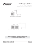
Remote condensing unit
Evaporator unit
Following installation, please forward this manual
to the appropriate operations person.
801 Church Lane • Easton, PA 18040, USA
Toll free (800) 523-9361 • (610) 252-7301
Fax (610) 250-0696 • www.follettice.com
00108647R03
Table of contents
Welcome to Follett Corporation
Specifications
Installation
System layout
Condenser unit installation
Evaporator unit installation
Installing to ice storage and transport bin, top mount
Installing to VU155 or VU300 series dispenser
Refrigeration line installation
System startup
Operation
Cleaning
Weekly exterior evaporator unit care
Recommended semi-annual evaporator unit cleaning
Service
Condenser unit operation
Evaporator unit operation
Technical specifications
Refrigeration system diagram
Evaporator unit wiring diagram
Condensing unit wiring diagram
Water system diagram
Harvest system diagram
Refrigerant charges
Evaporator unit electrical control system operation
Service procedures
Evaporator disassembly
Evaporator reassembly
Gearmotor replacement
Troubleshooting
Replacement parts
3
3
5
5
5
6
6
7
9
9
10
10
10
10
12
12
12
13
13
14
14
15
15
16
17
24
24
24
24
25
28
Follett Corporation
Equipment Return Policy
Follett equipment may be returned for credit under the following conditions:
1. The equipment is new and unused.
2. A return authorization number has been issued by customer service within 30 days after shipment.
3. Follett receives the equipment at the factory in Easton, PA within 30 days after the issuance of the return authorization number.
4. The equipment must be returned in Follett packaging. If the packaging has been damaged or discarded, Follett will forward, at the customer’s expense,
new packaging.
Note:
Return freight charges are the responsibility of the customer. If equipment is returned and is damaged because of improper packaging, Follett
Corporation will not be held responsible.
Credit will be issued when:
The equipment has been inspected by Follett and deemed suitable to be returned to stock.
Note:
A 15% restocking charge will be deducted from the credit. If the cost to return the product to stock exceeds 15%, the actual cost will be deducted.
2
Welcome to Follett
Follett icemakers enjoy a well-deserved reputation for excellent performance, long-term reliability and outstanding
after-the-sale support. To ensure that this icemaker delivers that same degree of service, we ask that you take
a moment to review this manual before beginning the installation. Should you have any questions or require
technical help at any point, please call our technical service group, (800) 523-9361 or (610) 252-7301.
Before you begin
After uncrating and removing all packing material, inspect the equipment for concealed shipping damage. If
damage is found, notify the shipper immediately and contact Follett Corporation so that we can help in the filing of
a claim, if necessary.
!
Important cautions
Ice is slippery. Maintain counters and floors around dispenser in a clean and ice-free condition.
Ice is food. Follow recommended cleaning instructions to maintain cleanliness of delivered ice.
Should local codes require a hard-wired connection and/or shielded wiring, eliminate the cord(s)
and plug(s) and follow the appropriate field wiring diagram on the following page.
Always disconnect power before cleaning dispenser.
Failure to remove all sanitizing solution may result in health hazard.
MC825RVR
Icemaker configuration
R = Satellite-fill
T = Top mount
Application
B = Bin
H = Harmony
V = Vision
Condenser type
R = air-cooled, remote condensing unir
N = air-cooled, no condensing unit (for connection to parallel rack system)
Icemaker capacity and refrigerant
825 = 611 lbs (277kg)/day, R404A
Icemaker model series
MC = Maestro Chewblet
Specifications
Electrical
Refrigeration
Separate circuit and equipment ground required.
Evaporator unit
Liquid line – 3/8"
Suction line – 5/8"
Standard electrical – 120V, 60Hz, 1 phase. Max. fuse – 15 amps
Note:
Condenser unit
Standard electrical – 220V, 60Hz, 1 phase. Max. fuse – 30 amps
Minimum circuit ampacity – 17.6 amps
A rack system requires a reserve
capacity of 8000 BTU/hr at
2°F (-17°C) evaporator temperature.
Weight
Evaporator plumbing
Evaporator unit
Water – 3/8" push-in water inlet
Drain – 3/4" MPT
130 lbs (59kg)
Note:
Condenser unit
Drains should be hard-piped and insulated. Maintain at
least 1/4" per foot (1cm per 31cm run) slope on drain line run.
3
265 lbs (102kg)
Evaporator connections
Ice transport tube outlet
(remote only)
Low pressure refrigerant line
(suction line)
Ice transport tube outlet
(remote only
Ice tranport tube outlet
(remote only)
Low pressure
refrigerant line
(suction line)
High pressure
refrigerant line
(liquid line)
High pressure
refrigerant line
(liquid line)
Bin thermostat cord
(remote only)
Power cord
Water line (3/8" OD tubing)
Drain (3/4" MPT)
Power cord
Water line (3/8" OD tubing)
Drain (3/4" MPT)
Condenser connections
High pressure line
(liquid line)
Power connection
Low pressure line
(suction line)
System details
Evaporator Unit
Top mount
evaporator unit
Remote mount
evaporator unit
Evaporator unit
plug configuration
Front view
Side view
Side view
NEMA 5-15
24.25"
(616mm)
18.00"
(458mm)
Service
loop
14.00"
(356mm)
Service
loop
17.00"
(432mm)
Condenser unit
Condenser unit
Rear view
Top view
WIDTH MAX
(W)
22.63"
(575mm)
HEIGHT MAX
(H)
LENGTH MAX
(L)
25.5"
(648mm)
4"
(102mm)
1.9"
(49mm)
30.75"
(781mm)
4
.5" (13mm)
MTG HOLES
Installation
Icemaker performance is very sensitive to the quality of installation. To ensure proper performance, ease of
service and warranty coverage, it is critical that you follow the requirements detailed in this manual. If you cannot
meet these requirements or have questions, call our technical service group immediately at (800) 523-9361 or
(610) 252-7301.
System layout
Condenser unit
Evaporator
8" (204mm)
12" (305mm)
60"
(1524mm)
24"
(610mm)
Discharge air
Air flow
6"
(153mm)
8" (204mm)
6"
(153mm)
Clearances
Installation Specifications
Outdoor ambient temperature range: – 20°F – 130°F
(– 29°C – 54.4°C).
Refrigeration line
elevation specifications
Indoor ambient temperature range: 50°F – 90°F
(10°C – 32°C).
Condenser unit
Installations with condenser unit above indoor unit
require a suction line S-trap at the bottom of the rise.
Installation with condenser unit elevations above 20 ft (6.1m)
require an additional S-trap at the midpoint of the rise.
additional
S - trap
install
required
Maximum line
height
35 ft
(10.7m)
20 ft+
(6.1m)
Maximum line rise must not exceed 35 ft (10.7m).
Maximum line set length must not exceed 100 feet (30.5m).
Max line drop must not exceed 15 ft (4.6m).
Note:
Condenser unit
The service loop is not included when calculating the
length, rise or drop of the tubing run.
S - trap install
required
3 ft+
(.9m)
Water pressure 10 psi – 70 psi.
Water temperature 50°F – 90°F (10°C – 32°C).
Evaporator unit level
Install condenser unit
Mount condenser unit
1. Level unit.
2. Securely attach base of unit using holes found in
base plate.
Condenser unit
Maximum line
drop
-15 ft
(-4.6m)
Electrical connection
Refer to wiring schematic located in condenser unit
electrical box.
Note:
Electric disconnects required within 10 ft (3m)
for all hard-wired connections.
Note:
Install in accordance with NEC and local
electrical codes.
5
Install evaporator unit
Fig. 1
Installation overview
The evaporator is designed to be installed in the
following applications:
1
1. Ice storage and transport bins, top-mount (Fig. 1.1).
2. VU155 or VU300 series ice and beverage dispensers
(Fig. 1.2).
Installation checklist
The following are used for all installation applications:
❒
❒
❒
❒
❒
❒
❒
2
Locate and level unit
Routing and mounting ice transport tubes
Routing and mounting bin thermostat
Plumbing for water
Plumbing for drain
Routing and connecting refrigerant lines
Start up and testing
Fig. 2
Installing to Ice storage and transport bins, top-mount
Mount evaporator unit
1. Verify bin top is level.
Note:
Do NOT weld or permanently attach evaporator unit.
Removal may be necessary for service.
2. Position icemaker on bin.
a) If new storage bin and icemaker, position icemaker with
connections facing rear of bin.
b) If using existing bin, place supplied gasket 2.5" (64mm)
from front of bin. Position icemaker with utility connections
facing rear of bin.
Routing and mounting ice transport tubes
Ice
transport
tubes
ICE TRANSPORT TUBE
1. Remove icemaker top panel and louvered side panel.
2. Remove transport tubes. Route tubes from inside bin, through
gasket and connect to evaporator port (Fig 2).
Fig. 3
3. Tighten hose clamp to secure tubes to ports.
Routing and mounting bin thermostat
1. Insert thermostat through clamps on transport tube as shown
(Fig. 3).
Plumb for water and drain
1. Connect drain to 3/4" MPT fitting in rear of unit.
2. Connect potable water supply (plastic or copper tubing) to
3/8" push-in connector in rear of unit.
Bin
thermostat capillary tube
Ice
transport
tubes
Bin top
6
Installing to VU155 or VU300 series ice and beverage dispensers
Fig. 4
Correct installation
Mount evaporator unit
Note:
Locate unit within 20 ft (6.1m) of dispenser.
1. Level unit.
2. Securely attach base of unit using holes found in base plate.
Note:
Do NOT weld or permanently attach evaporator unit.
Removal may be necessary for service.
3. Remove front panel of evaporator unit.
Routing and mounting ice transport tubes (Fig. 4).
Incorrect ice transport tube installation can result in wet ice
and dispensing problems. Follow guidelines below to
ensure correct installation. Call factory for assistance if you
are unable to meet these requirements.
Note:
If connecting an MC825 evaporator unit to a manually filled
VU155 or VU300 series dispenser consult dispenser
manual for proper transport tube mounting in dispenser
manual or contact Follett technical service.
Incorrect installation
No dips,
No joints,
No bends of
less than
6" (153mm)
1. Push one end of the supplied ice transport tube(s) through
hole(s) provided in side of dispenser.
2. Route tube into ice tube bracket inside dispenser and engage
bracket tabs in holes located in end of ice transport tube(s)
(Fig. 5).
Fig. 5 – Ice tube retainer bracket
1" (25mm)
ice tube
retaining
bracket
ice tube
ice tube
7
Fig. 6 – Bin thermostat capillary tube mounting
Front view – VU155
Front view – VU300
ice tube
retaining
bracket
thermostat
ice tube
thermostat
tabs in ice tube
retainer bracket
engage holes in ice
tube and hold tube
in place
ice tube
retaining
bracket
ice tube
thermostat
3. Verify bin thermostat capillary tube is mounted correctly (Fig. 6).
4. Run tube from dispenser to icemaker, and cut to length.
Note:
Tubes may NOT have dips, may NOT have bends of less than 6" (153mm) radius,
and may NOT have splices/joints.
5. Cut insulation off tube where tube enters grommet.
6. Slide end of tube without insulation through grommet and run to evaporator port.
7. Install a section of insulation on tube from grommet to evaporator port.
8. Slip supplied hose clamp over free end of tube.
9. Pull insulation back from free end of tube.
10. Push tube on evaporator port.
11. Position clamp behind lip on evaporator port and tighten clamp.
12. Connect bin thermostat twist-lock cord to dispenser plug.
Install refrigeration line
Note:
The installer of the refrigeration line set must be USA Government-Environmental Protection Agency
(EPA) certified in proper refrigerant handling and servicing procedures.
A qualified person must perform all roof or wall penetration.
Do not form unwanted traps in refrigeration lines. A service loop is not considered an oil trap.
Never coil excess refrigeration tubing.
The compressor oil rapidly absorbs moisture. Minimize the exposure of the refrigeration system by
not releasing the condenser unit or evaporator unit holding charge until all line connections are
finished and the system is ready for evacuation.
To prevent oxidation of the copper, purge line set and condenser unit with dry nitrogen while brazing.
For lines longer than fifty feet, add one additional pound of R404A refrigerant for every 25 feet of line run
up to 100 feet (see refrigeration charge table). Consult factory for line runs beyond 100 feet.
It is recommended that both liquid and suction lines are run and insulated together for the first 15
feet from the condensing unit. This protects the system from sub-cooling loss and/or liquid slugging
the compressor.
8
1. Make line set run from the condenser unit to the evaporator unit in accordance with all specifications
found in the Installation specifications section.
2. Braze all connections. Do not overheat shut off valves on condenser unit or evaporator unit.
3. Pressurize line sets and check for leaks.
4. Bleed off line set.
5. Open the liquid line valve and suction line valves on evaporator unit.
6. Energize liquid line solenoid valve. Valve can be energized by supplying electrical power to evaporator
unit and filling float reservoir and evaporators with water. Do NOT connect power to condensing unit until
evacuation is complete and vacuum has been broken with R404A refrigerant.
7. Open the liquid line valve, then the suction line valve on the condenser unit.
8. Evacuate refrigeration system to 500 microns or less. Verify system holds vacuum for 30 minutes
with the pump off and the system isolated.
9. Add 8 lbs R404A to refrigeration system for up to 50 ft (15.2m) line length. See chart below for line length
longer than 50 ft (15.2m)
R404A icemaker charge specifications
Model
825
Line Run
Charge
0 – 50 ft (0 – 15.2m)
8 lbs (3.6kg)
50 – 75 ft (15.2 – 22.9m)
9 lbs (4.1kg)
75 – 100 ft (22.9 – 30.5m)
10 lbs (4.5kg)
100 ft+ (30.5m+)
Consult factory
10. Insulate entire suction line including shut off valves to prevent condensation.
11. Adjust the condenser unit low pressure control set points to a cut-in of 30psi and a cut-out of 10psi.
Pressure adjustment
1. Turn cut-in adjusting screw (Fig. 7.1)
clockwise until indicator points to 30psig on
cut-in scale. Cut-in MUST be adjusted first.
Fig. 7
2
1
2. Turn cut-out adjusting screw (Fig. 7.2)
counter clockwise until indicator points to
10psig on cut-out scale.
3. Do NOT adjust high pressure cut-out
adjusting screw (Fig. 7.3). Control is preset
to cut-out at 450psig.
cut out
scale
3
cut in
scale
Startup and test
1. Plug evaporator unit in.
2. Turn dispenser power ON if applicable.
3. Turn condenser unit power ON.
4. Check to make sure unit makes ice.
5. Put a piece of ice on bin thermostat and verify that the evaporator unit shuts OFF.
6. Restart icemaker.
9
Operation
Preventive maintenance
Periodic cleaning of Follett’s icemaker system is required to ensure peak performance and delivery of clean,
sanitary ice. The recommended cleaning procedures that follow should be performed at least as frequently as
recommended and more often if environmental conditions dictate.
Cleaning of the icemaker system, in most cases, should be performed by your facility’s maintenance staff or a
Follett authorized service agent. Regardless of who performs the cleaning, it is the operator’s responsibility to
see that this cleaning is performed according to the schedule below. Service problems resulting from lack of
preventive maintenance will not be covered under the Follett warranty.
Weekly exterior evaporator unit care
The exterior may be cleaned with a stainless cleaner such as 3M Stainless Steel Cleaner & Polish or equivalent.
Recommended monthly cleaning of condenser (air-cooled icemaker only)
Solution A – Sanitizing solution:
Prepare 1 gallon (3.8L) of 200ppm 5.25% Sodium Hypochlorite solution
(mix 1 oz household bleach to 2 gallons water) or equivalent. Solution
temperature must be at least 120 F (48.9°C).
Fig. 8
2
Solution B – Ice machine solution:
1
Following manufacturer's instructions, prepare one 7oz packet of Follett
SafeCLEAN™ Ice Machine Cleaner or equivalent. Solution temperature
must be at least 120 F (48.9°C).
1. Remove evaporator unit panels required to gain access to water
reservoir components (Fig. 7) and electrical control box (Fig. 8).
3
2. Turn compressor switch OFF (Fig. 8.3).
Fig. 9
3. Dispense all ice from dispenser.
4. Shut OFF water valve.
5. Drain water from reservoir through float/evaporator drain line
(Fig. 7.1). Reinsert hose into hose clip (Fig. 7.3).
6. Remove water reservoir lid and fill reservoir (Fig. 7.2) with Solution B.
7. Restart icemaker and allow gearmotor to run with the compressor off
for 15 minutes.
8. While waiting 15 minutes, follow step 8a through 8c.
a) Remove ice compression nozzles (Fig. 9.1). Soak in Solution B.
b) Descale drain pans (Fig. 9.2) by grasping firmly an gently bending
up and down. Vacuum residue out.
c) Inspect all drain lines. Clean as necessary with Solution B.
9. Turn bin signal switch (Fig. 8.1) on electrical box of icemaker OFF.
10. Drain Solution B through float/evaporator drain line (Fig. 7.1). Rinse
evaporator by filling reservoir (Fig. 7.2) with potable water and draining
evaporator through float/evaporator drain line (Fig. 7.1) three times.
Reinsert hose to hose clip and plug into end of drain line (Fig. 7.1).
11. Connect ice transport tubes (Fig. 9.3) directly to evaporator outlet
ports (without ice compression nozzle) (Fig. 9.4).
Note: If bin will not be cleaned at this time place a large pan in the
storage area to catch ice or connect a separate ice transport tube to
evaporators and divert ice into a separate container.
10
1
2
3
Fig. 10
12. Fill reservoir (Fig. 7.2) with Solution A.
13. Turn bin signal switch (Fig. 8.1) on electrical box of icemaker ON (to
allow gearmotor to run).
14. Wait 10 minutes. Turn compressor switch ON (Fig. 8.3).
1
15. Keep reservoir (Fig. 7.2) full of Solution A while making ice for 20
minutes.
16. Turn compressor switch OFF (Fig. 8.3).
17. Rinse ice compression nozzles (Fig. 9.1) with water and reinstall.
18. Drain any remaining sanitizing solution from reservoir through float/
evaporator drain line (Fig. 7.1).
19. Fill reservoir (Fig. 7.2) with 120°F (49°C) water. Empty water through
float/evaporator drain line (Fig. 7.1). Repeat 3 times.
3
4
20. Turn ON water to icemaker.
21. Turn compressor switch ON (Fig. 9.3).
22. Replace reservoir cover and any panels removed to clean icemaker.
23. Make ice for 15 minutes to flush any remaining solution from system
(remote icemakers with long transport tubes may take longer to flush
out). Discard this and all ice made during sanitizing.
24. Replace float reservoir lid and evaporator unit panels.
2
11
Service
Condenser unit operation
The condensing unit is weatherproof and equipped to operate in ambient temperatures from – 20°F – 130°F
(– 29°C – 54.4°C). A dual pressure control provides compressor protection from excessive head pressures,
pumps the refrigeration system down and shuts the condensing unit off when the solenoid valve on the
evaporator unit is closed.
Low ambient operation: Reliable operation at low ambient temperature is achieved with a pumpdown cycle, a
crankcase heater and a head pressure control valve. As the ambient temperature falls and the head pressure
decreases the valve maintains a minimum head pressure of 215 psi by bypassing discharge gas around the
condenser to the receiver to increase the pressure at the condenser outlet. This backs liquid refrigerant up in the
condenser to reduce the area available for condensing which increases the head pressure to maintain the 215
psi set point. A check valve is installed in the liquid line between the receiver and the condenser to prevent liquid
migration from the receiver to the condenser during the off cycle. The crankcase heater works in conjunction with
a continuous pumpdown cycle to prevent accumulation of liquid refrigerant in the compressor oil during the off
c
This prevents compressor damage due to a flooded compressor start. The low pressure control will start the
condensing unit anytime the low side pressure rises above the 30 psi set point and pump the refrigerant out until
the pressure falls to 10 psi. The crankcase heater, which is energized whenever the condensing unit has power,
keeps the compressor oil warmer than the coldest location in the system. This minimizes off cycle refrigerant
migration. If power to the condensing unit is interrupted after the system is charged the compressor should not be
started unless the crankcase heater has been energized for at least four hours immediately prior to compressor
startup. However the compressor can safely be started during the refrigeration system charging process (without
the warm-up period) once sufficient refrigerant is in the system to maintain a positive pressure on the suction side
of the compressor.
Evaporator unit operation
Follett’s icemaker consists of four distinct functional systems:
1.
2.
3.
4.
Refrigeration system
Electrical control system
Water system
Harvesting system
These four systems work together to accomplish the production and harvesting of ice. A problem in any one
of these systems will result in improper operation of the entire ice production cycle. When troubleshooting the
icemaker, it is important to analyze the entire system operation to determine which system is not functioning
properly, then pinpoint the component within that system that is malfunctioning. Determine what corrective action
must be taken before making any adjustments or replacing any components.
The icemaking process
The Follett icemaker uses a stainless steel jacketed evaporator and operates on a continuous freezing cycle. Water is
supplied to the evaporator from the water reservoir where the water level is controlled by a float valve. This valve also
shuts off the water supply when the icemaker is not running.
When the icemaker is running, a layer of ice forms on the interior surface of the evaporator. This ice is continuously
removed by a slowly rotating (12 RPM) auger. The auger carries the ice upward into the cavity formed by the top
bearing housing and the compression loop, where it is compressed to remove excess water. When the ice reaches
the desired hardness it rotates within the cavity and is forced through a discharge port and compression nozzle and
into the ice transport tube. The discharge tube and compression nozzle are slightly restricted to further compress the
ice and produce the desired hardness. As the formation of ice continues, ice in the transport tube is pushed through
the tube to the storage compartment in the ice dispenser or ice storage bin.
A solid state control board located in the electrical box of the icemaker controls the normal operation of the icemaker
and monitors gearmotor torque. This control board will shut down the icemaker should an over-torque condition
occur. It is very important that you familiarize yourself with the operational sequences detailed in this manual before
attempting to service the icemaker.
12
Technical specifications
Refrigeration system diagram
High side
service valve
with service port
Condenser unit
Low side
service valve
with service port
Compressor
Condenser
Head control valve, 215 PSI
Check valve
Receiver
14 pounds
Low side
service port
Filter -drier
with sight glass
Evaporator unit
Low side
service valve
with service port
Low side
refrigeration
line run
High side
refrigeration
line run
Thermostatic
expansion
valve
High side
service port
Sight glass
Filter-drier
Solenoid valve
13
High side
service valve
with service port
Evaporator unit wiring diagram
115 VAC
60 HZ
ELECTRICAL BOX
x
GREEN
BLACK
WHITE
POWER
SWITCH
BLACK
L1
BLACK
L2
WTR PROBE
PWR
WHITE
1
3
4
6
C
RESET
20M
COMP
60M
START
RELAY
3
2
4
FAN
7
WATER
SENSOR
DR
WHITE
9
COMPRESSOR
SWITCH
2ND
WTR
A
B-T
B
B-E
DRV
COMP
HIGH VOLTAGE BIN
RED
YELLOW
RED
HP SW
PURPLE
WHITE
WHITE
WHITE
BLACK
BLUE
YELLOW
RUN
START
BLACK
BIN LOW V
BLUE
WTR PROBE
L1
PWR
GEAR MOTOR
3
4
6
DR
WHITE
C
RESET
20M
COMP
60M
FAN
3
START
RELAY
4
2
9
7
2ND
WTR
A
B
WHITE
YELLOW
BLUE
Solenoid Valve
Condensing unit wiring diagram
Orange
Dual pressure control
Blue
HP
Black
L1
LP
L2
GND
Fan
Blue
Crankcase heater
Black
Black
Blue
Black
Black
Black
S Cap
R Cap
C
Black
4
1
5
6
HP SW
COMP
HIGH VOLTAGE BIN
BLACK
YELLOW
RED
RUN
BLACK
BLUE
GEAR MOTOR
BIN
SIGNAL
SWITCH
B-T
B-E
DRV
BIN LOW V
START
WHITE
BLACK
1
BLACK
L2
WHITE
Yellow
S
2
Black
Red
14
R
BIN
SIGNAL
CORD
Water system diagram
Evaporator
service drain
Reservoir
overflow
Water
level
Water
level
Water in
Evaporator
drains
Strainer
Shut-off
valve
Harvest system diagram
Evaporator
port
Ice tranport
tube
Compression
nozzle
Auger
Water
inlet
15
Refrigeration charges
R404A icemaker charge specifications
Model
825
Line Run
Charge
0 – 50 ft (0 – 15.2m)
8 lbs (3.6kg)
50 – 75 ft (15.2 – 22.9m)
9 lbs (4.1kg)
75 – 100 ft (22.9 – 30.5m)
10 lbs (4.5kg)
100 ft+ (30.5m+)
Consult factory
Refrigeration replacement requirements
Non-contaminated refrigerant removed from any Follett refrigeration system can be recycled and returned to
the same system after completing repairs. Recycled refrigerant must be stored in a clean, approved storage
container. If additional refrigerant is required, virgin or reclaimed refrigerant that meets ARI standard 700-88 must
be used.
In the event of system contamination (for example, a compressor burn out, refrigerant leak, presence of noncondensibles or moisture), the system must be repaired, evacuated and recharged using virgin or reclaimed
refrigerant that meets ARI standard 700-88.
Follett Corporation does not approve of recovered refrigerants. Improper refrigeration servicing procedures will
void the factory warranty.
16
Evaporator unit electrical control system operation
The wiring diagrams which follow illustrate the circuitry of Follett icemakers used with ice dispensers. Both normal
operation of the icemaker (Stages 1 – 6) and non-normal diagnostic sequences showing torque out (Stages 7 – 9)
for use in troubleshooting icemaker problems are shown.
Normal operation – Stage 1 – Start-up
Power is supplied to L1 on the control boards. The ice level control in the storage bin is closed completing the
circuit between the terminals of the low voltage bin signal connection*. The control boards will now go through the
start-up sequence. Less than 30 seconds will elapse as the water sensor located in the float reservoir checks for
water in the reservoir. The Bin Empty LED (B-E) will be on.
*The high voltage bin signal connection is used on all Follett ice dispenser applications. The high voltage terminals
respond to applied voltage of 24 to 240 volts from the dispenser.
115 VAC
60 HZ
ELECTRICAL BOX
x
GREEN
BLACK
WHITE
POWER
SWITCH
BLACK
L1
BLACK
L2
WTR PROBE
PWR
WHITE
3
4
6
RESET
COMP
START
RELAY
3
2
4
FAN
7
9
A
B
DRV
HP SW
COMP
COMPRESSOR
SWITCH
HIGH VOLTAGE BIN
RED
YELLOW
BLUE
PURPLE
WHITE
WHITE
WHITE
BLACK
YELLOW
BLUE
RUN
START
BLACK
BIN LOW V
WATER
SENSOR
RED
1
DR
C
20M
60M
2ND
WTR
B-T
B-E
WHITE
WTR PROBE
L1
PWR
GEAR MOTOR
3
4
6
7
9
A
B
WHITE
RESET
COMP
START
RELAY
3
2
4
FAN
DRV
RED
WHITE
YELLOW
BLUE
GEAR MOTOR
Solenoid Valve
HP SW
COMP
HIGH VOLTAGE BIN
BIN
SIGNAL
SWITCH
BLACK
YELLOW
BLUE
RUN
START
BLACK
BIN LOW V
DR
C
20M
60M
2ND
WTR
B-T
B-E
WHITE
BLACK
1
BLACK
L2
WHITE
17
BIN
SIGNAL
CORD
Normal operation – Stage 2 – Gearmotor start
The water sensor verifies water in the float. The Water OK LEDs (WTR) comes on. At the same time, the
gearmotors come on, lighting the Drive LEDs (DR). The gearmotor start windings are energized through a current
relay. The B-E and WTR LED remain on.
115 VAC
60 HZ
ELECTRICAL BOX
x
GREEN
BLACK
WHITE
POWER
SWITCH
BLACK
L1
BLACK
L2
WTR PROBE
PWR
WHITE
3
4
6
RESET
COMP
START
RELAY
3
2
4
FAN
7
9
A
B
DRV
HP SW
COMP
COMPRESSOR
SWITCH
HIGH VOLTAGE BIN
RED
YELLOW
BLUE
PURPLE
WHITE
WHITE
WHITE
BLACK
YELLOW
BLUE
RUN
START
BLACK
BIN LOW V
WATER
SENSOR
RED
1
DR
C
20M
60M
2ND
WTR
B-T
B-E
WHITE
WTR PROBE
L1
PWR
GEAR MOTOR
3
4
6
7
9
A
B
WHITE
RESET
COMP
START
RELAY
3
2
4
FAN
DRV
RED
WHITE
YELLOW
BLUE
GEAR MOTOR
Solenoid Valve
HP SW
COMP
HIGH VOLTAGE BIN
BIN
SIGNAL
SWITCH
BLACK
YELLOW
BLUE
RUN
START
BLACK
BIN LOW V
DR
C
20M
60M
2ND
WTR
B-T
B-E
WHITE
BLACK
1
BLACK
L2
WHITE
18
BIN
SIGNAL
CORD
Normal operation – Stage 3 – Refrigeration start
Seconds later the C LEDs come on and the coils of both of the relays are energized, closing their normally
open contacts. This completes the circuit to the coil of the liquid line solenoid valve. The valve opens increasing
the pressure in the suction line. The low-pressure control then starts the condensing unit. As the gearmotors
reach normal speed the current relays re-open, dropping out their start windings. The icemaker is now in normal
icemaking mode.
115 VAC
60 HZ
ELECTRICAL BOX
x
GREEN
BLACK
WHITE
POWER
SWITCH
BLACK
L1
BLACK
L2
WTR PROBE
PWR
WHITE
3
4
6
RESET
COMP
START
RELAY
3
2
4
FAN
7
9
A
B
DRV
HP SW
COMP
COMPRESSOR
SWITCH
HIGH VOLTAGE BIN
RED
YELLOW
BLUE
PURPLE
WHITE
WHITE
WHITE
BLACK
YELLOW
BLUE
RUN
START
BLACK
BIN LOW V
WATER
SENSOR
RED
1
DR
C
20M
60M
2ND
WTR
B-T
B-E
WHITE
WTR PROBE
L1
PWR
GEAR MOTOR
1
3
4
6
7
9
A
B
WHITE
RESET
COMP
START
RELAY
3
2
4
FAN
DRV
RED
WHITE
YELLOW
BLUE
GEAR MOTOR
Solenoid Valve
HP SW
COMP
HIGH VOLTAGE BIN
BIN
SIGNAL
SWITCH
BLACK
YELLOW
BLUE
RUN
START
BLACK
BIN LOW V
DR
C
20M
60M
2ND
WTR
B-T
B-E
WHITE
BLACK
WHITE
BLACK
L2
19
BIN
SIGNAL
CORD
Normal operation – Stage 4 – Ice bin full
The ice level control opens, the B-E LED goes out. After a 10 second delay the LEDs (C), go off de-energizing the
relays which closes the liquid line solenoid valve. The refrigeration system will pump down and turn off by the low
pressure control. (Should the ice level control not remain open for 10 seconds, the icemaker will continue to run.)
The BT LEDs come on. The gearmotors continue to run for 60 seconds. The purpose of this function is to drive
the remaining ice out of the evaporator and to boil off any refrigerant remaining in the evaporator.
115 VAC
60 HZ
ELECTRICAL BOX
x
GREEN
BLACK
WHITE
POWER
SWITCH
BLACK
L1
BLACK
L2
WTR PROBE
PWR
WHITE
3
4
6
RESET
COMP
START
RELAY
3
2
4
FAN
7
9
A
B
DRV
HP SW
COMP
COMPRESSOR
SWITCH
HIGH VOLTAGE BIN
RED
YELLOW
BLUE
PURPLE
WHITE
WHITE
WHITE
BLACK
YELLOW
BLUE
RUN
START
BLACK
BIN LOW V
WATER
SENSOR
RED
1
DR
C
20M
60M
2ND
WTR
B-T
B-E
WHITE
WTR PROBE
L1
PWR
GEAR MOTOR
3
4
6
7
9
A
B
WHITE
RESET
COMP
START
RELAY
3
2
4
FAN
DRV
RED
WHITE
YELLOW
BLUE
GEAR MOTOR
Solenoid Valve
HP SW
COMP
HIGH VOLTAGE BIN
BIN
SIGNAL
SWITCH
BLACK
YELLOW
BLUE
RUN
START
BLACK
BIN LOW V
DR
C
20M
60M
2ND
WTR
B-T
B-E
WHITE
BLACK
1
BLACK
L2
WHITE
20
BIN
SIGNAL
CORD
Normal operation – Stage 5 – Off cycle time delay
The B-T LEDs will remain on for 20 minutes. The icemaker will not start while the B-T LEDs are on. To restart the
icemaker for troubleshooting purposes, depress both reset buttons to clear the control boards.
115 VAC
60 HZ
ELECTRICAL BOX
x
GREEN
BLACK
WHITE
POWER
SWITCH
BLACK
L1
BLACK
L2
WTR PROBE
PWR
WHITE
3
4
6
RESET
COMP
START
RELAY
3
2
4
FAN
7
9
A
B
DRV
HP SW
COMP
COMPRESSOR
SWITCH
HIGH VOLTAGE BIN
RED
YELLOW
BLUE
PURPLE
WHITE
WHITE
WHITE
BLACK
YELLOW
BLUE
RUN
START
BLACK
BIN LOW V
WATER
SENSOR
RED
1
DR
C
20M
60M
2ND
WTR
B-T
B-E
WHITE
WTR PROBE
L1
PWR
GEAR MOTOR
3
4
6
7
9
A
B
WHITE
RESET
COMP
START
RELAY
3
2
4
FAN
DRV
RED
WHITE
YELLOW
BLUE
GEAR MOTOR
Solenoid Valve
HP SW
COMP
HIGH VOLTAGE BIN
BIN
SIGNAL
SWITCH
BLACK
YELLOW
BLUE
RUN
START
BLACK
BIN LOW V
DR
C
20M
60M
2ND
WTR
B-T
B-E
WHITE
BLACK
1
BLACK
L2
WHITE
21
BIN
SIGNAL
CORD
Normal operation – Stage 6 – Off cycle
When the dwell time of 20 minutes has expired, the B-T LEDs go off. The icemaker will go through the normal
start-up sequence when the bin level control signals for ice. The WTR LED will remain on as long as the water
sensor in the float reservoir senses water.
115 VAC
60 HZ
ELECTRICAL BOX
x
GREEN
BLACK
WHITE
POWER
SWITCH
BLACK
L1
BLACK
L2
WTR PROBE
PWR
WHITE
3
4
6
RESET
COMP
START
RELAY
3
2
4
FAN
7
9
A
B
DRV
HP SW
COMP
COMPRESSOR
SWITCH
HIGH VOLTAGE BIN
RED
YELLOW
BLUE
PURPLE
WHITE
WHITE
WHITE
BLACK
YELLOW
BLUE
RUN
START
BLACK
BIN LOW V
WATER
SENSOR
RED
1
DR
C
20M
60M
2ND
WTR
B-T
B-E
WHITE
WTR PROBE
L1
PWR
GEAR MOTOR
3
4
6
7
9
A
B
WHITE
RESET
COMP
START
RELAY
3
2
4
FAN
DRV
RED
WHITE
YELLOW
BLUE
GEAR MOTOR
Solenoid Valve
HP SW
COMP
HIGH VOLTAGE BIN
BIN
SIGNAL
SWITCH
BLACK
YELLOW
BLUE
RUN
START
BLACK
BIN LOW V
DR
C
20M
60M
2ND
WTR
B-T
B-E
WHITE
BLACK
1
BLACK
L2
WHITE
22
BIN
SIGNAL
CORD
Diagnostic sequence – motor over-current condition
If either of the circuit boards senses a current over 3 amps, five things happen:
1. The DR LED goes out, the DRV terminal is de-energized and the gearmotor shuts down.
2. The C LED goes out, the FAN terminal is de-energized, cutting power to the coil of the relay.
3. The relay contacts open, cutting power to the coil of the solenoid valve and the condensing unit
pumps down.
4. The condensing unit shuts off on the low pressure control.
5. The 20M LED is turned on.
After 20 minutes the 20M light is turned OFF and the machine goes through the normal start-up described above.
If the restart is successful, the 60M light is turned ON and remains ON for 60 minutes. This alerts the user to a
problem in the drive system. If the icemaker runs without an overcurrent condition during the 60 minute period the
60M LED will go out and the icemaker will continue normal operation. If the restart is unsuccessful, or if the board
detects another 3 amp current during the 60 minute period, the 2ND light is turned ON and the machine shuts
down and can only be started by pressing the reset button.
Diagnostic sequence – no water
If the water level in the float reservoir drops too low, three things happen:
1. The WTR light is turned OFF.
2. The ice machine shuts down.
3. The BT light turns ON.
If water is restored, the WTR light will flash, the BT light will turn OFF after 20 minutes, and the machine goes
through the normal start-up described above. The flashing light can be cleared by pressing the reset button.
WTR PROBE
PWR
Status lights
DR
C
DR
If ON, overcurrent has occurred on gearmotor
in past 20 minutes
60M
If ON, overcurrent has occurred on gearmotor, but
successfully restarted in the past 60 minutes
If ON, overcurrent has occured on gearmotor twice
and has shut down
20M
2ND
60M
2ND
WTR
HP SW
COMP
If ON, water sensor detects water
If OFF, water sensor does not detect water
If BLINKING, water sensor detected loss of water
WTR
B-T
If ON, delays restart of IM for 20 minutes
B-T
B-E
If ON, bin stat indicates need for ice
B-E
BIN LOW V
If ON, COMP and FAN terminals are energized
20M
C
RESET
If ON, DRV terminal is energized
HIGH VOLTAGE BIN
See Diagnostic sequence –
no water above
See Diagnostic sequence –
motor over-current condition above
Recognizes
conductivity
through closed
bin thermostat
on storage bin
Compressor Recognizes
switch
24V to 120V
terminals
bin signal from
dispenser
23
Fig. 11
Service procedures
Evaporator disassembly (Fig. 11)
1. Disconnect power to icemaker and shut off water to icemaker.
3. Drain evaporator and float tank.
4. Disconnect plastic tubing from evaporator water inlet, drain pan
stub, compression nozzle tubing and reservoir overflow tubing from
secured clip.
5. Disconnect ice transport tube from compression nozzle.
6. Remove nut and upper vee band coupling from top of evaporator.
7. Lift top bearing assembly straight up with a slight rotating motion and
remove.
8. Remove ice compression loop located at top of auger.
9. Lift auger straight up and out of evaporator.
10. Remove nut and lower vee band coupling from bottom of evaporator.
11. Lift evaporator to clear bottom bearing assembly.
12. Loosen hex head bolt in side of mounting base with 5/16 wrench and
lift lower bearing assembly.
13. Remove condensate shield.
14. Remove 4 Allen head machine screws holding mounting base to
gearbox.
15. If replacing evaporator, remove compression nozzle from evaporator
port.
Evaporator reassembly (Fig. 11)
1. Clean gearmotor boss, output shaft and shaft well.
2. Install drain pan and evaporator mounting base.
3. Fill gearmotor shaft well with food-grade grease.
4. Install condensate shield and seat against gearmotor boss.
5. Install bearing O ring in groove in evaporator mounting base.
6. Lower bottom bearing assembly into evaporator mounting base.
7. While maintaining a slight downward pressure on bottom bearing
assembly, tighten hex head bolt with a 5/16 wrench.
Fig. 12
8. Position evaporator over lower bearing assembly and align grooves
with pins in bearing assembly.
9. Install vee band clamp and nut and tighten to 70 in/lb.
10. Place auger in center of evaporator and rotate to mate with drive pin.
11. Install ice compression loop, orienting loop.
12. Install upper bearing and seal assembly, rotating bearing to slip pin.
into auger slot.
1
13. Install upper vee band clamp and nut and tighten to 70 in/lb.
14. If evaporator was replaced, reinstall compression nozzle on
evaporator.
new
Gearmotor replacement
1. Disassemble evaporator as described above.
2. Disconnect the wire connectors.
3. Remove 4 screws holding gearmotor mounting plate to base of
icemaker and lift gearbox and motor clear of icemaker (Fig. 12.1).
4. Remove machine screws holding mounting plate to motor (Fig. 12.2).
5. Install new motor in reverse order.
24
2
Troubleshooting
Problem: No ice production – evaporator gearmotors not running or only one gearmotor running
Step 1: Check circuit board LEDs on evaporator units.
Indicator
Possible cause
Corrective action
Power LEDs (PWR)
not on.
No power to evaporator unit.
Check that unit is plugged in, circuit
breakers are on.
Bin signal LEDs (BE)
not on.
1. Defective bin thermostat
2. Dispenser bin signal switches turned off.
1. Check ice level control.
2. Return to on position
Water OK LED (WTR) 1. No water in float reservoir
on primary board not 2. Sensor incorrectly installed.
on.
3. Sensor defective.
1. Check water supply to reservoir.
2. Check that both sensor probes are in
the reservoir water.
3. Test sensor by jumping out sensor
connection on board
Bin timer (BT) LEDs
on.
Allow 20 minutes to make sure icemaker
restarts.
Normal shutdown on bin thermostat.
Bin timer (BT) LED
Plugged water filter or water strainer.
on and water OK LED
(WTR) on primary
board flashing.
Verify integrity of water supply.
Drive LEDs (DRV) lit
on both boards.
1. Replace control board.
2. Test/replace gearmotor.
1. No output on drive terminal (DRV)
2. Inoperative gearmotor.
20M, 60M or 2ND LED Icemaker tripping on overload protection.
lit.
Refer to torque-out troubleshooting.
Problem: No ice production – both gearmotors are running
Step 1: Check circuit board LEDs on evaporator units
Evaporators are iced
up, no ice production
1. Float reservoir empty.
2. Air bubble in water supply line, water in
reservoir but not in evaporators.
1. Check for defective water sensor
(WTR LED remains on when float
reservoir is empty).
2. Purge air from line.
No compressor LED
Compressor switch in off position.
(C ) on primary board.
Turn switch to on.
Both compressor
LEDs (C ) are lit,
suction line not cold.
1. Replace defective board
1. No power on fan terminals (FAN) on either
control board.
2. Contacts 4 & 7 on either relay not closing
when fan terminals (FAN) are energized.
3. Defective liquid line solenoid valve/coil.
25
2. Replace defective relay.
3. Replace valve and/or coil.
Step 2: Check outdoor condensing unit
Condensing unit not
running.
1. No power to unit.
2. Low pressure control defective, or
incorrectly set.
3. Refrigerant leak.
Compressor not
running.
1. Defective starting relay.
2. Defective starting capacitor.
3. Defective run capacitor
4. Defective compressor.
1. Check that circuit breakers/disconnect
are on.
2. Check control, adjust or replace.
3. Identify and repair leak.
1. Replace relay.
2. Replace capacitor.
3. Replace capacitor.
4. Replace compressor.
Problem: Low ice production
Step 1: Check evaporator unit
Bubbles in sight
glass and/or incorrect
system pressures.
1. Mineral build-up on evaporator surface.
2. Dirty condenser coil.
3. Restricted airflow to condenser.
4. High outdoor temperature.
5. Defective condenser fan.
6. Low refrigerant charge.
7. Insufficient refrigerant charge for low
ambient operation.
8. Defective head pressure control valve.
9. Inefficient compressor.
10. Faulty expansion valve(s).
1. Clean evaporator with liquid icemaker
cleaner.
2. Clean condenser.
3. Remove obstruction.
4. Verify ice production capacity.
5. Replace condenser fan.
6. Check for leaks; repair, evacuate, and
re-charge refrigeration system.
7. Check system charge.
8. Replace head pressure control valve.
9. Replace compressor.
10. Replace expansion valve.
Problem: Outdoor unit cycles frequently during off cycle
Step 1: Check evaporator unit
Suction pressure rises 1. Leaking liquid line solenoid valve.
during off cycle.
2. Excessive leak back through compressor
valves.
1. Replace solenoid valve.
2. Replace compressor
Problem: Outdoor unit cycles intermittently during run cycle
Step 1: Check condensing unit
Check system
pressures.
1. Low refrigerant charge.
2. Low pressure control defective, or
incorrectly set.
3. Tripping head pressure control.
26
1. Check for leaks; repair, evacuate, and
re-charge refrigeration system.
2. Check control, adjust or replace.
3. Clean condenser, check fan motor
Problem: evaporator unit leaks water
Step 1: Check evaporator unit
Water overflowing
1. Drain lines clogged.
evaporator drain pans. 2. Float level in reservoir set incorrectly or
valve defective.
3. Ice transport tubes not insulated.
1. Clear drain lines.
2. Adjust float or replace reservoir
assembly.
3. Insulate tubes.
Water leaking from
bottom of evaporator
Replace bearing housing O ring.
O ring seal is broken.
Problem: Torque out
20M LED comes on at 1. Gearmotor does not run, draws
startup.
approximately 7 to 8 amps.
2. Gearmotor does not run, draws
approximately 13 to 14 amps.
3. Gearmotor runs briefly, draws
approximately 10 to 11 amps.
1. Clean evaporator with liquid
icemaker cleaner.
2. Eliminate kink and check that tube
2. Kink in ice transport tube.
routing complies with installation
guidelines.
3. Replace ice transport tube.
3. Ice transport tube ruptured internally.
4. Inspect bearings for roughness,
4. Worn evaporator bearings.
binding – replace if necessary.
5. Bin level control remains in closed position. 5. Replace ice level control.
6. Ensure that ice contacts capillary tube
6. Bin thermostat capillary tube incorrectly
before backing up in ice transport
mounted.
tube. Refer to dispenser manual for
proper mounting.
1. Mineral build-up on evaporator surface.
Icemaker makes ice
then 20M LED
comes on.
1. Gearmotor starting relay is defective.
Replace relay.
2. Gearmotor is locked. Replace
gearmotor.
3. Gearmotor starting relay is defective.
Replace relay.
27
Replacement parts
Panels
1
4
8
8
5
2
9
7
3
6
Reference #
Description
1
2
3
4
5
6
7
8
9
Cover, top
Panel, rear
Panel, right side
Panel, left side
Panel, front, remote
Panel, front, top mount
Base, evaporator unit
Grommet, ice
Cover, electrical box
Part #
00110452
00110460
00110478
00110486
00110494
00110502
00110510
501921
00110528
28
Evaporator unit
14
13
16
11
4
12
8, 9
1
5
Reference #
Description
1
2
3
Not shown
4
5
6
7
8
9
10
11
12
13
14
15
Not shown
Not shown
Not shown
Not shown
Not shown
16
Float & reservoir
Strainer, water
Valve, water shut off
Clip, shut off valve
Fitting, water inlet
Fitting, drain
Elbow, water
Filter drier
Expansion valve
Insulation, TXV
Insulation, TXV bulb
Sight glass
Coil, solenoid valve
Ice compression nozzle
Reservoir water line
Service valve
Evaporator water feed line
Y fitting, water feed line
Drain line, evaporator
Elbow, drain line
Tee, drain line
Solenoid valve
4
6
2
15 3 7
Part #
500504
502920
502921
502922
502924
00109728
502925
502724
502726
502830
00106534
00107045
00112847
502220
502079
00107060
501191
00110536
501966
501753
501754
00107052
29
Control box
3
3
3
1
2
1
2
Reference #
Description
1
2
3
Control board
Relay
Switch rocker
Part #
00106690
501369
502209
Miscellaneous
Description
Not shown
Not shown
Not shown
Not shown
Not shown
Not shown
Not shown
Part #
Transport tube, 10 ft (3m), for units with remote I/M
Transport tube, 20 ft (6.1m), for units with remote I/M
Transport tube (sold by the foot)
Transport tube insulation (sold by the foot)
Follett QC4-FL4S water filter system (includes FL4S primary cartridge
and head, coarse pre-filter and head, pressure gauge, flushing valve;
assembled and installed on mounting bracket)
Follett FL4S primary replacement cartridge
Everpure coarse pre-filter cartridge
30
502522
502523
500366
501176
AFSYSTMFL43
AFCARTFL4S
AFPRECART
Evaporator
Reference # Description
1
2
3
4
5
6
7
8
9
10
11
12
13
14
16
17
18
19
20
21
22
23
All above
Not shown
Not shown
Part #
Coupling, vee band, includes nut
Bearing assembly, top
Loop, ice compression, beveled
Auger
Evaporator
(includes insulation jacket, 502740)
O ring, bearing housing
Bearing assembly, bottom
(includes O rings and condensate shield)
O ring, mounting base
Shield, condensate
Screw, Allen 1/4 20 x 1/2 (set of 4)
Mounting base, evap. (includes 501063)
Bolt, mounting base
Gearbox & motor assembly
Compression nozzle, with double drain
Drain pan, evaporator
Clamp, compression nozzle and screw
Tubing, compression nozzle drain(s)
(sold by foot)
Bracket, drain hose
Insulation jacket, evaporator
Relay, start, gearmotor
Drip cover, gearmotor
Mounting base, gearbox
Evaporator & gearmotor assembly
Grease, Chevron SRI-2, 14oz
Oil, gearmotor (pint)
502735
502736
502110
502737
502725
2
1
3
17
4
500496
502738
501063
500744
501080
502733
502227
502730
502220
502727
502226
500680
14
5
18
1
7
19
8
6
10
11
502739
502740
502742
502744
502729
502743
501111
502775
12
22
16
9
21
13
23
31
20
Condensing unit
9
Top View
7
11
6
10
5
1
3
8
8
12
Side View
7
6
3
1
4
5
Reference #
Description
1
Not shown
Not shown
Not shown
2
3
4
5
6
7
8
9
10
Not shown
11
12
Compressor
Starting capacitor
Run capacitor
Starting relay
Crankcase heater
Head pressure control valve
Check valve
Filter drier/sight glass
Receiver
Receiver service valve
Service valve, suction line
Condenser
Condenser fan motor
Condenser fan blade
Condenser fan guard
Shroud
2
Part #
801 Church Lane • Easton, PA 18040, USA
Toll free (800) 523-9361 • (610) 252-7301
Fax (610) 250-0696 • www.follettice.com
00110544
00110569
00110577
00110585
00123042
00110619
00110650
00123059
00110627
00110692
00110643
00110668
00110601
00123067
00123075
00120170
®
U® L
00108647R03
03/05