1
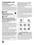
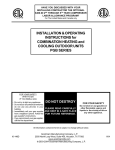
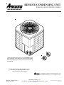
REMOTE CONDENSING UNIT INSTALLATION INSTRUCTIONS R These installation instructions cover the outdoor installation of remote condensing units. See the Product Data Book applicable to your model* for information regarding accessories. C R *NOTE: Please contact your distributor or our website for the applicable product data book referred to in this manual. is a trademark of Maytag Corporation and is used under license to Goodman Company, L.P. All rights reserved. ® Part No. 10652423 Rev. 1 Printed in U.S.A. Goodman Company, L.P. 1810 Wilson Parkway • Fayetteville, Tennessee 37334 www.amana-hac.com 2003-2004 Goodman Company, L.P. March 2004 Table Of Contents Safety Instructions ......................................................................................................................... 3 Recognize Safety Symbols, Words, and Labels ................................................................................................... 3 General Information ....................................................................................................................... 4 Shipping and Handling ........................................................................................................................................... 4 Clearances and Accessibility ................................................................................................................................. 4 Rooftops Installations Only .................................................................................................................................... 4 Application Note ..................................................................................................................................................... 4 Refrigerant Piping .......................................................................................................................... 5 Refrigerant Vapor Line Sizing ................................................................................................................................ 5 Refrigerant Vapor .................................................................................................................................................... 5 and Liquid Lines Routing ....................................................................................................................................... 5 Sweat Connections ................................................................................................................................................. 5 Safe Refrigerant Handling ............................................................................................................. 6 Leak Testing ............................................................................................................................................................ 7 System Evacuation ................................................................................................................................................. 8 Electrical Connections ................................................................................................................... 9 System Startup ............................................................................................................................. 11 Preliminary Charge Adjustment .......................................................................................................................... 11 Final Charge Adjustment ...................................................................................................................................... 11 (Matching Systems-Cooling Operation) .............................................................................................................. 11 Final Charge Adjustment ...................................................................................................................................... 12 (Non-Matching Systems—Cooling Operation) ................................................................................................... 12 Troubleshooting ........................................................................................................................... 13 Qualified Servicer Only ................................................................................................................ 13 2 Safety Instructions Recognize Safety Symbols, Words, and Labels The following symbols and labels are used throughout this manual to indicate immediate or potential safety hazards. It is the owner’s and installer’s responsibility to read and comply with all safety information and instructions accompanying these symbols. Failure to heed safety information increases the risk of personal injury, property damage, and/or product damage. WARNING WARNING - Hazards or unsafe practices which COULD result in severe personal injury or death. CAUTION CAUTION - Hazards or unsafe practices which COULD result in minor or moderate personal injury, product damage, property damage. WARNING To avoid personal injury, shock, or death, ensure the electrical disconnect switch(es) is (are) in the OFF position before installing, modifying, or servicing the unit. Lock out and tag the switch with a suitable warning label. Wiring must conform with NEC or CEC and all local codes. Safety Guidelines 1. Allow only qualified, experienced technicians to install or service this unit. 2. Install the system in accordance with all local codes. If no local codes exist, follow National Codes (NEC in the U.S., CEC in Canada). 3. Open the electrical disconnect switch(es) before electrically connecting the unit. 4. Before operating the unit, be certain it is properly grounded. 5. The unit contains refrigerant gas under pressure. Avoid puncturing or breaking any tubing. 6. Before operating the unit, complete the refrigerant connections. 3 General Information remaining side of the unit must be unrestricted. Ensure that there is at least five feet clearance above the unit. These minimum clearances do not guarantee adequate service access. Sufficient clearances for servicing the unit(s) must be provided. Shipping and Handling Units are securely packed in shipping containers approved by the International Safe Transit Association. Check the carton upon arrival for external damage. If damage is found, file a request in writing for inspection by the carrier agent immediately. The carrier is responsible for making prompt inspection of damage and for a thorough investigation of each claim. The distributor or manufacturer will not accept claims from dealers for transportation damage. If no damage is found, carefully remove all shipping material and properly dispose of it. If installing two or more units at the same location, allow at least 24 inches between the units when using the 6”-12”12” guidelines in Figure 1. The space between two units may be reduced to 12” if the clearances in Figure 1 are increased to 12”-24”-24”. Keep the unit as upright as possible. Laying the unit on its side or top could cause equipment damage. MINIMUM CLEARANCES Clearances and Accessibility 12" 5' DO NOT locate the unit: – – – – Directly under a vent termination for a gas appliance. Within three feet of a clothes drier vent. Where water may rise into the unit. Where the noise would prove to be a nuisance to the customer (i.e. windows, patios, decks, etc.) DO locate the unit: – In accordance with the minimum clearances described in Figure 1. – To minimize the length of refrigerant piping required. – To provide adequate service clearances. – On a level concrete pad (or other sturdy, weather resistant platform). – Isolated from the building structure to avoid transmission of vibrations. 12" 6" SIDE VIEW Figure 1 Rooftops Installations Only Place the unit on a level, weather resistant platform. Be sure the roof will support the weight of the unit and platform. For approximate unit weight, see the Product Data Book applicable to your model*. If in doubt about the adequacy of the roof, it is your responsibility to contact a qualified architect or structural engineer before installing the unit. In general, short runs of refrigerant piping are better than long runs. If practical, locate the unit accordingly. Locate the unit to provide safe access for future maintenance and service. If possible, discuss unit location with the owner before proceeding. Application Note This unit is for outdoor installation only. It cannot be completely enclosed. Refer to Figure 1 for clearances from the sides of the unit to full walls and other objects. For proper performance, the indoor equipment and ductwork must be adequate for moving about 400 CFM of indoor air for every ton of cooling capacity to be installed. If they are not, modify the ductwork or indoor equipment accordingly. Minimum clearances are required to avoid air recirculation and keep the unit operating at peak efficiency. A minimum six inch clearance is required on one side of the unit, and a minimum of twelve on two other sides. The 4 Refrigerant Piping Refrigerant Vapor Line Sizing Sweat Connections IMPORTANT: To avoid overheating the service valve, TXV valve, or filter drier while brazing, wrap the component with a wet rag, or use a thermal heat trap compound as recommended by the compound manufacturer. Use a brazing alloy of 2% minimum silver content. Do not use flux. 1. The ends of the refrigerant lines must be cut square, deburred, cleaned, and be round and free from nicks or dents. Any other condition increases the chance of a refrigerant leak. 2. After brazing, quench the joints with water or a wet cloth. This will also help prevent overheating of the service valve. See the Product Data Book applicable to your model* for required tubing sizes. Using smaller vapor lines may decrease performance up to 10%. These sizes are suitable for line lengths of fifty feet or less. It also assumes that the indoor coil will not be more than forty feet above or below the outdoor unit. Longer runs and greater lifts are not recommended. If a run of more than fifty feet is required, refer to the Remote Cooling Service Manual or contact your distributor for assistance. Check the indoor coil liquid and vapor line diameter. A bushing or coupling may be needed to match with the line sizes used. If mix-matching to a restrictor orifice indoor coil, check the Product Data Book applicable to your model* for the proper orifice size to be used with this outdoor unit. Piston orifices are supplied with the outdoor unit. Refrigerant Vapor and Liquid Lines Routing All of the vapor line must be insulated. The insulation must include a vapor barrier. The liquid line must be outside the vapor line insulation. If part of the liquid line must run through an area that will be hotter than 120°F, then that portion of the liquid line must be insulated. Avoid burying refrigerant lines. If you must bury them, first dig the trench so it gradually slopes toward the compressor (at least 1 inch per 10 feet). Then, insulate the liquid and suction lines separately. Enclose all underground portions of the refrigerant lines in waterproof material (conduit or pipe). If the lines must pass under or through a concrete slab, be sure they are adequately protected. • • Seal the holes where the refrigerant piping enters the building. Be careful not to kink or dent the refrigerant lines. Kinked or dented lines will cause poor performance or compressor damage. NOTE: The service valve connections are oriented at a 45° angle to the unit. Either side of the unit adjacent to the valves can be conveniently located toward the house. *NOTE: Please contact your distributor for the applicable product data book referred to in this manual. 5 Safe Refrigerant Handling While these items will not cover every conceivable situation, they should serve as a useful guide. WARNING To avoid possible injury, explosion or death, practice safe handling of refrigerants. WARNING Refrigerants are heavier than air. They can “push out” the oxygen in your lungs or in any enclosed space. To avoid possible death or difficulty in breathing: • • • • • Never sniff a refrigerant. Never purge refrigerant into an enclosed room or space. In fact, all refrigerants must, BY LAW, be reclaimed. If an indoor leak is suspected, thoroughly ventilate the area before beginning work. Liquid refrigerant can be very cold. To avoid possible frostbite or blindness, avoid contact and wear gloves and goggles. If liquid refrigerant does contact your skin or eyes, get medical help immediately. Always follow EPA regulations. Never burn refrigerant, as poisonous gas will be produced. WARNING To avoid possible explosion: • • • • Never apply flame or steam to a refrigerant cylinder. If you must heat a cylinder for faster charging, partially immerse it in warm water. Never fill a cylinder more than 80% full of liquid refrigerant. Never add anything other than R-22 to an R-22 cylinder. Service equipment used must be listed or certified for R-22. Store cylinders in a cool, dry place. Never use a cylinder as a platform or a roller. WARNING To avoid possible explosion, use only returnable (not disposable) service cylinders when removing refrigerant from a system. • • • Ensure the cylinder is free of damage which could lead to a leak or explosion. Ensure the hydrostatic test date does not exceed 5 years. Ensure the pressure rating meets or exceeds 400 lbs. When in doubt, do not use cylinder. 6 Safe Refrigerant Handling Leak Testing WARNING To avoid the risk of fire or explosion, never use oxygen, high pressure air or flammable gasses for leak testing of a refrigeration system. WARNING To avoid possible explosion, the line from the nitrogen cylinder must include a pressure regulator and a pressure relief valve. The pressure relief valve must be set to open at no more than 150 psig. 1. Be sure both hand valves on the gauge manifold are closed relative to the center port (i.e., turned IN all the way.) Attach this gauge manifold to the service valves on the unit (see Figure 2). Do not open the unit service valves. Do not use refrigerant from the unit for leak testing - it has been precisely measured at the factory for optimum performance. WARNING To avoid possible explosion or equipment damage, do not exceed 150 psig when pressure testing. After you reach 150 psig, close the valve on the nitrogen cylinder. Disconnect it from the gauge manifold. If you plan to use an electronic leak detector, add a trace of R-22 to the system (if permitted by current EPA regulations). 2. Connect a cylinder of dry nitrogen to the center port on the gauge manifold. 3. Open the hand valve a minimal amount on the line coming from the nitrogen cylinder. 5. Check for leaks using an approved chloride-free soap solution on all connections and joints. If you see bubbles, you have a leak. Mark these locations. 6. Use the gauge manifold to carefully release the nitrogen from the system. If leaks were found, repair them. After repair, repeat the above pressure test. If no leaks exist, proceed to system evacuation. 4. Open the high pressure valve on the gauge manifold. Pressurize the refrigerant lines and the indoor coil to 150 psig (1034 kPA). To reach 150 psig, you may need to further open the hand valve on the nitrogen cylinder. VAPOR LINE SERVICE VALVE LIQUID LINE SERVICE VALVE Figure 2 7 Safe Refrigerant Handling System Evacuation 1. Connect the vacuum pump, high vacuum manifold set with high vacuum hoses, thermocouple vacuum gauge and charging cylinder as shown. Begin with all valves fully closed. 6. Evacuate the system to about 29 inches Hg as measured by the compound (low side) gauge. 2. If service dill valves are used for evacuation, use a core remover to lift the valve core. It provides greater efficiency. 8. Close the valve to the vacuum pump. Wait five minutes, then check the pressure on the thermocouple vacuum gauge: a. If the pressure is not more than 1500 microns, the system is leak-free and properly evacuated. Proceed to Step 9. b. If the pressure rises, but holds at about 5000 microns, moisture and noncondensibles are still present. Open the valve to the vacuum pump, and go back to Step 7. c. If the pressure rises above 5000 microns, a leak is present. Refer to the previous section “Leak Testing”. 7. Open the valve to the thermocouple vacuum gauge. Evacuate until the gauge reads 250 microns or less. 3. Confirm proper pump and gauge operation. Open the shutoff valve which leads to the high vacuum gauge manifold. Start the pump. When the compound gauge (low side) reading drops approximately 29 inches of vacuum, open the valve to the thermocouple vacuum gauge and evacuate until the gauge reads 250 microns or less. 4. Close the valve to the thermocouple vacuum gauge. This avoids potential gauge damage from “pegging the meter”. 9. Close the valve to the thermocouple vacuum gauge. Close the valve to the vacuum pump. Shut off the pump. 5. Open the high and low side valves on the gauge manifold. Keeping the valve on the charging cylinder closed, open the valve on the gauge manifold that leads to the cylinder. THERMOCOUPLE VACUUM GAUGE DIAL-A-CHARGE CHARGING CYLINDER TO RELATED GAUGE PORTS OF COND. UNIT LOW SIDE GAUGE HIGH SIDE GAUGE HIGH VACUUM MANIFOLD D A B C LARGE DIAMETER BRAIDED VACUUM HOSES A. B. C. D. E. F. E F LOW SIDE VALVE HIGH SIDE VALVE VACUUM PUMP THERMOCOUPLE GAUGE MANIFOLD GAUGE CHARGING CYLINDER HIGH VACUUM PUMP Figure 3 8 Electrical Connections WARNING To avoid personal injury, shock, or death, open the electrical disconnect switch before electrically connecting the unit. Wiring must conform with NEC or CEC and all local codes. WARNING To avoid the risk of fire or equipment damage, use only copper conductors. WARNING Consult the National Electrical Code or a qualified electrician for proper wire size. Undersized wires could cause poor equipment performance, equipment damage, or fire. WARNING To avoid electrical shock, injury, or death, wiring to the unit must be properly grounded. The wiring diagram for this unit can be found on the control box door. Consult the instructions packaged with the thermostat for mounting and location instructions. Typical wiring for a gas furnace is shown in Figure 5. The thermostat instructions may include “typical wiring” for other types of indoor equipment. NOTE: Local codes will usually require that a disconnect switch be located near the unit. Do not locate the disconnect switch on the unit itself. 6. Ensure all factory wiring connections are tight. WIRING NOTE: Some indoor furnaces for cooling operation will require that a fan relay and/or a 40VA transformer be added. For proper cooling performance, the indoor equipment and ductwork must be adequate for moving about 400 CFM of indoor air for every ton of cooling capacity to be installed. If it is not, modify the ductwork or indoor equipment accordingly. Wire size is important to ensure proper unit operation. Wire size must be sufficient to carry the minimum circuit ampacity listed on the unit serial data plate. We recommend sizing the wires to limit the voltage drop to a maximum of 2% from the main breaker or fuse panel to the outdoor unit. Use Table 1 as a guide for wire gauge and length of run. IMPORTANT: Hard start components are required when single-phase reciprocating compressors are used with indoor coils which have non-bleed thermal expansion valves. Some units have hard start components factory installed. See the Product Data Book applicable to your model* for hard start component requirements. 1. To connect the unit to the power supply, route the power supply and ground wires through the high voltage entrance in the unit. 2. Connect the power supply wires to the contactor. Connect the ground wire to the ground lug. 3. Route the low voltage wiring through the low voltage entrance in the unit. Connect the low voltage wires to the terminal strip (if present) or to the wire leads. Route the low voltage wire through the wire tie provided in the unit for restraint. 4. If a proper room thermostat is not already present, install one at a suitable indoor location. 9 Electrical Connections TABLE 1 MAXIMUM ALLOWABLE WIRE LENGTH IN FEET TO LIMIT VOLTAGE DROP TO 2% MINIMUM CIRCUIT AMPACITY OF OUTDOOR UNIT (MCA) WIRE SIZE (AWG) 14 12 10 8 6 10 12.5 15 17.5 20 22.5 25 27.5 30 32.5 35 37.5 40 75 118 188 301 471 60 95 150 241 376 50 79 125 201 314 43 68 107 172 269 37 59 95 150 235 N/R 53 83 134 209 N/R 47 75 120 188 N/R N/R 68 109 171 N/R N/R 63 100 157 N/R N/R 58 93 145 N/R N/R 54 86 134 N/R N/R N/R 80 125 N/R N/R N/R 75 118 N/R = NOT RECOMMENDED Wire ampacity and voltage drop calculation based on copper conductors with 75 degree C insulation per 1996 National Electrical Code (NEC) Conductors in 86 degree F ambient. See NEC for ampacity derating for higher ambients. This table is provided as a guide only. Wire sizing may be regulated by local codes. Local inspection is the final authority on wire sizing. W1 OFF HEAT GAS VALVE AUTO COOL CC L2 Y AUTO 40 VA TRANS. G ON L1 R ROOM THERMOSTAT Fan Relay L1 HI L2 BLOWER MOTOR LO FAN SW. Figure 5 10 System Startup IMPORTANT! See the wiring diagram or Product Data Book applicable to your model* to determine if this unit has a crankcase heater. If it does, you must connect electrical power to the unit for four (4) hours before operating the compressor. Failure to do so could result in compressor damage. During all installation and service work, follow all regulations of the Environmental Protection Agency. (This system uses R-22 - an HCFC [Hydrogenated Chlorofluorocarbon].) Violation of EPA regulations may result in fines or other penalties. Preliminary Charge Adjustment Final Charge Adjustment (Matching Systems-Cooling Operation) Use a male hex head wrench (3/16” for liquid, 5/16” for suction) to carefully open the suction and liquid valve stem on the unit. These valves do not back seat. OPEN EACH VALVE ONLY UNTIL THE TOP OF THE STEM IS 1/8” FROM THE RETAINER. TO AVOID LOSS OF REFRIGERANT, DO NOT APPLY PRESSURE TO THE RETAINER. IMPORTANT: Never operate the compressor with the suction valve closed to “test the compressor’s pumping efficiency”. In some cases, this can result in serious compressor damage and loss of warranty coverage. The outdoor unit is factory-charged with enough R-22 for the matching indoor blower coil or matching A-coil plus 15 feet of liquid line. Check the Product Data Book applicable to your model* for factory charge amount. Adjust the charge for line lengths different from what is specified per the following: 1/4" OD 5/16" OD 3/8" OD 1/2" OD LIQUID LINE LIQUID LINE LIQUID LINE LIQUID LINE = = = = .20 oz. .40 oz. .60 oz. 1.30 oz. If installing a non-matching system, the outdoor temperature must be 60°F or higher to perform the final charge adjustment. If the outdoor temperature is 60°F or higher, set the room thermostat to COOL, fan switch to AUTO, and set the temperature control well below room temperature. per foot per foot per foot per foot Turn the electrical power on, and let the system run for several minutes. It will take some time for the refrigerant pressures to stabilize. If you are using the “Matched Combination”, see the Product Data Book applicable to your model*. Compare the operating pressures and outdoor unit amp draw to the numbers listed. If pressures and amp draw are too low, add charge. If pressures and amp draw are too high, remove charge. IMPORTANT: • • Use only refrigerant which is certified to meet ARI Standard 700. Used refrigerant may cause compressor damage, and will void the warranty. (Most portable machines cannot clean used refrigerant well enough to meet this ARI Standard.) If adding additional refrigerant to a system, add only refrigerant vapor (not liquid) through the suction valve (low side) on the outdoor unit. Any other practice may cause compressor damage. If you are not using the “Matched Combination” which is listed in the Product Data Book, check subcooling (TEV coils) or superheat (cap tube or flowrator coils) as detailed in the following section. 11 System Startup EXAMPLE: The low side pressure is 84 psi. The low side temperature is 80°F. The outdoor temperature is 95°F. The indoor temperature is 85°F. By referring to a pressure temperature chart, you will see that 84 psi equals a saturated temperature of 50°F. The superheat is 80 - 50 = 30°F. The chart shows a superheat of 20°F is ideal for these conditions. Since our superheat is 30 - 20 = 10°F higher than ideal, charge must be added. Final Charge Adjustment (Non-Matching Systems—Cooling Operation) INDOOR COIL WITH EXPANSION VALVE: At stabilized cooling conditions and with an outdoor temperature of 60°F or higher, the system should have from 9°F to 15°F subcooling. For a proper subcooling reading, measure the refrigerant pressure and temperature at the outdoor unit’s liquid line service valve. If you have less than 9°F subcooling, add charge. If you have more than 15°F subcooling, remove charge. If the system is performing properly, reinstall the service port caps and the valve bonnets. With the valve opened, the valve bonnet is the primary seal against refrigerant leaks. Apply two drops of clean oil to the cap threads, allowing the oil to run down to the inner cap seal surface. Close caps finger-tight. Then tighten cap an additional two to three hex flats. NOTE: Subsequent opening and replace of the cap will require only 1/2 to 1 hex flat. See the table below for the torque required for an effective seal on the valve bonnet (1/6 turn past finger tight). INDOOR COIL WITH ORIFICE OR CAP TUBE: For a proper superheat reading, measure the refrigerant pressure and temperature at the outdoor unit vapor line service valve. The superheat should be within 3°F of that shown on the Desired Superheat vs Outdoor Temperature chart (following page). If the superheat is more than 3°F higher than shown on the chart, add charge. If the superheat is more than 3°F lower than shown on the chart, remove charge. Tubing Size 3/8 1/2, 5/8, 3/4 7/8, 1 1/8 Torque (Foot-Pounds) 10 14 16 After closing the valve bonnet, perform a final refrigerant leak test on the valves and sweat connections. Return the room thermostat to the desired settings. DESIRED SUPERHEAT vs OUTDOOR TEMPERATURE 36 34 32 90 °F 28 85 ° 26 24 22 80 ° °F 70 20 or do In SUPERHEAT @ O.D. UNIT 30 18 16 14 75 ° F In do or F F In do or Ind oo r In do or 12 10 8 6 4 50 60 70 80 90 OUTDOOR TEMPERATURE 12 100 110 120 Troubleshooting Qualified Servicer Only When troubleshooting, the first step should always be to check for clean coils, clean filter(s), and proper airflow. Indoor airflow should be 350 to 450 CFM per ton of cooling, based on the size of the outdoor unit. The most common way of establishing indoor airflow is heating temperature rise. Indoor airflow will then be (Heating output of equipment) / (1.1 x temp. rise). In other cases, measurement of external static pressure is helpful. For details, see the Installation Manual for your indoor equipment. If further information is needed, see the Remote Cooling Service Manual. 13 System Checklist 1 Does the condenser fan blade rotate freely, and is it tight on the shaft? 2 Does the refrigerant tubing flex freely and not touch another tube to cause rub through? 3 Are both indoor and outdoor sections level? 4 Are the units properly supported? 5 Is outdoor section properly located on concrete base or equivalent? 6 Are the refrigerant lines correctly installed according to the relative position of the outdoor and indoor sections? 7 Is the refrigerant tubing properly supported by isolation hangers? 8 Is the system completely free of refrigerant leaks? 9 Has the system been properly evacuated? 10 Does the system have the correct refrigerant charge? 11 Is the outdoor unit protected by the correct size time delay type fuses or breakers in the indoor power box? 12 Are the power supply wires to units the correct size? 13 Are all electrical connections tight? 14 Does the compressor sound normal? 15 Check the amperage on the indoor blower motor. Is it within the limits shown on the nameplate of the motor? 16 Are all access panels installed and secured? 17 Do controls function properly? Are manual reset switches in the reset position (high pressure cutouts, relays, etc.)? Check the voltage with unit running. Does it check within the tolerance of 207 to 18 253V for 230V, or 198 to 228V? If using 208V power indoors, have you modified the transformer wiring as necessary? 19 Has the air flow across the indoor coil been checked and adjusted? 20 Has the air distribution system been balanced? Are all grilles, diffusers, and dampers properly adjusted and locked? 21 Has the system operated at least 30 minutes before leaving the job? 22 Does the owner understand the operation of the unit and the thermostat? 23 Does the owner know where the filters are located? 24 Does the owner know when and how the filter(s) should be cleaned or changed? 26 Does the owner know whom to call for service? 27 Has the User's Guide been filled out and left with the owner? 2003-2004 Goodman Company, L.P. 14 March 2004