1
R-410A REMOTE UNIT
INSTALLATION INSTRUCTIONS
COVERAGE
RSC, RSG, RTC, RTG
R
C
is a trademark of Maytag Corporation and is used
under license to Goodman Company, L.P. All rights reserved.
®
*NOTE: Please contact your distributor or our
website for the applicable product data
book referred to in this manual.
Part No. 10652427
Printed in U.S.A.
R
These installation instructions cover the outdoor installation of remote condensing units. See the outdoor unit
Product Data Book applicable to your model* for information regarding accessories. Local codes usually
require that a disconnect switch be located near the
unit. Do NOT locate the disconnect switch on the
unit itself.
©2004 Goodman Company, L.P.
Effective: November 2004
Table Of Contents
Safety Instructions ......................................................................................................................... 3
Recognize Safety Symbols, Words, and Labels ................................................................................................... 3
General Information ........................................................................................................................ 4
Shipping and Handling ........................................................................................................................................... 4
Clearances and Accessibility ................................................................................................................................. 4
Refrigerant Piping .......................................................................................................................... 5
Rooftops Installations Only ..................................................................................................................................... 5
TXV Installation ....................................................................................................................................................... 5
Application Note ...................................................................................................................................................... 5
Refrigerant Vapor Line Sizing ............................................................................................................................... 5
R-410A Installation Considerations ........................................................................................................................ 5
Refrigerant Vapor .................................................................................................................................................... 5
and Liquid Lines Routing ....................................................................................................................................... 5
Refrigerant Piping .......................................................................................................................... 6
Filter Drier ............................................................................................................................................................... 6
Sweat Connections ................................................................................................................................................. 6
Safe Refrigerant Handling ............................................................................................................. 7
Frontseating Service Valves ................................................................................................................................... 8
Leak Testing ............................................................................................................................................................ 8
System Evacuation .................................................................................................................................................. 9
Line Set Refrigerant Charge ................................................................................................................................ 10
Factory Charge Release Into System .................................................................................................................. 10
Electrical Connections ................................................................................................................. 11
Wiring .................................................................................................................................................................... 12
System Startup ............................................................................................................................. 16
Low Stage Final Charge Adjustment .................................................................................................................. 18
Final Checks .......................................................................................................................................................... 18
Troubleshooting .................................................................................................................................................... 18
Defrost System ....................................................................................................................................................... 19
Run Time Adjustment ........................................................................................................................................... 19
Rapid Advance ...................................................................................................................................................... 19
R-410A QUICK REFERENCE GUIDE........................................................................................... 21
Pressure vs. Temperature Chart ................................................................................................. 22
Required Liquid Line Temperature ............................................................................................. 23
2
Safety Instructions
Recognize Safety Symbols, Words, and Labels
The following symbols and labels are used throughout this manual to indicate immediate or potential safety hazards. It
is the owner’s and installer’s responsibility to read and comply with all safety information and instructions accompanying
these symbols. Failure to heed safety information increases the risk of personal injury, property damage, and/or product
damage.
WARNING
WARNING - Hazards or unsafe practices which COULD result in severe personal injury or death.
CAUTION
CAUTION - Hazards or unsafe practices which COULD result in minor or moderate personal injury, product damage,
property damage.
WARNING
To avoid personal injury, shock, or death, ensure the electrical disconnect
switch(es) is (are) in the OFF position before installing, modifying, or servicing the
unit. Lock out and tag the switch with a suitable warning label. Wiring must
conform with NEC or CEC and all local codes.
Safety Guidelines
1. Allow only qualified, experienced technicians to install or service this
unit.
2. Install the system in accordance with all local codes. If no local
codes exist, follow National Codes (NEC in the U.S., CEC in
Canada).
3. Open the electrical disconnect switch(es) before electrically connecting the unit.
4. Before operating the unit, be certain it is properly grounded.
5. The unit contains refrigerant gas under pressure. Avoid puncturing
or breaking any tubing.
6. Before operating the unit, complete the refrigerant connections.
3
General Information
– Ensure that the vapor and liquid line tube diameters
are appropriate for unit capacity.
– Avoid unnecessary turns and bends by running refrigerant tubing as directly as possible.
In general, short runs of refrigerant piping are better than
long runs. If practical, locate the unit accordingly.
Shipping and Handling
Units are securely packed in shipping containers approved
by the International Safe Transit Association. Check the
carton upon arrival for external damage. If damage is
found, file a request in writing for inspection by the carrier
agent immediately. The carrier is responsible for making
prompt inspection of damage and for a thorough investigation of each claim. The distributor or manufacturer will not
accept claims from dealers for transportation damage. If
no damage is found, carefully remove all shipping material
and properly dispose of it.
Locate the unit to provide safe access for future maintenance and service. If possible, discuss unit location with
the owner before proceeding.
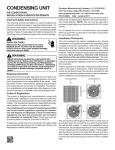
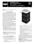
This unit is for outdoor installation only. It cannot be
completely enclosed. Refer to Figure 1 for clearances
from the sides of the unit to full walls and other objects.
Minimum clearances are required to avoid air recirculation and keep the unit operating at peak efficiency. A
minimum six inch clearance is required on one side of the
unit, and a minimum of twelve on two other sides. The
remaining side of the unit must be unrestricted. Ensure
that there is at least five feet clearance above the unit.
These minimum clearances do not guarantee adequate
service access. Sufficient clearances for servicing the
unit(s) must be provided.
Keep the unit as upright as possible. Laying the unit on its
side or top could cause equipment damage.
Clearances and Accessibility
DO NOT locate the unit:
–
–
–
–
Directly under a vent termination for a gas appliance.
Within three feet of a clothes drier vent.
Where water may rise into the unit.
Where the noise would prove to be a nuisance to the
customer (i.e. windows, patios, decks, etc.)
AVOID:
– Direct tubing contact with water pipes, ductwork, floor
joists, wall studs, floors, and walls.
– Suspending refrigerant tubing from joists and studs
with rigid wire or straps that would come in contact with
tubing.
DO locate the unit:
– In accordance with the minimum clearances described
in Figure 1.
– To minimize the length of refrigerant piping required.
– To provide adequate service clearances.
– On a level concrete pad (or other sturdy, weather
resistant platform).
– Isolated from the building structure to avoid transmission of vibrations.
If installing two or more units at the same location, allow at
least 24 inches between the units when using the 6”-12”12” guidelines in Figure 1. The space between two units
may be reduced to 12” if the clearances in Figure 1 are
increased to 12”-24”-24”.
MINIMUM CLEARANCES
12"
5'
12"
SIDE VIEW
DO:
– Leave slack between structure and unit to absorb
vibration.
– When passing refrigerant tubes through the wall, seal
the opening with RTV or a pliable silicon-based caulk.
Figure 1 - Clearances
4
6"
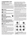
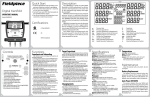
Refrigerant Piping
Rooftops Installations Only
OUTDOOR WALL
Place the unit on a level, weather resistant platform. Be sure
the roof will support the weight of the unit and platform. For
approximate unit weight, see the Product Data Book applicable to your model*. If in doubt about the adequacy of the
roof, it is your responsibility to contact a qualified architect
or structural engineer before installing the unit.
INDOOR WALL
CAULK
LIQUID TUBE
VAPOR TUBE
INSULATION
THROUGH THE WALL
TXV Installation
JOIST
HANGER STRAP
(AROUND VAPOR
TUBE ONLY)
Install only the factory-approved TXV kit specified on the
service label. DO NOT USE AN R-22 TXV. Install the TXV
according to the instructions included in the kit.
INSULATION
VAPOR TUBE
WITH FACTORY-MATCHED INDOOR COILS
Install factory-recommended evaporator coils as listed in
the sales literature and ARI.
IMPORTANT: If the unit is to be installed on a system with
a TXV metering device, remove indoor coil piston
(orifice) to avoid damaging the unit.
1" MIN.
LIQUID TUBE
SUSPENSION
Figure 2 - Connecting Tubing Installation
Application Note
Refrigerant Vapor
and Liquid Lines Routing
For proper performance, the indoor equipment and ductwork must be adequate for moving about 400 CFM of
indoor air for every ton of cooling capacity to be installed.
If they are not, modify the ductwork or indoor equipment
accordingly.
All of the vapor line must be insulated. The insulation must
include a vapor barrier.
The liquid line must be outside the vapor line insulation.
If part of the liquid line must run through an area that will be
hotter than 120°F, then that portion of the liquid line must
be insulated.
Refrigerant Vapor Line Sizing
See the outdoor unit Product Data Book applicable to your
model* for required tubing sizes. Using smaller vapor lines
may decrease performance up to 10%. These sizes are
suitable for line lengths of fifty feet or less. It also assumes
that the indoor coil will not be more than forty feet above or
below the outdoor unit for single stage units and not more
than 25 feet below the condenser for two-stage units. Longer
runs and greater lifts are not recommended. If a run of more
than fifty feet is required, refer to the Remote Cooling Service
Manual or contact your distributor for assistance.
Avoid burying refrigerant lines. If you must bury them, first
dig the trench so it gradually slopes toward the compressor
(at least 1 inch per 10 feet). Then, insulate the liquid and
suction lines separately. Enclose all underground portions
of the refrigerant lines in waterproof material (conduit or
pipe). If the lines must pass under or through a concrete
slab, be sure they are adequately protected.
•
•
R-410A Installation Considerations
Seal the holes where the refrigerant piping enters
the building.
Be careful not to kink or dent the refrigerant lines.
Kinked or dented lines will cause poor performance
or compressor damage.
NOTE: The service valve connections are oriented at a 45°
angle to the unit. Either side of the unit adjacent to the
valves can be conveniently located toward the house.
Drain any residual mineral oil from the existing system and
line sets. Pay particular attention to low areas where oil
may collect. Traps must be drained of oil. R-410A systems
tolerate only a small amount of mineral oil.
*NOTE: Please contact your distributor or our
website for the applicable product data
book referred to in this manual.
5
Refrigerant Piping
Filter Drier
Sweat Connections
IMPORTANT: To avoid overheating the service valve, TXV
valve, or filter drier while brazing, wrap the component
with a wet rag, or use a thermal heat trap compound as
recommended by the compound manufacturer. Use a
brazing alloy of 2% minimum silver content. Do not use
flux.
The liquid line filter drier is factory-installed. Any time the
refrigeration system has been opened for service, a new
properly-sized filter drier rated for R-410A must be installed.
CAUTION
1. The ends of the refrigerant lines must be cut square,
deburred, cleaned, and be round and free from nicks
or dents. Any other condition increases the chance of
a refrigerant leak.
Do not leave system open to atmosphere any longer
than necessary for installation. The compressor
POE oil is extremely susceptible to moisture
absorption and could cause compressor failure.
Ensure ends of tubing are sealed before and during
installation.
2. During brazing, wrap the component with a wet rag, or
use a thermal heat trap compound recommended by
the compound manufacturer, to avoid overheating the
service valve, TXV valve, or filter drier while brazing.
“Sweep” the refrigerant line with nitrogen or inert gas
during brazing to prevent the formation of copperoxide inside the refrigerant lines. The POE oils used
in R-410A applications will clean any copper-oxide
present from the inside of the refrigerant lines and
spread it throughout the system, this may cause a
blockage or failure of the TXV.
3. After brazing, quench the joints with water or a wet
cloth. This will also help prevent overheating of the
service valve.
4. The paint finish of a filter drier must remain intact after
brazing. If the paint of the steel filter drier has been
burned or chipped, repaint or treat with a rust preventative. This is especially important on suction line filter
driers which are continually wet when the unit is
operating.
6
Safe Refrigerant Handling
While these items will not cover every conceivable situation, they should serve as a useful guide.
WARNING
To avoid possible explosion, injury or death, practice safe handling of refrigerants.
WARNING
Refrigerants are heavier than air. They can “push out” the oxygen in your lungs or in any enclosed space. To avoid
possible death or difficulty in breathing:
•
•
•
•
•
Never sniff a refrigerant.
Never purge refrigerant into an enclosed room or space. In fact, all refrigerants must, BY LAW, be reclaimed.
If an indoor leak is suspected, thoroughly ventilate the area before beginning work.
Liquid refrigerant can be very cold. To avoid possible frostbite or blindness, avoid contact and wear gloves and goggles.
If liquid refrigerant does contact your skin or eyes, get medical help immediately.
Always follow EPA regulations. Never burn refrigerant, as poisonous gas will be produced.
WARNING
To avoid possible explosion:
•
•
•
•
Never apply flame or steam to a refrigerant cylinder. If you must heat a cylinder for faster charging, partially immerse
it in warm water.
Never fill a cylinder more than 80% full of liquid refrigerant.
Never add anything other than R-410A to an R-410A cylinder. R-410A operates at a 50 to 70% higher than standard
R-22 systems. Service equipment used must be listed or certified for R-410A.
Store cylinders in a cool, dry place. Never use a cylinder as a platform or a roller.
WARNING
To avoid possible explosion, use only returnable (not disposable) service cylinders when removing refrigerant from a
system.
•
•
•
Ensure the cylinder is free of damage which could lead to a leak or explosion.
Ensure the hydrostatic test date does not exceed 5 years.
Ensure the pressure rating meets or exceeds 400 lbs.
When in doubt, do not use cylinder.
7
Safe Refrigerant Handling
Frontseating Service Valves
R-410A
MANIFOLD
HIGH SIDE
GAUGE
AND VALVE
LOW SIDE
GAUGE
AND VALVE
WARNING
The gauge ports have a standard hose connection
size. Hoses must be rated to 800 psig. R-410A
manifold gauge set must be used.
800 PSI
RATED
HOSES
CHARGING
CYLINDER
AND SCALE
{
Leak Testing
WARNING
VACUUM PUMP
ADAPTER
TO
UNIT SERVICE
VALVE PORTS
To avoid the risk of fire or explosion, never use
oxygen, high pressure air or flammable gasses for
leak testing of a refrigeration system.
VACUUM PUMP
1. Before testing ensure both hand valves on the gauge
manifold are closed relative to the center port (i.e.,
turned IN all the way.)
Figure 4
Deep Evacuation Method
5000
4500
4000
LEAK IN
SYSTEM
MICRONS
3500
3000
2500
2000
VACUUM TIGHT
TOO WET
1500
1000
VAPOR LINE
SERVICE VALVE
LIQUID LINE
SERVICE VALVE
TIGHT
DRY SYSTEM
500
0
1
2
3
4
5
6
7
MINUTES
Figure 5
Deep Vacuum Graph
WARNING
3. Open the hand valve a minimal amount on the line
coming from the nitrogen cylinder.
4. Open the high pressure valve on the gauge manifold.
Pressurize the refrigerant lines and the indoor coil to 150
psig (1034 kPA). To reach 150 psig, you may need to
further open the hand valve on the nitrogen cylinder.
To avoid possible explosion, the line from the nitrogen
cylinder must include a pressure regulator and a
pressure relief valve. The pressure relief valve must be
set to open at no more than 150 psig.
2. Connect a dry nitrogen cylinder to the center port on the
gauge manifold.
8
Safe Refrigerant Handling
EVACUATE
WARNING
BREAK VACUUM WITH DRY NITROGEN
To avoid possible explosion or equipment damage, do
not exceed 150 psig when pressure testing.
WAIT
5. Close the valve on the nitrogen cylinder and disconnect
it from the gauge manifold.
6. Check for leaks. Apply a soap solution on all connections and joints. If you see bubbles, you have a leak.
Mark these locations.
NOTE: If you use an electronic leak detector to test for
leaks, ensure the electronic leak detector used is
capable of sensing HFC-type refrigerants. Also, add a
trace of R-410A to the system (if permitted by current
EPA regulations) before testing.
7. Using the gauge manifold, carefully release the nitrogen
from the system. If leaks are found, repair them. After
repair, repeat the above pressure test. If no leaks exist,
proceed to system evacuation.
EVACUATE
BREAK VACUUM WITH DRY NITROGEN
WAIT
EVACUATE
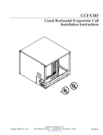
System Evacuation
CHECK FOR TIGHT, DRY SYSTEM
(IF IT HOLDS DEEP VACUUM)
Your system is shipped with the valve stems closed and
caps installed. Do not open these valves until the system is
completely evacuated. There are two ways that your system
can be evacuated: the Deep Vacuum Method or the Triple
Evacuation Method. Use the Triple Evacuation Method when
the vacuum pump being used will only pump down 28 inches
of mercury vacuum and your system does not contain liquid
water; otherwise, use the following method.
CHARGE SYSTEM
Figure 6 - Triple Evacuation Method
6. Open the valve to the thermocouple vacuum gauge.
Evacuate until the gauge reads 250 microns or less.
7. Close the valve to the vacuum pump. Wait five minutes,
then check the pressure on the thermocouple vacuum
gauge (Figure 5).
a. If the pressure is not more than 1000 microns, the
system is leak-free and properly evacuated. Proceed
to Step 9.
b. If the pressure rises, but holds at about 2000+ microns, moisture and noncondensibles are still present.
Open the valve to the vacuum pump, and go back to
Step 7.
c. If the pressure rises above 5000 microns, a leak is
present. Go back to “Leak Testing” section above.
8. Close the valve to the thermocouple vacuum gauge.
Close the valve to the vacuum pump. Shut off the pump.
Triple Evacuation Method
1. Pump system down to 28 inches of mercury and allow
pump to continue operating for an additional 15 minutes.
2. Close manifold gauge valves and shut off vacuum pump.
3. Connect a nitrogen cylinder and regulator to system and
open until system pressure is 2 psig.
4. Close manifold valves and allow system to stand for one
hour. During this time, dry nitrogen will be able to diffuse
throughout the system absorbing moisture.
5. Repeat this procedure as indicated in Figure 6. System
will then be free of any contaminants and water vapor.
Deep Vacuum Method
1. Connect the vacuum pump, R-410A manifold set with
vacuum hoses, and charging cylinder as shown. Ensure
the vacuum pump used is capable of pulling a vacuum of
250 microns. Begin with all valves fully closed.
2. Confirm proper pump and gauge operation. Open the
shutoff valve which leads to the high vacuum gauge
manifold. Start the pump. When the compound gauge
(low side) reading drops approximately 29 inches of
vacuum, open the valve to the thermocouple vacuum
gauge and evacuate until the gauge reads 250 microns
or less.
3. Close the valve to the thermocouple vacuum gauge. This
avoids potential gauge damage from “pegging the meter”.
4. Open the high and low side valves on the gauge manifold.
Keeping the valve on the charging cylinder closed, open
the valve on the gauge manifold that leads to the
cylinder.
5. Evacuate the system to about 29 inches Hg as measured by the compound (low side) gauge.
9
Safe Refrigerant Handling
Line Set Refrigerant Charge
Factory Charge Release Into System
Following evacuation of the low side, add additional R-410A
to the line set, if needed. The unit is factory-charged to
include a system with a 3/8” x 15’ liquid line. This is an 8 oz.
allowance. If additional charge is needed, add this prior to
releasing the factory charge into the low side. If less charge
is needed, recover the excess R-410A during final charge
adjustment. Use the factors below to determine the installed
liquid line charge needed.
1. Remove the service port caps and valve bonnets.
2. Use a male hex head wrench (3/16” for liquid, 5/16” for
suction) to carefully open the suction and liquid valve
stem on the unit. These valves do not back seat. OPEN
EACH VALVE ONLY UNTIL THE TOP OF THE STEM IS
1/8” FROM THE RETAINER. TO AVOID LOSS OF
REFRIGERANT, DO NOT APPLY PRESSURE TO THE
RETAINER.
Once electrical connections are made, the sytem is ready
for startup.
1/4” OD LIQUID LINE = .20 oz. per foot
5/16” OD LIQUID LINE = .36 oz. per foot
3/8” OD LIQUID LINE = .55 oz. per foot
1/2” OD LIQUID LINE = 1.07 oz. per foot
IMPORTANT: Use only refrigerant which is certified to meet
ARI Standard 700. Used refrigerant may cause compressor
damage, and will void the warranty. (Most portable machines
cannot clean used refrigerant well enough to meet this ARI
Standard.)
NOTE: R-410A refrigerant cylinders contain a dip tube which
allows liquid refrigerant to flow with the cylinder in an upright
position. R-410A refrigerant should be charged in the upright
position with the liquid gradually metered into the unit.
10
Electrical Connections
WARNING
To avoid personal injury or death due to electrical shock, disconnect the electrical power before servicing or
connecting the unit. Wiring must conform with NEC or CEC and all local codes.
WARNING
To avoid the risk of fire or equipment damage, use only 75°C minimum-rated copper conductors.
WARNING
Consult the National Electrical Code or a qualified electrician for proper wire size. Undersized wires could cause poor
equipment performance, equipment damage, or fire.
WARNING
To avoid personal injury or death due to electrical shock, wiring to the unit must be properly polarized and grounded.
Local codes will usually require that a disconnect switch be
located near the unit. Do not locate the disconnect switch on
the unit itself.
The wiring diagram for this unit can be found on the control box
door. Refer to Figures 7 and 7a for field wiring connections.
RUN CAP
RUN CAP
TIME DELAY
HIGH VOLTAGE
CONNECTION
LOW VOLTAGE
CONNECTION
Figure 7a
RTC/RTG Unit Control Panel
LOW VOLTAGE
CONNECTION
HIGH VOLTAGE
CONNECTION
Figure 7
RSC/RSG Unit Control Panel
11
Electrical Connections
Wiring
Wire size is important to ensure proper unit operation. The size must be sufficient to carry the minimum circuit ampacity
listed on the unit serial data plate. We recommend sizing the wires to limit the voltage drop to a maximum of 2% from the
main breaker or fuse panel to the outdoor unit. Consult the NEC, CEC, and all local codes to determine the correct wire gauge
and necessary length of run for proper wiring.
1. To connect unit to power supply, route the power supply and ground wires through the high voltage entrance in the unit.
2. Connect the ground wire to the ground lug and power supply wires to the contactor.
LOW VOLTAGE WIRING CONNECTIONS
Low voltage wiring for the two-stage remote air conditioner depends on the thermostat used and the number of thermostat
wires run between the indoor unit (furnace or blower) and the remote. For kit requirements, see Table 1; for low voltage wiring
with kits see Figures 10, 11, and 12.
Thermostat
Number of Wires
to Remote
Kit
Quantity
Single-Stage
2
3
TSRK01
TSRK01
2
1
Two-Stage
2
3
TSTWK01
none
1
none
Table 1
VARIABLE SPEED APPLICATIONS
Refer to the Installation Instructions supplied with the indoor furnace/air handler unit for specific wiring connections and indoor
unit configuration.
Consult the instructions packaged with the thermostat for mounting and location instructions. RSG unit wiring connections
for a two-stage thermostat with three wires to remote are shown in Figures 8 and 9. Figures 10, 11, and 12 refer to the
conditions described in Table 1. NOTE: The instructions included with your thermostat may include “typical wiring” for other
types of indoor equipment.
12
Electrical Connections
RSC CONDENSER
C/X
ROOM THERMOSTAT
C
Y
W
Y
G
#18 GA. 5 WIRES
R
INDOOR UNIT (SEE NOTE 2)
R
G
RED
GREEN
R
R
G
G
W
W
BL
C
SEE
NOTE 1
#18 GA. 2 WIRES
W
WHITE
BL
BLUE
Figure 8
Low Voltage Wiring Diagram for Cooling Unit with
One Stage Heat and One Stage Cool Thermostat
#18 GA. 7 WIRES
RSG CONDENSER
Y/Y2
YL0/Y1
C/X
ROOM THERMOSTAT
Y1 Y2
C W2 G
R W1
MBE
(SEE NOTE 2)
RED
GREEN
WHITE
BROWN
BLUE
Y/Y2
YL0/Y1
YELLOW
PURPLE
BLUE
YL0/Y1
Y/Y2
PURPLE
YELLOW
#18 GA. 3 WIRES
Figure 9
Low Voltage Wiring Diagram for Cooling Unit with
Two-Stage Heat and Two-Stage Cool Thermostat
COLOR CODES
NOTES:
R - RED
Y - YELLOW
BL-BLUE
BR-BROWN
O - ORANGE
W - WHITE
G - GREEN
P - PURPLE
1) TERMINAL BLOCK MARKINGS ARE FOR AMANA®
BRAND AIRHANDLERS.
2) REFER TO INSTALLATION INSTRUCTIONS SUPPLIED
WITH THE INDOOR FURNACE/AIR HANDLER UNIT
FOR SPECIFIC WIRING CONNECTIONS AND INDOOR
UNIT CONFIGURATION.
13
Electrical Connections
RSG REMOTE
CONDENSING
UNIT
4
Y1
5
2
1
Y2
R1
R2
3
B
TSRK01
A
2
B
NO
B
1
NC
B
C
A
C
H
F
YLO
T2
T1
L2
L1
Y
B/C
G
R
W1
W2
SINGLE STAGE
THERMOSTAT
Y
C
G
R
W
Y/Y2
YLO/Y1
C/X
INTEGRATED
FURNACE
CONTROL
FURNACE
Figure 10
Single-Stage Thermostat with Three Low Voltage Wires to Remote (One [1] TSRK01 Kit Required)
RSG REMOTE
CONDENSING
UNIT
TSRK01
4
5
2
1
Y1
3
Y2
R1
R2
2
NO
B
1
A
B
NC
C
B
B
C
H
YLO
A
F
T2
Y
B/C G
R
W1
W2
SINGLE STAGE
THERMOSTAT
T1
Y
L2
G
R
W
L1
Y/Y2
TSRK01
2
YLO/Y1
NO
1
NC
C
C
C/X
INTEGRATED
FURNACE
CONTROL
FURNACE
Figure 11
Single-Stage Thermostat with Two Low Voltage Wires to Remote (Two [2] TSRK01 Kits Required)
WARNING
The TSRK01 adjustable DELAY ON timer settings in the Figure 11 configuration (above) MUST be set the same for
proper operation. Failure to do so will lead to improper operation and premature failure.
14
Electrical Connections
THERMOSTAT
Y/Y2 YL0/Y1
C
G
R
W1
W2
TSTWK01
DIODE
To Y on
TSTWK01 Board
To Common TSTWK01 Board
2
1
Y
RSG REMOTE
CONDENSING
UNIT
5
3
Y1
Y2
R1
To Ground
C
4
R2
To Common
on TSTWK01 Board
C Y
To Common
TSTWK01
Board
TSTWK01
BOARD
C
H
FURNACE
PWR Y2 Y1
F
PWR Y2 Y1
Y2
24 V
T2
T1
L2
L1
Y1
C
G
R
W1 W2
Y/Y2
YLO/Y1
230 V
C/X
INTEGRATED
TSTWK01
TRANSFORMER
FURNACE
CONTROL
Figure 12
Two-Stage Thermostat with Two Low Voltage Wires to Remote (One [1] TSTWK01 Kit Required)
OFF
W1
HEAT
Typical wiring for a gas furnace is shown in Figure 13. The
thermostat instructions may include “typical wiring” for other
types of indoor equipment. Consult the instruction packaged with the thermostat for mounting and location instructions.
GAS VALVE
AUTO
COOL
CC
L2
Y
AUTO
ON
6. Check all factory wiring connections to ensure none
were loosened during shipping and handling.
40 VA
TRANS.
G
L1
R
ROOM THERMOSTAT
NOTE: Some indoor furnaces for cooling operation will
require that fan relay and/or a 40VA transformer be added.
For proper cooling performance, the indoor equipment and
ductwork must be capable of moving 400 CFM of indoor air for
every ton of cooling capacity to be installed. If it is not, modify
the ductwork or indoor equipment accordingly.
Fan
Relay
L1
HI
L2
BLOWER
MOTOR LO
FAN
SW.
For best performance, low stage cooling airflow should be
60%-75% of high stage cooling speed.
Figure 13 - Gas Furnace Wiring (typ.)
15
Electrical Connections
Figure 14 Low Voltage Wiring Diagram for Heat Pump with
Single-Stage Cool and Two-Stage Heat Thermostat
RTC HEAT PUMP
C W2 O
B
L
A
C
K
B
L
U
E
Y
O
R
A
N
G
E
TYPICAL H/P ROOM THERMOSTAT
Y
R
Y
E
L
L
O
W
O
C W2 G
R
#18 GA. 7 WIRE
E
R
E
D
R
Y
INDOOR UNIT (SEE NOTE 2)
R
R
R
RED
G
G
G
GREEN
BR
W
W
W2
WHITE
BL
BL
C
O
W
BL
#18 GA. 5 WIRE
BLUE
SEE NOTE #1
Figure 15 Low Voltage Wiring Diagram for Heat Pump with
Two-Stage Cool and Three-Stage Heat Thermostat
RTG HEAT PUMP
Y2 Y1 O W2 C
P
U
R
P
L
E
Y
E
L
L
O
W
O
R
A
N
G
E
B
L
U
E
B
L
A
C
K
TYPICAL H/P ROOM THERMOSTAT
Y1 Y2
R
O
C W2 G
R
E
#18 GA. 8 WIRES
MBE
R
E
D
(SEE NOTE 2)
RED
GREEN
WHITE
BROWN
BLUE
ORANGE
Y/Y2
YL0/Y1
YELLOW
PURPLE
RED
BLUE
WHITE
ORANGE
YL0/Y1
Y/Y2
PURPLE
YELLOW
#18 GA. 6 WIRES
NOTES:
COLOR CODES
R - RED
Y - YELLOW
BL-BLUE
BR-BROWN
O - ORANGE
W - WHITE
G - GREEN
P - PURPLE
1) TERMINAL BLOCK MARKINGS ARE FOR AMANA®
BRAND AIRHANDLERS.
2) REFER TO INSTALLATION INSTRUCTIONS SUPPLIED
WITH THE INDOOR FURNACE/AIR HANDLER UNIT
FOR SPECIFIC WIRING CONNECTIONS AND INDOOR
UNIT CONFIGURATION.
16
System Startup
CAUTION
To prevent compressor damage or personal injury:
•
•
•
•
Do not overcharge system with refrigerant.
Do not operate unit in a vacuum or at negative pressure.
Do not disable the low pressure switch.
Use care when handling scroll compressors, dome temperatures could be hot.
CAUTION
To prevent personal injury, wear safety glasses, protective clothing, and gloves when handling refrigerant.
CAUTION
To prevent personal injury, carefully connect and disconnect manifold gauge hoses. Escaping liquid refrigerant can
cause burns. Do not vent refrigerant to atmosphere. Recover during system repair or final unit disposal
IMPORTANT!
During all installation and service work, follow all regulations of the Environmental Protection
Agency (EPA). This system uses R-410A - an HFC [Hydrofluorocarbon]. Violation of EPA
regulations may result in fines or other penalties.
Never operate the compressor with the suction valve closed to “test the compressor’s
pumping efficiency”. In some cases, this can result in serious compressor damage and loss
of warranty coverage. The TSTWK01 kit requires both low voltage and high voltage wiring
connections be made.
1. If manifold gauge set hoses are not connected, connect
the gauge hoses.
5. Check and record low stage liquid pressure at the
service valve.
6. Two-Stage Thermostat - adjust thermostat set point
well below room temperature.
Single-Stage Thermostat - wait for the delay relay to
activate.
7. Wait 10 minutes and record high stage liquid pressure
at the service valve. The high stage liquid pressure
should be noticeably higher than the low stage liquid
pressure at the service valve.
If the pressures are identical, the compressor did not
switch from low to high stage. Verify thermostat differential on low stage, wiring, etc. and recheck unit again.
2. Close electrical disconnects to energize system.
3. If the outdoor temperature is 60°F or higher, set room
thermostat to COOL and fan control to ON or AUTO.
For the Two-Stage Thermostat, set temperature control until the low stage cooling is activated (Typically 1°F
below room temperature).
For the Single-Stage Thermostat, set the adjustable
ON DELAY timer on all adjustable time relays to 15
minutes. The adjustable time relay is shipped with the
TSRK01 kit.
4. Operate unit for 10 minutes.
17
System Startup
If the system is performing properly, reinstall the service port
caps and the valve bonnets. With the valve opened, the valve
bonnet is the primary seal against refrigerant leaks. Apply
two (2) drops of clean oil to the cap threads, allowing the oil
to run down to the inner cap seal surface. Close caps fingertight then tighten cap an additional two to three hex flats.
NOTE: Subsequent opening and replacing of the cap will
require only 1/2 to 1 hex flat. See the table below for the
torque required for an effective seal on the valve bonnet (1/6
turn past finger-tight).
Low Stage Final Charge Adjustment
Run the remote on low stage cooling for 10 minutes until
refrigerant pressures stabilize. Follow the guidelines and
methods below to check unit operation and ensure that the
refrigerant charge is within limits:
•
•
•
•
•
Obtain the service data table for the outdoor unit
located on the label inside the control box cover.
Measure the suction and liquid pressures at the
service valves, the liquid line temperature at the
outdoor unit, and the outdoor unit amps. Measure the
outdoor ambient temperature, and the indoor wet and
dry bulb temperatures (see Product Data Book applicable to your model* expanded performance data).
Determine the required subcooling from the data label.
See the service manual for the proper subcooling
adjustments required for long line sets or coil elevations (systems with a TXV only).
Add R-410A charge when the liquid subcooling is
more than two (2) degrees below requirement, and
recover charge when two degrees above the requirement. See the subcooling reference table in the
appendix to determine the liquid temperature needed
to obtain the target subcooling at the liquid pressure
reading.
Compare suction pressure with performance data.
(Suction pressure depends on which coil model is
installed, and the indoor air flow and wet bulb).
Tubing Size
•
3/8
10.0
3/4, 7/8
16.0
After closing the valve bonnet, perform a final refrigerant leak
test on the valves and sweat connections. Return the room
thermostat to the desired settings.
Final Checks
•
•
•
•
NOTE: Do NOT adjust refrigerant based on suction pressure,
unless there is a gross undercharge.
•
Torque (Foot-Pounds)
Compare the low stage liquid pressure to the specification data. Liquid pressure depends on the suction
pressure, outdoor temperature, and the liquid
subcooling. Make charge adjustments based on the
required subcooling determined above.
Compare the low stage outdoor unit amps to the
specification data. The amp reading tracks with the
liquid pressure.
Adjust set point of two-stage thermostat to activate
high stage cooling or, in the case of a single -stage
thermostat, wait for the time delay relay to activate
high stage cooling.
Measure the liquid pressures at the service valve, the
liquid line temperature at the outdoor unit and the
amperage of the outdoor unit. For high stage cooling,
the subcooling, liquid pressure, and amps should be
all be higher on high stage cooling when compared to
low stage cooling. Do not adjust charge to change
the subcooling on high stage. Charge adjustments must only be made under low stage cooling.
Ensure all wiring and tubing are secure in the unit
before adding panels and covers.
Securely fasten all panels and covers.
Leave Owner’s Manual with owner. Explain system
operation and periodic maintenance requirements
outlined in manual.
Fill out dealer installation checklist and place in
customer file.
Troubleshooting
(QUALIFIED SERVICER ONLY)
When troubleshooting, check for clean coils, clean filter(s),
and proper airflow. Indoor airflow should be 350 to 450 CFM
per ton of cooling, based on the size of the outdoor unit. The
most common way of establishing indoor airflow is heating
temperature rise. Indoor airflow will then be (heating output
of equipment) / (1.1 x temp. rise). In other cases, measurement of external static pressure is helpful. For details, see
the Installation Manual for your indoor equipment.
If further information is needed, see the Remote Cooling
Service Manual.
*NOTE: Please contact your distributor or our
website for the applicable product data book
referred to in this manual.
18
System Startup - RTG Units Only
The defrost board function will speed up when the test pins
are connected. Time between defrosts will be 14 seconds.
Defrost time will be 6.5 seconds.
Defrost System
To avoid electric shock or death, disconnect the power
before changing the defrost time cycle or servicing the unit.
After servicing is completed, disconnect the power, move the
Defrost Time Select Tab back to 30, 60, or 90, remove jumper
wire on DFS, and reconnect the power.
This unit is equipped with a time/temperature defrost board.
Defrosting of the outdoor coil is determined by both coil
temperature and compressor run time. Adjustment can be
changed as required. There are 30, 60, and 90 minute
settings available. Adjust only if geographical conditions,
outdoor humidity, or other adverse conditions make it necessary. The maximum defrost time is 10 minutes. Most
defrost cycles are shorter.
NOTES:
1. If the time select tab remains in TEST position for five (5)
minutes, the control will ignore TEST mode and assume
a normal defrost cycle. To override this, briefly remove
and then replace the select tab.
2. When the unit starts the defrost cycle, quickly remove
the time select tab to allow normal defrosting and defrost
termination to proceed. The select tab can be reconnected to TEST to repeat the defrost cycle, or the tab
can be placed in the desired time setting. (Jumping both
test pins with a small insulated screw driver will also
work.)
Run Time Adjustment
1. Disconnect power to outdoor unit.
2. Move the defrost time adjustment pin from 30 minutes to
60 minutes or 90 minutes as required.
3. Reconnect the electric power.
Rapid Advance
When servicing the unit, it may be necessary to rapidly
advance the system through a defrost cycle. To perform a
rapid advance:
1. Ensure the 24VAC power is ON.
2. Place the defrost time adjustment pin on “TEST”.
NOTE: If the outdoor coil temperature is above 30°F,
place a jumper wire between the “DFS” terminals (defrost sensor) on the defrost control before placing defrost
time adjustment pin on “TEST”.
3. Reconnect electrical power to outside unit.
4. Place the system into heating operation.
19
System Checklist
1
Is the system clearly marked as containing R-410A refrigerant? (Labels are
located on both the indoor coil case and remote unit.)
2
Does the condenser fan blade rotate freely, and is it tight on the shaft?
3
Does the refrigerant tubing flex freely and not touch another tube to cause rub
through?
4
Are both indoor and outdoor sections level?
5
Are the units properly supported?
6
Is outdoor section properly located on concrete base or equivalent?
7
Are the refrigerant lines correctly installed according to the relative position of the
outdoor and indoor sections?
8
Is the refrigerant tubing properly supported by isolation hangers?
9
Is the system completely free of refrigerant leaks?
10 Has the system been properly evacuated?
11 Does the system have the correct R-410A refrigerant charge?
12
Is the outdoor unit protected by the correct size time delay type fuses or
breakers in the indoor power box?
13 Are the power supply wires to units the correct size?
14 Are all electrical connections tight?
15 Does the compressor sound normal?
16
Check the amperage on the indoor blower motor. Is it within the limits shown on
the nameplate of the motor?
17 Are all access panels installed and secured?
18 Do controls function properly?
Check the voltage with unit running. Does it check within the tolerance of 207 to
19 253V for 230V, or 198 to 228V? If using 208V power indoors, have you modified
the transformer wiring as necessary?
20 Has the air flow across the indoor coil been checked and adjusted?
21
Has the air distribution system been balanced? Are all grilles, diffusers, and
dampers properly adjusted and locked?
22 Has the system operated at least 30 minutes before leaving the job?
23 Does the owner understand the operation of the unit and the thermostat?
24 Does the owner know where the filters are located?
25 Does the owner know when and how the filter(s) should be cleaned or changed?
26 Have the registration cards been filled out and mailed?
27 Does the owner know whom to call for service?
28 Has the User's Guide been filled out and left with the owner?
20
R-410A QUICK REFERENCE GUIDE
• R-410A refrigerant operates at 50-70 percent higher pressures than R-22. Ensure that the servicing equipment
and replacement components used are designed to operate with R-410A.
• R-410A refrigerant cylinders are rose colored.
• R-410A refrigerant cylinders have a dip tube which allows liquid to flow out of cylinder in upright position.
NOTE: Recovery cylinder service pressure rating must be 400 psig, DOT RBA400 or DOT BW400.
• R-410A systems should be charged with liquid refrigerant. Use a commercial type metering device in the
manifold hose.
• Manifold sets should be 800 psig high side and 250 psig low side with 550 psig low side retard.
• Use hoses with 800 psig service pressure rating.
• R-410A requires a different set of gauges than those used for R-22.
• R-410A requires Amana®-brand matched indoor/outdoor systems.
• Leak detectors should be designed to detect HFC refrigerant.
• R-410A, as with other HFCs, is only compatible with POE oils.
• POE oils absorb moisture rapidly. Do not expose oil to atmosphere.
• Vacuum pumps will not remove moisture from oil.
• An R-410A listed liquid line filter drier is required on every unit.
• Do not use liquid line filter driers with rated working pressures less than 600 psig.
• Do not install a suction line filter drier in liquid line.
• Wrap all filter driers and service valves with wet cloth when brazing.
• Do NOT use an R-22 TXV.
• If indoor unit is equipped with an R-22 TXV, it must be changed to an R-410A TXV.
• Never open system to atmosphere while it is under a vacuum.
• When system must be opened for service, evacuate then break vacuum with dry nitrogen and replace filter driers.
• Do not vent R-410A into the atmosphere.
• Do not use capillary tube coils.
• Observe all warnings, cautions, and bold text.
21
Pressure vs. Temperature Chart
PSIG
°F
12 -37.7
14 -34.7
16 -32.0
18 -29.4
20 -36.9
22 -24.5
24 -22.2
26 -20.0
28 -17.9
30 -15.8
32 -13.8
34 -11.9
36 -10.1
38 -8.3
40 -6.5
42 -4.5
44 -3.2
46 -1.6
48
0.0
50
1.5
52
3.0
54
4.5
56
5.9
58
7.3
60
8.6
62 10.0
64 11.3
66 12.6
68 13.8
70 15.1
72 16.3
74 17.5
76 18.7
78 19.8
80 21.0
82 22.1
84 23.2
86 24.3
88 25.4
90 26.4
92 27.4
94 28.5
96 29.5
98 30.5
100 31.2
102 32.2
104 33.2
106 34.1
108 35.1
110 35.5
112 36.9
PSIG
114
116
118
120
122
124
126
128
130
132
134
136
138
140
142
144
146
148
150
152
154
156
158
160
162
164
166
168
170
172
174
176
178
180
182
184
186
188
190
192
194
196
198
200
202
204
206
208
210
212
214
°F
37.8
38.7
39.5
40.5
41.3
42.2
43.0
43.8
44.7
45.5
46.3
47.1
47.9
48.7
49.5
50.3
51.1
51.8
52.5
53.3
54.0
54.8
55.5
56.2
57.0
57.7
58.4
59.0
59.8
60.5
61.1
61.8
62.5
63.1
63.8
64.5
65.1
65.8
66.4
67.0
67.7
68.3
68.9
69.5
70.1
70.7
71.4
72.0
72.6
73.2
73.8
PSIG
216
218
220
222
224
226
228
230
232
234
236
238
240
242
244
246
248
250
252
254
256
258
260
262
264
266
268
270
272
274
276
278
280
282
284
286
288
290
292
294
296
298
300
302
304
306
308
310
312
314
316
°F
74.3
74.9
75.5
76.1
76.7
77.2
77.8
78.4
78.9
79.5
80.0
80.6
81.1
81.6
82.2
82.7
83.3
83.8
84.3
84.8
85.4
85.9
86.4
86.9
87.4
87.9
88.4
88.9
89.4
89.9
90.4
90.9
91.4
91.9
92.4
92.8
93.3
93.8
94.3
94.8
95.2
95.7
96.2
96.6
97.1
97.5
98.0
98.4
98.9
99.3
99.7
PSIG
°F
318 100.2
320 100.7
322 101.1
324 101.6
326 102.0
328 102.4
330 102.9
332 103.3
334 103.7
336 104.2
338 104.6
340 105.1
342 105.4
344 105.8
346 106.3
348 106.6
350 107.1
352 107.5
354 107.9
356 108.3
358 108.8
360 109.2
362 109.6
364 110.0
366 110.4
368 110.8
370 111.2
372 111.6
374 112.0
376 112.4
378 112.6
380 113.1
382 113.5
384 113.9
386 114.3
388 114.7
390 115.0
392 115.5
394 115.8
396 116.2
398 116.6
400 117.0
402 117.3
404 117.7
406 118.1
408 118.5
410 118.8
412 119.2
414 119.6
416 119.9
418 120.3
*Based on ALLIED SIGNAL Data
22
PSIG
°F
420 120.7
422 121.0
424 121.4
426 121.7
428 122.1
430 122.5
432 122.8
434 123.2
436 123.5
438 123.9
440 124.2
442 124.6
444 124.9
446 125.3
448 125.6
450 126.0
452 126.3
454 126.6
456 127.0
458 127.3
460 127.7
462 128.0
464 128.3
466 128.7
468 129.0
470 129.3
472 129.7
474 130.0
476 130.3
478 130.7
480 131.0
482 131.3
484 131.6
486 132.0
488 132.3
490 132.6
492 132.9
494 133.3
496 133.6
498 133.9
500 134.0
502 134.5
504 134.8
506 135.2
508 135.5
510 135.8
512 136.1
514 136.4
516 136.7
518 137.0
520 137.3
PSIG
°F
522 137.6
524 137.9
526 138.3
528 138.6
530 138.9
532 139.2
534 139.5
536 139.8
538 140.1
540 140.4
544 141.0
548 141.6
552 142.1
556 142.7
560 143.3
564 143.9
568 144.5
572 145.0
576 145.6
580 146.2
584 146.7
588 147.3
592 147.9
596 148.4
600 149.0
604 149.5
608 150.1
612 150.6
616 151.2
620 151.7
624 152.3
628 152.8
632 153.4
636 153.9
640 154.5
644 155.0
648 155.5
652 156.1
656 156.6
660 157.1
664 157.7
668 158.2
672 158.7
676 159.2
680 159.8
684 160.3
688 160.8
692 161.3
696 161.8
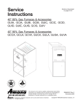
Required Liquid Line Temperature
REQUIRED LIQUID LINE TEMPERATURE
REQUIRED SUBCOOLING TEMPERATURE (°F)
10
12
14
16
LIQUID PRESSURE
AT SERVICE VALVE (PSIG)
8
189
195
202
58
60
62
56
58
60
54
56
58
52
54
56
50
52
54
48
50
52
208
215
64
66
62
64
60
62
58
60
56
58
54
56
222
229
236
68
70
72
66
68
70
64
66
68
62
64
66
60
62
64
58
60
62
243
74
72
70
68
66
64
251
259
266
76
78
80
74
76
78
72
74
76
70
72
74
68
70
72
66
68
70
274
283
291
299
308
317
326
335
345
354
364
374
384
395
406
416
427
82
84
86
88
90
92
94
96
98
100
102
104
106
108
110
112
114
80
82
84
86
88
90
92
94
96
98
100
102
104
106
108
110
112
78
80
82
84
86
88
90
92
94
96
98
100
102
104
106
108
110
76
78
80
82
84
86
88
90
92
94
96
98
100
102
104
106
108
74
76
78
80
82
84
86
88
90
92
94
96
98
100
102
104
106
72
74
76
78
80
82
84
86
88
90
92
94
96
98
100
102
104
439
116
114
112
110
108
106
450
462
118
120
116
118
114
116
112
114
110
112
108
110
474
122
120
118
116
114
112
486
499
511
124
126
128
122
124
126
120
122
124
118
120
122
116
118
120
114
116
118
23
18
©2004 Goodman Company, L.P.
24
Effective: November 2004