1
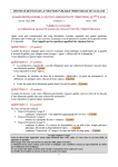
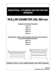
Chest heated ironers CL300/1800 UL300/1800 Technical specifications Installation instructions Operating instructions Maintenance Instruction manual Gas heating Part No. D1510EN IRONER 300 English 2 IRONER 300 FOREWORD. This manual contains information on installation, operation and maintenance. The operator should read this manual carefully and become familiar with the machine regulations before the machine is commissioned. In this document we have attempted to answer any questions you may have. For further information or explanation, please contact our after-sales department. This machine was developed only for use in industrial surroundings. The illustrations, drawings and text are as accurate as possible. Discrepancies may occur as a result of technical improvements or special options ordered by you. The design explanations in this manual are intended only for the user of the machine and under NO circumstances may they be disclosed to third parties. This manual will help you get the best out of your machine. Location of serial number plate. Always quote the machine identification number when requesting information or ordering parts. Machine No. plate + CE plate can be found on the front at the bottom right. English 4 IRONER 300 WE CAN’T GIVE ANY WARRANTY TO THE FOLLOWING ELEMENTS: - The padding - The feed bands. - Chains - Oil change. - Transport damage. - Components damaged by poor maintenance. - Spare parts who are placed by a technician who is not trained or schooled by --LACO. English 5 IRONER 300 PART 1 INSTALLATION................................................................................................. 8 1.1 HANDELING OF THE MACHINE. ............................................................................................ 8 1.2 TECHNICAL DATA AND DIMENSIONS. ................................................................................... 9 1.3 INSTALLATION. .................................................................................................................. 10 PART 2 SERVICE INSTRUCTIONS ............................................................................. 12 2.1 GENERAL ............................................................................................................................ 12 2.2 DAILY CHECKPOINTS ......................................................................................................... 12 2.2.1 DAILY CHECKPOINTS BEFORE STARTING ........................................................................... 12 2.2.2 NORMAL USE .................................................................................................................... 12 2.2.3 ABNORMAL USE ................................................................................................................ 13 2.2.4 CONTINUED RISKS WITH THE MACHINE - MEASURES TO TAKE. .......................................... 13 2.3 CONTROL PANEL ................................................................................................................ 13 2.4 OPERATION INSTRUCTIONS ............................................................................................... 14 2.4.1 OPERATIONS INSTRUCTIONS ............................................................................................. 14 2.4.2 ADDITIONAL POINTS. ........................................................................................................ 15 2.5 SECURITY INSTRUCTIONS .................................................................................................. 15 2.6 WHAT TO DO IN EMERGENCY SITUATIONS. ....................................................................... 17 SITUATION 5: ELECTROCUTION ................................................................................................. 17 SITUATION 6: BROKEN PIPES.................................................................................................. 17 PART 3: MAINTENANCE INSTRUCTIONS. ............................................................... 18 3.1 MAINTENAINCE INSTRUCTIONS. ........................................................................................ 18 3.2 TROUBLESHOOTING GUIDE. ............................................................................................... 20 3.2.1 THE MACHINE DOES NOT REACH TEMPERATURE AFTER PRESSING THE START BUTTON. .... 20 3.2.2 MACHINE IS AT TEMPERATURE BUT IRONING BED DOES NOT CLOSE.................................. 20 3.2.3 THE IRONING BED CLOSES BUT THE ROLL DOES NOT TURN ................................................ 21 3.2.4 ROLL SUCTION DOES NOT WORK. ...................................................................................... 21 3.2.5 NO CONTROL VOLTAGE. ................................................................................................... 22 3.2.6 CREASES IN THE LINEN. .................................................................................................... 22 3.3 ADJUSTMENT OFF THE CONTACT. ..................................................................................... 22 3.4 DRIVE FEEDING BELTS. ...................................................................................................... 23 3.4.1 M300................................................................................................................................ 23 3.4.2 D300 ................................................................................................................................ 23 3.5 TEMPERATURE SETTINGS. ................................................................................................. 24 3.6 HOW TO PUT IN THE LINNEN ON A M300 – D300. ............................................................. 25 3.7 THERMO-OIL CHANGE M300 – D300 ................................................................................ 26 3.8 CLEANING OF THE BED. ..................................................................................................... 28 3.9 ROLL PADDING REPLACEMENT.......................................................................................... 29 4.1 ELECTRICAL EQUIPMENT ................................................................................................. 36 4.1.1 ROLL DRIVE. ..................................................................................................................... 36 4.1.2 LIFT BED ........................................................................................................................... 37 4.1.3 ROLL SUCTION DRIVE. ...................................................................................................... 37 4.1.4 FUSES ............................................................................................................................... 38 4.1.5 CONTROL PANEL. .............................................................................................................. 39 4.1.6 OTHER. ............................................................................................................................. 40 English 6 IRONER 300 4.1.7 MONAYEUR ..................................................................................................................... 41 4.1.8 GASBURNER ..................................................................................................................... 42 4.2 MECHANICAL EQUIPMENT ................................................................................................ 43 4.2.1 ROLL DRIVE. ..................................................................................................................... 43 4.2.2 ROLL. ............................................................................................................................... 45 PART 5: APPENDIX ...................................................................................................... 45 5.1 INSTALLATION PLAN .......................................................................................................... 46 English 7 IRONER 300 PART 1 INSTALLATION 1.1 Handeling of the machine. - Lift the machine. - Devide the weight so that the machine does not hang crooked. - Make sure nobody walks under the load.. - Lift the machine carefully and without impacts. Move regularly and without sudden movements. - Put the load on the ground as soon as possible. - Make sure there are no obstacles in the way. English 8 IRONER 300 1.2 Technical data and dimensions. M300/1800 D300/1800 300 mm 1800 mm 1110 mm 2255 mm 815 mm 150°C 185°C 0.18 kW 68 W 16A 300 mm 1800 mm 1110 mm 2255 mm 1400 mm 150°C 185°C 0.18 kW 68 W 16A 2 x 2.5mm² (L+N) + PE ---L1 + L2 Doesn’t works!--0.8 m / min 4 m / min 60kg 2 x 2.5mm² (L+N) + PE ---L1 + L2 Doesn’t works!--0.8 m / min 4 m / min 60kg 60 mm 60 mm °C (Ironing temp 185°C) 100 100 m³/h 150 150 Weight Kg 350kg 350kg Packaging Height Width Depth Noise Decibel 1350 mm 2350 mm 850 mm 60-65dB 1350 mm 2350 mm 850 mm 60-65dB Gas inlet Pressure Min. 20mBar Min. 20mBar Diameter ½” ½” Diameter 80 mm 80 mm °C Min. 260 (Heat resistance pipe) 18 kW Min. 260 (Heat resistance pipe) 18 kW Roll Diameter Length dimensions Height Width Depth Temperature Min Max Roll Suction Mono 230V / 50 Hz Motors Electr. Connection (D curve) Cable section Speed Capacity Vapour outlet Gas outlet Capacity burner Min - 25 Hz Max – 50 Hz Residual moisture 25% Temperature 185°C Diameter kW Max. temperature for nomex is 190°C English 9 IRONER 300 1.3 Installation. 1. The machine has to be unloaded according the regulations. See 1. Transport of the machine. 2. Remove all packing material such as plastics and cardboard. Clean the bed before heating the machine. Use for this no explosive products. Packing material. S. also beige-supplied designs! 3. Electrical connections. Electrical cable connection: 2 x 2.5mm ² (L + N) + PE (230V/50Hz MONO) (L1 + L2 Doesn’t works. You need a grounding!) 4. Gas connection Compare the type of gas (natural gas, propane) with the data on the machine and bear the guidelines in mind. It is important for the gas connections to be set up by an approved specialist to ensure that the installation complies with the standards and guidelines that apply where the machine is installed. The gas connection must correspond to the type of gas specified on the machine plate. The gas pressure for natural gas and propane must be between 20 mBar and 65 mBar. If the pressure exceeds 65 mBar, a gas pressure regulator must be installed upstream of the connection tap. Also consider the diameter of the gas pipe. The machine connection is ½”. If the distance between the gas meter and the machine is over 10 meters, the use of a gas pipe with a larger diameter is recommended (e.g. 1" instead of ½”) Gas connection: ½” Gas valve not included, use certified gas valve. English 10 IRONER 300 5. Attach and isolate completely the suction pipe! (Temperature min. 100°C for vapour outlet and min. 260°C for gas outlet. ). Note: The maximum distance of these pipes is indicated about 5 meters as in enclosed plan. For longer distances one must take a larger diameter (e.g. 125 mm instead of 80 mm or 90 mm.!) The vapour outlet must be completely separate by law to prevent the risk of fire. The vapour outlet should consist of a heat-resistant pipe (min. 100°C). In order to achieve proper operation, this pipe must always be kept as short as possible and must have as few bends as possible. If an outlet channel joins a main channel, the angle of incidence must not exceed 45°. If the distance from the outlet channel is greater than 5 metres, a series fan must be installed further down the outlet channel or the section of the pipe must be increased! e.g. 125 mm instead of 80 mm. Insulate both the gas and steam outlet pipes to prevent fire Note : Failure to comply with the installation guidelines may lead to counter-pressure in the outlet channel which will impair output and quality. 6. Isolate all lines outside of the machine. Protect hot parts where you can burn yourself by contact. 7. Burner adjustment. On startup of the machine on location, burner settings have to be adjusted by an recognized or competent person and be inspected on standards in the concerned region. Before starting the burner, it is necessary to read the enclosed manual of the burner and the gas train. Burner settings also have to be adjusted every 12 months for optimal burning and efficiency, also by a recognized or competent person. The burner must be set so it can burn at a capacity of 18kW. The gas outlet pipe becomes 260°C and must be isolated. There is a hole in the door (side of the burner) where you can check if the burner is working. If the burner is working, then you will see a green light. 8. The machine can be used only in the required industrial surroundings that satisfy the safety and connections rules. 9. The machine is now finished for the work. English 11 IRONER 300 PART 2 SERVICE INSTRUCTIONS 2.1 General - The service life of an ironing machine with a steel ironing bed is approximately 15 years with normal maintenance. This is an estimate. It is not binding. No compensation may be claimed for a shorter service life. Noise level: 60-65 dB depending on speed 2.2 Daily checkpoints 2.2.1 Daily checkpoints before starting - Check the direction of rotation of all motors. Are all safety guards in position and closed? Check the functioning of the finger guard and its correct adjustment. This means the opening between the finger guard and feed bands must not exceed 15 mm. Check the operation of the emergency stop buttons. Before starting, make sure that nobody is in a dangerous area. Check that there are no extraneous objects between the roll and bed of the ironing machine. Check the condition of the padding. Also check the condition of the feed bands. Clean dust from the machine. Check the machine for leaks. 2.2.2 Normal use - - The machine is suitable for ironing all sorts of flat linen such as sheets, drawsheets, towels, pillow cases, handkerchiefs etc. The maximum temperature is 185°. The minimum temperature is 150°. The padding should be adjusted to the operating temperature (nomex max. 190°C). The machine settings for installation, ironing pressure, installation of the padding etc should be in accordance with the regulations described in the manual. The machine must be maintained regularly as described in the manual. Only spare parts supplied by the manufacturer may be used. The manufacturer accepts no liability for defects and accidents due to incorrect use of the machine or spare parts that he has not supplied.. Do not allow any hard parts to turn between the roll and bed. Do not allow any fusible materials to turn in the roll. Take account of all safety regulations. English 12 IRONER 300 2.2.3 Abnormal use - Ironing items that are not flat. Allowing the machine to run empty (without feeding linen). Temperatures in excess of 190°. Cleaning the beds with hard materials (can cause irreparable damage). Working without taking safety precautions. Failure to comply with safety regulations. 2.2.4 Continued risks with the machine - measures to take. All pipes outside the machine for the roll exhaust and burner exhaust, pose a real risk of burns. For this reason, all these pipes must be properly insulated and protected against direct contact. Staff using the machine must be trained in how to handle emergency situations e.g. how to free someone who is trapped, what to do in the event of a fire, breakdown of the machine etc. The hot linen emerging from the machine can cause burns. For this reason, it is necessary to wear personal protection such as gloves when handling the linen. As far as possible, non-flammable materials have been used in the design of the machine. However, flammable materials will still always be present in the form of the padding, feed bands and the oil in the machine. However, the greatest risk is posed by dust. Under certain conditions, dust can create a highly explosive mixture. Therefore it is essential to clean the machine regularly. Also create an equipotential link so that no potential differences arise between the machine and the surrounding metal structures to prevent sparkover. 2.3 Control panel Temperature Settings Start Roll Stop Roll Potentiometer Roll speed English 13 IRONER 300 2.4 Operation instructions 2.4.1 Operations instructions MAIN SWITCH ON IN PRESS OUT OUT PRESS IN START - BED IS PRESSED AGAINST THE ROLL - ROLL TURNS AFTER 4 SEC. - ROLL STOPT IMMEDIATE - BED IS STILL PRESSED AGAINST THE ROLL PRESS FINGER PROTECTION STRIP START - ROLL STARTS AFTER 4SEC STOP - THE BED GOES OPEN - ROLL STOPT IMEDIATE English 14 IRONER 300 The machine can be trained only used by staff with the necessary physical requirements! Note : During the operation of the emergency stop key `S1' all motors as well as the heating of the bed are stopt. For a new start its only possible by turning back the emergency stop key `S1' and again press the start button `S3' Note : After you pressed the finger protection strip the bed remains pressed against the roll, it is therefore to recommend the roll to start as soon as possible or stop the machine completely(otherwise felt burns). 2.4.2 Additional points. - - Run a wax cloth though the ironing machine 2 to 4 times a day to wax the bed. If this is not done, the bed will glide less smoothly and static electricity may occur, resulting in poor ironing quality. Clean the ironing bed regularly with a special cleaning cloth (available as an option with the machine). 2.5 Security instructions Dangerous places What you must not do - Hot bed - Do not move with the hands under that the finger protection strip or between the intake belts. - The entrance of the bed and the roll. - Attempt no parts to withdraw those already are entered. - Hot linnen at the exit of the roller. - Avoid loose clothes, loose hair, bracelets, rings, etc. - Intake wedge of the intake belts. - Never start the machine whitout a screening or collateral inspection of the safety borders of the machine - Drive components. - It is forbidden to climb on the machine. English 15 IRONER 300 Regulations. - Examine daily the working of the different security safety - Teach the personnel as to be behaved in emergencies. - Close loose clothes. Bind loose hair up. No decoration. - With repair and maintenance: Secure the machine before working on it. - With repair on parts, carry safety clothes - Clean the machine only in a cold and switched off condition - Switch off the engine when working on the machine - Read the service manual before working with the machine. - Carry gloves with the treatment of the laundry - Announce immediate damages English 16 IRONER 300 2.6 What to do in emergency situations. Situation 1: Emergency stop fails Stop the machine with the main switch. Check the operation of the emergency stop button and the finger guard regularly as part of preventive maintenance. Situation 2: A person is trapped between the roll and the bed. Press the red stop button or the emergency stop button. The bed will lower from the roll and the trapped person can be released. Call the emergency services and give first aid. Situation 3: Turning with the feed bands. Press the emergency stop button Cut the feed bands. Situation 4: Fire Press the emergency stop button and immediately switch off the power supply. Call the emergency services. Situation 5: Electrocution Immediately disconnect from power supply and only then release the person. Otherwise you run the risk of being electrocuted yourself. Give first aid. Call the emergency services immediately. Situation 6: Broken pipes GAS: Close the gas tap immediately. Open all windows and doors. English 17 IRONER 300 PART 3: MAINTENANCE INSTRUCTIONS. 3.1 Maintenaince instructions. Daily: - Pass a wax cloth (cleaning cloth) through the ironing machine 2 to 4 times a day. (4 times when the linen doesn’t enters smoothly the chest, or when there are creases in the linen.) (1 x wax ± 5min.) - Clean the machine with a vacuum cleaner or with air pressure. (1 person ± 10min.) 12 x per year : - Clean the burner. (1 person ± 20min.) 4 x per year - Clean the suction wings of the drive. (1 person ± 30min.) 2 x per year: - Check chain and tension of feed bands. Every year - Lubricate the chain. (1 person ± 5min.) Every 2 years: - Change thermal oil every 2 year or every 3500 hours. Type: Texaco Texatherm 25 liters. (1 person ± 6 hours) Alternative oil: SYNLUBE TRANSCAL SHELL CASSIDA Lubriplate BP Marine Fluid HT English 18 IRONER 300 Other: - Cleaning the chest and changing the roll padding. (1 person ± 5 hours) (2 persons ± 4 hours) If scale occurs on the beds (deposits of water salts at the entrance to the bed), it should be cleaned with the special cleaning cloth that is available. Maintenance should be performed in accordance with the enclosed maintenance plan. It should be performed when the machine is stopped and cold. The manufacturer accepts no liability for defects or accidents due to failure to perform maintenance or poor maintenance or due to the use of spare parts that he has not supplied. The possible risks of poor maintenance are. - Rapid wear of sprockets or bearings in the case of insufficient lubrication. If insufficiently lubricated, bearings may become hot resulting in a risk of fire. If the safety equipment is not checked daily, faults in the machine may lead to serious accidents. Waiting too long before replacing the padding can lead to irreparable damage to the bed. Dust on the machine can lead to fire and even explosions Worn or missing feed bands can cause a risk of fingers or the linen that has been fed in becoming trapped. English 19 IRONER 300 3.2 Troubleshooting guide. 3.2.1 The machine does not reach temperature after pressing the start button. Possible cause. A. Contactor K2 failed. B. No power C. Main switch broken D. Emergency stop button pressed. E. Temperature safety failed F. Fuses failed. G. PT100 failed H. Zelio failed E. No gas. F. Temperature safety engaged. G. Air in the gas pipes. Solution. A. Reset or replace contactor K2. B. Examine current suply C. Replace main switch D. Deactivate emergency stop button. E. Reset temperature safety S8. F. Reset or replace fuses. G. Replace PT100 H. Replace Zelio. E. Check gas supply. F. Press gas ignition safety. G. Bleed gas pipes. 3.2.2 Machine is at temperature but ironing bed does not close Possible cause. A. Push button is defective. B. Cylinder defective. C. PLC defective (Zelio). Solution. A. Replace push button B. Replace Cylinder. C. Replace PLC English 20 IRONER 300 3.2.3 The ironing bed closes but the roll does not turn Possible cause. A. Finger guard pushed. B. Frequency control is defective. C. Contact pressure too highly D. PLC defective (Zelio) Solution. A. Check or replace contact (FDC2) . B. Replace frequency control. C. Adjust contact pressure D. Check or replace PLC. 3.2.4 Roll suction does not work. Possible cause. A. Motor defective B. Contactor K1 defective. C. Fuse F4 defective D. PLC defective (Zelio) Solution. A. Replace drive. B. Replace contactor K1 C. Replace fuse F4 D. Replace PLC English 21 IRONER 300 3.2.5 No control voltage. Possible cause. A. Transfo defective B. Main switch detective. C. Fuse detective. Solution. A. Check op replace the transfo. B. Check or replace the main switch C. Check or replace the fuse 3.2.6 Creases in the linen. Possible cause. A. Temperature of the ironing bed too low (below 150°C) B. Ironing bed is very dirty. Solution. A. Set higher operating temperature (Max. 185°C) B. Clean and wax ironing bed. 3.3 Adjustment off the contact. Contact finger guard English 22 IRONER 300 3.4 Drive feeding belts. 3.4.1 M300 Chain sprocket 1/2"x5/16x15t Chain tensionner : 1/2" Chain sprocket ½ x5/16x 57t 3.4.2 D300 Chain tensionner : 1/2" Chain sprocket 1/2"x5/16x15t Chain sprocket ½ x5/16x 57t English 23 IRONER 300 3.5 Temperature settings. Regulation of the digital temperature meter 3 1 4 2 5 WARNING !!! The temperature can be adjust to 190°C, if, by manufacturing a higher temperature is set , that will cause either physically or materially damage, the manufacturers is not responsible for the damage. Adjustment off the temperature: Press at the same time the key 3 and key 2 yo adjust the temperature, now you the established temperature when you warm up the machine. To changes the nature of the entities pres the key 3 or key 4, confirms thereafter with key 2. To changes the nature of the hundreds pres the key 3 or key 4, confirms thereafter with key 2. To changes the nature of the thousands pres the key 3 or key 4, confirms thereafter with key 2. In order to regulate the adjusted temperature hold the key 2 at the same time press the key 3. Then release both keys and the adjusted temperature is stored. English 24 IRONER 300 3.6 How to put in the linnen on a M300 – D300. English 25 IRONER 300 3.7 Thermo-oil change M300 – D300 Note : The exchange of the thermal oil may only happened if the oil is cold. (approx. 20 ° C) ( approx. 20 ° C ) 1. Shut down the machine with the main switch.. 2. Turn the stop of the valve loose Turn the stop loose 3. Turn the valve open and let all the old oil out of the system in a bucket or barrel Turn the valve open 4. Remove the plug above on the bed so that air can fil in the bed an all the oil can escape. Plug 5. Fill the container with oil with a pump under the container. Fill the container with oil, so that the ventilation hole overflows. Opening of ventilation English 26 IRONER 300 6. Remove the pump and the oil and ceases 1.5l oil of the system so that the machine does not overflow at warming up. Cease 1.5L oil 7. Examine whether all openings are free of the teflonshoses. If the case is not, these must be replaced!!!! 8. Clean up the bed and the expansion tank and examine that everything is reattached. 9. Turn on the main switch on 10. examines the machine for leaks at a temperature of 40°C. If there is a leak, then solve first of all the leak before continue working with the machine. Note : Be careful that you do not burn yourselves during the implementation of this work!! If there are no leaks, it’s possible to warm the machine up further. Do this in the steps of 20 degrees. If you reach 100°C, you must watch out for possible calmly cooked condense in the oil. As soon as you reached the point of 110°C, you can go to 185°C. English 27 IRONER 300 3.8 Cleaning of the bed. - There is no doubt that the life of all ironer clothing depends largely on the condition of the beds. A clean smooth bed increases the life of any clothing and improves the quality of the ironed linen. A typical ironing problem like creasing on the leading edge is almost always due to a dirty bed. Though not always visible residuals and salts will build up on the bed surface. - Before cleaning the bed the causes of the deposit should be located. These are usually to be found in the washing process : - too hard water (lime deposit) - PH value higher or lower than the ideal 6.5 - too high rest moisture (too much water to evaporate) - bad rinsing (soap residuals). - Cleaning of the bed : 1. When there is only build-up at the bed inlet, it can be removed by hand and with ScotchBrite (only when bed is cold). 2. When there is build-up on the whole bed: - Drop the bed. - Let the machine cool down ( 100°C). - Open the scrapers. - Wrap a cloth around the roll which will protect the padding against dust. - Wind strips of Scotch-Brite around the rollers in wide lanes. - Push the slightly heated ( 100°C) bed against the roll and turn the roll for 2 to 3 hours. - Keep watching to make sure the Scotch-Brite does not get loose. - Remove all dust, then the Scotch-Brite and the cloth. - Restore the original hydraulic pressure. - Heat the bed and pass a wax cloth to grease the bed. * Wax should be applied regularly but then sparingly (not too much) so as not to clog up the suction clothing. Always use the cloth and never apply wax between roll and bed. It may cause spots in the ironed items as then the padding takes the wax. Attention: On oil heated ironers (temperatures higher than 185° C) too much wax constitues a fire hazard. - For long time storage (seasonal work) prepare machine as follows : - let the padding dry out - Pass a wax cloth with much wax to prevent rusting - keep carrying out the annual maintenance (oil change, greasing...). Before starting the ironer again : clean the bed! English 28 IRONER 300 3.9 Roll padding replacement. If the ironing machine is delivering reduced output and poorer ironing quality after a period of time (1 year), this means the padding is worn. The old padding is easily removed using a reversing switch located in the electrical connection box. - First clean the bed. ( See cleaning of the bed). - Open the bed. ( machine at rest) - Disassemble the covers. - Cut or detach the cords on the side of the padding. - Turn the scrapers away of the padding as shown in the drawing. - Let the roll turn backwards (with the switch) and take the padding so it rolls of the roll. Note that the scrapers don’t falter in the padding, and that the padding doesn’t damages the feedingplate. - Check dimensions of the new delivered padding. ( length, width) Mod.300 1800 Padding Ø Length (mm) 1900 Ø Length (mm) 1900 - Put a knot in the rope at both sides, so the rope can’t get out of the padding. Knot in the rope ( 1 knot) - Set the temperature at min. 120°C. English 29 IRONER 300 Glue ( type Vitabond VB100) Spray glue over the entire length with a width of 10cm. ± 10cm - Put the padding straight on the roll + push the padding against the roll. Place the padding on the roll with the ropes at the bottom. - Lower speed ( potentiometer) , then let the roll turn with the switch in the power box ( clockwise) (Counter clockwise for Muraal). English 30 IRONER 300 - While turning, make sure the padding is tensioned. - When the padding enters the bed, stop the roll.( position switch “0” ). Close the bed and let the roll turn. You can do this by pushing the start button. Check that nothing rolls bad or keeps faltering. If you want to stop the roll, push the fingerscreen or the footpedal. ( option) - Make sure the ropes are not on the padding when the roll turns. - Press the sides with a stump object. That prevents that something should halter / hang. English 31 IRONER 300 - When the padding is completely on the roll ( 2 turns), let the roll turn for 15min. at a temperature of min.120°C and a higher speed. Let the roll turn when the padding is too short ( max. 1 hour) If the padding is too long, stop the roll and cut the padding. ( Cut when 3rd turn begins.) You can feel where the padding is laying double. It is recommended to check the length of the padding after 1or 2 weeks and if necessary cut the padding. The padding is too long. ( cut) Ideal length. The padding is too short. ( Turn the roll longer or change the padding.) English 32 IRONER 300 - Brush the padding ( positioning of the padding by turning the roll with the switch). Make sure the bed is open. The brushing happens best with a steel brush or a drill with a radial steel brush. Put something under the padding, like a wooden plank. So you can’t damage other things. Wooden plank - Then use the steel brush to create a smooth transition. - Turn the roll. English 33 IRONER 300 - Stop the roll, and make 3 knots in the ropes at the sides of the padding. ( Tighten the knot as hard as possible.) Take the ropes. Make 3 knots in it. Cut the ends. Push het ends and the knots back with a stump object. English 34 IRONER 300 - Let the roll turn and place the scrapers back in the correct position. Too much pressure. Too little pressure. Good (slight pressure) - Mount the covers. - If there are no comments, the padding is ready for use. Never turn the roll whit pressure on the bed when the bed is cold! English 35 IRONER 300 4.1 Electrical equipment 4.1.1 Roll drive. Name Discription Type Order No M1 Rolldrive Lenze M 045 FL E.NV.0222 1/60 C0 P B14 B B3 U4 Frequency inverter LENZE SMD 0.25KW R4 Speed potentionmeter Picture E.MK.0252 E.ML.T110 English 36 IRONER 300 4.1.2 Lift bed Name Discription Type Order No M3 2 x Cylinder LA12 1000 11002410 L.CE.0750 U2 Flow corrector SA14 – 24 – 7A L CE 0749 Picture 4.1.3 Roll suction drive. Name Discription Type Order No M2 Rolldrive G2E120DD7 012 2LT.YA.0980 K1 Relay Relay omron G2RVSLV700 24 vdc E.RK.W160 English Picture 37 IRONER 300 4.1.4 Fuses Name Discription Type Order No Main fuse 2P 16A D 2LE.ZO.5216 GB2 DB07 2LE TB DB07 GB2 CB09 2LE.Z0.5909 GB2 CB07 2LE TB CB07 GB2 DB10 2LE.TB.DB10 GB2CB07 2LE.Z0.5907 Picture F1 16A F2 Primairy fuse 2A F3 Secundairy fuse 4A F4 Suction fuse 2A F5 Frequency inverter 5A F6 Burner 2A English 38 IRONER 300 4.1.5 Control panel. Name Discription Type Order No S1 - S2 Emergency ZB4 BS54 + ZB4 BZ102 (= contact NC) E.SD.Z215 + E.SD.Z231 S3 (H2) Push button ‘start’ (green) ZB4BW0B33 ZB4BW333 E.SD.Z223 S4 (H1) Push button ‘stop’ (red) ZB4BW0B42 ZB4BW343 E.SD.Z224 U3 Temperature regulation Comeco RT 38 E.V3.1058 English Picture 39 IRONER 300 4.1.6 Other. Name Discription Type Order No Q1 Main switch 25A E.SV.0100 Picture 2P T1 Transfomer ‘Elliwell’ 220V – 12V – 8V E.V3.1100 T2 Transfomer ‘TE’ ABL7 RE 2405 E.02.0025 FDC2 Contact finger guard XCI ZP 2105 E SA T010 Footpedal XPE-M110 E.SA.H051 S8 Temperature security T 220° E.V4.0120 S9 Turn button for padding ZB4 BD3 ZB4 BZ102 ZBE 101 E SD Z205 E SD Z231 E SD Z210 FDC4 English 40 IRONER 300 B1 Temperature sensor PT100 S/1 127 Dia. 6 EL= 50 E.O3.0020 A1 ZELIO Z.Z2.0026 SR2A101BD K2 Relay (burner) RXN41G11B7 4P 24V DC 2LE.RK.T011 E.RK.O344 Type Order No 4.1.7 Monayeur Name Discription U4 Temperature readout Comeco RT 38 E.V3.1058 B2 Temperature sensor PT100 S/1 127 Dia. 6 EL= 50 E 03 0020 K3 – K4 2 x Relay 2 x Relay footpiece RXN41G11B7 4P 24V DC 2LE.RK.T011 E.RK.O344 U6 Monayeur MP1500 050.E.5004 English Picture 41 IRONER 300 H3 Beeper 24V DC/AC Z.Z0.0008 K5 – K6 Relay, Omron 24 VDC G2 RV – SL700 E.RK.W160 T1 – T2 2 x Timer Tijdrelais Omron H3DE-M1 24V 0.1120H E.T3.0010 H4 Yellow light XB4-BVB5 / BV053 E.LT.2042 Support for lamp. - - Désignation Discription Type N° de commande Burner RIELLO 40 GS3 2LT.OE.4330 Gas multi blok ‘DUNGS’ MB-DLE403 B01 ½ “ 2LT.OE.4350 4.1.8 Gasburner English Photo 42 IRONER 300 Gas pressure valve “DUNGS” NB50 A2-UB50 A2 Air pressure valve “DUNGS” L6W3A2 Flexible Stoomsl Sisa teflon 1/2" x 540 V.L0.4054 4.2 Mechanical Equipment 4.2.1 Roll drive. Name Discription Roller bearing GSH 25 RRB T.KW.0050 Order No Ø25 Left side at the motor. Flat flange housing PFL 52 T.KU.CA52 Left side at the motor. Bearing GSH20RRB T.KW.0040 Ø20 Both sides ironing roll Right side feeding roll Bearing body flange PFL 47 T.KU.CA47 Both sides ironing roll Right side feeding roll English 43 IRONER 300 - Chain sprocket ½” x 5/16” x 57 t T.U4.8571 - taperlock 2012 – dia 20 T.P8.2020 - Chain sprocket ½” x 5/16” x 15 t T.U4.8151 - taperlock 1008 – dia20 T.P8.1020 Chain tensionner ½” T.US.4803 Chain tensionner sprocket ½” x 5/16” x 15t T.US.O012 Chain ½” x 5/16 T W1 0050 English 44 IRONER 300 4.2.2 Roll. Name Discription Order No Springs Springpress type Z vz 11mm L.1200m 2LT.H0.0011 Linnen scraper Linnen scraper S.RP.0002 Feeding belts 88 x 500 (18 st) (M300) 88 x 510 (18 st) (D300) 050.T.2500 050.T.2550 Padding Nomex 800 gr/m² 050.002.3018NF8 Picture 18st. Part 5: APPENDIX 5.1 Installation plan 5.2 Zelio programm 5.3 Electrical diagram English 45 IRONER 300 5.1 Installation plan English 46 IRONER 300 English 47