1
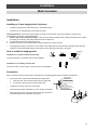
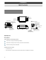
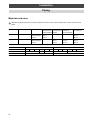
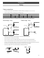
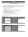
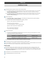
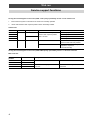
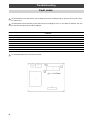
Contents
Contents
Introduction .......................................................................................................................... 4
Installation ............................................................................................................................ 8
Trial run .............................................................................................................................. 36
Troubleshooting ................................................................................................................. 43
Environmental .................................................................................................................... 47
Passer à la page 49 pour lire le manuel d’installation en français.
Die deutsche Installationsanleitung finden Sie auf Seite 95.
Por favor, vaya a la página 141 para seguir las instrucciones del manual de instalacíon en lengua española.
Il manuale d’installazione italiano è a pagina 187.
Zie bladzijde 233 voor de Nederlandse Installatievoorschriften.
See page 279 for the Portuguese Installation Instructions.
See page 325 for the Greek Installation Instructions.
3
Introduction
Contents
Precautions .......................................................................................................................... 5
Operating conditions ............................................................................................................ 6
Metric/Imperial pipe conversion ........................................................................................... 6
Components ......................................................................................................................... 6
4
Introduction
Precautions
Please read these instructions carefully before starting the installation.
This equipment should only be installed by suitably trained operatives.
In all cases ensure safe working practice: Observe precautions for persons in the vicinity of the works.
Ensure that all local, national and international regulations are satisfied.
Check that the electrical specifications of the unit meet the requirements of the site.
Carefully unpack the equipment, check for damage or shortages. Please report any damage immediately.
These units comply with EU Directives:
73/23/EEC (Low Voltage Directive), 89/336/EEC (Electromagnetic Compatibility) and 97/23/EC (Pressure Equipment
Directive). Accordingly, they are designated for use in commercial and industrial environments.
Avoid installation in the following locations:
Where there is danger of flammable gas leakages.
Where there are high concentrations of oil.
Where the atmosphere contains an excess of salt (as in coastal areas). The air conditioner is prone to failure when
used under this condition unless special maintenance is provided.
Where the airflow from the outdoor unit may cause annoyance.
Where the operating noise of the outdoor unit may cause annoyance.
Where the foundation is not strong enough to fully withstand the weight of the outdoor unit.
Where the water drainage may cause a nuisance or a hazard when frozen.
Where strong winds may blow against the air outlet of the outdoor unit.
Precautions for R407C outdoor units
R407C outdoor units use synthetic oils which are extremely hygroscopic. Therefore ensure that the refrigerant system
is NEVER exposed to air or any form of moisture.
Mineral oils are unsuitable for use in these units and may lead to premature system failure.
Use only equipment which is suitable for use with R407C. Never use equipment which has been used with R22.
R407C should only be charged from the service cylinder in the liquid phase. It is advisable to use a gauge manifold set
equipped with a liquid sight glass fitted in the centre (entry) port.
5
Introduction
Operating conditions
OUTDOOR TEMPERATURE
ROOM TEMPERATURE
ROOM HUMIDITY
-5 ~ 43°C
COOLING
-15 ~ 21°C
HEATING
18 ~ 32°C
COOLING
15 ~ 29°C
HEATING
<80%
COOLING
Metric/Imperial pipe conversion
Diameter (mm)
6.4
9.5
12.7
15.9
19.0
22.0
28.6
34.9
41.3
54.1
Nominal diameter (inch)
1/4
3/8
1/2
5/8
3/4
7/8
1-1/8
1-3/8
1-5/8
2-1/8
Note:
1.0 MPa G = 10.2 kgf/cm2 G
Components - 3 pipe system
1.
Outdoor unit
Model name
Inverter unit
MAR-F105HTM8-PE
10 HP
2.
Multi controllers
Model name
No. of indoor units connectable
RBM-Y1034F-PE
3
RBM-Y1044F-PE
4
3.
Interface control kit
Model name
Requirement
RBC-16DIF1-PE
3 or 4 multi controllers used on a system
Combination of multi controllers, indoor units and interface kits
No. of
indoor units
No. of 3-way
multi controllers
1-8
1-2 multi controllers
9
3
0
1
10
2
1
1
11
1
2
1
12
0
3
1
13
3
1
2
14
2
2
2
15
1
3
2
16
0
4
2
6
No. of 4-way
multi controllers
No. of
interface kits
0
Introduction
Components
4.
Indoor units
Type
Appearance
Model name
Capacity code on multi controller
Cassette (4-way)
RAV-164UH-PE
RAV-264UH-PE
RAV-364UH-PE
RAV-464UH-PE
4
6
8
10
Cassette (2-way)
RAV-104TUH-1-PE
RAV-134TUH-1-PE
RAV-164TUH-1-PE
2
3
4
RAV-104SBH-PE
2
RAV-164BH-PE
RAV-264BH-PE
RAV-364BH-PE
RAV-464BH-PE
4
6
8
10
Ceiling Suspended
RAV-134CH/CHR-PE
RAV-164CH/CHR-PE
RAV-264CH/CHR-PE
RAV-364CH/CHR-PE
RAV-464CH/CHR-PE
3
4
6
8
10
High Wall
RAV-105KH-E
RAV-135KH-E
RAV-165KH-E
RAV-265KH-E
2
3
4
6
Built-In Vertical
RAV-104NH-PE
RAV-134NH-PE
RAV-164NH-PE
RAV-264NH-PE
2
3
4
6
Floor Mounted
RAV-164SH/SHR-PE
RAV-264SH/SHR-PE
4
6
Built-In Horizontal
7
Installation
Contents
Outdoor unit
Transportation of the outdoor unit ........................................................................................ 9
Installation of outdoor unit .................................................................................................. 10
Dimensional drawings outdoor unit .................................................................................... 11
Multiple installation on the rooftop ..................................................................................... 12
Multi controller
Installation .......................................................................................................................... 14
Interface kit
Installation .......................................................................................................................... 16
Piping
Connecting refrigerant pipes .............................................................................................. 17
T-piece connections ........................................................................................................... 19
Connection to outdoor unit ................................................................................................. 20
Permissible length and head .............................................................................................. 22
Airtight test ......................................................................................................................... 26
Leak position check/air purge ............................................................................................ 27
Adding the refrigerant/charging the system ....................................................................... 28
Calculating the additional refrigerant required ................................................................... 29
Heat insulation ................................................................................................................... 30
Electrical wiring
General/wiring system overview ........................................................................................ 31
Connecting the power source cable and control cable ...................................................... 32
Wiring between units .......................................................................................................... 33
8
Installation
Outdoor unit
Transportation of the outdoor unit
Fork Lift
•
Front Access – insert the forks into the slots on the fixing legs.
•
Side Access – see diagram.
Front Access
Side Access
Fork lift/hand truck
Fork lift
Fixing leg
Crane
•
Check the suitability of the lifting rope (see table).
•
Secure lifting rope through transportation slot.
•
Protect the unit where rope contact could scratch or deform it.
Protection
Model Number
Weight
MAR-F105HTM8-PE
285 kg
Rope
Protection
Transportation slots
9
Installation
Outdoor unit
Installation of outdoor unit
1.
≥ 20 mm
≥ 20 mm
Align the outdoor units at intervals of 20 mm or more.
Fix the outdoor units with M12 anchor bolts (4 positions
per unit).
20 mm
Anchor bolt with 20 mm length is suitable.
M12 anchor bolt,
4 positions per unit
•
Anchor bolt pitch is as shown in the following figure.
≥ 310 mm
700 mm
≥ 310 mm
700 mm
755 mm
700 mm
15 x 20 mm slot
When routing the refrigerant piping through the base, the fixing height of the base (two-divided foundations) must be
500 mm or more.
≥ 500 mm
2.
Refrigerant piping
3.
Correct foundation mounts for supporting the outdoor unit.
✖✔
10
Installation
Outdoor unit
Dimensional drawings
4-15 x 20 (Slot)
90
Grounding part of bottom plate
Fixing bolt positions
755 790 630
Fixing bolt pitch
90
700
990
Grounding part of bottom plate
Foundation dimensions
750
110 90
1700
1582
700
601
88
Knock outs on
both sides of unit
568
4-60 x 150 slot
(for transport)
500
3-Ø20 cable gland knock outs
Slot pitch
Details of piping connections
Refrigerant pipe connecting port
(Gas suction side) braze connection (Ø28.6)
Refrigerant pipe connecting port
(Liquid side) flare connection (Ø15.9)
315
275
Refrigerant pipe connecting port (gas
discharge side) flare connection (Ø19.0)
68
60
114
All dimensions in mm
11
Installation
Outdoor unit
Multiple installation on the rooftop
If the outer wall is higher than the outdoor unit
≥ 600
≥ 300
If a hole can be made in the wall:
(Front side)
≥ 20
≥ 20
≥ 20
≥ 20
Discharge duct
HD
≥ 10
1.
Vs
≥ 1000
h
H
2.
Set an aperture ratio so that suction air volume Vs
from the hole becomes 1.5 m/s or less
Height of discharge duct: HD = H - h
If a hole cannot be made:
≥ 600
≥ 300
Hole in wall
(Front side)
≥ 20
≥ 20
≥ 20
≥ 20
Discharge duct
HD
≥ 10
Set a base with 500 to 1000 mm height
Height of discharge duct: HD = H - h
h
H
1.
2.
Vs
Note: All dimensions are in mm
Base
500 – 1000
12
Installation
Outdoor unit
If the outer wall is lower than the outdoor unit
≥ 500
≥ 300
1-line installation
(Front side)
≥ 10
≥ 20
≥ 20
≥ 20
≤ 800
≥ 20
≥ 600
* (≥ 1000)
≥ 300
2-parallel lines installation
≥ 300
(Front side)
≥10
≥ 20
≥ 20
≥ 20
≤ 800
≥ 20
≥ 600
* (≥ 1000)
≥ 300
3-parallel lines installation
≥ 500
≥ 600
(Front side)
(Front side)
≥ 10
≥ 20
≥ 20
≥ 20
≤ 800
≥ 20
* When refrigerant piping is routed from the front of the
unit, distance between outdoor unit and piping must be
500 mm or more (for service access).
≥ 500
≥ 500
Note: All dimensions are in mm
Piping
Piping
13
Installation
Multi Controller
Precautions
Avoid installing the multi controller in the following locations:
Where rain water may penetrate the unit.
Where the weight of the unit cannot be supported.
Where it is not level.
Where high temperature under the ceiling or high temperature atmosphere may be produced.
Where there is equipment that generates high frequencies.
Where it is near devices or wiring which may give off electromagnetic interference.
The base of the unit will reach temperatures of approximately 50°C. Do not place heat-sensitive objects close to the
base of the unit.
Installation and service space
Always locate the unit in such a location that the electrical panel can be removed easily. This is very important for trial
tests and service.
Electric
parts box
450 mm x 450 mm
access panel
Handle the multi controller with care.
✔
Do not drop the unit as this could damage components inside.
14
20 mm or more
Indoor
unit connection
side 500 mm
or more
500 mm
or more
Outdoor unit
connection
side 500 mm
or more
Electric parts box
50 mm or more
100 mm
or more
The amount of space that is required for the service area is 450 mm x 450 mm.
Access panel
✖
✖
Installation
Multi Controller
Installation
Installing ø 10 mm hanging bolts (4 pieces)
•
Install the hanging bolts at intervals shown in the following figure.
•
Use the ø 10 mm hanging bolts (to be locally procured).
Ceiling preparation: The actual procedure differs according to the structure. Consult your builder or whoever was
responsible for the interior of the house/building.
1. Remove part of the suspended ceiling: In order to ensure that the ceiling is kept perfectly horizontal and to prevent
the ceiling from vibrating, the ceiling framework must be reinforced.
2. Cut and remove part of the ceiling framework.
3. Reinforce the ends of the ceiling framework where sections have been removed.
•
Some piping and wiring connections must be made in the ceiling after the unit has been suspended. After selecting
where the unit will be installed decide on the direction of the piping and electrical connections.
How to install the hanging bolts
Installation on a newly installed concrete slab:
Use insert brackets or foundation bolts for the installation.
Reinforcing
bar
Knife-shaped
bracket
Sliding bracket
Foundation
bolt
(Foundation bolt for
hanging the piping)
Installation on an existing concrete slab:
Use hole-in anchors, hole-in plugs or hole-in bolts for the installation.
Suspension
Refer to the external view for the position measurement of the hanging bolts and the external measurements.
Hanging bolt
•
Pick up the multi controller after matching with hanging bolts.
1. Hang the notch hole of the back part into the hanging bolt.
2. Fix the slot of the front part onto the hanging bolt.
Nut (up side)
Washer (up side)
Body
•
Tighten the nut firmly, and fix the unit in place.
•
Use a hanging bolt with a diameter of 10 mm (local procurement).
•
After hanging the main unit ensure that it is level then proceed to
make the refrigerant and electrical connections.
Washer (down side)
Nut (down side)
15
Installation
Multi Controller
Model
A
B
C
D
E
F
RBM-Y1034F-PE
460
300
-
90
-
90
RBM-Y1044F-PE
530
370
90
90
90
90
All dimensions are in mm
2 notches for
hanging bolts
(12 x 21)
2 slots for
hanging bolts
(12 x 52)
Electric parts box
80 50
Connection (brazing)
Liquid side ø 15.9
300
A
C D 90 55
E F 90 55
300
3-pipe:
RBM-Y1034F/Y1044F-PE
Refrigerant pipe
connection (brazing)
Liquid side ø 12.7
Wiring knockouts
6 x ø 20
110
Refrigerant pipe
connection (brazing)
Gas side ø 19
Refrigerant pipe
connection (brazing)
Delivery gas side ø 19
Refrigerant pipe
connection (brazing)
Suction gas side ø 28.6
Interface kit
Precautions
Avoid installation in the following locations:
Where there is a danger of flammable gas leakage.
Where there is a danger of water coming in contact with the dual interface.
Where the mounting surface is flammable.
Installation and service space
•
For internal use only.
•
Ensure that there is sufficient space around the dual interface for installation and servicing.
16
Installation
Piping
WARNING!
During installation - if the refrigerant gas leaks, ventilate the room.
After installation - check for gas leakages.
If refrigerant gas comes into contact with fire - noxious gas may result!
Connecting refrigerant pipes
1.
To access the refrigerant piping connections and
electrical wiring terminals, remove the 7 x M5 securing
bolts in the front panel. To remove the panel, lift it up
and away from its hanging tabs - see diagram.
2.
The refrigerant pipes can be routed forwards,
downwards or sideways.
3.
If the pipes are routed forwards, make sure they exit
through the piping/wiring panel - (remove knock out
section) and allow at least 500 mm between the outdoor
unit and the main pipe connecting it to the indoor unit.
This is for servicing access. (Replacing the compressor,
for example, requires a space of at least 500 mm.)
Front panel
≥
If the pipes are routed downwards, remove the knock
out section in the baseplate of the outdoor unit. This will
enable access. They can then be connected to the left
or right, or the rear side.
50
0
Piping/wiring panel
4.
Pipes routed
forward
Pipes routed downwards
Notes:
1. When brazing, use nitrogen. This prevents internal
oxidisation of the pipes.
2.
Always use clean new pipe, and ensure it is not
contaminated by water or dust. Piping material:
seamless, deoxidised copper piping for air conditioning
(refrigeration quality tube).
3.
Always use a double spanner on the flare nut - and
tighten to the specified torque (see table).
Note: All dimensions in mm
Connecting pipe
outer dia. (mm)
Tightening
torque (Nm)
Re-tightening
torque (Nm)
Ø6.4
11.8 (1.2 kgf m)
13.7 (1.4 kgf m)
Ø9.5
24.5 (2.5 kgf m)
29.4 (3.0 kgf m)
Ø12.7
49.0 (5.0 kgf m)
53.9 (5.5 kgf m)
Ø15.9
78.4 (8.0 kgf m)
98.0 (10.0 kgf m)
Ø19.0
98.0 (10.0 kgf m)
117.7 (12.0 kgf m)
Gas discharge
valve position
Liquid pipe
valve position
Gas suction
valve position
17
Installation
Piping
Materials and sizes
Materials and pipes required for connection between the indoor units, multi controllers and outdoor units are shown
below:
Multi controller Outdoor unit
Pipe
Main pipes
Main pipes
outdoor unit to outdoor unit to
multi controller header
Sub pipes
header to
multi controller
Multi controller
connections
1 unit
MAR-F105HTM8-PE Suction gas
Discharge gas
Liquid
Ø28.6
Ø19.1
Ø15.9
-
-
Ø28.6
Ø19.1
Ø15.9
2-4 units
MAR-F105HTM8-PE Suction gas
Discharge gas
Liquid
-
Ø28.6
Ø19.1
Ø15.9
Ø19.1
Ø15.9
Ø12.7
Ø28.6
Ø19.1
Ø15.9
Gas
Indoor unit*
10
Branch pipe sizes
Ø12.7
Multi controller pipe sizes
Ø19.1
Liquid
13
* Example: Indoor unit RAV-264CH-PE = 26
18
16
26
36
Ø15.9 Ø19.1
46
10
Ø6.4
Ø12.7
13
16
26
Ø9.5
36
46
Installation
Piping
T-piece connections
•
The main T-piece should be equal dimensions in all three positions, for example 12.7 x 12.7 x 12.7 mm.
•
The sub T-pieces should be a reducing type, see diagram below.
Outdoor unit
Suction
gas
MAR-F105HTM8-PE
Discharge
gas
Liquid
ØA
ØB
ØA
ØB
ØA
ØB
28.6
19.1
19.1
15.9
15.9
12.7
Note: There must be at least 500 mm of straight pipe before any T-piece, this is to ensure equal distribution.
Header design - 3-way
Header design - 4-way
ØB
ØB
500 mm
ØA
ØA
Equal T-piece
Equal T-piece
ØB
ØB
ØA
Reducing
T-piece
ØA
Reducing
T-pieces
ØB
ØA
ØA
ØB
Reducer
ØB
500 mm
500 mm
500 mm
•
Keep the T-piece horizontal to the multi controller, if necessary bending the sub piping.
•
Secure the T-piece to a wall or joist in the ceiling.
•
Ensure a minimum of 500 mm of straight piping before any T-piece. This is to ensure equal distribution.
•
Ensure correct pipe dimensions are used, between outdoor unit, T-pieces, multi controller and indoor units.
•
As shown in the above tables, ensure the size of the main gas pipe between the T-piece and the outdoor unit must be
the next size up compared with the pipe size between the T-piece and the multi controllers.
•
Ensure any unused circuits on the multi controllers are sealed with brazed cap.
Horizontal
✔
✖
Horizontal
Inclined
✔
Inclined
✖
Main pipe
from the
outdoor unit
Sub pipes
to the multi
controllers
500 mm
or more
19
Installation
Piping
Connection to outdoor unit
•
•
•
•
•
The refrigerant pipes are connected inside the outdoor unit.
The pipes can be routed forwards, downward or sideways.
Do not use a liquid sight glass or incorporate an oil trap in vertical pipework.
A dryer is incorporated into the piping of the outdoor unit.
Cleanliness is essential - keep the piping securely sealed at all times throughout the installation.
Suction gas valve brazing
Liquid pipe
valve position
Gas discharge
valve position
Gas suction valve position
When brazing, position a wet cloth around
the suction valve to ensure the temperature
remains below 120°C otherwise equipment
damage may result.
Pipework routed forwards
•
•
•
If pipework is routed forwards ensure they exit through the piping and wiring panel (remove knock out section first)
Cut the connecting section at the end of the pipe with a pipe cutter.
Allow at least 500 mm between the outdoor unit and the main pipe connecting it to the indoor unit. This is for servicing
access. (Replacing the compressor, for example, requires a space of at least 500 mm.)
Suction valve
Shaped pipe section
Cut connecting end section
20
Installation
Piping
Pipework routed downwards
•
•
•
•
If the pipes are routed downwards, remove the knock out section in the baseplate of the outdoor unit. This will enable
access. They can then be connected to the left or right, or the rear side.
De-braze or cut with a pipe cutter the connecting section above the flare.
Braze connecting pipework to suction valve pipe.
Ensure the suction valve is kept cool at all times.
Suction valve
Cut or debraze L-shaped pipe
Braze connecting pipe
Remove base plate knock out
Pipework routed sideways
•
•
•
•
If the pipes are routed sideways, remove the knock out section in the sideplate of the outdoor unit. This will enable
access.
De-braze or cut with a pipe cutter the connecting section above the flare.
Braze connecting pipework to suction valve pipe.
Ensure the suction valve is kept cool at all times.
Suction valve
Cut or debraze
L-shaped pipe
Braze connecting pipe
Indoor unit
pipework
Connecting refrigeration pipes
(outdoor/multi controller/indoor)
•
When brazing, position a wet cloth around
the pipework between the brazed joint and
multi controller to ensure the temperature
remains below 120°C. Equipment damage
to components within the multi controller
may result if not protected.
Indoor units
Wet cloth position
Braze
positions
Multi controller
Outdoor unit
Gas suction side
Gas discharge side
Liquid side
21
Installation
Piping
Permissible piping length and head
The maximum piping length from
L ≤ 120 m
Equivalent length
the outdoor unit to the indoor unit
Actual length
L ≤ 100 m
The maximum height difference from the outdoor unit to
When the outdoor unit is above
H ≤ 50 m
the multi controller or the indoor unit
When the outdoor unit is below
H ≤ 20 m
One-Multi-Controller system
Branch pipe
Main pipe
Indoor A
Indoor B
Multi controller 1
Indoor C
Indoor D
Outdoor unit
Maximum piping lengths (actual)
No. of
multi controllers
Main pipe
Branch pipe
Max. total pipe
1
3 m - 70 m
2 m - 30 m
100 m
Permissible piping length
H1
Maximum height difference between
multi controller and indoor unit
≤ 15 m
H2
Maximum height difference between
indoor units
≤ 15 m
∆L
Maximum piping difference between
multi controller and indoor unit
≤ 10 m
∆L = longest pipe (L2) - shortest pipe (L1)
Pipe size
22
Gas suction pipe
ØA
Liquid pipe
ØA
Gas discharge pipe
ØA
28.6
15.9
19.1
Installation
Piping
Two-Multi-Controller system
Main pipe
Branch pipe
Sub pipe
Indoor A
Multi controller 1
Indoor B
Indoor C
Indoor D
Reducing
T-piece
Indoor E
Outdoor unit
Indoor F
Multi controller 2
Indoor G
Sub pipe
Indoor H
Maximum piping lengths (actual)
No. of
multi controllers
2
Main pipe
Sub pipe
Branch pipe
Max. total pipe
2 m - 70 m
1 m - 15 m
2 m - 30 m
100 m
Main pipe + longest sub pipe ≤ 70 m
Permissible piping length
H1
Maximum height difference between
multi controller and indoor unit
≤ 15 m
H2
Maximum height difference between
indoor units
≤ 15 m
∆L
Maximum piping difference between
multi controller and indoor unit
≤ 10 m
∆K
Maximum piping difference between
sub pipes (K2 - K1)
≤ 10 m
L = longest pipe - shortest pipe
Pipe size
Gas suction pipe
ØA
Liquid pipe
ØA
Gas discharge pipe
ØA
28.6
15.9
19.1
19.1
12.7
15.9
23
Installation
Piping
Three-Multi-Controller system
Main pipe (X)
Main pipe (Y)
Branch pipe
Sub pipe
Indoor A
Indoor B
Multi
controller 1
Reducer
Indoor C
Indoor D
T-piece
Indoor E
Sub pipe
Outdoor unit
Indoor F
Multi
controller 2
Indoor G
Indoor H
Reducing
T-piece
Indoor I
Indoor J
Multi
controller 3
Main pipe (Z)
Indoor K
Indoor L
Maximum piping lengths (actual)
No. of
multi controllers
Main pipe (X+Y+Z) Sub pipe
Branch pipe
Max. total pipe
3
2 m - 70 m
2 m - 30 m
100 m
1 m - 15 m
Main pipe + longest sub pipe ≤ 70 m
Permissible piping length
Pipe size
H1
Maximum height difference between
multi controller and indoor unit
≤ 15 m
H2
Maximum height difference between
indoor units
≤ 15 m
∆L
Maximum piping difference between
multi controller and indoor unit (L2 - L1)
≤ 10 m
∆K
Maximum piping difference between
sub pipes (K2 - K1)
≤ 10 m
∆M
Maximum piping difference between
main pipes Y and Z (M2 - M1)
≤ 10 m
L = longest pipe - shortest pipe
24
Gas suction pipe
ØA
Liquid pipe
ØA
Gas discharge pipe
ØA
28.6
15.9
19.1
19.1
12.7
15.9
Installation
Piping
Four-Multi-Controller system
Branch pipe
Main pipe (Y) Sub pipe
Main pipe (X)
Indoor A
Multi
controller 1
Indoor B
Indoor C
Indoor D
Indoor E
Multi
controller 2
Indoor F
Indoor G
Indoor H
T-piece
Indoor I
Outdoor unit
Indoor J
Multi
controller 3
Indoor K
Indoor L
Reducing
T-piece
Indoor M
Multi
controller 4
Main pipe (Z)
Indoor N
Indoor O
Indoor P
Maximum piping lengths (actual)
No. of
multi controllers
4
Main pipe (X+Y+Z) Sub pipe
Branch pipe
Max. total pipe
2 m - 70 m
2 m - 30 m
100 m
1 m - 15 m
Main pipe + longest sub pipe ≤ 70 m
Pipe size
Permissible piping length
H1
Maximum height difference between
multi controller and indoor unit
≤ 15 m
H2
Maximum height difference between
indoor units
≤ 15 m
∆L
Maximum piping difference between
multi controller and indoor unit (L2 - L1)
≤ 10 m
∆K
Maximum piping difference between
sub pipes (K2 - K1)
≤ 10 m
∆M
Maximum piping difference between
main pipes Y and Z (M2 - M1)
≤ 10 m
Gas suction pipe
ØA
Liquid pipe
ØA
Gas discharge pipe
ØA
28.6
15.9
19.1
19.1
12.7
15.9
L = longest pipe - shortest pipe
25
Installation
Piping
Airtight test
Carry out an airtight test after the refrigerant piping is complete. For an airtight test, connect a nitrogen gas bottle as
shown, and apply pressure (use oxygen-free nitrogen, OFN).
The pressure test must be completed before supplying power to ensure that the multi controller PMVs (pulse
modulating valves) are open.
The test must be completed with the indoor units, multi controllers and outdoor unit connected.
•
•
•
Be sure to carry out the test from the service ports of the packed valves at the discharge gas, liquid and suction
gas side.
Keep all of the valves at discharge gas, liquid and suction gas sides fully closed. Nitrogen may enter the cycle of
the outdoor unit. Therefore, retighten the valve rod before applying pressure. (For all valves.)
For each refrigerant line, apply pressure gradually at the discharge gas, liquid and suction gas sides.
Never use oxygen, or a flammable noxious gas.
Low
High
pressure pressure
gauge
gauge
Packed valve fully closed
(gas suction side)
Detailed drawing of packed valve
Gauge
manifold
Inverter outdoor unit
Brazed
Service port at gas
discharge side
To
manifold
Service port
Flare
connection
Copper
pipe
ø 6.4
Service port
Service port at
gas suction side
Flare
connection
Packed valve fully
closed (liquid side)
Regulator
Copper
pipe
ø 6.4
Nitrogen gas
Service port at
liquid side
Packed valve fully closed
(gas discharge side)
To detect a large leakage
Step 1: 0.3 MPa (3 kg/cm2 G) Apply pressure for 3 minutes or more
Step 2: 1.5 MPa (15 kg/cm2 G) Apply pressure for 3 minutes or more
To detect a fine leakage
Step 3: 3.0 MPa (30 kg/cm2 G) Apply pressure for 24 hours
•
Check for a reduction in pressure.
If there is no reduction in pressure this is acceptable.
If there is a reduction in pressure check for a leakage.
(Note: If there is a difference of ambient temp. between when the pressure was applied and 24 hours later, then pressure
could change by approx. 0.01 MPa (0.1 kg/cm2 G) - so correct the pressure change.
26
Installation
Piping
Leak position check
If a pressure drop is detected, check for leakage at connecting points. Locate the leakage by listening, feeling, using
foaming agent, etc. - then rebraze or retighten.
Air purge
The air purge must be completed before supplying power to ensure the multi controller’s PMVs are open.
Using a vacuum pump, complete an air purge. Never use refrigerant gas.
•
After the airtight test, discharge the nitrogen gas.
•
Connect a gauge manifold to the service port at discharge gas, liquid and suction gas sides, and connect a vacuum
pump as shown.
•
Be sure to vacuum at discharge gas, liquid and suction gas sides.
Detailed drawing of packed valve
Packed valve fully closed
(gas suction side)
Inverter outdoor unit
Low
High
pressure pressure
gauge
gauge
Gauge
manifold
Brazed
Service port at gas
discharge side
To
manifold
Service port
Flare
connection
Service port
Service port at
gas suction side
Flare
connection
Service port at
liquid side
Packed valve fully
closed (liquid side)
Vacuum pump
Packed valve fully closed
(gas discharge side)
•
Use a vacuum pump with high vacuum carry-over degree (-0.013 x 10⁵ Pa; 0.750 mm Hg or less) and large
displacement (40 l/min. or more).
•
Ensure to create a vacuum at -0.013 x 10⁵ Pa (0.75 mm Hg) at the discharge gas, liquid and suction gas.
•
After the procedure has been completed, replace the vacuum pump with a refrigerant bottle and add the refrigerant if
required.
27
Installation
Piping
Adding the refrigerant
After the airtight test, replace the vacuum pump with a refrigerant bottle to charge the system.
Calculating the additional refrigerant required
The refrigerant amount at shipment does not include the refrigerant needed for the piping - so first calculate this amount,
and then add it.
Refrigerant charge amount shipped from the factory
Outdoor unit model name
MAR-F105HTM8-PE
Charging amount (kg)
19.0
Maximum gas charge (kg)
36.3
The amount of additional refrigerant is calculated from the actual length of the liquid pipe.
To calculate the additional refrigerant volume, refer to the diagram and follow the steps below:
(i)
The main pipe length is taken as the addition of pipes X, Y and Z.
(ii)
The sub pipe length is taken as the addition of the two longest of the four (if 4 multi controllers).
(iii) The branch pipe lengths must be individually calculated using the 8 longest pipes.
(iv) Do not attempt to add gas above the maximum shown in the table above.
(v)
For systems with one multi controller ignore the sub-pipe section within the additional gas charge calculation.
(vi) When using three multi controllers, it is important that a reducer is used on the pipework for the third multi controller.
Pipework before the reducer is classed as main piping and after as sub piping.
Charging the system
•
Keeping the outdoor unit valve closed, charge the refrigerant from the service port on the liquid side.
•
If the specified amount of refrigerant cannot be charged - fully open all the outdoor unit’s valves, then perform the
cooling operation with the valve at the gas side slightly closed.
•
If leaks cause a shortage of refrigerant - recover the refrigerant from the system, and recharge with new refrigerant to
the total refrigerant charge.
28
Installation
Piping
Additional refrigerant
One Multi Controller
Indoor
Outdoor
M/C
L3
L1
Two Multi Controllers
Indoor
Outdoor
M/C
Table 1 - Branch pipes
L2
L1
L3
RAV-10* : 0.030 kg/m
RAV-13* : 0.030 kg/m
RAV-16* : 0.030 kg/m
Three Multi Controllers
RAV-26* : 0.045 kg/m
Indoor
RAV-46* : 0.045 kg/m
M/C
Outdoor
Example:
RAV-464CH-PE RAV-46*
Y
X
RAV-36* : 0.045 kg/m
L3
L2
Z
Four Multi Controllers
Indoor
M/C
Outdoor
Y
X
Z
L2
L1 = Main pipe (X + Y + Z)
L2 = Sub pipe
L3 = Branch pipe
L3
Pipe
MAR-F105 - main pipe L1 (X+Y+Z) (minus 2 m)
1st longest sub pipe L2 (minus 1 m)
2nd longest sub pipe L2 (minus 1 m)
1st longest branch pipe L3 (minus 2 m)
2nd longest branch pipe L3 (minus 2 m)
3rd longest branch pipe L3 (minus 2 m)
4th longest branch pipe L3 (minus 2 m)
5th longest branch pipe L3 (minus 2 m)
6th longest branch pipe L3 (minus 2 m)
7th longest branch pipe L3 (minus 2 m)
8th longest branch pipe L3 (minus 2 m)
x
x
x
x
x
x
x
x
x
x
x
Additional gas/metre
Additional gas
0.19 kg/m
=
0.125 kg/m
=
0.125 kg/m
=
Refer to Table 1
=
Refer to Table 1
=
Refer to Table 1
=
Refer to Table 1
=
Refer to Table 1
=
Refer to Table 1
=
Refer to Table 1
=
Refer to Table 1
=
Total additional gas charge
=
kg
29
Installation
Piping
Heat insulation
•
Provide heat insulation on the refrigerant piping on both the liquid side and the gas side separately, and ensure that
joints in the insulation are vapour-sealed.
•
Since the temperature of the piping on the gas side increases during heating operations, the heat insulating material
used must be able to withstand temperatures of more than 120°C.
Liquid pipe
Gas pipe
✖
Thermal insulator
Thermal insulator
Gas pipe
•
Thermal insulator
Liquid pipe
✔
Insulate the pipework as shown in the diagram below, slide insulation up to the insulation on the multi controller and
seal joint with heat insulating tape.
Heat insulating tape
Pipe insulation butted together
Brazed joint
•
30
In the situation where high ceiling ambient temperatures are present thicker pipe insulation should be used.
Installation
Electrical wiring
Precautions
This guide should be read and utilised in conjunction with official published regulations and codes of practice, be they
local, national or international.
Each air conditioning system will have its own discrete power supply, with overload current protection. The electrical
power will be supplied to the outdoor unit via the built-in isolator.
The indoor units will derive their electrical power from the multi controller, and they in turn will derive their power from
the outdoor unit.
The interface kit will derive its electrical power from the outdoor unit.
The circuit protection device will protect the supply cable against overcurrent. The circuit protection must be selected
having due regard to the compressor starting current, such that the supply cables when sized correctly, are protected.
The cable should be selected to match the nominal load of the system, in addition to the losses associated with
corrections for length, temperature, impedance, etc. In accordance with local codes of practice.
Please refer to the unit’s nameplate and the relevant technical specifications to determine the correct power supply.
Distribution board
Power supply wiring
•
Connect the power supply cables to the isolator on the outdoor unit.
•
Secure the power cables on the terminal contact firmly.
Built-in isolator
Super Multi
outdoor unit
•
Do not allow the cables to come into contact with any valves or pipes.
•
Use the correct sized cable glands when connecting the power supply cables to the service panel.
•
The table below shows the supply requirements.
Model
Running
current (A)
Starting
current (A)
Power
supply
MAR-F105HTM8-PE
17.7
60
3 Ø 50 Hz
380/415 V
31
Installation
Electrical wiring
Connecting the power source cable and control cable
Insert the power source cable and control cable after removing the knockout in the piping / wiring panel on the front or side
of the outdoor unit.
Knock out (x4) for control cable
and power source cables
Piping/wiring panel
Power source cable
•
•
Connect the electric cables and earth wire to the outdoor isolator terminal block through a notched section at side of
the electric parts box, and fix with a clamp.
Bundle the electric cables using the hole so that they are in the notched section of the electric parts box.
Control cable
•
Connect the control cable between indoor and multi controller units through a hole at the side of the electric parts box,
and fix with a clamp.
Notes:
1
Be sure to separate the power source cables
and each control cable.
2
Arrange the power source cables and each
control cable so they are not in contact with
the bottom surface of the main unit.
Electrical parts box
Power supply
connections
Isolator
Earth screw
Multi controller terminal block (for
wiring control cable between
outdoor and multi controller units)
Earth screw (shielded wire)
32
Installation
Electrical wiring
Wiring between units
•
Connect the wires between the units correctly. Errors made in the connections can result in the unit malfunctioning.
Multi controller A
Indoor unit
Outdoor unit
Indoor unit
Multi
controller A
DIF 1
Multi
controller B
Multi
controller C
Outdoor unit
DIF 2
Multi
controller D
L
The length of the wires between the outdoor and multi controller units must be 80 metres or less.
l
The length of the wires between the indoor and multi controller units must be 80 metres or less.
For one and two multi controllers
•
Connect the control wires between the outdoor unit, indoor units and the multi controller as shown in the figure below:
Multi controller #2
Multi controller #1
Outdoor unit
connections
Indoor unit connections
A1 A2 A3
B 1 B2 B 3
C 1 C2 C3
1 2 3
1 2 3
1 2 3
Indoor unit A
Indoor unit B
Indoor unit C
Outdoor unit
connections
1 2 3
1 2 3
1 2 3
M/C (1)
1 2 3
M/C (2)
Outdoor unit
33
Installation
Electrical wiring
For three and four multi controllers
•
Connect the control wires between the multi controllers and indoor units as shown in the figure below:
Multi controller #1
Indoor unit connections
A1A2 A3
Indoor unit A
Outdoor unit
connections
B1B2 B3
C1 C2 C3
Indoor unit B
Indoor unit C
M/C (1)
DIF 1
•
Connect the control wires between the multi controllers and outdoor unit as shown in the figure below:
Multi controller #1
M/C (1)
Multi controller #2
Multi controller #3
M/C (2)
M/C (1)
O/D
M/C (2)
O/D
Dual interface 2
Dual interface 1
M/C (2)
M/C (1)
Outdoor unit
34
Multi controller #4
Installation
Electrical wiring
Setting of indoor unit capacity codes
•
The setting of the indoor unit capacities is important. Set the correct indoor unit code numbers according to the indoor
unit capacity. The capacities are set by the rotary switches on the printed circuit board switch A (unit A), switch B (unit
B), switch C (unit C) and switch D (unit D).
•
During manufacture, the indoor capacity selection switches are set at ‘0’.
•
Record the indoor capacity codes, indoor unit model names and locations in the table following, and on the wiring
diagram on the electrical panel cover.
Example:
Room A
Room B
Capacity 16
Indoor unit
Room C
Capacity 16
Capacity 26
Capacity
No connection
10
13
16
20
26
36
46
Code number
0
2
3
4
5
6
8
10
(Example: Model RAV-364UH-PE, capacity = 36)
Multi controller PCB
MCC-1210
Capacity select switches
•
Multiple indoor units may be connected to each outdoor unit, providing the total indoor code does not exceed the limits
shown below.
Combination of multi controllers and indoor units
Number of
multi controllers
Maximum No. of
indoor units
Indoor unit diversity
Maximum system code
Maximum code per
multi controller
1
4
135%
27
27
2
8
160%
32
27
3
12
27 (13*)
4
16
13
Example of systems with maximum possible code:
Outdoor unit
OD
OD
OD
OD
OD
OD
Interface kit
Multi controller [code]
(Max. system code)
OD
OD
DIF
DIF
DIF
27
27
(27)
6
27
26
27
(32)
6
13
6
13
(32)
20
27
8
13
DIF
DIF
8
13
8
13
8
13
(32)
35
Installation
Electrical wiring
Precautions
At factory shipment the indoor capacity selection switch, on the multi controller, is set at ‘0’. If the switch remains at the
‘0’ setting, the relevant indoor unit will not operate.
When power is supplied indoor capacity code data cannot be rewritten, even if the code setting switch is changed. Set
the capacity code before supplying power. To change the capacity codes once the power has been applied, set the
desired codes using the appropriate switches and push the reset button on the multi controller for 2 or 3 seconds; this
will reset the PCB.
RBM-Y1034F-PE switch D is to be set at ‘0’.
If the capacity code number is not set correctly, the desired cooling or heating capacity will not be obtained. This could
cause the system to malfunction. If the total of the capacity codes exceeds 32 (10HP outdoor unit), the air conditioner
will not function.
Trial run
Precautions
The power must be applied to the unit for at least 12 hours before operating the unit. This is to ensure the compressor
is fully warmed by the heater otherwise the unit may malfunction.
Do not under any circumstances force the unit to operate by using the magnetic contactor override.
Before conducting the trial run, be sure to remove all packaging from the unit.
Ensure that the correct capacity code for each of the indoor units is set correctly on the multi controller’s PCB.
The total of the capacity codes must not exceed 27 (1 multi controller) or 32 (2-4 multi controller).
Check the refrigerant piping and control wires are connected correctly to the multi controller, i.e. the control wiring and
refrigerant piping of unit A matches the unit A’s connections on the multi controller.
Procedure
•
•
Conduct the trial run as follows, ensuring to act on the instructions of the following checklists.
Write the results onto the checklists. These will be very helpful documents for service and maintenance in the future.
Initial check
Trial run
Problem solving
Trial complete
•
•
•
•
36
Check the basic installation work by filling out checklist #1.
Use checklist #2 to conduct the trial run test, record the results.
If problems occur, correct them and rerun the test.
If problems still persist, refer to the service manual for full details.
Trial run
Checklist # 1
Is the installation work finished correctly?
Indoor unit
model name
1)
Is the capacity number switched
M/C
Unit A
on the multi controller PCB
(1)
Unit B
registered correctly to each
Unit C
indoor unit?
Unit D
M/C
Unit A
(2)
Unit B
Registered
code number
Check result
Unit C
Unit D
M/C
Unit A
(3)
Unit B
Unit C
Unit D
M/C
Unit A
(4)
Unit B
Unit C
Unit D
2)
Are there any wrong connections of the refrigerant piping control wiring between indoor
units and multi controller?
3)
Are there any wrong connections of both control wiring between indoor unit and multi
controller, and multi controller and outdoor unit?
4)
Is the circuit breaker installed?
5)
Is the breaker capacity adequate?
6)
Breaker capacity
A
Is there any wrong wiring of power cable?
Power cable
mm2
7)
Is the wire size correct?
Control wire
mm2
8)
Is the wiring correct between distribution board and outdoor unit?
9)
Is the grounding attached?
10) Is there adequate resistance? (More than 10 MΩ) Insulation resistance
MΩ
11) Is the voltage correct?
V
Voltage
12) Is the condensate draining adequate?
13) Is the heat insulation sufficient for all pipework?
14) Is there a short-circuit of air flow from the indoor unit?
15) Is there a short-circuit of air flow from the outdoor unit?
16) Is there sufficient refrigerant?
17) Are the valves fully opened?
18) Does the remote controller operate properly?
37
Trial run
Checklist # 2
Trial run
•
After the initial check has been completed, the trial run may commence.
•
The trial run should be completed individually for each and every indoor unit. If multiple units are operating
simultaneously, you cannot carry out the check for cross connection between refrigerant piping and control wiring.
•
For each indoor unit confirm both cooling and heating operations.
•
Work through the checklist #2 below, filling in the relevant data, as the test proceeds.
Checklist #2
No.
Operation procedure
Check items
Confirmation
M/C (1)
M/C (2)
M/C (3)
M/C (4)
Unit Unit Unit Unit Unit Unit Unit Unit Unit Unit Unit Unit Unit Unit Unit Unit
A
B
C
D
A
B
C
D
A
B
C
D
A
B
C
D
1
Turn on the power
Is the LED on the remote
controller flashing?
2
(Check the fan operation)
Is the air flow blowing out from
Set the operation mode to
the air outlet?
‘Fan’, and start operation.
Is there abnormal noise from the
fan?
3
(Check the cooling operation) Does the compressor start
Set the operation mode to
normally?
‘Cooling’ and start operation. Is there abnormal sound?
(Once you have stopped
(compressor, piping)
operation, you have to wait
Is the cool air flow coming out?
for 3 minutes to restart due
Is the air flow circulating
to the built-in restart delay
adequately?
circuit functioning)
Does the thermostat work
normally?
(Confirm that compressor stops
at high temperature setting, and
restarts at low temperature setting)
In this case, check
Is the temperature difference
every indoor unit’s
correct between return air and
operation
outlet air?
simultaneously.
Is the power supply voltage
Set the
correct? (220-240 V)
temperature to the
Is the operating current correct?
lowest level
Is the operating pressure correct?
4
(Check the heating operation) Does the compressor start
(note)Set the operation mode to
normally?
‘Heating’ and start the
Is there abnormal sound?
operation
(compressor, piping)
(Once you have stopped
Is the warm air flow coming out?
operation, you have to wait
Is the air flow circulating
for 3 minutes to restart due
adequately?
to the built-in restart delay
Does the thermostat work normally?
circuit functioning)
(Confirm that compressor stops
at low temperature setting, and
restarts at high temperature setting)
In this case, check
Is the temperature difference
every indoor unit’s
correct between return air and
operation
outlet air?
simultaneously.
Is the power supply voltage
Set the
correct? (220-240 V)
temperature to the
Is the operating current correct?
highest level
Is the operating pressure correct?
(Note) When the outdoor temperature rises above 25°C, heating operation will cease.
38
Trial run
Circuit test procedure
•
These systems have a feature which enables them to check that the wiring and piping connections are aligned with
each other. This is carried out by allowing refrigerant to flow to one indoor unit at a time and monitoring that indoor
unit’s coil sensor for a corresponding drop in temperature. Each indoor unit is tested in turn and where two multi
controllers are installed each multi controller is tested in turn.
•
This test would normally be used at the commissioning stage.
•
Procedure for initialising the circuit test.
1. Turn the power off.
2. Ensure the capacity codes are set correctly, capacity switches set to ‘0’ are not tested.
3. Put the outdoor display switches SW1 and SW2 to 9 and multi controller(s) display switch to 6.
4. Turn the power back on.
5. Set all the remote controllers to cool mode and 29°C.
6. Press the on/off button to start all the indoor units (the outdoor LEDs show ‘1020’).
7. Press the outdoor unit switch SW3, and hold for 3 seconds.
8. The system is now in self-testing (all 8 LEDs will be flashing rapidly).
9. The system will stop at the end of the test.
•
In the event of cross wiring/piping the system will indicate which units are faulty, see table below:
Outdoor display switch SW1 and SW2 set to position 9.
One and two Multi Controllers
Display
Multi controller
Fault
1020
All
None
1A20
1
Unit A
1B20
Unit B
Units that are indicated
1C20
Unit C
failed the test
1D20
102A
Unit D
2
Unit A
102B
Unit B
102C
Unit C
102D
Unit D
Three or more Multi Controllers
Display
Multi controller
Fault
1020
All
None
1A20
1
Unit A or B
1B20
1C20
2
1D20
102A
102D
Units that are indicated
Unit A or B
failed the test
Unit C or D
3
Unit A or B
4
Unit A or B
102B
102C
Unit C or D
Unit C or D
Unit C or D
39
Trial run
Additional notes
Temperature difference between the indoor unit’s air inlet and outlet.
(i)
(ii)
If the difference between the dry bulb temperatures at the indoor unit’s air inlet and outlet is 10 K or more when
the unit has been operating for at least 30 minutes in ‘cooling’ mode, the system is operating correctly (at
maximum compressor frequency).
If the difference between the dry bulb temperatures at the indoor unit’s air inlet and outlet is 18 K or more when
the unit has been operating for at least 30 minutes in ‘heating’ mode, the system is operating correctly (at
maximum compressor frequency).
Current measurement
(i)
(ii)
If the current is within ± 15% of the value given, in both heating and cooling modes, the system is operating
correctly (at maximum compressor frequency).
The current varies as follows, depending on the operating conditions
When the current is higher than the standard current:
High indoor/outdoor temperatures
Poor heat dissipation of outdoor unit (during cooling)
When the current is lower than the standard current:
Low indoor/outdoor temperatures
Gas leak (insufficient refrigerant)
Pressure measurement
(i)
(ii)
The pressure levels established 15 minutes after start-up are shown below (dry bulb temperatures °C, with the
unit operating at maximum compressor frequency)
Cooling
High pressure: 16 - 20 kg/cm2 or 1.57 - 1.96 MPa
Low pressure: 3.5 - 5.5 kg/cm2 or 0.34 - 0.54 MPa
Indoor 18 to 32°C
Outdoor 25 to 35°C
Heating
High pressure: 15 - 21 kg/cm2 or 1.47 - 2.06 MPa
Low pressure: 3.0 - 4.5 kg/cm2 or 0.29 - 0.44 MPa
Indoor 15 to 25°C
Outdoor 5 to 10°C
The operating conditions of the system will effect the pressures in the system.
The flashing of the remote controller’s operation lamp does not indicate a failure.
If the total capacity code allowable is exceeded, the ‘preheat/defrost’ will flash, at 4 second intervals, on the LCD of the
remote controller. This does not indicate a failure, however it should be corrected.
Fault codes
The remote controller, multi controller and outdoor units are provided with a means of checking the status of the
system. This is achieved by the use of a ’check’ display on the remote controller, and an LED display located on the
microcomputer control PCB which itself is located in the outdoor unit’s electrical box. The multi controller fault codes
are repeated at the outdoor unit.
Any faults that occur can be identified by the use of these fault codes.
For full details please refer to the service manual
40
Trial run
Phase rotation test procedure
•
The dual-scroll compressor is unidirectional, whilst the variable speed inverter compressor’s direction of rotation is
determined internally, the fixed-speed is not, and is dependant upon the correct input electrical phase sequence.
•
Start the system in either cool or heat mode, depending on the building requirements. Allow the machine to assume
full-load. The inverter compressor will start and, at its maximum speed, will commence to slow its speed prior to the
fixed-speed compressor being energised.
•
If the phase rotation is correct, the main contactor will energise and allow the second fixed-speed compressor to run. If
this is the case then proceed to the next test.
•
If the phases are not correctly aligned, the second compressor will not start and the inverter will stop. Allow the inverter
compressor to restart itself after the recycle period has elapsed; it will repeat the above sequence. At the end of this
sequence, allow two minutes before interrogating the remote controller, multi controller or the outdoor interface PCB
for a fault code.
•
Display check for incorrect phase alignment.
Unit number
Remote controller
CHECK
CHECK
UNIT
__ __
09._ _
Fault code
•
If the phase rotation is incorrect, interchange the incoming supply cables to L2 and L3 and reset the system.
41
Trial run
Service support functions
Forcing the electromagnetic control valve (PMV 1 and 2) fully opened/fully closed - on the outdoor unit
1.
Ensure that the system is OFF before the valves are manually operated.
2.
Valves will reassume their required position unless electrically isolated.
Outdoor unit
SW1
SW2
Short point
Operation
Function
0
N/A
TP1
Valves will automatically
PMV 1 fully open for 2 minutes
assume their required position
PMV 2 fully open for 2 minutes
after 2 minutes
PMV 1 fully closed for 2 minutes
1
0
TP2
1
2
PMV 2 fully closed for 2 minutes
0
TP3
Press SW04
Solenoid valves manually energise in
sequence when switch is pressed
Press SW03
Solenoid valves automatically
energised in sequence
(1 second intervals)
Forcing the electromagnetic control valve (PMV A/B/C/D) fully opened/fully closed - on the multi controller
Multi controller
Display switch
position
Valve
Short point
0
PMV A
TP1
1
PMV B
2
PMV C
Selected valve is fully open for
Selected valve is fully closed for
3
PMV D
2 minutes
2 minutes
42
TP2
Troubleshooting
Self-diagnostic function
Remote controller fault code
No communication signal between Interface PCB and IPDU
04 No communication signal between M/C and O/D
Multi controller fault code
04 No communication signal between Interface PCB and IPDU
No communication signal between M/C and O/D.
Outdoor fault code
No communication signal between Interface PCB and IPDU
No communication signal between I/D and M/C
0b Drain pump fault - I/D unit
0C TA sensor fault
0d TC sensor fault
08 Reverse TC temperature change
09 No TC temperature change
11 Motor short circuit
8A Multi Controller PCB error
b5 External input display fault
88 Communication error between indoor unit and Multi
Controller
(Low level refrigerant leak if RBC-RD1-PE fitted)
b6 External interlock display fault
(High level refrigerant leak if RBC-RD1-PE fitted)
80 ThA sensor fault
81
ThB sensor fault
97 Central management communication short circuit
82 ThC sensor fault
98 Central management address set-up fault
83 ThD sensor fault
99 No communication I/D to R/C
84 ThX sensor fault
0b Drain pump fault - M/C unit
15 Refer to M/C
1C Refer to O/D
89 Indoor units capacity codes too high or set to 0
1C
Refer to O/D
12 Indoor PC board short circuit
80 ThA sensor fault
81 ThB sensor fault
82 ThC sensor fault
83 ThD sensor fault
84 ThX sensor fault
0b Drain pump fault - M/C unit
89 Over capacity
Er
[E][r] fault code refers to Outdoor unit
08 Four-way valve alarm.
A0 Discharge temp. sensor (TD1) short circuit
A1 Discharge temp. sensor (TD2) short circuit
A2 Suction temp. sensor (TS) short circuit
A4 External air sensor (THo) short circuit
A5 Outdoor heat exchanger sensor (TE) short circuit
A6 Discharge temp. (TD1) protective operation
A7 Suction temp. (TS) protective operation
AA High pressure sensor (Pd) short circuit
Ad DOL compressor fault
AE Low pressure fault (Ps)
AF Outdoor Unit power source phase order miswiring
14 Refer to O/D
17 Refer to O/D
21 Refer to O/D
1d Refer to O/D
1F Refer to O/D
d3 Refer to O/D
dA Refer to O/D
14
17
21
1d
1F
d3
dA
1C Extension IC, EEPROM short circuit
Refer to O/D
Refer to O/D
Refer to O/D
Refer to O/D
Refer to O/D
Refer to O/D
Refer to O/D
14
17
21
1d
1F
d3
dA
G-Tr short-circuit protective operation
Current detection circuit
High pressure SW circuit
Compressor error
Inverter malfunction
TH sensor circuit - Inverter microprocessor (IPDU)
Heat sink overheat protective operation (IPDU)
NOTE:
•
To retrieve fault codes from the outdoor unit ensure rotary switch SW1 is set to position ‘2’ and SW2 is set to position ‘0’.
•
To retrieve fault codes from the multi controller ensure the display switch is set to position ‘1’.
43
Troubleshooting
Fault codes
The dual interface has a LED which is used to display fault codes, see diagram below. This then can be used to trace
the system error.
The table below shows the meaning of the faults which can be displayed. If two or more faults are detected, then only
the fault with the highest priority will be displayed.
Fault description
Number
of flashes
Priority
Power supply sag ~ temporary voltage drop
1
1
Communication type error ~ DSW1 setup incorrect
2
2
Received error from M/C 1
3
3
Received error from M/C 2
4
4
Received error from outdoor unit
5
5
(None)
6
6
(None)
7
7
Error receiving signal from outdoor unit
8
8
For full details please refer to the service manual.
44
Troubleshooting
Cautions on refrigerant leakage
Check of density limit
The room in which an air conditioning unit is to be installed requires a design such that, should there be a refrigerant leak,
the density of the gas will not exceed a set limit.
The refrigerant R407C which is used in the system is safe, without the toxicity or combustibility of ammonia. However, since
it is an asphyxiant it poses the risk of suffocation if its density should rise excessively.
Suffocation from leakage of R407C is almost non-existent. With the recent increase in the number of high density buildings,
however, the installation of multi air conditioner systems is on the increase because of the need for effective use of floor
space, individual control, energy conservation by curtailing heat and carrying power, etc. Most importantly, the multi air
conditioner system is able to replenish a large amount of refrigerant compared with conventional individual air conditioners.
If a single unit of the multi air conditioner system is to be installed in a small room, select a suitable model and installation
procedure so that if the refrigerant accidentally leaks out, its density does not reach the limit - and in the event of an
emergency, measures can be taken before injury occurs.
In a room where the density may exceed the limit, create an opening with adjacent rooms, or install mechanical ventilation
combined with a gas leak detection device.
The density is;
Total amount of refrigerant (kg)
Min. volume of the indoor unit installed room (m3)
≤ density limit (kg/m3)
The density limit of R407C which is used in multi air conditioners is 0.15 kg/m3.
Note 1:
If there are 2 or more refrigerating systems in a single refrigerating device, the amounts of refrigerant should be as charged
in each independent device.
Outdoor unit
e.g., charged amount (10 kg)
e.g., charged amount (15 kg)
Room A Room B
Room C Room D Room E Room F
Indoor unit
For the amount of charge in this example:
The possible amount of leaked refrigerant gas in rooms A, B and C is 10 kg.
The possible amount of leaked refrigerant gas in rooms D, E and F is 15 kg.
45
Troubleshooting
Cautions on refrigerant leakage
Note 2:
The standards for minimum room volume are as follows:
(1) No partition (shaded portion).
(2) When there is an effective opening with the adjacent room for ventilation of leaking refrigerant gas (i.e. an opening
without a door, or an opening 0.15% or larger than the respective floor spaces at the top or bottom of the door).
Outdoor unit
Refrigerant tubing
Indoor unit
(3) If an indoor unit is installed in each partitioned room and the refrigerant piping is interconnected, the smallest room
becomes the object. But when a mechanical ventilation is installed interlocked with a gas leakage detector in the
smallest room where the density limit is exceeded, the volume of the next smallest room becomes the object.
Refrigerant piping
Outdoor unit
Smallest
room
Indoor unit
Small
room
Medium
room
Large
room
Mechanical ventilation device - gas leak detector
m2
Min. indoor floor space
Note 3:
The minimum indoor floor space compared
with the amount of refrigerant is roughly as
shown (when the ceiling is 2.7 m high):
Range below the
density limit of
0.15 kg/m3
(countermeasures
not needed)
Range above the
density limit of
0.15 kg/m3
(countermeasures
needed)
Total amount of refrigerant
46
kg
Environmental
Precaution for refrigerant leakage
This air conditioning system contains HFC-407C refrigerant gas. We recommend that the installer should compare the
total amount of refrigerant contained in the system with the air volume of each of the rooms in which an indoor unit has
been installed. This practice is of particular importance when installing a system with a large refrigerant volume. Using
these figures, calculate the worst case refrigerant density (using the total refrigerant charge) in the unlikely event of a
leak. If the resultant density level exceeds that of the standard, then either a ventilation system or alarm system, or
both, must be installed. The above procedure must be completed in accordance with local, national an international
standards, codes of practice and statutory requirements.
Product maintenance
To minimise the chances of environmental damage and to ensure the efficient operation of the unit, it is recommended
to have the air conditioner periodically checked and serviced by a qualified engineer.
Product disposal
Please dispose of the air conditioner unit in an environmentally responsible manner.
Recycling is the preferred disposal method.
When disposing of an air conditioner system, contact either the manufacturer, your local environmental control
authority or a local waste disposal company for advice.
Ensure all packaging material is either recycled or disposed of in accordance with local regulations.
The refrigerant gas within the unit should only be removed by an authorised company.
WARNING: Discharge of refrigerant to atmosphere is illegal and may lead to prosecution.
47
www.toshiba-aircon.co.uk
MADE IN UK