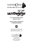
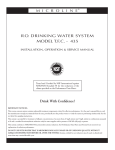
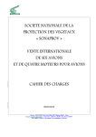
1
Single
Engine
SERVICE LETTER
SEL-24-02
TITLE
ELECTRICAL POWER - CONTACTOR REPLACEMENT
EFFECTIVITY
All Cessna Single Engine airplanes equipped with 12-volt and 24-volt contactors listed in this service letter.
REASON
To provide spares replacement for obsolete 12-volt and 24-volt contactors.
DESCRIPTION
To provide parts and instructions for replacement of obsolete 12-volt and 24-volt contactors with Lamar
contactors.
COMPLIANCE
OPTIONAL. This service letter can be accomplished at the discretion of the owner.
REFERENCES
Applicable Cessna Airplane Maintenance/Service Manuals and Illustrated Parts Catalogs
Cessna Service Kit SK210-173A (or latest revision), 28-Volt Starter Contactor Replacement
Lamar Technologies LLC Service Information Letter LSI-017 Revision A (or latest Cessna-approved
revision), Replacing the Cessna Contactors
Lamar Technologies LLC Service Information Letter LSI-018 Revision A (or latest Cessna-approved
revision), Replacing the Cessna Contactors
PUBLICATIONS AFFECTED
Applicable Cessna Airplane Maintenance/Service Manuals and Illustrated Parts Catalogs
ACCOMPLISHMENT INSTRUCTIONS
Applicable Cessna Service Kit and/or Lamar Technologies Service Information Letter installation instructions
are included with the contactor / contactor kits listed in the Material Information Section of this service letter
when they are shipped from Cessna Service Parts and Programs.
SEL-24-02
Page 1 of 2
April 4, 2013
Cessna Aircraft Company, Cessna Customer Service, P.O. Box 7706, Wichita, KS 67277, U.S.A. 1-316-517-5800, Fax 1-316-517-7271,
Email: [email protected]
This document contains technical data and is subject to U.S. export regulations. This information has been exported from the United States
in accordance with export administration regulations. Diversion contrary to U.S. law is prohibited. ECCN: 9A991
COPYRIGHT © 2013
Single
Engine
SERVICE LETTER
SEL-24-02
MATERIAL INFORMATION
NEW P/N
INSTALLATION
INSTRUCTIONS
P52-0016
KEY WORD
OLD P/N
INSTRUCTIONS/
DISPOSITION
SK210-173A
Contactor Kit, 24V
Intermittent Duty
S1577-1, S1577A1,
8781-8
Discard
X61-0030
Not Required/
Direct
Replacement
Contactor, 12V
Intermittent Duty
S2103-1, S2103A1,
111-139D
Discard
P52-0033
LSI-018, Rev A
Contactor Kit, 12V
Intermittent Duty
S1991-1, S1991A1,
111-138D, SAW4204-1,
SAW4206-1
Discard
P52-0034
LSI-018, Rev A
Contactor Kit, 12V
Continuous Duty
S1660-1, S1660A1,
8781-10
Discard
P52-0034-1
LSI-017, Rev A
Contactor Kit, 12V
Continuous Duty
S1579-1, S1579-2,
S1579A2, 111-140D
Discard
P52-0035-1
LSI-017, Rev A
Contactor Kit, 24V
Continuous Duty
S1580-1, S1580A1,
8781-9
Discard
SEL-24-02
Page 2
April 4, 2013
Single
Engine
OWNER ADVISORY
SEL-24-02
TITLE
ELECTRICAL POWER - CONTACTOR REPLACEMENT
TO:
Cessna Cessna Single Engine Classic Owner
REASON
This owner advisory is to inform you that SEL-24-02 has been issued.
SEL-24-02 provides provide parts and instructions for replacement of obsolete 12-volt and 24-volt
contactors with Lamar contactors.
COMPLIANCE
OPTIONAL. This service letter can be accomplished at the discretion of the owner.
LABOR HOURS
Not applicable
WARRANTY
Not Applicable
NOTE: As a convenience, service documents are now available online to all our customers through a
simple, free-of-charge registration process. If you would like to sign up, please visit the "Customer
Access" link at www.cessnasupport.com to register.
This owner advisory will not be mailed to airplane owners. It is provided as an attachment to this service letter.
SEL-24-02
Page 1 of 1
April 4, 2013
Cessna Aircraft Company, Cessna Customer Service, P.O. Box 7706, Wichita, KS 67277, U.S.A. 1-316-517-5800, Fax 1-316-517-7271,
Email: [email protected]
This document contains technical data and is subject to U.S. export regulations. This information has been exported from the United States
in accordance with export administration regulations. Diversion contrary to U.S. law is prohibited. ECCN: 9A991
COPYRIGHT © 2013
Single Engine
SERVICE KIT
SK210-173A
TITLE
28-VOLT STARTER CONTACTOR REPLACEMENT
EFFECTIVITY
Model
Year
Serial Numbers
152
1978
15279406 thru 15282031
152
1979
15282032 thru 15283591
A152
1978
A1520735 thru A1520808
A152
1979
A1520809 thru A1520878
172N
1978
17269310 thru 17270049
172N
1978
17270051 thru 17271034
172N
17261578
172N
1979
17271035 thru 17272884
R172E (T41)
1967 thru 1968
R172-0001 thru R172-0335
R172F (T41)
1969
R172-0336 thru R172-0409
R172G (T41)
1969 thru 1970
R1720410 thru R1720444
R172H (T41)
1971
R1720445 thru R1720494
R172H (T41)
1972
R1720495 thru R1720546
R172H (T41)
1973 thru 1976
R1720547 thru R1720620
R172K
1978
R1722725 thru R1722929
R172K
1979
R1722930 thru R1723199
177RG
1978
177RG1267 thru 177RG1366
177RG
177RG0419
180K
1978
18052906 thru 18053000
180K
1979
18053001 thru 18053082
182Q
1978
18265966 thru 18266590
182Q
1979
18266591 thru 18266977
R182
1978
R18200002 thru R18200583
R182/TR182
1979
R18200584 thru R18201089
A185F
1978
18503459 thru 18503683
A185F
1979
18503684 thru 18503846
October 1, 2009
Original Issue: April 17, 2006
Page 1 of 5
To obtain satisfactory results, procedures specified in this publication must be accomplished in accordance with accepted methods and
prevailing government regulations. Cessna Aircraft Company cannot be responsible for the quality of work performed in accomplishing the
requirements of this publication.
Cessna Aircraft Company, Customer Service, P.O. Box 7706, Wichita, Kansas 67277, U.S.A. (316) 517-5800, Facsimile (316) 942-9006
COPYRIGHT © 2006
SERVICE KIT
SK210-173A
A188B
1976
18802349 thru 18802745
A188B
1977
18802746 thru 18803046
A188B
1978
18803047 thru 18803296
A188B
1979
18803297 thru 18803472
A188B
1979
18803297T thru 18803472T
FR172K
1978
FR17200621 thru FR17200630
FR172K
1979
FR17200631 thru FR17200655
U206F/TU206F
1974
U20602200 thru U20602579
U206F/TU206F
1975
U20602580 thru U20602588
U206F/TU206F
1975
U20602590 thru U20603020
U206F/TU206F
1976
U20603021 thru U20603521
U206G/TU206G
1977
U20603522 thru U20604074
U206G/TU206G
1978
U20604075 thru U20604649
U206G/TU206G
1979
U20604650 thru U20605080
U206G/TU206G
Page 2
U20602589
207/T207
1974
20700228 thru 20700267
207/T207
1975
20700268 thru 20700314
207/T207
1976
20700315 thru 20700362
207A/T207A
1977
20700363 thru 20700414
207A/T207A
1978
20700415 thru 20700482
207A/T207A
1979
20700483 thru 20700538
210L/T210L
1972
21059503 thru 21059719
210L/T210L
1973
21059720 thru 21060089
210L/T210L
1974
21060090 thru 21060539
210L/T210L
1975
21060540 thru 21061039
210L/T210L
1976
21061040 thru 21061041
210L/T210L
1976
21061043 thru 21061573
210M/T210M
1977
21061574 thru 21062273
210M/T210M
1978
21062274 thru 21062954
210M/T210M
1978
21061042
210N/T210N
1979
21062955 thru 21063476
P210N
1978
P21000001 thru P21000150
P210N
1979
P21000151 thru P21000344
F152
1978
F15201429 thru F15201528
FA152
1978
FA1520337 thru FA1520347
FA152
1979
FA1520348 thru FA1520357
F172N
1978
F17201640 thru F17201749
SK210-173A
October 1, 2009
SERVICE KIT
SK210-173A
F172N
1979
F17201750 thru F17201909
F182Q
1978
F18200065 thru F18200094
F182Q
1979
F18200095 thru F18200129
FR182
1978
FR18200001 thru FR18200020
FR182
1979
FR18200021 thru FR18200045
FR182
1980
FR18200046 thru FR18200055
DESCRIPTION
To provide a spares replacement for the 28-volt starter contactor.
APPROVAL
FAA approval has been obtained on technical data in this publication that affects airplane type design.
CHANGE IN WEIGHT AND BALANCE
Negligible
MATERIAL INFORMATION
The part below covers installation for one airplane.
NEW P/N
QUANTITY
DESCRIPTION
SK210-173A
1
Kit, consisting of the
following parts:
P52-0016
1
28-Volt Starter Contactor
1
Instructions
OLD P/N
DISPOSITION
S1577-1,
S1577A1,
8781-8
Discard
ACCOMPLISHMENT INSTRUCTIONS
1.
Prepare the airplane for maintenance.
A.
Make sure that all switches are in the OFF/NORM position.
B.
Remove the upper engine cowl.
C.
Disconnect electrical power from the airplane.
D.
(1)
Disconnect the airplane battery.
(2)
Disconnect external electrical power.
Attach maintenance warning tags to the battery and external power receptacle that have "DO NOT
CONNECT ELECTRICAL POWER - MAINTENANCE IN PROGRESS" written on them.
SK210-173A
October 1, 2009
Page 3
SERVICE KIT
SK210-173A
CAUTION: Do not use the P52-0016 28-Volt Starter Contactor to replace contactors in the airplane
other than those in the starter system. If you replace a contactor other than a starter
contactor with the P52-0016 28-Volt Starter Contactor, damage to the equipment will occur.
2.
Get access to the 28-volt starter contactors on the left side of the forward engine firewall. (Refer to
the applicable sections of the Service Manual.)
NOTE: To find the contactors, follow the starter power cable from the starter to the contactor.
3.
(Refer to Figure 1.) Remove and discard the 28-volt starter contactor. Keep the hardware that attaches
the starter contactor to the firewall. (Refer to the applicable sections of the Service Manual.)
4.
With the kept attachment hardware, install the new P52-0016 28-Volt Starter Contactor to the firewall.
(Refer to the applicable sections of the Service Manual.)
CAUTION: Make sure that you install the wires to the same terminal studs as shown in Figure
1. If you install the wires in a different configuration than the one shown in Figure 1,
damage to the system may occur.
A.
As you install the contactor, install the loose end of the ground wire that is attached to the contactor
under one of the contactor mount bolts to provide a ground for the contactor coil.
CAUTION: If the airplane has a diode wire, do not replace the diode wire with a standard
ground wire. If you replace the diode wire with a standard ground wire, damage to
the system may occur.
CAUTION: If the airplane has a diode wire, do not install the diode wire on the same terminal
stud with the ground wire. If you install the diode wire and the ground stud wire on the
same terminal stud, damage to the system may occur.
B.
If the airplane has a diode wire, install it on the new starter contactor. Install it on a different terminal
stud than the one on which the ground wire is installed.
5.
Install the upper engine cowl.
6.
Remove maintenance warning tags and connect the airplane battery.
7.
Make an entry in the airplane logbook stating this service kit has been installed.
Page 4
SK210-173A
October 1, 2009
SERVICE KIT
SK210-173A
Figure 1. 28-Volt Starter Contactor Replacement (Sheet 1)
SK210-173A
October 1, 2009
Page 5
Cessna Aircraft Company Proprietary Information
CONTACTOR KITS
Issued: 1/17/2013
REPLACING THE CESSNA CONTACTORS
SERVICE INFORMATION LETTER
SUBJECT:
This letter is to provide wiring installation instructions for Lamar P/N P52-0034-1 (12V
Contactor kit) and Lamar P/N P52-0035-1 (24V Contactor kit) as a replacement for the
Cessna P/N S1579 (12V) and S1580 (24V) contactors. These instructions shall be printed
and distributed in the packaging with each contactor kit.
REASON:
To provide clarification of contactor terminal definition for installing on aircraft.
INFORMATION: Reference Figure shown below. The Lamar contactor kit will come with a red jumper wire
installed from the Battery Terminal to the Coil Power Terminal. This jumper shall convert a
4 terminal contactor for replacement of a 3 terminal contactor. 3 terminal contactors (S1579
and S1580) have this connection inside the contactor without a coil power terminal. Aircraft
wiring must control (on or off) the contactor coil through the Coil Ground Terminal and not
have any wires (except jumper) attached to the Coil Power Terminal.
For technical support call Cessna Customer Care at 316-517-5800
FIGURE:
Coil Power Terminal
(DO NOT connect
aircraft wires here)
Coil Ground
Terminal
Battery
Terminal
Load
Terminal
Red
Jumper
Wire
LSI-017 REV: A
RELEASE DATE: 1/17/13
Printed On 02/06/2013
PAGE 1 OF 1
Cessna Aircraft Company Proprietary Information
CONTACTOR KITS
Issued: 1/17/2013
REPLACING THE CESSNA CONTACTORS
SERVICE INFORMATION LETTER
SUBJECT:
This letter is to provide wiring installation instructions for Lamar P/N P52-0033 (12V
Intermittent Duty Contactor kit) and Lamar P/N P52-0034 (12V Continuous Duty Contactor
kit) as a replacement for the Cessna P/N S1991 (Intermittent Duty) and S1660 (Continuous
Duty) contactors. These instructions shall be printed and distributed in the packaging with
each contactor kit.
REASON:
To provide clarification of contactor terminal definition for installing on aircraft.
INFORMATION: Reference Figure shown below. The Lamar contactor kit will come with a black jumper wire
with one end installed on the Coil Ground Terminal. This jumper when connected to the
airframe ground (as shown) shall convert a 4 terminal contactor for replacement of a 3
terminal contactor. 3 terminal contactors (S1991 and S1660) have this connection inside
the contactor without a Coil Ground Terminal. Aircraft wiring must control (on or off) the
contactor coil through the Coil Power Terminal and not have any wires (except jumper)
attached to the Coil Ground Terminal.
For technical support call Cessna Customer Care at 316-517-5800
FIGURE:
Coil Ground Terminal
(do not connect
aircraft wires here)
Coil Power
Terminal
Battery
Terminal
Load
Terminal
Black
Jumper
Wire
LSI-018 REV: A
RELEASE DATE: 1/17/13
Printed On 02/06/2013
PAGE 1 OF 1