1
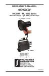
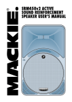
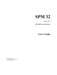
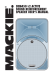
ALERT SERVICE
BULLETIN
ASB221E
January 28, 2010
TITLE
INSPECTION OF MODEL 1A103/TCM PROPELLER HUB FOR CRACKING AND REWORK PROCEDURES
TO:
FAA-Approved Propeller Repair Stations, Cessna Aircraft Company, Aircraft Owners, and Operators
MODELS AFFECTED
1A103/TCM (All Serial Numbers)
NOTE: This bulletin does not contain an exhaustive list of aircraft which utilize this propeller because it is not
possible to identify all aircraft using the affected propeller model (e.g. installation approvals made by
Supplemental Type Certificate or FAA Form 337 Major Repair and Alteration, or Type Certificated
models which have been inadvertently omitted). Therefore, it is the responsibility of the operator
or person(s) performing aircraft inspections/propeller overhauls to determine if an aircraft has an
affected propeller.
AIRCRAFT AFFECTED
Cessna 152, A152; Reims F152, FA152
PUBLICATIONS AFFECTED
McCauley 730720 Fixed Pitch Overhaul Manual
McCauley Standard Practices Manual SPM100
REASON
McCauley has received reports of cracks in the 1A103/TCM model propeller hub. Cracks have been found
on the camber side of the propeller hub near the mounting bolt holes. These crack(s) have been observed
primarily in areas where fretting is present around propeller mounting bolt holes.
McCauley has recently received reports of model 1A103/TCM propellers, with serial numbers that were not
affected by Alert Service Bulletin 221C, that had cracks in the propeller hub.
Original Issue: November 5, 1996
Page 1 of 19
TO OBTAIN SATISFACTORY RESULTS, PROCEDURES SPECIFIED IN THIS SERVICE INFORMATION MUST BE ACCOMPLISHED IN
ACCORDANCE WITH ACCEPTED METHODS AND PREVAILING GOVERNMENT REGULATIONS. MCCAULEY PROPELLER SYSTEMS
CANNOT BE RESPONSIBLE FOR THE QUALITY OF WORK PERFORMED IN ACCOMPLISHING THIS SERVICE INFORMATION.
McCauley Propeller Systems
PO Box 7704
Wichita, Kansas 67277-7704
COPYRIGHT © 1996 McCauley Propeller Systems
ALERT SERVICE
BULLETIN
ASB221E
DESCRIPTION
Alert Service Bulletin ASB221E does the following:
1.
Provides additional inspection procedures for the propeller bolt holes.
2.
Added inspections for the propeller steel reinforcement plate and the mylar gasket.
3.
Miscellaneous changes to increase bulletin clarity.
4.
Alert Service Bulletin ASB221E supersedes all previous versions of Alert Service Bulletin 221.
COMPLIANCE
MANDATORY. All inspection and replacement requirements must be done at the compliance times and
intervals shown below.
1.
For propellers with 1500 hours or more total time in service or if the propeller total time in service is
unknown:
a)
Inspection and rework procedures must be done within the next 50 hours of service.
NOTE: For propellers that have previously been inspected in accordance with Alert Service
Bulletin 221C or of Alert Service Bulletin ASB221D, compliance with the initial
inspection requirements of Alert Service Bulletin ASB221E is not required.
2.
For propellers with less than 1500 hours total time in service:
a)
3.
Inspection and rework procedures must be done at 1500 hours total time in service or within
the next 50 hours of service, whichever occurs later.
Repetitive Inspections:
a)
After completing the initial inspection of the propeller, steel reinforcement plate, and mylar
gasket, repetitive inspections must be accomplished every 36 calendar months or every 750
hours of service, whichever occurs first.
APPROVAL
FAA approval has been obtained on technical data in this publication that affects product type design.
Page 2
ASB221E
January 28, 2010
ALERT SERVICE
BULLETIN
ASB221E
EQUIPMENT REQUIRED
NOTE: Equivalent substitutes can be used for the following materials or equipment. All penetrant materials
must be listed in the current version of QPL-AMS-2644.
NAME
NUMBER
MANUFACTURER
USE
Liquid Penetrant
Type I, Method
C, Level 4
Ultra-High
Sensitivity
Magnaflux
3624 West Lake Avenue
Glenview, IL 60026
www.magnaflux.com
Penetrant inspection
Radiometer
DSE 2000A
Spectronics Corp.
956 Brush Hollow Rd.
Westbury, NY 11590
www.spectroline.com
Measure light intensity
Ultraviolet Light
ZB-100F
Magnaflux
To do penetrant
inspection
LIGHTING EQUIPMENT/ENVIRONMENT
1.
The penetrant inspection must be done in a darkened environment where the ambient white light intensity
is not more than 2 fc (foot candles). In order for Type I penetrant materials to fluoresce, they must be
exposed to ultraviolet light with a wavelength of 320 to 380 nanometers.
A.
The black light must produce a minimum light intensity of 2,000 µW/cm2 at a distance of 15 inches
from the face of the ultraviolet light filter to the sensor on the ultraviolet light meter. Let the black light
warm up for a minimum of 10 minutes before use.
WARNING:
B.
PERSONNEL MUST NOT WEAR LIGHT SENSITIVE
(PHOTOCHROMIC) LENSES DURING THE INTERPRETATION/
EVALUATION OF PARTS.
Both the ultraviolet light and ambient light intensities must be measured with a calibrated light
meter before each inspection.
NOTE: It is recommended that the inspector allow 3 minutes for the eyes to adapt to the dark
before the interpretation/evaluation of parts.
C.
Do the inspection in accordance with standard ASTM E 1417, Standard Practice for Liquid Penetrant
Examination, or international equivalent, except for dwell time.
(1)
D.
The penetrant dwell time must be a minimum of 60 minutes.
Materials used to do this inspection must be in accordance with the current version of
QPL-AMS-2644, Qualified Products of Inspection Material, Penetrant, or international equivalent.
CAUTION: ALL MATERIALS USED IN A PROCESS MUST BE FROM THE SAME FAMILY
GROUP.
E.
Penetrants used must be Type I, Fluorescent dye, Level 4 sensitivity.
PERSONNEL REQUIREMENTS
Individuals performing the inspections defined in this service bulletin must be an employee of an FAA approved
facility or international equivalent with a specialized service rating in the applicable inspection method.
Employees must be qualified and certified to the minimum recommended requirements of "Level II" as described
in Aerospace Industrial Standard NAS 410, ASNT’s SNT-TC-1A, or equivalent national/international standard.
ASB221E
January 28, 2010
Page 3
ALERT SERVICE
BULLETIN
ASB221E
ACCOMPLISHMENT INSTRUCTIONS
NOTE: Make sure you read and understand all of the instructions in this service bulletin before the work to
comply with this service bulletin is started.
1.
Preparation
A.
B.
Remove the propeller from the airplane.
(1)
For propellers that are not in compliance with previous revisions of this service bulletin, refer to
the Cessna 152 Series Service Manual and Figure 13.
(2)
For propellers that are in compliance with previous revisions of this service bulletin, refer to the
Cessna 152 Series Service Manual and Figure 14.
Strip paint from the propeller hub area.
(1)
There should be no paint on the face (aft) side of the propeller hub. If there is, make sure all
paint in that area is removed. Remove the paint from the camber (forward) side of the propeller
hub. Make sure all paint is removed from the hub area of the propeller. Refer to Figure 12. for
an illustration of the inspection area on the camber (forward) side of the propeller.
(a)
C.
2.
Remove paint. Refer to the Standard Practices Manual, Cleaning Procedures 60-00-01,
Paint Removal.
Caustic etch the inspection area of the propeller hub. Refer to Standard Practices Manual,
Nondestructive Inspection Procedures 60-00-03, Caustic Soda Etch.
(1)
Make sure the anodize coating has been removed from the inspection area.
(2)
Make sure there are no burrs or other metal obstructions on the area to be inspected on the
propeller hub.
Inspection
NOTE: For the purposes of this inspection, the chamfered area around each bolt hole is considered a
part of the bolt hole.
A.
Determine condition of all propeller bolt holes.
(1)
Visually examine the propeller bolt holes with a 10X power magnifying glass.
(a)
Make sure there is sufficient light available to illuminate each propeller bolt hole. If
required, use a flashlight or similar light source to illuminate each propeller bolt hole.
(b)
Make sure there are no burrs or other metal obstructions in the propeller bolt holes. If
burrs and scratches are detected, remove the burrs and scratches in accordance with
the following instructions:
1
Ream bolt hole to a diameter of 0.406 inch, +0.002 or - 0.002 inches (10.31 mm,
+0.05 or -0.05 mm).
NOTE: The entire length of the bolt hole must be reamed.
NOTE: Reaming may not result in a smooth bolt hole surface throughout the entire
length of the bolt hole.
NOTE: This procedure does not affect the 0.636 inch +0.003 or -0.002 inch (16.15
mm, +0.08 or -0.05 mm) bolt hole counterbore on the aft face of the
propeller hub (crankshaft mounting surface).
(c)
Visually examine all bolt holes that have been reamed to 0.406 inch (10.31 mm) diameter.
1
Page 4
Make sure the first 0.375 inches (9.53 mm) (as measured from the hub
camber/forward side) of the reamed bolt hole is smooth and does not have any
burrs or scratches.
ASB221E
January 28, 2010
ALERT SERVICE
BULLETIN
ASB221E
2
If the reamed bolt hole has a drill tear line or scratch, it is permissible to sand the
hole in this area smooth with 400 grit sandpaper.
NOTE: Drill tear lines or scratches that are observed 0.375 inch (9.53 mm) or more
from the propeller camber/forward side surface are acceptable, no action is
required for this observation.
(2)
Measure the diameter of all bolt holes that were sanded smooth.
4
The maximum out-of-round hole diameter in the area of the sanded repair must not
exceed 0.420 inch (10.67 mm).
5
Remove from service any propeller with an out-of-round bolt hole diameter greater
than 0.420 inch (10.67 mm).
Measure the bolt hole wall thickness.
(a)
B.
3
Use a calipers or similar measuring device, measure the wall thickness of all bolt holes
to the outside of the propeller hub wall 0.375 inches (9.53 mm) from the propeller hub
camber/forward side surface. Remove from service any propeller that has a measured
wall thickness less than 0.280 inches (7.11 mm) at a depth of 0.375 inches (9.53 mm)
from the propeller hub camber/forward side surface.
Do a Fluorescent Dye Penetrant inspection of the hub area. The fluorescent dye penetrant
inspection must also include the first 0.375 inches (9.53 mm) (as measured from the hub
camber/forward side) bolt holes. Refer to Standard Practices Manual, Nondestructive Inspection
Procedures 60-00-03, Fluorescent Dye Penetrant Inspection.
NOTE: This inspection deviates from the Standard Practices Manual, Nondestructive Inspection
Procedures 60-00-03 in the following areas:
(1)
•
The liquid penetrant must be a Type I, with a Level 4 Ultra High Sensitivity.
•
The penetrant dwell time must be a minimum of 60 minutes.
•
The black light must produce a minimum light intensity of 2,000 µW/cm2 at a distance
of 15 inches.
If a crack is found, check the propeller serial number for change letter stamping. If a letter
"S" is located in front of the serial number (indicating prior rework), the area of the previous
rework must be determined.
(a)
If the change letter "S" is not present or previous rework was at a different bolt hole, mark
the location of the crack, path, and length with a fine point felt tip pen prior to removing
the ultraviolet light.
NOTE: Marking the area of the crack indication prior to removing the ultraviolet light is
important for aiding rework if the crack size and location are found to be within
acceptable limits.
(2)
If you find any of the of the following conditions, the propeller must be removed from service
(Refer to Figure 11.):
(a)
Crack(s) in the camber (forward) side of the hub are 0.50 inch (13 mm) or longer.
(b)
Crack(s) in the camber (forward) side of the hub touch a bolt hole.
(c)
Any crack on the camber (forward) side of the hub that is within 0.25 inch (6.4 mm)
of the outside edge of the hub.
(d)
Any crack on the camber (forward) side of the hub that is within 0.25 inch (6.4 mm) of the
outside edge of the center bore.
(e)
A crack in any part of a propeller bolt hole (including the chamfered surfaces and any
depth).
ASB221E
January 28, 2010
Page 5
ALERT SERVICE
BULLETIN
ASB221E
(f)
The change letter "S" is stamped in front of the propeller serial number, and the location
of the previous rework cannot be determined.
(g)
The change letter "S" is stamped in front of the propeller serial number, and the crack
is adjacent to a bolt hole that was previously reworked by Alert Service Bulletin 221,
221B or 221C.
(h)
Any part of a crack that cannot be removed by the procedures in this Service Bulletin.
NOTE: The McCauley 1A103/TCM model propeller is no longer available from McCauley.
Replacement Sensenich propellers and STC information are available for the Cessna
Model 152, A152 and Reims Model F152 and FA152 airplanes. The replacement
Sensenich propeller installation STC and necessary parts are available from McCauley
Service Centers and Cessna Single Engine Service Stations.
(3)
If you find a small crack(s) on the camber (forward) side of the hub (near the bolt holes) that
meet the following criteria, the propeller can be reworked and the crack(s) must be removed.
Refer to Figure 1 and Figure 11.
Figure 1. Crack Identification
(a)
(4)
C.
1
Crack(s) in the camber (forward) side of the hub are less than 0.50 inch (13 mm)
long.
2
Crack(s) in the camber (forward) side of the hub do not touch a bolt hole.
3
No part of the camber (forward) side of the hub crack is within 0.25 inch (6.4 mm)
of the outside edge of the hub.
4
No part of the camber (forward) side of the hub crack is within 0.25 inch (6.4 mm)
of the outside edge of the center bore.
5
If the propeller has previously been reworked, the crack is located adjacent to a
different bolt hole than one that has previously been reworked.
Proceed to Step 3, Hub Camber (Forward) Side Crack Removal Procedure.
If no crack is found.
(1)
Page 6
All of the following criteria must be met in order for the propeller to be eligible for rework:
Glass shot peen the entire camber side of the hub, use AGB-18 glass shot (AMS2431/6B or
latest revision, 80-100 PSI. An approved alternate is: MSH glass shot in accordance with
MIL-G-9954A or latest revision, MIL Bead #8).
ASB221E
January 28, 2010
ALERT SERVICE
BULLETIN
ASB221E
(2)
Corrosion protect the propeller.
(a)
Apply color chemical film treatment to all bare surfaces of the propeller that came in
contact with the caustic etch solution. Refer to the Standard Practices Manual, Protective
Treatments 60-00-04, Chemical Conversion Film Coating.
NOTE: Make sure the chemical film treatment is swabbed inside the bolt holes where
etching solution may have entered.
Or
(b)
(3)
Anodize the propeller. Refer to the Standard Practices Manual, Protective Treatments
60-00-04, Anodize.
Repaint the propeller hub. Refer to the Standard Practices Manual, Paint Instructions 60-00-06.
Do not paint the engine mounting surface (face/aft side) of the hub within the dimensioned
area as shown in Figure 12.
NOTE: Figure 12. is an illustration of the camber (forward) side of the propeller, transfer
the dimensioned area shown to the engine mounting surface (face/aft side) of the
propeller hub.
(4)
3.
Proceed to Step 4. Steel Reinforcement Plate Inspection.
Hub Camber (Forward) Side Crack Removal Procedure
A.
Crack Removal
(1)
OPTION 1 - Bridgeport (Refer to Figure 2.)
(a)
Lay the propeller on a Bridgeport Mill (or similar machine).
(b)
Align and center the crack with a 0.250 inch ball end mill in the direction of motion.
Figure 2. Alignment of Bridgeport Mill
(c)
Clamp the propeller to the machine table.
(d)
Lower the 0.250 inch ball end mill and touch hub surface. This will be the zero (0)
dimension (Refer to Figure 3.).
ASB221E
January 28, 2010
Page 7
ALERT SERVICE
BULLETIN
ASB221E
Figure 3. Zero Dimension
(e)
Set depth of first cut to 0.010 inch, and begin removal of the crack. (Refer to Figure 4.)
NOTE: Final depth of cut must not exceed 0.040 inch total when attempting to remove
a crack.
NOTE: The ball end mill may extend into the bolt hole when you remove the crack. Do
not allow the mill centerline to extend beyond the length of crack. This will allow
for end mill runout. (Refer to figure 4.)
Figure 4. Initial Material Removal
(f)
Page 8
Examine reworked area under 10x magnification after each cut. (Refer to Figure 5.)
ASB221E
January 28, 2010
ALERT SERVICE
BULLETIN
ASB221E
Figure 5. Final Machining
(2)
(g)
If the crack appears to be totally removed, repeat etch and fluorescent dye penetrant
inspection of the reworked area to make sure the crack has been removed.
(h)
If the crack extends beyond a depth of 0.040 inch, the propeller must be removed
from service.
OPTION 2 - Rotary Grinder (Refer to Figure 6.)
(a)
Use a 3/16 inch grinding burr, and begin to remove the crack.
Figure 6. Crack Removal Using a Grinding Burr
NOTE: Do not remove more than 0.040 inch material total when attempting to remove
a crack.
NOTE: Do not grind beyond length of crack.
NOTE: The grinding burr may extend into the bolt hole when you remove the crack. Do
not allow the grinding burr centerline to extend beyond the length of the crack.
This will allow for grinding burr runout. (Refer to figure 4.)
(b)
ASB221E
January 28, 2010
Measure the depth of material removed with a depth gauge.
Page 9
ALERT SERVICE
BULLETIN
ASB221E
(c)
Examine reworked area under 10X magnification after each cut.
(d)
If crack appears to be totally removed, repeat etch and fluorescent dye penetrant
inspection of the reworked area to make sure the crack has been removed. (Refer to
Figure 7.)
(e)
If the crack extends beyond a depth of 0.040 inch, the propeller must be removed
from service.
Figure 7. After Machining
B.
Sand the camber (forward) side of the hub.
(1)
Sand the camber (forward) side of the hub with sanding bob (Cratex Rubberized Abrasives,
part number 11M) to remove any sharp edges. (Refer to Figure 8 and Figure 9.)
Figure 8. Sand Edges of Machining
Page 10
ASB221E
January 28, 2010
ALERT SERVICE
BULLETIN
ASB221E
Figure 9. After Sanding
C.
Glass shot peen the hub.
(1)
Glass shot peen the entire hub, use AGB-18 glass shot (AMS2431/6B or latest revision, 80-100
PSI. An approved alternate is: MSH glass shot in accordance with MIL-G-9954A or latest
revision, MIL Bead #8). (Refer to Figure 10.)
Figure 10. Shot Peened Surface
D.
Stamp change letter ’S’.
(1)
Stamp change letter ’S’, using a 1/8 inch steel stamp, in front of the propeller serial number.
NOTE: If the change letter has been previously stamped, a second stamp is not necessary.
ASB221E
January 28, 2010
Page 11
ALERT SERVICE
BULLETIN
ASB221E
E.
Corrosion protect the propeller.
(1)
Apply color chemical film treatment to all bare surfaces of the propeller that came in contact
with the caustic etch solution. Refer to the Standard Practices Manual, Protective Treatments
60-00-04, Chemical Conversion Film Coating.
NOTE: Make sure the chemical film treatment is swabbed inside the bolt holes where etching
solution may have entered.
Or
(2)
F.
Anodize the propeller. Refer to the Standard Practices Manual, Protective Treatments
60-00-04, Anodize.
Repaint the propeller hub. Refer to the Standard Practices Manual, Paint Instructions 60-00-06. Do
not paint the engine mounting surface of the hub within the dimensioned area as shown in Figure 12.
NOTE: Figure 12. is an illustration of the camber (forward) side of the propeller, transfer the
dimensioned area shown to the engine mounting surface (face/aft side) of the propeller hub.
Page 12
ASB221E
January 28, 2010
ALERT SERVICE
BULLETIN
ASB221E
Figure 11. Reworkable and Non-Reworkable Cracks (Sheet 1)
ASB221E
January 28, 2010
Page 13
ALERT SERVICE
BULLETIN
ASB221E
Figure 12. Typical Crack Appearance and Location (Sheet 1)
Page 14
ASB221E
January 28, 2010
ALERT SERVICE
BULLETIN
ASB221E
Figure 13. Original Configuration of 1A103/TCMXXXX Propeller and Spinner Installation (Sheet 1)
ASB221E
January 28, 2010
Page 15
ALERT SERVICE
BULLETIN
ASB221E
Figure 14. Reworked Configuration for 1A103/TCMXXXX Propeller and Spinner Installation (Sheet 1)
Page 16
ASB221E
January 28, 2010
ALERT SERVICE
BULLETIN
ASB221E
4.
Steel Reinforcement Plate Inspection
A.
Do a visual inspection of the B-7287 steel reinforcement plate.
(1)
(2)
B.
5.
Cadmium plating
(b)
Zinc phosphate
(c)
Zinc nickel
No defects are permitted.
No defects are permitted.
Remove from service any part that has a visible defect or a defect made apparent by the magnetic
particle inspection.
Mylar Gasket Inspection
A.
6.
(a)
Do a magnetic particle inspection on the B-7287 steel reinforcement plate. Refer to the Standard
Practices Manual, Section 60-00-03, Non-Destructive Inspection for inspection procedures.
(1)
C.
If the cadmium plating is worn, replate the part in accordance with the Standard Practices
Manual, Section 60-00-04, Protective Treatments. The following protective treatments are
approved for this part:
Do a visual inspection of the B-7306 mylar gasket.
(1)
No defects are permitted.
(2)
Remove from service any gasket that has a visible defect.
Reassembly
A.
Install propeller (refer to Figure 14.)
(1)
Clean mating surface of propeller, crankshaft flange, and spinner bulkheads.
WARNING:
BE SURE THAT MAGNETO IS GROUNDED BEFORE TURNING
PROPELLER OR CONNECTING EXTERNAL POWER.
(2)
Put the aft spinner bulkhead between propeller and crankshaft flange.
(3)
Align propeller blade with t.c. mark on aft side of ring gear, and rotate propeller clockwise, as
viewed from the front, to the first bolt hole.
(4)
Install B-7306 mylar gasket between the hub and the forward spinner bulkhead.
(5)
Install forward spinner bulkhead.
(a)
If the holes on the forward spinner bulkhead are cupped, bulkhead deformation is the
result of installation torques from propeller bolts and washers, put the bulkhead on a flat
surface and lightly work the cupped holes flat with a hammer.
(b)
Remove any burrs or rough edges. Diameter of holes should be 0.397 inches, +0.10 or
-0.10 inches.
(c)
Ream holes if necessary.
(d)
Remove from service any forward spinner bulkhead that has a bolt hole that is greater
than 0.407 inches in diameter.
(6)
Install B-7287 steel reinforcement plate on the forward side of the forward spinner bulkhead.
(7)
Install new bolts, A-2513-78, or bolts magnafluxed in accordance with ASTM E1444-91,
without washers.
NOTE: Bolts, plate and gasket can be purchased in kit form, the kit number is B-4622-43.
(8)
Tighten bolts evenly, then torque to 300-360 inch-pounds or 25-30 foot.-pounds (dry).
ASB221E
January 28, 2010
Page 17
ALERT SERVICE
BULLETIN
ASB221E
(9)
Safety wire propeller mounting bolts, make sure the safety wire is around the bolt heads, not
over the top. Use 0.041 inch diameter safety wire.
(10) Install the spinner shell.
B.
Report the inspection findings to McCauley.
(1)
Make sure the Attachment, Report Form for Compliance with McCauley Alert Service Bulletin
ASB221E is completed. The completed form can be mailed or telefaxed to McCauley at
the following address:
McCauley Propeller Systems
Product Support Department
P.O. Box 7704
Wichita, Kansas 67277–7404
Fax: (316) 831–3858
Phone: (316) 831–4021
C.
Page 18
Make a logbook entry stating compliance with this service bulletin, include details of inspection
results, and when the next inspection is due.
ASB221E
January 28, 2010
ALERT SERVICE
BULLETIN
ASB221E
ASB221E
January 28, 2010
Page 19