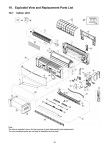
1
Order No: PAPAMY1303055AE Air Conditioner Indoor Unit CS-E9GFEW CS-E12GFEW CS-E18GFEW CS-E9GFEW-2 CS-E12GFEW-2 Outdoor Unit CU-E9PFE CU-E12PFE CU-E18PFE CU-E9PFE CU-E12PFE Destination Europe Please file and use this manual together with the Service Manual for Model No. CS-E9GFEW, CS-E12GFEW, CS-E18GFEW, CS-E9GFEW-2, CS-E12GFEW-2, Order No. RAC0704001C2, MAC0802015C2, MAC0804027A2. WARNING This service information is designed for experienced repair technicians only and is not designed for use by the general public. It does not contain warnings or cautions to advise non-technical individuals of potential dangers in attempting to service a product. Products powered by electricity should be serviced or repaired only by experienced professional technicians. Any attempt to service or repair the products dealt with in this service information by anyone else could result in serious injury or death. PRECAUTION OF LOW TEMPERATURE In order to avoid frostbite, be assured of no refrigerant leakage during the installation or repairing of refrigerant circuit. © Panasonic Corporation 2013. TABLE OF CONTENTS 1. Safety Precautions .............................................3 2. Specifications .....................................................5 3. Location of Controls and Components ..........14 3.1 3.2 3.3 Indoor Unit ..................................................14 Outdoor Unit ...............................................14 Remote Control ..........................................14 4. Dimensions .......................................................15 4.1 Outdoor Unit ...............................................15 5. Refrigeration Cycle Diagram ...........................17 5.1 5.2 CU-E9PFE CU-E12PFE ............................17 CU-E18PFE ................................................18 6. Block Diagram ..................................................19 6.1 6.2 CU-E9PFE CU-E12PFE ............................19 CU-E18PFE ................................................20 7. Wiring Connection Diagram ............................21 7.1 Outdoor Unit ...............................................21 8. Electronic Circuit Diagram ..............................23 8.1 Outdoor Unit ...............................................23 9. Printed Circuit Board .......................................25 9.1 Outdoor Unit ...............................................25 10. Installation Instruction .....................................28 10.1 10.2 Indoor Unit ..................................................28 Outdoor Unit ...............................................36 11. Protection Control ............................................40 11.1 11.2 11.3 Protection Control For All Operations.........40 Protection Control For Cooling & Soft Dry Operation ....................................................42 Protection Control For Heating Operation ....................................................43 12. Disassembly and Assembly Instructions ......44 12.1 Outdoor Electronic Controller Removal Procedure ...................................................44 13. Technical Data ..................................................47 13.1 13.2 Operation Characteristics ...........................47 Sensible Capacity Chart .............................59 14. Exploded View and Replacement Parts List .....................................................................60 14.1 Outdoor Unit ...............................................60 2 1. Safety Precautions Read the following “SAFETY PRECAUTIONS” carefully before perform any servicing. Electrical work must be installed or serviced by a licensed electrician. Be sure to use the correct rating of the power plug and main circuit for the model installed. The caution items stated here must be followed because these important contents are related to safety. The meaning of each indication used is as below. Incorrect installation or servicing due to ignoring of the instruction will cause harm or damage, and the seriousness is classified by the following indications. WARNING This indication shows the possibility of causing death or serious injury. CAUTION This indication shows the possibility of causing injury or damage to properties. The items to be followed are classified by the symbols: This symbol denotes item that is PROHIBITED from doing. Carry out test run to confirm that no abnormality occurs after the servicing. Then, explain to user the operation, care and maintenance as stated in instructions. Please remind the customer to keep the operating instructions for future reference. WARNING 1. Do not modify the machine, part, material during repairing service. 2. If wiring unit is supplied as repairing part, do not repair or connect the wire even only partial wire break. Exchange the whole wiring unit. 3. Do not wrench the fasten terminal. Pull it out or insert it straightly. 4. Engage dealer or specialist for installation and servicing. If installation of servicing done by the user is defective, it will cause water leakage, electrical shock or fire. 5. Install according to this installation instructions strictly. If installation is defective, it will cause water leakage, electric shock or fire. 6. Use the attached accessories parts and specified parts for installation and servicing. Otherwise, it will cause the set to fall, water leakage, fire or electrical shock. 7. Install at a strong and firm location which is able to withstand the set’s weight. If the strength is not enough or installation is not properly done, the set will drop and cause injury. 8. For electrical work, follow the local national wiring standard, regulation and the installation instruction. An independent circuit and single outlet must be used. If electrical circuit capacity is not enough or defect found in electrical work, it will cause electrical shock or fire. 9. 10. 11. This equipment is strongly recommended to install with Earth Leakage Circuit Breaker (ELCB) or Residual Current Device (RCD). Otherwise, it may cause electrical shock and fire in case equipment breakdown or insulation breakdown. Do not use joint cable for indoor / outdoor connection cable. Use the specified Indoor/Outdoor connection cable, refer to installation instruction CONNECT THE CABLE TO THE INDOOR UNIT and connect tightly for indoor / outdoor connection. Clamp the cable so that no external force will be acted on the terminal. If connecting or fixing is not perfect, it will cause heat up or fire at the connection. Wire routing must be properly arranged so that control board cover is fixed properly. If control board cover is not fixed perfectly, it will cause heat-up or fire at the connection point of terminal, fire or electrical shock. 12. When install or relocate air conditioner, do not let any substance other than the specified refrigerant, eg. air etc. mix into refrigeration cycle (piping). (Mixing of air etc. will cause abnormal high pressure in refrigeration cycle and result in explosion, injury etc.). 13. Do not install outdoor unit near handrail of veranda. When installing air-conditioner unit at veranda of high rise building, child may climb up to outdoor unit and cross over the handrail and causing accident. 14. This equipment must be properly earthed. Earth line must not be connected to gas pipe, water pipe, earth of lightning rod and telephone. Otherwise, it may cause electric shock in case equipment breakdown or insulation breakdown. 15. Keep away from small children, the thin film may cling to nose and mouth and prevent breathing. 16. Do not use unspecified cord, modified cord, joint cord or extension cord for power supply cord. Do not share the single outlet with other electrical appliances. Poor contact, poor insulation or over current will cause electrical shock or fire. 17. 18. 19. Tighten the flare nut with torque wrench according to specified method. If the flare nut is over-tightened, after a long period, the flare may break and cause refrigerant gas leakage. For R410A model, use piping, flare nut and tools which is specified for R410A refrigerant. Using of existing (R22) piping, flare nut and tools may cause abnormally high pressure in the refrigerant cycle (piping), and possibly result in explosion and injury. Thickness or copper pipes used with R410A must be more than 0.8 mm. Never use copper pipes thinner than 0.8 mm. It is desirable that the amount of residual oil less than 40 mg/10 m. During installation, install the refrigerant piping properly before run the compressor. (Operation of compressor without fixing refrigeration piping and valves at opened condition will caused suck-in of air, abnormal high pressure in refrigeration cycle and result in explosion, injury etc). 3 WARNING 20. During pump down operation, stop the compressor before remove the refrigeration piping. (Removal of compressor while compressor is operating and valves are opened will cause suck-in of air, abnormal high pressure in refrigeration cycle and result in explosion, injury etc.) 21. After completion of installation or service, confirm there is no leakage or refrigerant gas. It may generate toxic gas when the refrigerant contacts with fire. 22. Ventilate if there is refrigerant gas leakage during operation. It may cause toxic gas when refrigerant contacts with fire. 23. Do not insert your fingers or other objects into the unit, high speed rotating fan may cause injury. 24. Must not use other parts except original parts described in catalog and manual. 25. Using of refrigerant other than the specified type may cause product damage, burst and injury etc. CAUTION 1. Do not install the unit at place where leakage of flammable gas may occur. In case gas leaks and accumulates at surrounding of the unit, it may cause fire. 2. Carry out drainage piping as mentioned in installation instructions. If drainage is not perfect, water may enter the room and damage the furniture. 3. Tighten the flare nut with torque wrench according to specified method. If the flare nut is over-tightened, after a long period, the flare may break and cause refrigerant gas leakage. 4. Do not touch outdoor unit air inlet and aluminium fin. It may cause injury. 5. Select an installation location which is easy for maintenance. 6. 7. 8. Pb free solder has a higher melting point than standard solder; typically the melting point is 50°F – 70°F (30°C – 40°C) higher. Please use a high temperature solder iron. In case of the soldering iron with temperature control, please set it to 700 ± 20°F (370 ± 10°C). Pb free solder will tend to splash when heated too high (about 1100°F / 600°C). Power supply connection to the room air conditioner. Use power supply cord 3 x 1.5 mm² (1.0~1.5HP), 3 x 2.5 mm² (2.0HP) type designation 60245 IEC 57 or heavier cord. Connect the power supply cord of the air conditioner to the mains using one of the following method. Power supply point should be in easily accessible place for power disconnection in case of emergency. In some countries, permanent connection of this air conditioner to the power supply is prohibited. 1) Power supply connection to the receptacle using power plug. Use an approved 15/16A (1.0~1.5HP), 16A (2.0HP), power plug with earth pin for the connection to the socket. 2) Power supply connection to a circuit breaker for the permanent connection. Use an approved 16A (1.0~2.0HP) circuit breaker for the permanent connection. It must be a double pole switch with a minimum 3.0 mm contact gap. Do not release refrigerant during piping work for installation, servicing, reinstallation and during repairing a refrigerant parts. Take care of the liquid refrigerant, it may cause frostbite. 9. Installation or servicing work: It may need two people to carry out the installation or servicing work. 10. Do not install this appliance in a laundry room or other location where water may drip from the ceiling, etc. 11. Do not sit or step on the unit, you may fall down accidentally. 12. Do not touch the sharp aluminium fins or edges of metal parts. If you are required to handle sharp parts during installation or servicing, please wear hand glove. Sharp parts may cause injury. 4 2. Specifications Model Indoor CS-E9GFEW CS-E9GFEW-2 Outdoor CU-E9PFE Performance Test Condition EUROVENT Phase, Hz Power Supply Single, 50 V Capacity 220 230 240 Min. Mid. Max. Min. Mid. Max. Min. Mid. Max. kW 0.85 2.50 3.00 0.85 2.50 3.00 0.85 2.50 3.00 BTU/h 2900 8530 10200 2900 8530 10200 2900 8530 10200 kcal/h 730 2150 2580 730 2150 2580 730 2150 2580 Running Current A – 2.60 – – 2.50 – – 2.40 – Input Power W 245 555 765 245 555 765 245 555 765 Annual Consumption kWh – 278 – – 278 – – 278 – W/W 3.47 4.50 3.92 3.47 4.50 3.92 3.47 4.50 3.92 BTU/hW 11.84 15.37 13.33 11.84 15.37 13.33 11.84 15.37 13.33 kcal/hW 2.98 3.87 3.37 2.98 3.87 3.37 2.98 3.87 3.37 – – 96 – Cooling EER ErP Pdesign kW 2.5 SEER (W/W) 6.1 Annual Consumption kWh 143 Class A++ Power Factor Indoor Noise (H / L / QLo) Outdoor Noise (H / L / QLo) % – – 97 38 / 27 / 23 Power Level dB 54 / – / – dB-A 46 / – / – Power Level dB 61 / – / – kW 0.85 3.40 5.00 0.85 3.40 5.00 0.85 3.40 5.00 BTU/h 2900 11600 17100 2900 11600 17100 2900 11600 17100 kcal/h 730 2920 4300 730 2920 4300 730 2920 4300 Running Current A – 3.75 – – 3.60 – – 3.45 – Input Power W 240 810 1.35k 240 810 1.35k 240 810 1.35k W/W 3.54 4.20 3.70 3.54 4.20 3.70 3.54 4.20 3.70 BTU/hW 12.08 14.32 12.67 12.08 14.32 12.67 12.08 14.32 12.67 kcal/hW 3.04 3.60 3.19 3.04 3.60 3.19 3.04 3.60 3.19 – – 98 – COP Pdesign Heating 97 dB-A Capacity ErP – kW 2.7 Tbivalent °C -10 SCOP (W/W) 3.8 Annual Consumption kWh 995 Class A Power Factor Indoor Noise (H / L / QLo) Outdoor Noise (H / L / QLo) % – 98 – – 98 dB-A 38 / 27 / 23 Power Level dB 54 / – / – dB-A 47 / – / – Power Level dB 62 / – / – Low Temp. : Capacity (kW) / I. Power (W) / COP 3.62 / 1.19k / 3.04 Extr Low Temp. : Capacity (kW) / I. Power (W) / COP 2.88 / 1.21k / 2.38 Max Current (A) / Max Input Power (W) 6.20 / 1.35k Starting Current (A) 3.75 5 Model Compressor CS-E9GFEW CS-E9GFEW-2 Outdoor CU-E9PFE Type Hermetic Motor (Rotary) Motor Type Brushless (6 poles) Output Power W 700 Type Turbo Fan Material ASG Motor Type DC / Transistor (8-poles) Input Power W Output Power Indoor Fan QLo Lo Speed Me Hi SHi Outdoor Fan Indoor – W 48 Cool rpm 360 Heat rpm 360 Cool rpm 410 Heat rpm 410 Cool rpm 510 Heat rpm 520 Cool rpm 620 Heat rpm 630 Cool rpm 660 Heat rpm 670 Type Propeller Fan Material PP Motor Type DC (8-poles) Input Power W Output Power Speed Hi W 40 Cool rpm 770 Heat rpm 770 L/h (Pt/h) 1.4 (2.9) Moisture Removal QLo Lo Indoor Airflow Me Hi SHi Outdoor Airflow Hi – 3 3 5.4 (191) 3 3 5.5 (194) 3 3 6.2 (217) 3 3 6.2 (221) 3 3 7.7 (270) 3 3 7.9 (280) 3 3 9.3 (328) 3 3 9.6 (339) 3 3 9.9 (350) 3 3 10.2 (361) 3 3 29.8 (1050) 3 3 Cool m /min (ft /min) Heat m /min (ft /min) Cool Heat m /min (ft /min) m /min (ft /min) Cool m /min (ft /min) Heat m /min (ft /min) Cool m /min (ft /min) Heat m /min (ft /min) Cool m /min (ft /min) Heat Cool Heat m /min (ft /min) m /min (ft /min) m /min (ft /min) 29.8 (1050) Control Device Refrigeration Cycle Dimension Weight Expansion Valve 3 Refrigerant Oil cm FV50S (320) Refrigerant Type g (oz) R410A, 970 (34.2) Height (I/D / O/D) mm (inch) 600 (23-5/8) / 542 (21-11/32) Width (I/D / O/D) mm (inch) 700 (27-9/16) / 780 (30-23/32) Depth (I/D / O/D) mm (inch) 210 (8-9/32) / 289 (11-13/32) Net (I/D / O/D) kg (lb) 14 (31) / 33 (73) 6 Indoor CS-E9GFEW CS-E9GFEW-2 Outdoor CU-E9PFE Pipe Diameter (Liquid / Gas) mm (inch) 6.35 (1/4) / 9.52 (3/8) Standard length m (ft) 5.0 (16.4) Length range (min – max) m (ft) 3 (9.8) ~ 15 (49.2) I/D & O/D Height different m (ft) 5.0 (16.4) Additional Gas Amount g/m (oz/ft) 20 (0.2) Length for Additional Gas m (ft) 7.5 (24.6) Inner Diameter mm 15 Length mm Piping Model Drain Hose 220 Fin Material Aluminium (Pre Coat) Fin Type Indoor Heat Exchanger Row × Stage × FPI Size (W × H × L) Slit Fin 2 × 22 × 19 mm 510 × 396 × 24 Fin Material Aluminium Outdoor Fin Type Heat Exchanger Row × Stage × FPI Size (W × H × L) Air Filter Corrugated Fin 2 × 24 × 17 mm 36.4 × 504 × 713:684 Material Polypropelene Type One-touch Power Supply Power Supply Cord Outdoor A Nil Thermostat Electronic Contol Protection Device Electronic Contol Dry Bulb Indoor Operation Range Outdoor Operation Range 1. 2. 3. 4. 5. 6. Cooling Heating Cooling Heating Wet Bulb Maximum °C 32 23 Minimum °C 16 11 Maximum °C 30 – Minimum °C 16 – Maximum °C 43 26 Minimum °C 16 11 Maximum °C 24 18 Minimum °C -15 -16 Cooling capacities are based on indoor temperature of 27°C Dry Bulb (80.6°F Dry Bulb), 19.0°C Wet Bulb (66.2°F Wet Bulb) and outdoor air temperature of 35°C DRY BULB (95°F Dry Bulb), 24°C Wet Bulb (75.2°F Wet Bulb) Heating capacities are based on indoor temperature of 20°C Dry Bulb (68°F Dry Bulb) and outdoor air temperature of 7°C Dry Bulb (44.6°F Dry Bulb), 6°C Wet Bulb (42.8°F Wet Bulb) Heating low temperature capacity, Input Power and COP measured at 230 V, indoor temperature 20°C, outdoor 2/1°C Heating extreme low temperature capacity, Input Power and COP measured at 230 V, indoor temperature 20°C, outdoor -7/-8°C Standby power consumption ≤0.7W (when switched OFF by remote control, except under self protection control). Specifications are subjected to change without prior notice for further improvement. 7 Model Indoor CS-E12GFEW CS-E12GFEW-2 Outdoor CU-E12PFE Performance Test Condition EUROVENT Phase, Hz Power Supply Single, 50 V 220 Min. 230 Mid. Max. Min. Mid. 240 Max. Min. Mid. Max. kW 0.85 3.50 3.80 0.85 3.50 3.80 0.85 3.50 3.80 BTU/h 2900 11900 13000 2900 11900 13000 2900 11900 13000 kcal/h 730 3010 3270 730 3010 3270 730 3010 3270 Running Current A – 4.35 – – 4.15 – – 4.00 – Input Power W 255 940 1.11k 255 940 1.11k 255 940 1.11k Annual Consumption kWh – 470 – – 470 – – 470 – W/W 3.33 3.72 3.42 3.33 3.72 3.42 3.33 3.72 3.42 BTU/hW 11.37 12.66 11.71 11.37 12.66 11.71 11.37 12.66 11.71 kcal/hW 2.86 3.20 2.95 2.86 3.20 2.95 2.86 3.20 2.95 – – 98 – Capacity Cooling EER ErP Pdesign kW 3.5 SEER (W/W) 5.8 Annual Consumption kWh 211 Class A+ Power Factor Indoor Noise (H / L / QLo) Outdoor Noise (H / L / QLo) % Heating 98 – – 98 39 / 28 / 24 Power Level dB 55 / – / – dB-A 48 / – / – Power Level dB 63 / – / – kW 0.85 4.00 6.00 0.85 4.00 6.00 0.85 4.00 6.00 BTU/h 2900 13600 20500 2900 13600 20500 2900 13600 20500 kcal/h 730 3440 5160 730 3440 5160 730 3440 5160 Running Current A – 4.60 – – 4.40 – – 4.20 – Input Power W 245 1.00k 1.90k 245 1.00k 1.90k 245 1.00k 1.90k W/W 3.47 4.00 3.16 3.47 4.00 3.16 3.47 4.00 3.16 COP BTU/hW 11.84 13.60 10.79 11.84 13.60 10.79 11.84 13.60 10.79 kcal/hW 2.98 3.44 2.72 2.98 3.44 2.72 2.98 3.44 2.72 – – 99 – Capacity ErP – dB-A Pdesign kW 3.2 Tbivalent °C -10 SCOP (W/W) 3.8 Annual Consumption kWh 1179 Class A Power Factor Indoor Noise (H / L / QLo) Outdoor Noise (H / L / QLo) % – 99 – – 99 dB-A 39 / 27 / 23 Power Level dB 55 / – / – dB-A 50 / – / – Power Level dB 65 / – / – Low Temp. : Capacity (kW) / I. Power (W) / COP 4.35 / 1.68k / 2.59 Extr Low Temp. : Capacity (kW) / I. Power (W) / COP 3.37 / 1.49k / 2.26 Max Current (A) / Max Input Power (W) 8.70 / 1.90k Starting Current (A) 4.60 8 Model Compressor CS-E12GFEW CS-E12GFEW-2 Outdoor CU-E12PFE Type Hermetic Motor (Rotary) Motor Type Brushless (6 poles) Output Power W 700 Type Turbo Fan Material ASG Motor Type DC / Transistor (8-poles) Input Power W Output Power Indoor Fan QLo Lo Speed Me Hi SHi Outdoor Fan Indoor – W 48 Cool rpm 370 Heat rpm 360 Cool rpm 430 Heat rpm 410 Cool rpm 530 Heat rpm 530 Cool rpm 640 Heat rpm 650 Cool rpm 680 Heat rpm 690 Type Propeller Fan Material PP Motor Type DC (8-poles) Input Power W Output Power Speed Hi W 40 Cool rpm 900 Heat rpm 910 L/h (Pt/h) 2.0 (4.2) Moisture Removal QLo Lo Indoor Airflow Me Hi SHi Outdoor Airflow Hi – 3 3 5.5 (194) 3 3 5.5 (196) 3 3 6.4 (225) 3 3 6.3 (223) 3 3 7.9 (278) 3 3 8.2 (288) 3 3 9.5 (335) 3 3 10.0 (353) 3 3 10.1 (356) 3 3 10.6 (375) 3 3 33.3 (1175) 3 3 Cool m /min (ft /min) Heat m /min (ft /min) Cool Heat m /min (ft /min) m /min (ft /min) Cool m /min (ft /min) Heat m /min (ft /min) Cool m /min (ft /min) Heat m /min (ft /min) Cool m /min (ft /min) Heat Cool Heat m /min (ft /min) m /min (ft /min) m /min (ft /min) 33.3 (1175) Control Device Refrigeration Cycle Dimension Weight Expansion Valve 3 Refrigerant Oil cm FV50S (320) Refrigerant Type g (oz) R410A, 1.00k (35.3) Height (I/D / O/D) mm (inch) 600 (23-5/8) / 619 (24-3/8) Width (I/D / O/D) mm (inch) 700 (27-9/16) / 824 (32-15/32) Depth (I/D / O/D) mm (inch) 210 (8-9/32) / 299 (11-25/32) Net (I/D / O/D) kg (lb) 14 (31) / 34 (75) 9 Indoor CS-E12GFEW CS-E12GFEW-2 Outdoor CU-E12PFE Pipe Diameter (Liquid / Gas) mm (inch) 6.35 (1/4) / 9.52 (3/8) Standard length m (ft) 5.0 (16.4) Length range (min – max) m (ft) 3 (9.8) ~ 15 (49.2) I/D & O/D Height different m (ft) 5.0 (16.4) Additional Gas Amount g/m (oz/ft) 20 (0.2) Length for Additional Gas m (ft) 7.5 (24.6) Inner Diameter mm 15 Length mm Piping Model Drain Hose 220 Fin Material Aluminium (Pre Coat) Fin Type Indoor Heat Exchanger Row × Stage × FPI Size (W × H × L) Slit Fin 2 × 22 × 19 mm 510 × 396 × 24 Fin Material Aluminium Outdoor Fin Type Heat Exchanger Row × Stage × FPI Size (W × H × L) Air Filter Corrugated Fin 2 × 28 × 17 mm 36.4 × 588 × 606.6 Material Polypropelene Type One-touch Power Supply Power Supply Cord Outdoor A Nil Thermostat Electronic Contol Protection Device Electronic Contol Dry Bulb Indoor Operation Range Outdoor Operation Range 1. 2. 3. 4. 5. 6. Cooling Heating Cooling Heating Wet Bulb Maximum °C 32 23 Minimum °C 16 11 Maximum °C 30 – Minimum °C 16 – Maximum °C 43 26 Minimum °C 16 11 Maximum °C 24 18 Minimum °C -15 -16 Cooling capacities are based on indoor temperature of 27°C Dry Bulb (80.6°F Dry Bulb), 19.0°C Wet Bulb (66.2°F Wet Bulb) and outdoor air temperature of 35°C DRY BULB (95°F Dry Bulb), 24°C Wet Bulb (75.2°F Wet Bulb) Heating capacities are based on indoor temperature of 20°C Dry Bulb (68°F Dry Bulb) and outdoor air temperature of 7°C Dry Bulb (44.6°F Dry Bulb), 6°C Wet Bulb (42.8°F Wet Bulb) Heating low temperature capacity, Input Power and COP measured at 230 V, indoor temperature 20°C, outdoor 2/1°C Heating extreme low temperature capacity, Input Power and COP measured at 230 V, indoor temperature 20°C, outdoor -7/-8°C Standby power consumption ≤0.7W (when switched OFF by remote control, except under self protection control). Specifications are subjected to change without prior notice for further improvement. 10 Model Indoor CS-E18GFEW Outdoor CU-E18PFE Performance Test Condition EUROVENT Phase, Hz Power Supply Single, 50 V 220 Min. Mid. 230 Max. Min. Mid. 240 Max. Min. Mid. Max. kW 0.98 5.00 5.60 0.98 5.00 5.60 0.98 5.00 5.60 BTU/h 3340 17100 19100 3340 17100 19100 3340 17100 19100 kcal/h 840 4300 4820 840 4300 4820 840 4300 4820 Running Current A – 7.20 – – 6.90 – – 6.70 – Input Power W 280 1.54k 1.89k 280 1.54k 1.89k 280 1.54k 1.89k Annual Consumption kWh – 770 – – 770 – – 770 – W/W 3.50 3.25 2.96 3.50 3.25 2.96 3.50 3.25 2.96 BTU/hW 11.93 11.10 10.11 11.93 11.10 10.11 11.93 11.10 10.11 kcal/hW 3.00 2.79 2.55 3.00 2.79 2.55 3.00 2.79 2.55 – – 96 – Capacity Cooling EER ErP Pdesign kW 5.0 SEER (W/W) 6.2 Annual Consumption kWh 282 Class A++ Power Factor Indoor Noise (H / L / QLo) Outdoor Noise (H / L / QLo) % Heating 97 – – 97 44 / 36 / 32 Power Level dB 60 / – / – dB-A 47 / – / – Power Level dB 61 / – / – kW 0.98 5.80 7.10 0.98 5.80 7.10 0.98 5.80 7.10 BTU/h 3340 19800 24200 3340 19800 24200 3340 19800 24200 kcal/h 840 4990 6110 840 4990 6110 840 4990 6110 Running Current A – 7.50 – – 7.20 – – 6.90 – Input Power W 340 1.60k 2.30k 340 1.60k 2.30k 340 1.60k 2.30k W/W 2.88 3.63 3.09 2.88 3.63 3.09 2.88 3.63 3.09 COP BTU/hW 9.82 12.38 10.52 9.82 12.38 10.52 9.82 12.38 10.52 kcal/hW 2.47 3.12 2.66 2.47 3.12 2.66 2.47 3.12 2.66 – – 97 – Capacity ErP – dB-A Pdesign kW 4.4 Tbivalent °C -10 SCOP (W/W) 3.9 Annual Consumption kWh 1579 Class A Power Factor Indoor Noise (H / L / QLo) Outdoor Noise (H / L / QLo) % – 97 – – 97 dB-A 46 / 36 / 32 Power Level dB 62 / – / – dB-A 48 / – / – Power Level dB 62 / – / – Low Temp. : Capacity (kW) / I. Power (W) / COP 5.14 / 2.04k / 2.52 Extr Low Temp. : Capacity (kW) / I. Power (W) / COP 4.44 / 2.10k / 2.11 Max Current (A) / Max Input Power (W) 10.10 / 2.30k Starting Current (A) 7.50 11 Model Compressor CS-E18GFEW CU-E18PFE Type Hermetic Motor (Rotary) Motor Type Brushless (4 poles) Output Power W 900 Type Turbo Fan Material ASG Motor Type DC / Transistor (8-poles) Input Power W Output Power Indoor Fan QLo Lo Speed Me Hi SHi Outdoor Fan Indoor Outdoor – W 48 Cool rpm 490 Heat rpm 490 Cool rpm 570 Heat rpm 610 Cool rpm 660 Heat rpm 740 Cool rpm 760 Heat rpm 870 Cool rpm 800 Heat rpm 910 Type Propeller Fan Material PP Motor Type DC (8-poles) Input Power W Output Power Speed Hi W 40 Cool rpm 640 Heat rpm 640 L/h (Pt/h) 2.8 (5.9) Moisture Removal QLo Lo Indoor Airflow Me Hi SHi Outdoor Airflow Hi – 3 3 7.1 (250) 3 3 7.3 (259) 3 3 8.3 (291) 3 3 9.1 (322) 3 3 9.6 (337) 3 3 11.1 (390) 3 3 11.0 (388) 3 3 13.0 (459) 3 3 11.6 (409) 3 3 13.6 (480) 3 3 39.2 (1385) 3 3 Cool m /min (ft /min) Heat m /min (ft /min) Cool Heat m /min (ft /min) m /min (ft /min) Cool m /min (ft /min) Heat m /min (ft /min) Cool m /min (ft /min) Heat m /min (ft /min) Cool m /min (ft /min) Heat Cool Heat m /min (ft /min) m /min (ft /min) m /min (ft /min) 37.9 (1340) Control Device Refrigeration Cycle Dimension Weight Expansion Valve 3 Refrigerant Oil cm FV50S (450) Refrigerant Type g (oz) R410A, 1.12k (39.5) Height (I/D / O/D) mm (inch) 600 (23-5/8) / 695 (27-3/8) Width (I/D / O/D) mm (inch) 700 (27-9/16) / 875 (34-15/32) Depth (I/D / O/D) mm (inch) 210 (8-9/32) / 320 (12-5/8) Net (I/D / O/D) kg (lb) 14 (31) / 46 (101) 12 Indoor CS-E18GFEW Outdoor CU-E18PFE Pipe Diameter (Liquid / Gas) mm (inch) 6.35 (1/4) / 12.70 (1/2) Standard length m (ft) 5.0 (16.4) Length range (min – max) m (ft) 3 (9.8) ~ 20 (65.6) I/D & O/D Height different m (ft) 15.0 (49.2) Additional Gas Amount g/m (oz/ft) 20 (0.2) Length for Additional Gas m (ft) 7.5 (24.6) Inner Diameter mm 15 Length mm Piping Model Drain Hose 220 Fin Material Aluminium (Pre Coat) Fin Type Indoor Heat Exchanger Row × Stage × FPI Size (W × H × L) Slit Fin 2 × 22 × 19 mm 510 × 396 × 24 Fin Material Aluminium Outdoor Fin Type Heat Exchanger Row × Stage × FPI Size (W × H × L) Air Filter Corrugated Fin 2 × 31 × 19 mm 36.4 × 651 × 854.5:824.5 Material Polypropelene Type One-touch Power Supply Power Supply Cord Outdoor A Nil Thermostat Electronic Contol Protection Device Electronic Contol Dry Bulb Indoor Operation Range Outdoor Operation Range 1. 2. 3. 4. 5. 6. Cooling Heating Cooling Heating Wet Bulb Maximum °C 32 23 Minimum °C 16 11 Maximum °C 30 – Minimum °C 16 – Maximum °C 43 26 Minimum °C 16 11 Maximum °C 24 18 Minimum °C -15 -16 Cooling capacities are based on indoor temperature of 27°C Dry Bulb (80.6°F Dry Bulb), 19.0°C Wet Bulb (66.2°F Wet Bulb) and outdoor air temperature of 35°C DRY BULB (95°F Dry Bulb), 24°C Wet Bulb (75.2°F Wet Bulb) Heating capacities are based on indoor temperature of 20°C Dry Bulb (68°F Dry Bulb) and outdoor air temperature of 7°C Dry Bulb (44.6°F Dry Bulb), 6°C Wet Bulb (42.8°F Wet Bulb) Heating low temperature capacity, Input Power and COP measured at 230 V, indoor temperature 20°C, outdoor 2/1°C Heating extreme low temperature capacity, Input Power and COP measured at 230 V, indoor temperature 20°C, outdoor -7/-8°C Standby power consumption ≤0.7W (when switched OFF by remote control, except under self protection control). Specifications are subjected to change without prior notice for further improvement. 13 3. Location of Controls and Components 3.1 Indoor Unit 3.2 Outdoor Unit 3.3 Remote Control 14 4. Dimensions 4.1 Outdoor Unit 4.1.1 CU-E9PFE 4.1.2 CU-E12PFE 15 4.1.3 CU-E18PFE 16 5. Refrigeration Cycle Diagram 5.1 CU-E9PFE CU-E12PFE 17 5.2 CU-E18PFE 18 6. Block Diagram 6.1 CU-E9PFE CU-E12PFE 19 6.2 CU-E18PFE 20 7. Wiring Connection Diagram 7.1 7.1.1 Outdoor Unit CU-E9PFE CU-E12PFE Resistance of Compressor Windings MODEL Resistance of Compressor Windings MODEL CU-E9PFE CU-E12PFE CONNECTION 5RS102XBC21 (Ω) CONNECTION 5RS102XNA21 (Ω) U-V 0.858 U-V 1.211 U-W 0.858 U-W 1.211 V-W 0.858 V-W 1.211 Note: Resistance at 20°C of ambient temperature. Note: Resistance at 20°C of ambient temperature. 21 7.1.2 CU-E18PFE Resistance of Compressor Windings MODEL CU-E18PFE CONNECTION 5RD132XBA21 (Ω) U-V 1.897 U-W 1.907 V-W 1.882 Note: Resistance at 20°C of ambient temperature. 22 8. Electronic Circuit Diagram 8.1 8.1.1 Outdoor Unit CU-E9PFE CU-E12PFE 23 8.1.2 CU-E18PFE 24 9. Printed Circuit Board 9.1 9.1.1 Outdoor Unit CU-E9PFE 25 9.1.2 CU-E12PFE 26 9.1.3 CU-E18PFE 27 10. Installation Instruction 10.1 Indoor Unit 10.1.1 Selecting the Installation Location Indoor Unit Before choosing the installation site, obtain user approval. Do not install the unit in excessive oil fume area such as kitchen, workshop and etc. There should not be any heat source or steam near the unit. There should not be any obstacles blocking the air circulation. A place where air circulation in the room is good. A place where drainage can be easily done. A place where noise prevention is taken into consideration. Do not install the unit near the door way. Locate the indoor unit at least 1 m or more from TV, radio, wireless equipment, antenna cables and fluorescent Iight, and 2 m or more away from a telephone. Ensure the spaces indicated by arrows from the wall, ceiling, fence or other obstacles. 10.1.1.1 Location for securing the mounting panel. 10.1.1.2 Installation diagram The indoor unit may be mounted in any of three styles shown here. 28 Remote control Signals may not be transmitted and received correctly when the remote controller is operated while in the holder. Take the remote controller in your hand to operate the unit. Mount the holder in a location that is not subject to the effects of heat (direct sunlight and stoves, etc.). 10.1.2 Selection of Pipe and Heat Insulation Materials When using commercial copper pipes and fittings, observe the following: 1 Insulation material: Polyethylene foam Heat transfer rate: 0.041 to 0.052 W/mK (0.035 to 0.045kcal/mh°C) Refrigerant gas pipe’s surface temperature reaches 110°C max. Choose heat insulation materials that will withstand this temperature. 2 Be sure to insulate both the gas and liquid piping and to provide insulation dimension as below. Model 3/8" (Outer diameter 9.5 mm t0.8 mm) Inner diameter 12 - 15 mm t10 mm Min E12*** Liquid side 1/4" (Outer diameter 6.4 mm t0.8 mm) Inner diameter 8 - 10 mm t10 mm Min Gas side 1/2" (Outer diameter 12.7 mm t0.8 mm) Inner diameter 14 - 16 mm t10 mm Min Liquid side 1/4" (Outer diameter 6.4 mm t0.8 mm) Inner diameter 8 - 10 mm t10 mm Min Use separate heat insulation pipes for gas and liquid refrigerant pipes. 10.1.3 Installing the Indoor Unit 10.1.3.1 10.1.3.1.1 1 2 3 4 Exposed installation Refrigerant piping Drill a hole (70 mm in diameter) in the spot indicated by the symbol in the illustration as below. The location of the hole is different depending on which side of the pipe is taken out. For piping, see 10.1.5 Connecting the refrigerant piping. Allow space around the pipe for an easier indoor unit pipe connection. 10.1.3.1.2 1 2 3 To drill a hole in the wall and install a sleeve of piping Insert the piping sleeve to the hole. Fix the bushing to the sleeve. Cut the sleeve until it extrudes about 15 mm from the wall. When the wall is hollow, please be sure to use the sleeve for tube assembly to prevent dangers caused by mice biting the connection cable. 4 Thermal Insulation Dimension Gas side E18*** 3 Pipe Dimension E9*** Finish by sealing the sleeve with putty or caulking compound at the final stage. 29 10.1.3.1.3 1 2 3 4 5 6 Drain piping Use commercial rigid polyvinyl chloride pipe (general VP-20 pipe, outer diameter 26 mm, inner diameter 20 mm) for the drain pipe. The drain hose (outer diameter 18 mm at connecting end, 220 mm long) is supplied with the indoor unit. Prepare the drain pipe picture below position. The drain pipe should be inclined downward so that water will flow smoothly without any accumulation. (Should not be trap.) Insert the drain hose to this depth so it won’t be pulled out of the drain pipe. Insulate the indoor drain pipe with 10 mm or more of insulation material to prevent condensation. Remove the air filters and pour some water into the drain pan to check the water flows smoothly. Use polyvinyl chloride adhesive agent for gluing. Failure to do so may cause water leakage. 10.1.3.1.4 Indoor unit preparation Open the front panel, remove the 4 screws and dismount the front grille. Follow the procedure below when removing the slit portions. For Moldings o Remove the slit portions on the bottom frame using nippers. For Side Piping 1 Remove the 7 screws. 2 Remove the upper casing (2 tabs). 3 Remove the left and right casings (2 tabs on each side). 4 Remove the slit portions on the bottom frame and casings using nippers. 5 Return by following the steps in reverse order (3 > 2 > 1). Connect the Drain Hose See 10.1.4 Connecting the Drain Hose 10.1.3.1.5 Indoor unit installation Secure using 6 screws for floor installations. (Do not forget to secure to the rear wall.) For wall installations, secure the mounting plate using 5 screws and the indoor unit using 4 screws. The mounting plate should be installed on a wall which can support the weight of the indoor unit. 1 Temporarily secure the mounting plate to the wall, make sure that the panel is completely level, and mark the boring points on the wall. 2 Secure the mounting plate to the wall with screws. 30 3 4 Once refrigerant piping and drain piping connections are complete, fill in the gap of the through hole with putty. A gap can lead to condensation on the refrigerant pipe, and drain pipe, and the entry of insects into the pipes. Attach the front panel and front grille in their original positions once all connections are complete. 10.1.3.2 Only item peculiar to this installation method are given here. See Exposed installation for additional instructions. 10.1.3.2.1 Wall hole Drill a wall hole of the size shown in the illustration on the right. 10.1.3.2.2 Half concealed installation Installation of supplemental plate for attaching indoor unit The rear of the unit can be fixed with screws at the points shown in the illustration as below. Be sure to install the supplemental plate in accordance with the depth of the inner wall. The supplemental plate for installing the main unit must be used, or there will be a gap between the unit and the wall. 10.1.3.2.3 Refrigerant piping See Refrigerant piping under Exposed Installation. 31 10.1.3.2.4 1 2 3 4 5 Indoor unit installation Remove the front grille. Remove the 7 screws. Remove the upper casing (2 tabs). Remove the side casings (2 tabs on each side). Attach the indoor unit to the wall and secure using screws in 6 locations (M4 x 25L). 1 2 10.1.3.3 Concealed installation Only item peculiar to this installation method are given here. See Exposed installation for additional instructions. 10.1.3.3.1 Use drain pan edge for horizontal projection of the indoor unit. Install the indoor unit flush against wall. Preparation Install the unit according to the instructions below. Failure to do so may cause both cooling and heating failure and the formation of condensation inside the house. 1 Allow enough space between the main unit and ceiling not to obstruct the flow of cool/warm air. 2 Place a partition plate between outlet and inlet sections. 3 Place a partition plate on the right side. 4 Change the upward air flow limit dipswitch. 5 Use a movable lattice at the air outlet to allow the adjustment of cool/warm air flow direction. 6 Lattice size should be 70% or more of open rate. 10.1.3.3.2 Refrigerant piping 32 10.1.3.3.3 Changing upward air flow limit dipswitch Change the upward air flow limit dipswitch (SW2-4) to ON to limit the upward air flow. 1 Remove the front grille. 2 Switch the dipswitch (SW2-4) on the PCB in the electrical equipment box to ON. How to set and use the switch Switch number SW2-4 Set function ON ↕ OFF Upward air flow limit ON ↕ OFF Switch to ON for embedded units Use Factory setting OFF Be sure to turn on the upward air flow limit dipswitch. Failure to do so may cause incomplete cooling/heating and formation of condensation inside the house. 10.1.4 Connecting the Drain Hose Insert the supplied drain hose into the socket of the drain pan. Fully insert the drain hose until it adheres to a seal of the socket. 10.1.4.1 Check the drainage Pour a glass of water into the drain pan. Ensure that water flows out from drain pipe. 10.1.5 1 2 3 Connecting the Refrigerant Piping Please make flare after inserting flare nut (locate at joint point of tube assembly) onto the copper pipe. Align the center of pipe and sufficiently tighten the flare nut with fingers. Further tighten the flare nut with torque wrench in specified torque as stated in the table. (Please refer table at “Connecting the Refrigerant Piping” in OUTDOOR UNIT). 33 10.1.5.1 Check for leakage of gas after air purging. 10.1.5.2 Checking for gas leakage Insulating the refrigerant piping Attach the pipe after checking for gas leakage, described above. 1 Cut the insulated portion of the on-site piping, matching it up with the connecting portion. 2 Secure the slit on the auxiliary pipe side with the butt joint on the connection pipe using the tape, making sure there are no gaps. 3 Wrap the slit and the butt joint with the included insulation sheet , making sure there are no gaps. 10.1.6 1 2 Connecting the Indoor/Outdoor Connection Cable Leave the sensor securing plate, remove the front metal plate cover. Connecting the cable between indoor unit and outdoor unit shall be approved polychloroprene sheathed 4 x 1.5 mm² flexible cord, type designation 60245 IEC 57 or heavier cord. o Ensure the colour of wires of indoor unit and the terminal Nos, are the same to the outdoor’s respectively. o Earth lead wire shall be longer than the other lead wires as shown in the figure for the electrical safety in case of the slipping out of the cord from the anchorage. o Secure the cable onto the control board with the holder (clamper). Note: Secure the connection cable onto the control board with the holder. Ensure the colour of wires of outdoor unit and the terminal Nos. are the same to the indoor’s respectively. Earth wire shall be Yellow/Green (Y/G) in colour and longer than other AC wires for safety reason. 34 35 10.2 Outdoor Unit 10.2.1 Selecting the Installation Location Before choosing the installation site, obtain user approval. If an awning is built over the unit to prevent direct sunlight or rain, be careful that heat radiation from the condenser is not obstructed. There should not be any animal or plant which could be affected by hot air discharged. Keep the spaces indicated by arrows from the wall, ceiling, fence or other obstacles. Do not place any obstacles which may cause a short circuit of the discharged air. If piping length is over the [piping length for additional gas], additional refrigerant should be added as shown in the table. 10.2.1.1 10.2.2 Example: For E9*** If the unit is installed at 10 m distance, the quantity of additional refrigerant should be 50 g .... (10-7.5) m x 20 g/m = 50 g. Installation diagram Installing the Outdoor Unit After selecting the best location, start installation to Indoor/Outdoor Unit Installation Diagram. 1 Fix the unit on concrete or rigid frame firmly and horizontally by bolt nut (ø10 mm). 2 When installing at roof, please consider strong wind and earthquake. Please fasten the installation stand firmly with bolt or nails. Model E9*** E12*** E18*** 36 A 570 mm 540 mm 613 mm B 105 mm 160 mm 131 mm C 18.5 mm 18.5 mm 16 mm D 320 mm 330 mm 360.5 mm 10.2.3 1 2 3 Connecting the Refrigerant Piping Decide piping length and then cut by using pipe cutter. Remove burrs from cut edge. Make flare after inserting the flare nut (locate at valve) onto the copper pipe. Align center of pipe to valve and then tighten with torque wrench to the specified torque as stated in the table. Do not overtighten, overtightening may cause gas leakage Piping size 6.35 mm (1/4”) 9.52 mm (3/8”) 12.7 mm (1/2”) 15.88 mm (5/8”) 19.05 mm (3/4”) 10.2.3.1 1 2 3 10.2.4 Torque [18 N•m (1.8 kgf.m)] [42 N•m (4.3 kgf.m)] [55 N•m (5.6 kgf.m)] [65 N•m (6.6 kgf.m)] [100 N•m (10.2 kgf.m)] Flaring the pipe end Please cut using pipe cutter and then remove the burrs. Remove the burrs by using reamer. If burrs is not removed, gas leakage may be caused. Turn the piping end down to avoid the metal powder entering the pipe. Please make flare after inserting the flare nut onto the copper pipes. Evacuation of the Equipment WHEN INSTALLING AN AIR CONDITIONER, BE SURE TO EVACUATE THE AIR INSIDE THE INDOOR UNIT AND PIPES in the following procedure. 1 2 3 4 Connect a charging hose with a push pin to the Low side of a charging set and the service port of the 3-way valve. o Be sure to connect the end of the charging hose with the push pin to the service port. Connect the center hose of the charging set to a vacuum pump with check valve, or vacuum pump and vacuum pump adaptor. Turn on the power switch of the vacuum pump and make sure that the needle in the gauge moves from 0 cmHg (0 MPa) to -76 cmHg (-0.1 MPa). Then evacuate the air approximately ten minutes. Close the Low side valve of the charging set and turn off the vacuum pump. Make sure that the needle in the gauge does not move after approximately five minutes. Note : BE SURE TO FOLLOW THIS PROCEDURE IN ORDER TO AVOID REFRIGERANT GAS LEAKAGE. 37 5 6 7 8 Disconnect the charging hose from the vacuum pump and from the service port of the 3-way valve. Tighten the service port caps of the 3-way valve at a torque of 18 N•m with a torque wrench. Remove the valve caps of both of the 2-way valve and 3-way valve. Position both of the valves to “OPEN” using a hexagonal wrench (4 mm). Mount valve caps onto the 2-way valve and the 3-way valve. o Be sure to check for gas leakage. - 10.2.5 1 2 3 4 5 6 7 10.2.6 Connecting the Cable to Outdoor Unit Remove the control board cover from the unit by loosening the screw. Cable connection to the power supply through Isolating Devices (Disconnecting means). o Connect approved type polychloroprene sheathed power supply cord 3 x 1.5 mm² (1.0 ~ 1.5HP), 3 x 2.5 mm² (2.0 HP) type designation 60245 IEC 57 or heavier cord to the terminal board, and connect the others end of the cord to Isolating Devices (Disconnecting means). Connection cable between indoor unit and outdoor unit shall be approved polychloroprene sheathed 4 x 1.5 mm² flexible cord, type designation 60245 IEC 57 or heavier cord. Connect the power supply cord and connection cable between indoor unit and outdoor unit according to the diagram below. Secure the power supply cord and connection cable onto the control board with the holder. Attach the control board cover back to the original position with screw. For wire stripping and connection requirement, refer to instruction 10.1.6 of indoor unit. Piping insulation Please carry out insulation at pipe connection portion as mentioned in Installation diagram under outdoor unit. Please wrap insulated pipe end to prevent it water from going inside the piping. 10.2.7 If gauge needle does not move from 0 cmHg (0 MPa) to -76 cmHg (-0.1 MPa), in the step e above take the following measure: If the leak stops when the piping connections are tightened further, continue working from step e. If the leak does not stop when the connections are retightened, repair location of leak. Do not release refrigerant during piping work for installation and reinstallation. Take care of the liquid refrigerant, it may cause frostbite. Disposal of drain water If drain elbow is used, the unit should be placed on a stand which is taller than 3 cm. If the unit is used in an area where temperature falls below 0°C for 2 or 3 days in succession, it is recommended not to use a drain elbow, for the drain water freezes and the fan will not rotate. 38 10.2.8 Auto switch operation The following operations can be performed by pressing the “AUTO” switch. 1 AUTO OPERATION MODE The Auto operation will be activated immediately once the Auto Switch is pressed. 2 TEST RUN OPERATION (FOR PUMP DOWN/SERVICING PURPOSE) The Test Run operation will be activated if the Auto Switch is pressed continuously for more than 5 sec. to below 8 sec. A “pep” sound will occur at the fifth sec., in order to identify the starting of Test Run operation. 10.2.9 1 2 3 Changing the remote control transmission code Press AUTO switch on indoor unit continuously for 11 seconds (Buzzer sound = pep pep pep) After 11 seconds, release AUTO switch, then press remote control TIMER “▼” button continuously for 5 seconds. Reset code will be transmitted. After transmitted reset code, release TIMER “▼” button. Press remote control “OFF/ON” button. The new remote control number will be accepted and memorized, after which the new remote control number can be used. Remote control number change in Remote Controller 1 Remove battery from the battery compartment in the Remote Controller. 2 At left side of battery compartment, there is a small opening at the centre in which a Jumper (J_A) can be seen. Also in remote control PCB shown below, Jumper (J_B) can be seen. 39 Short Open Remote control number A(Default) Open Open B Short Short C Open Short D J_A J_B 11. Protection Control 11.1 Protection Control For All Operations 11.1.1 Restart Control (Time Delay Safety Control) The Compressor will not turn on within 3 minutes from the moment operation stops, although the unit is turned on again by pressing OFF/ON button at remote control within this period. This control is not applicable if the power supply is cut off and on again. This phenomenon is to balance the pressure inside the refrigerant cycle. 11.1.2 1 2 3 Total Running Current When the outdoor unit total running current (AC) exceeds X value, the frequency instructed for compressor operation will be decreased. If the running current does not exceed X value for 5 seconds, the frequency instructed will be increased. However, if total outdoor unit running current exceeds Y value, compressor will be stopped immediately for 3 minutes. Model Operation Mode Cooling / Soft Dry (A) Cooling / Soft Dry (B) Heating 4 11.1.3 E9PFE X (A) Y (A) 4.25 15.09 3.63 5.18 E12PFE X (A) Y (A) 6.30 15.09 5.83 7.27 E18PFE X (A) Y (A) 11.10 14.75 9.46 10.07 The first 30 minutes of cooling operation, (A) will be applied. IPM (Power transistor) Prevention Control Overheating Prevention Control 1 When the IPM temperature rises to 120°C (E/9/12/18PFE), compressor operation will stop immediately. 2 Compressor operation restarts after 3 minutes the temperature decreases to 110°C. 3 If this condition repeats continuously 4 times within 20 minutes, timer LED will be blinking (“F96” is indicated). DC Peak Current Control 1 When electric current to IPM exceeds set value of 16.0 ± 2.0A (E9/12PFE) and 30.0 ± 3.0A (E18PFE), the compressor will stop operate. Then, operation will restart after 3 minutes. 2 If the set value is exceeded again more than 30 seconds after the compressor starts, the operation will restart after 1 minute. 3 If the set value exceeded again within 30 seconds after the compressor starts, the operation will restart after 1 minute. If this condition repeats continuously for 7 times, all indoor and outdoor relays will be cut off, timer LED will be blinking (“F99” is indicated). 40 11.1.4 Instructed frequency for compressor operation will be regulated by compressor discharge temperature. The changes of frequency are as below. If compressor discharge temperature exceeds 107°C, compressor will be stopped, occurs 4 times per 20 minutes, timer LED will be blinking. (“F97” is indicated.) 11.1.5 Low Frequency Protection Control 1 When the compressor operate at frequency lower than 24 Hz continued for 20 minutes, the operation frequency will be changed to 23 Hz for 2 minutes. 11.1.7 Low Pressure Prevention Control (Gas Leakage Detection) Control start conditions o For 5 minutes, the compressor continuously operates and outdoor total current is between 0.75A and 0.95A (E9/12PFE), 1.38A and 1.65A (E18PFE). o During Cooling and Soft Dry operations: Indoor suction temperature - indoor piping temperature is below 4°C. o During Heating operations : Indoor piping temperature - indoor suction is under 5°C. Control contents o Compressor stops (and restart after 3 minutes). o If the conditions above happen 2 times within 20 minutes, the unit will: Stop operation Timer LED blinks and “F91” indicated. 11.1.6 Compressor Overheating Prevention Control Low Frequency Protection Control 2 When all the below conditions comply, the compressor frequency will change to lower frequency. Temperature, T, for: Indoor intake air (°C) Outdoor air (°C) Indoor heat exchanger (°C) Cooling/Soft Dry T < 14 or T ≥ 30 T < 13 or T ≥ 38 T < 30 41 Heating T < 14 or T ≥ 28 T < 4 or T ≥ 24 T≥0 11.2 Protection Control For Cooling & Soft Dry Operation 11.2.1 The compressor operating frequency is regulated in accordance to the outdoor air temperature as shown in the diagram below. This control will begin 1 minute after the compressor starts. Compressor frequency will adjust base on outdoor air temperature. 11.2.2 Freeze Prevention Control 2 Control start conditions o During Cooling operation and soft dry operation During thermo OFF condition, indoor intake temperature is less than 10°C or Compressor stops for freeze prevention control o Either one of the conditions above occurs 5 times in 60 minutes. Control contents o Operation stops o Timer LED blinks and “H99” indicated 11.2.5 Freeze Prevention Control 1 When indoor heat exchanger temperature is lower than 0°C continuously for 6 minutes, compressor will stop operating. Compressor will resume its operation 3 minutes after the indoor heat exchanger is higher than 5°C. At the same time, indoor fan speed will be higher than during its normal operation. If indoor heat exchanger temperature is higher than 5°C for 5 minutes, the fan speed will return to its normal operation. 11.2.4 Cooling Overload Control Detects the Outdoor pipe temperature and carry out below restriction/limitation (Limit the compressor Operation frequency). The compressor stop if outdoor pipe temperature exceeds 61°C (E9/12PFE), 63°C (E18PFE). If the compressor stops 4 times in 20 minutes, Timer LED blinking (F95 indicated: outdoor high pressure rise protection). 11.2.3 Outdoor Air Temperature Control Dew Prevention Control 1 To prevent dew formation at indoor unit discharge area. This control will be activated if: o Outdoor air temperature and Indoor pipe temperature judgment by microcontroller is fulfilled. o When Cooling or Dry mode is operated more than 20 minutes or more. This control stopped if: o Compressor stopped. o Remote control setting changed (fan speed / temperature). o Outdoor air temperature and indoor intake temperature changed. Fan speed will be adjusted accordingly in this control. 42 11.2.6 Odor Cut Control To reduce the odor released from the unit. o Start Condition AUTO FAN Speed is selected during COOL or DRY operation. During freeze prevention control and timer preliminary operation, this control is not applicable. o Control content Depends on compressor conditions: 1. Compressor OFF → Compressor ON. The indoor unit fan stops temporarily and then starts to blow at minimum airflow for 30 seconds. 2. Compressor ON → Compressor OFF. The indoor unit fan stops for 90 seconds and then blows at minimum airflow for 20 seconds. 11.3 Protection Control For Heating Operation 11.3.1 Intake Air Temperature Control Compressor will operate at limited freq., if indoor intake air temperature is 30°C or above. 11.3.2 The Max current value is regulated when the outdoor air temperature rise above 14°C (E9/12PFE) and 14°C (E18PFE) in order to avoid compressor overloading. 11.3.3 Cold Draught Prevention Control When indoor pipe temperature is low, cold draught operation starts where indoor fan speed will be reduced. 11.3.6 Low Temperature Compressor Oil Return Control In heating operation, if the outdoor temperature falls below -10°C when compressor starts, the compressor frequency will be regulated up to 600 seconds. 11.3.5 Overload Protection Control The compressor operating frequency is regulated in accordance to indoor heat exchanger temperature as shown below. If the heat exchanger temperature exceeds 60°C, compressor will stop. 11.3.4 Outdoor Air Temperature Control Deice Operation When outdoor pipe temperature and outdoor air temperature is low, deice operation start where indoor fan motor and outdoor fan motor stop and operation LED blinks. 43 12. Disassembly and Assembly Instructions WARNING High Voltage is generated in the electrical parts area by the capacitor. Ensure that the capacitor has discharged sufficiently before proceeding with repair work. Failure to heed this caution may result in electric shocks. 12.1 Outdoor Electronic Controller Removal Procedure 12.1.1 CU-E9PFE Caution! When handling electronic controller, be careful of electrostatic discharge. 1 Remove the 3 screws of the Top Panel. 5 Fig. 1 2 Fig. 4 Remove the 6 screws of the Front Panel. Fig. 2 3 4 Remove the Control Board as follows: Fig. 5 Remove the screw of the Terminal Board Cover. Remove the Top Cover of the Control Board by 4 hooks. Fig. 6 Fig. 3 44 12.1.2 CU-E12PFE Caution! When handling electronic controller, be careful of electrostatic discharge. 1 5 Remove the 5 screws of the Top Panel. Fig. 4 Fig. 1 2 Remove the Control Board as follows: Remove the 8 screws of the Front Panel. Fig. 2 3 4 Fig. 5 Remove the screw of the Terminal Board Cover. Remove the Top Cover of the Control Board by 4 hooks. Fig. 6 Fig. 3 45 12.1.3 1 CU-E18PFE 4 Remove the 4 screws of the Top Panel. Remove the Control Board. Fig. 4 5 Remove the 8 screws of the Electronic Controller. Fig. 1 2 Remove the 10 screws of the Front Panel. Fig. 5 Fig. 2 3 Remove the Top Cover of the Electronic Controller. Caution! When handling electronic controller, be careful of electrostatic discharge. Fig. 3 46 13. Technical Data 13.1 Operation Characteristics 13.1.1 CS-E9GFEW CU-E9PFE CS-E9GFEW-2 CU-E9PFE Cooling Characteristic [Condition] Indoor temperature: 27/19°C Piping Length: 5m Remote condition: High fan speed, Cool 16°C Comp. Hz: Fc 220 230 240 Outdoor Temperature (°C) 16.400 15.900 15.400 14.900 14.400 13.900 16 18 20 22 24 26 28 30 32 34 36 Outdoor Air Temperature (°C) 38 40 42 44 16 18 20 22 24 26 28 30 32 34 36 Outdoor Air Temperature (°C) 38 40 42 44 16 18 20 22 24 26 28 30 32 34 36 Outdoor Air Temperature (°C) 38 40 42 44 16 18 20 22 24 26 28 30 32 34 36 Outdoor Air Temperature (°C) 38 40 42 44 3.000 Cooling Capacity (kW) 2.800 2.600 2.400 2.200 2.000 3.000 2.800 Current (A) 2.600 2.400 2.200 2.000 1.800 1.600 1.400 1.080 Gas Side Piping Pressure (MPa) 1.060 1.040 1.020 1.000 0.980 47 Piping Length Characteristic [Condition] Indoor temperature: 27/19°C, 35/-°C Remote condition: High fan speed, Cool 16°C Comp. Hz: Fc 220 230 240 15.600 Outdoor Temperature (°C) 15.500 15.400 15.300 15.200 15.100 15.000 3 4 5 6 7 8 9 10 Piping Length (m) 11 12 13 14 15 3 4 5 6 7 8 9 10 Piping Length (m) 11 12 13 14 15 3 4 5 6 7 8 9 10 Piping Length (m) 11 12 13 14 15 3 4 5 6 7 8 9 10 Piping Length (m) 11 12 13 14 15 Cooling Capacity (kW) 2.550 2.500 2.450 2.400 2.350 2.630 Current (A) 2.580 2.530 2.480 2.430 2.380 Gas Side Piping Pressure (MPa) 1.050 1.040 1.030 1.020 1.010 48 Heating Characteristic [Condition] Indoor temperature: 20/-°C Piping Length: 5m Remote condition: High fan speed, Heat 30°C Comp. Hz: Fh 220 230 240 41.000 Outdoor Temperature (°C) 39.000 37.000 35.000 33.000 31.000 29.000 27.000 -15 -13 -11 -9 -7 -5 -3 -1 1 3 Outdoor Air Temperature (°C) 5 7 9 11 13 -15 -13 -11 -9 -7 -5 -3 -1 1 3 Outdoor Air Temperature (°C) 5 7 9 11 13 -15 -13 -11 -9 -7 -5 -3 -1 1 3 Outdoor Air Temperature (°C) 5 7 9 11 13 -15 -13 -11 -9 -7 -5 -3 -1 1 3 Outdoor Air Temperature (°C) 5 7 9 11 13 4.200 Heating Capacity (kW) 3.700 3.200 2.700 2.200 1.700 4.000 3.800 Current (A) 3.600 3.400 3.200 3.000 2.800 2.600 2.800 Gas Side Piping Pressure (MPa) 2.600 2.400 2.200 2.000 1.800 49 Piping Length Characteristic [Condition] Indoor temperature: 20/-°C, 7/6°C Remote condition: High fan speed, Heat 30°C Comp. Hz: Fh 220 230 240 38.400 Outdoor Temperature (°C) 38.200 38.000 37.800 37.600 37.400 37.200 37.000 3 4 5 6 7 8 9 10 Piping Length (m) 11 12 13 14 15 3 4 5 6 7 8 9 10 Piping Length (m) 11 12 13 14 15 3 4 5 6 7 8 9 10 Piping Length (m) 11 12 13 14 15 3 4 5 6 7 8 9 10 Piping Length (m) 11 12 13 14 15 Heating Capacity (kW) 3.500 3.400 3.300 3.200 3.100 3.900 3.800 Current (A) 3.700 3.600 3.500 3.400 3.300 Gas Side Piping Pressure (MPa) 2.700 2.600 2.500 2.400 50 13.1.2 CS-E12GFEW CU-E12PFE CS-E12GFEW-2 CU-E12PFE Cooling Characteristic [Condition] Indoor temperature: 27/19°C Piping Length: 5m Remote condition: High fan speed, Cool 16°C Comp. Hz: Fc 220 230 240 Outdoor Temperature (°C) 14.300 13.800 13.300 12.800 12.300 11.800 16 18 20 22 24 26 28 30 32 34 36 Outdoor Air Temperature (°C) 38 40 42 44 16 18 20 22 24 26 28 30 32 34 36 Outdoor Air Temperature (°C) 38 40 42 44 16 18 20 22 24 26 28 30 32 34 36 Outdoor Air Temperature (°C) 38 40 42 44 16 18 20 22 24 26 28 30 32 34 36 Outdoor Air Temperature (°C) 38 40 42 44 4.100 Cooling Capacity (kW) 3.900 3.700 3.500 3.300 3.100 2.900 5.400 4.900 Current (A) 4.400 3.900 3.400 2.900 2.400 1.000 Gas Side Piping Pressure (MPa) 0.980 0.960 0.940 0.920 0.900 51 Piping Length Characteristic [Condition] Indoor temperature: 27/19°C, 35/-°C Remote condition: High fan speed, Cool 16°C Comp. Hz: Fc 220 230 240 Outdoor Temperature (°C) 13.200 13.100 13.000 12.900 12.800 12.700 3 4 5 6 7 8 9 10 Piping Length (m) 11 12 13 14 15 3 4 5 6 7 8 9 10 Piping Length (m) 11 12 13 14 15 3 4 5 6 7 8 9 10 Piping Length (m) 11 12 13 14 15 3 4 5 6 7 8 9 10 Piping Length (m) 11 12 13 14 15 3.550 Cooling Capacity (kW) 3.500 3.450 3.400 3.350 3.300 4.400 4.350 Current (A) 4.300 4.250 4.200 4.150 4.100 4.050 4.000 Gas Side Piping Pressure (MPa) 0.970 0.960 0.950 0.940 0.930 52 Heating Characteristic [Condition] Indoor temperature: 20/-°C Piping Length: 5m Remote condition: High fan speed, Heat 30°C Comp. Hz: Fh 220 230 240 44.200 Outdoor Temperature (°C) 42.200 40.200 38.200 36.200 34.200 32.200 30.200 -15 -13 -11 -9 -7 -5 -3 -1 1 3 Outdoor Air Temperature (°C) 5 7 9 11 13 -15 -13 -11 -9 -7 -5 -3 -1 1 3 Outdoor Air Temperature (°C) 5 7 9 11 13 -15 -13 -11 -9 -7 -5 -3 -1 1 3 Outdoor Air Temperature (°C) 5 7 9 11 13 -15 -13 -11 -9 -7 -5 -3 -1 1 3 Outdoor Air Temperature (°C) 5 7 9 11 13 5.000 Heating Capacity (kW) 4.500 4.000 3.500 3.000 2.500 2.000 5.000 4.800 4.600 Current (A) 4.400 4.200 4.000 3.800 3.600 3.400 3.200 3.100 Gas Side Piping Pressure (MPa) 2.900 2.700 2.500 2.300 2.100 1.900 53 Piping Length Characteristic [Condition] Indoor temperature: 20/-°C, 7/6°C Remote condition: High fan speed, Heat 30°C Comp. Hz: Fh 220 230 240 41.600 Outdoor Temperature (°C) 41.400 41.200 41.000 40.800 40.600 40.400 40.200 3 4 5 6 7 8 9 10 Piping Length (m) 11 12 13 14 15 3 4 5 6 7 8 9 10 Piping Length (m) 11 12 13 14 15 3 4 5 6 7 8 9 10 Piping Length (m) 11 12 13 14 15 3 4 5 6 7 8 9 10 Piping Length (m) 11 12 13 14 15 4.100 Heating Capacity (kW) 4.000 3.900 3.800 3.700 3.600 4.800 4.700 Current (A) 4.600 4.500 4.400 4.300 4.200 4.100 4.000 Gas Side Piping Pressure (MPa) 2.900 2.800 2.700 2.600 54 13.1.3 CS-E18GFEW CU-E18PFE Cooling Characteristic [Condition] Indoor temperature: 27/19°C Piping Length: 5m Remote condition: High fan speed, Cool 16°C Comp. Hz: Fc 220 230 240 12.500 Outdoor Temperature (°C) 12.300 12.100 11.900 11.700 11.500 11.300 11.100 10.900 16 18 20 22 24 26 28 30 32 34 36 Outdoor Air Temperature (°C) 38 40 42 44 16 18 20 22 24 26 28 30 32 34 36 Outdoor Air Temperature (°C) 38 40 42 44 16 18 20 22 24 26 28 30 32 34 36 Outdoor Air Temperature (°C) 38 40 42 44 16 18 20 22 24 26 28 30 32 34 36 Outdoor Air Temperature (°C) 38 40 42 44 5.600 Cooling Capacity (kW) 5.400 5.200 5.000 4.800 4.600 4.400 4.200 8.000 7.500 Current (A) 7.000 6.500 6.000 5.500 5.000 4.500 4.000 0.890 Gas Side Piping Pressure (MPa) 0.880 0.870 0.860 0.850 0.840 0.830 0.820 0.810 55 Piping Length Characteristic [Condition] Indoor temperature: 27/19°C, 35/-°C Remote condition: High fan speed, Cool 16°C Comp. Hz: Fc 220 230 240 Outdoor Temperature (°C) 11.800 11.700 11.600 11.500 3 4 5 6 7 8 9 10 11 12 13 14 Piping Length (m) 15 16 17 18 19 20 3 4 5 6 7 8 9 10 11 12 13 14 Piping Length (m) 15 16 17 18 19 20 3 4 5 6 7 8 9 10 11 12 13 14 Piping Length (m) 15 16 17 18 19 20 3 4 5 6 7 8 9 10 11 12 13 14 Piping Length (m) 15 16 17 18 19 20 Cooling Capacity (kW) 5.100 5.000 4.900 4.800 7.300 7.200 Current (A) 7.100 7.000 6.900 6.800 6.700 6.600 Gas Side Piping Pressure (MPa) 0.840 0.830 0.820 0.810 0.800 56 Heating Characteristic [Condition] Indoor temperature: 20/-°C Piping Length: 5m Remote condition: High fan speed, Heat 30°C Comp. Hz: Fh 220 230 240 46.000 Outdoor Temperature (°C) 44.000 42.000 40.000 38.000 36.000 34.000 -15 -13 -11 -9 -7 -5 -3 -1 1 3 Outdoor Air Temperature (°C) 5 7 9 11 -15 -13 -11 -9 -7 -5 -3 -1 1 3 Outdoor Air Temperature (°C) 5 7 9 11 -15 -13 -11 -9 -7 -5 -3 -1 1 3 Outdoor Air Temperature (°C) 5 7 9 11 -15 -13 -11 -9 -7 -5 -3 -1 1 3 Outdoor Air Temperature (°C) 5 7 9 11 6.500 Heating Capacity (kW) 6.000 5.500 5.000 4.500 4.000 3.500 8.200 7.700 Current (A) 7.200 6.700 6.200 5.700 5.200 Gas Side Piping Pressure (MPa) 3.100 2.900 2.700 2.500 2.300 57 Piping Length Characteristic [Condition] Indoor temperature: 20/-°C, 7/6°C Remote condition: High fan speed, Heat 30°C Comp. Hz: Fh 220 230 240 Outdoor Temperature (°C) 42.800 42.700 42.600 42.500 42.400 3 4 5 6 7 8 9 10 11 12 13 14 Piping Length (m) 15 16 17 18 19 20 3 4 5 6 7 8 9 10 11 12 13 14 Piping Length (m) 15 16 17 18 19 20 3 4 5 6 7 8 9 10 11 12 13 Piping Length (m) 14 15 16 17 18 19 20 3 4 5 6 7 8 9 10 11 12 13 Piping Length (m) 14 15 16 17 18 19 20 Heating Capacity (kW) 5.840 5.820 5.800 5.780 5.760 7.600 7.500 Current (A) 7.400 7.300 7.200 7.100 7.000 6.900 6.800 Gas Side Piping Pressure (MPa) 2.960 2.950 2.940 2.930 2.920 58 13.2 Sensible Capacity Chart CU-E9PFE 220/230/240V Outdoor Temperature 30 °C 35 °C TC SHC IP TC SHC IP TC SHC IP TC SHC IP 2.48 1.88 0.51 2.32 1.80 0.55 2.16 1.73 0.58 1.96 1.65 0.63 2.50 0.56 19.5 °C 2.72 1.97 0.52 2.55 1.89 0.56 2.37 1.82 0.60 2.15 1.73 0.64 22.0 °C 2.97 2.04 0.53 2.77 1.96 0.57 2.58 1.89 0.61 2.35 1.81 0.65 CU-E12PFE 220/230/240V Outdoor Temperature 30 °C 35 °C 40 °C 46 °C Indoor wet bulb TC SHC IP TC SHC IP TC SHC IP TC SHC IP 17.0 °C 3.47 2.63 0.86 3.24 2.52 0.93 3.02 2.43 0.99 2.74 2.30 1.07 19.0 °C 46 °C 17.0 °C 19.0 °C 40 °C Indoor wet bulb 3.50 0.94 19.5 °C 3.81 2.76 0.88 3.56 2.65 0.94 3.31 2.55 1.01 3.01 2.43 1.09 22.0 °C 4.15 2.86 0.89 3.88 2.75 0.96 3.61 2.65 1.03 3.28 2.53 1.11 CU-E18PFE 220/230/240V Outdoor Temperature 30 °C 35 °C 40 °C 46 °C Indoor wet bulb TC SHC IP TC SHC IP TC SHC IP TC SHC IP 17.0 °C 4.96 3.76 1.41 4.64 3.61 1.52 4.31 3.47 1.62 3.92 3.29 1.75 19.0 °C 5.00 1.54 19.5 °C 5.45 3.94 1.44 5.09 3.78 1.55 4.74 3.64 1.65 4.31 3.47 1.78 22.0 °C 5.94 4.08 1.46 5.55 3.93 1.57 5.16 3.79 1.68 4.69 3.61 1.82 TC - Total Cooling Capacity (kW) SHC - Sensible Heat Capacity (kW) IP - Input Power (kW) Indoor 27°C/19°C Outdoor 35°C/24°C 59 14. Exploded View and Replacement Parts List 14.1 Outdoor Unit 14.1.1 CU-E9PFE Note The above exploded view is for the purpose of parts disassembly and replacement. The non-numbered parts are not kept as standard service parts. 60 SAFETY REF. NO. QTY. CU-E9PFE 1 CHASSIS COMPLETE PART NAME & DESCRIPTION 1 CWD50K2073 2 SOUND PROOF MATERIAL 1 CWG302314 3 FAN MOTOR BRACKET 1 CWD541089 4 SCREW - FAN MOTOR BRACKET 2 CWH551217 5 FAN MOTOR 1 ARS6411AC 6 SCREW - FAN MOTOR MOUNT 4 CWH55252J 7 PROPELLER FAN ASSY 1 CWH03K1010 8 NUT - PROPELLER FAN 1 CWH56053J 9 COMPRESSOR 1 5RS102XBC21 10 ANTI - VIBRATION BUSHING 3 CWH50077 11 NUT - COMPRESSOR MOUNT 3 CWH56000J 12 CONDENSER 1 CWB32C3797 13 EXPANSION VALVE 1 CWB051055 14 DISCHARGE MUFFLER (4 W.VALVE) 1 CWB121010 REMARK O O 15 HOLDER COUPLING 1 CWH351023 16 2-WAYS VALVE (LIQUID) 1 CWB021589 O 17 3-WAY VALVE (GAS) 1 CWB011374 O O 19 REACTOR 1 G0C103J00029 20 TERMINAL COVER 1 CWH171039A 21 NUT - TERMINAL COVER 1 CWH7080300J SOUND PROOF BOARD 1 CWH151172 23A 22 SOUND PROOF MATERIAL 1 CWG302315 23B SOUND PROOF MATERIAL 1 CWG302316 23C SOUND PROOF MATERIAL 1 CWG302317 24 SENSOR CO - COMP TEMP 1 CWA50C2205 25 CONTROL BOARD COVER - TOP 1 CWH131264 26 ELECTRONIC CONTROLLER - MAIN 1 CWA73C7759R O O 27 TERMINAL BOARD ASSY 1 CWA28K1110J 28 CABINET SIDE PLATE CO. 1 CWE04C1116 29 SENSOR CO - AIR TEMP AND PIPE TEMP 1 CWA50C3080 30 CABINET SIDE PLATE 1 CWE041248A 31 CABINET FRONT PLATE CO. 1 CWE06C1136 32 CABINET TOP PLATE 1 CWE031014A 33 PLATE - C. B. COVER TERMINAL 1 CWH131301 34 CONTROL BOARD COVER CO. 1 CWH13C1211 35 HANDLE 1 CWE161010 O O 38 4-WAYS VALVE 1 CWB001037J 39 V-COIL COMPLETE (4-WAY VALVE) 1 CWA43C2431 O 40 WIRE NET 1 CWD041161A O 41 V-COIL COMPLETE (EXP.VALVE) 1 CWA43C2257 42 DISCHARGE MUFFLER 1 CWB121021 43 STRAINER 1 CWB11094 51 BAG 1 CWG861078 52 BASE BOARD - COMPLETE 1 CWG62C1095 53 SHOCK ABSORBER (RIGHT) 1 CWG712969 54 SHOCK ABSORBER (LEFT) 1 CWG712970 55 C.C.CASE 1 CWG568356 56 L - TUBE 1 CWH5850080 57 PACKING - L. TUBE 1 CWB81012 58 HOLDER SENSOR 1 CWH32143 61 SAFETY REF. NO. QTY. CU-E9PFE 59 OPERATING INSTRUCTION PART NAME & DESCRIPTION 1 CWF569015 60 INSTALLATION INSTRUCTION 1 CWF615933 61 INSTALLATION INSTRUCTION 1 CWF615934 62 INSTALLATION INSTRUCTION 1 CWF615935 63 INSTALLATION INSTRUCTION 1 CWF615936 64 INSTALLATION INSTRUCTION 1 CWF615937 65 INSTALLATION INSTRUCTION 1 CWF615938 66 INSTALLATION INSTRUCTION 1 CWF615939 67 INSTALLATION INSTRUCTION 1 CWF615940 68 INSTALLATION INSTRUCTION 1 CWF615941 69 INSTALLATION INSTRUCTION 1 CWF615942 70 INSTALLATION INSTRUCTION 1 CWF615943 71 INSTALLATION INSTRUCTION 1 CWF615944 72 INSTALLATION INSTRUCTION 1 CWF615945 (NOTE) All parts are supplied from PAPAMY, Malaysia (Vendor Code: 00029488). “O” marked parts are recommended to be kept in stock. 62 REMARK 14.1.2 CU-E12PFE Note The above exploded view is for the purpose of parts disassembly and replacement. The non-numbered parts are not kept as standard service parts. 63 SAFETY REF. NO. QTY. CU-E12PFE 1 CHASSIS COMPLETE PART NAME & DESCRIPTION 1 CWD52K1277 2 SOUND PROOF MATERIAL 1 CWG302719 3 FAN MOTOR BRACKET 1 CWD541167 4 SCREW - FAN MOTOR BRACKET 2 CWH551217 5 FAN MOTOR 1 ARS6411AC 6 SCREW - FAN MOTOR MOUNT 4 CWH55252J 7 PROPELLER FAN ASSY 1 CWH03K1066 8 NUT - PROPELLER FAN 1 CWH56053J REMARK O 9 COMPRESSOR 1 5RS102XNA21 10 ANTI - VIBRATION BUSHING 3 CWH50077 11 NUT - COMPRESSOR MOUNT 3 CWH56000J 12 CONDENSER 1 CWB32C3680 13 EXPANSION VALVE 1 CWB051055 14 DISCHARGE MUFFLER (4 W.VALVE) 1 CWB121010 15 HOLDER COUPLING 1 CWH351023 16 2-WAYS VALVE (LIQUID) 1 CWB021180J O 17 3-WAY VALVE (GAS) 1 CWB011374 O O 19 REACTOR 1 G0C103J00029 20 TERMINAL COVER 1 CWH171039A 21 NUT - TERMINAL COVER 1 CWH7080300J 22 O SOUND PROOF BOARD 1 CWH151274 23A SOUND PROOF MATERIAL 1 CWG302317 23B SOUND PROOF MATERIAL 1 CWG302701 23C SOUND PROOF MATERIAL 1 CWG302726 24 SENSOR CO - COMP TEMP 1 CWA50C2894 25 CONTROL BOARD COVER - TOP 1 CWH131473 26 ELECTRONIC CONTROLLER - MAIN 1 CWA73C7760R O O O 27 TERMINAL BOARD ASSY 1 CWA28K1110J 28 CABINET SIDE PLATE CO. 1 CWE04C1296 29 SENSOR CO - AIR TEMP AND PIPE TEMP 1 CWA50C3078 30 CABINET SIDE PLATE 1 CWE041580A 31 CABINET FRONT PLATE CO. 1 CWE06C1360 32 CABINET TOP PLATE 1 CWE031148A 33 PLATE - C. B. COVER TERMINAL 1 CWH131470A 34 CONTROL BOARD COVER CO. 1 CWH13C1253 38 4-WAYS VALVE 1 CWB001037J O 39 V-COIL COMPLETE (4-WAY VALVE) 1 CWA43C2447 O 40 WIRE NET 1 CWD041200A 41 V-COIL COMPLETE (EXP.VALVE) 1 CWA43C2257 42 DISCHARGE MUFFLER 1 CWB121021 43 STRAINER 1 CWB11094 46 BAG 1 CWG861078 47 BASE BOARD - COMPLETE 1 CWG62C1144 48 SHOCK ABSORBER (RIGHT) 1 CWG713415 49 SHOCK ABSORBER (LEFT) 1 CWG713416 50 C.C.CASE 1 CWG568358 51 L - TUBE 1 CWH5850080 52 PACKING - L. TUBE 1 CWB81012 53 HOLDER SENSOR 1 CWH32143 54 OPERATING INSTRUCTION 1 CWF569015 64 SAFETY REF. NO. QTY. CU-E12PFE 55 INSTALLATION INSTRUCTION PART NAME & DESCRIPTION 1 CWF615933 56 INSTALLATION INSTRUCTION 1 CWF615934 57 INSTALLATION INSTRUCTION 1 CWF615935 58 INSTALLATION INSTRUCTION 1 CWF615936 59 INSTALLATION INSTRUCTION 1 CWF615937 60 INSTALLATION INSTRUCTION 1 CWF615938 61 INSTALLATION INSTRUCTION 1 CWF615939 62 INSTALLATION INSTRUCTION 1 CWF615940 63 INSTALLATION INSTRUCTION 1 CWF615941 64 INSTALLATION INSTRUCTION 1 CWF615942 65 INSTALLATION INSTRUCTION 1 CWF615943 66 INSTALLATION INSTRUCTION 1 CWF615944 67 INSTALLATION INSTRUCTION 1 CWF615945 (NOTE) All parts are supplied from PAPAMY, Malaysia (Vendor Code: 00029488). “O” marked parts are recommended to be kept in stock. 65 REMARK 14.1.3 CU-E18PFE Note The above exploded view is for the purpose of parts disassembly and replacement. The non-numbered parts are not kept as standard service parts. 66 SAFETY REF. NO. QTY. CU-E18PFE 1 CHASSIS COMPLETE PART NAME & DESCRIPTION 1 CWD52K1261 2 ANTI - VIBRATION BUSHING 3 CWH50077 3 COMPRESSOR 1 5RD132XBA21 4 NUT - COMPRESSOR MOUNT 3 CWH56000J 5 SOUND PROOF MATERIAL 1 CWG302744 6 FAN MOTOR BRACKET 1 CWD541153 7 FAN MOTOR 1 ARW8401AC 8 SCREW - FAN MOTOR BRACKET 2 CWH551217 REMARK O O 9 SCREW - FAN MOTOR MOUNT 4 CWH551106J 10 PROPELLER FAN ASSY 1 CWH03K1065 11 NUT - PROPELLER FAN 1 CWH56053J 12 CONDENSER 1 CWB32C3369 14 EXPANSION VALVE 1 CWB051016J 15 4-WAYS VALVE 1 CWB001026J 18 HOLDER COUPLING 1 CWH351227 19 3-WAY VALVE (GAS) 1 CWB011338 O 20 2-WAYS VALVE (LIQUID) 1 CWB021454 O 22 SOUND PROOF BOARD 1 CWH151257 23 TERMINAL COVER 1 CWH171039A 24 NUT - TERMINAL COVER 1 CWH7080300J 25 SENSOR COMPLETE 1 CWA50C2185 O 27 V-COIL COMPLETE (4-WAY VALVE) 1 CWA43C2169J O 28 V-COIL COMPLETE (EXP.VALVE) 1 CWA43C2257 O 30 SENSOR - COMPLETE (AIR TEMP AND PIPE TEMP) 1 CWA50C2517 O 31 REACTOR 1 G0C203J00003 O 33 TERMINAL BOARD ASSY 1 CWA28K1110J O 38 ELECTRONIC CONTROLLER - MAIN 1 CWA73C7761R O 40 CONTROL BOARD COVER - TOP 1 CWH131333 41 CABINET SIDE PLATE (LEFT) 1 CWE041520A 42 HANDLE 1 CWE161010 43 CABINET SIDE PLATE (RIGHT) 1 CWE041555A 45 CABINET FRONT PLATE CO. 1 CWE06K1077 46 WIRE NET 1 CWD041155A 47 CABINET TOP PLATE 1 CWE031083A 48 CONTROL BOARD COVER - COMPLETE 1 CWH13C1238 49 CONTROL BOARD COVER 1 CWH131409A 58 SOUND PROOF MATERIAL 1 CWG302636 59 SOUND PROOF MATERIAL 1 CWG302630 62 RECEIVER 1 CWB14011 66 SOUND PROOF MATERIAL 1 CWG302632 67 STRAINER 1 CWB11094 71 BAG 1 CWG861461 72 BASE BOARD - COMPLETE 1 CWG62C1131 73 SHOCK ABSORBER (LEFT) 1 CWG713217 74 SHOCK ABSORBER (RIGHT) 1 CWG713218 75 C.C.CASE 1 CWG568359 76 L - TUBE 1 CWH5850080 77 PACKING - L. TUBE 1 CWB81012 78 HOLDER SENSOR 1 CWH32143 79 OPERATING INSTRUCTION 1 CWF569015 67 SAFETY REF. NO. QTY. CU-E18PFE 80 INSTALLATION INSTRUCTION PART NAME & DESCRIPTION 1 CWF615933 81 INSTALLATION INSTRUCTION 1 CWF615934 82 INSTALLATION INSTRUCTION 1 CWF615935 83 INSTALLATION INSTRUCTION 1 CWF615936 84 INSTALLATION INSTRUCTION 1 CWF615937 85 INSTALLATION INSTRUCTION 1 CWF615938 86 INSTALLATION INSTRUCTION 1 CWF615939 87 INSTALLATION INSTRUCTION 1 CWF615940 88 INSTALLATION INSTRUCTION 1 CWF615941 89 INSTALLATION INSTRUCTION 1 CWF615942 90 INSTALLATION INSTRUCTION 1 CWF615943 91 INSTALLATION INSTRUCTION 1 CWF615944 92 INSTALLATION INSTRUCTION 1 CWF615945 REMARK (NOTE) All parts are supplied from PAPAMY, Malaysia (Vendor Code: 00029488). “O” marked parts are recommended to be kept in stock. Printed in Malaysia FY0313-0 68