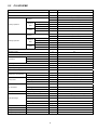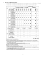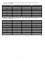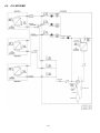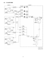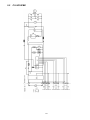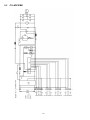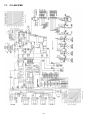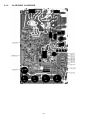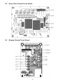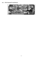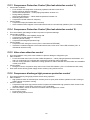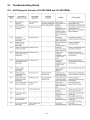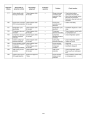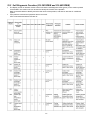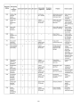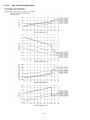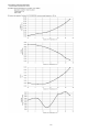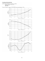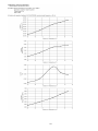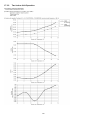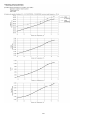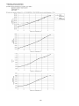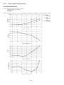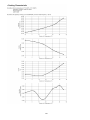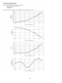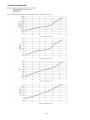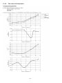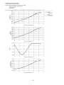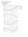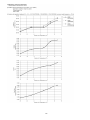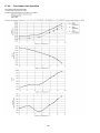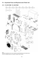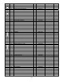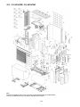
1
Order No: PAPAMY1301048CE Air Conditioner Outdoor Unit CU-2E15PBE CU-2E18PBE CU-3E18PBE CU-4E23PBE Destination Europe Please file and use this manual together with the service manual for Model No. CS-ME5PKE CS-E7PKEW CS-E9PKEW CS-E12PKEW CS-E15PKEW CS-E18PKEW CS-E21PKEW CS-XE7PKEW CS-XE9PKEW CS-XE12PKEW CS-XE15PKEW CS-XE18PKEW CS-XE21PKEW CS-ME9PD3EA CS-ME12PD3EA CS-ME18PD3EA CS-ME9PB4EA CS-ME12PB4EA CS-ME18PB4EA CS-ME21PB4EA CS-E9GFEW CS-E12GFEW CS-E18GFEW CS-E9GFEW-2 CS-E12GFEW-2 CS-E18GFEW-2, Order No. PAPAMY1301090CE PAPAMY1212045CE PAPAMY1301096CE PAPAMY1301095CE RAC0704001C2 MAC0804027A2 WARNING This service information is designed for experienced repair technicians only and is not designed for use by the general public. It does not contain warnings or cautions to advise non-technical individuals of potential dangers in attempting to service a product. Products powered by electricity should be serviced or repaired only by experienced professional technicians. Any attempt to service or repair the product or products dealt with in this service information by anyone else could result in serious injury or death. PRECAUTION OF LOW TEMPERATURE In order to avoid frostbite, be assured of no refrigerant leakage during the installation or repairing of refrigerant circuit. © Panasonic Corporation 2013 TABLE OF CONTENTS PAGE PAGE 1. Safety Precautions .............................................3 13.4 2. Specifications .....................................................5 13.5 13.6 13.7 2.1 2.2 2.3 2.4 CU-2E15PBE................................................5 CU-2E18PBE................................................7 CU-3E18PBE................................................9 CU-4E23PBE..............................................11 13.8 13.9 3. Dimensions .......................................................18 3.1 3.2 13.10 13.11 13.12 CU-2E15PBE CU-2E18PBE .....................18 CU-3E18PBE CU-4E23PBE .....................18 4. Refrigeration Cycle Diagram ...........................19 CU-2E15PBE CU-2E18PBE .....................19 CU-3E18PBE..............................................20 CU-4E23PBE..............................................21 13.13 5. Block Diagram ..................................................22 13.15 13.16 4.1 4.2 4.3 5.1 5.2 5.3 13.14 CU-2E15PBE CU-2E18PBE .....................22 CU-3E18PBE..............................................23 CU-4E23PBE..............................................24 14. Servicing Mode .................................................56 6. Wiring Connection Diagram ............................25 6.1 6.2 6.3 14.1 14.2 CU-2E15PBE CU-2E18PBE .....................25 CU-3E18PBE..............................................26 CU-4E23PBE..............................................27 15.1 15.2 CU-2E15PBE CU-2E18PBE .....................28 CU-3E18PBE..............................................29 CU-4E23PBE..............................................30 16.1 Main Printed Circuit Board .........................31 Noise Filter Printed Circuit Board ...............33 Display Printed Circuit Board .....................33 CPU Printed Circuit Board ..........................34 16.2 17.1 CU-2E15PBE..............................................35 CU-2E18PBE..............................................36 CU-3E18PBE..............................................37 CU-4E23PBE..............................................38 17.2 17.3 10. Installation Instruction .....................................39 10.1 10.2 17.4 CU-2E15PBE CU-2E18PBE .....................39 CU-3E18PBE CU-4E23PBE .....................43 18.1 18.2 Cooling Operation.......................................48 Heating Operation ......................................49 Outdoor Quiet Cooling Operation Control ........................................................49 12. Simultaneous Operation Control ....................51 13. Protection Control ............................................52 13.1 13.2 13.3 Operation Characteristics (CU-2E15PBE) ...........................................68 Operation Characteristics (CU-2E18PBE) ...........................................72 Operation Characteristics (CU-3E18PBE) ...........................................76 Operation Characteristics (CU-4E23PBE) ...........................................88 18. Exploded View and Replacement Parts List .................................................................. 100 11. Operation Control .............................................48 11.1 11.2 11.3 Outdoor Unit Removal Procedure (CU-2E15PBE CU-2E18PBE) ...................64 Outdoor Unit Removal Procedure (CU-3E18PBE CU-4E23PBE) ...................65 17. Technical Data ..................................................68 9. Installation Information ....................................35 9.1 9.2 9.3 9.4 Self Diagnosis Function (CU-2E15PBE and CU-2E18PBE) .............59 Self Diagnosis Function (CU-3E18PBE and CU-4E23PBE) .............61 16. Disassembly and Assembly Instructions ......64 8. Printed Circuit Board .......................................31 8.1 8.2 8.3 8.4 CU-3E18PBE & CU-4E23PBE ...................56 CU-2E15PBE & CU-2E18PBE ...................58 15. Troubleshooting Guide ....................................59 7. Electronic Circuit Diagram ..............................28 7.1 7.2 7.3 Electronic Parts Temperature Rise Protection 2 (Cool)......................................52 Cooling overload control (Cool) ..................53 Heating overload control (Heat) .................53 Extreme Low Temperature Compressor low pressure protection control (Heat) ..............53 Deice Control ..............................................54 Time Delay Safety Control (Restart Control) .........................................54 30 seconds Force Operation ......................54 Total Current Control ..................................54 IPM (power transistor) Protection Control ........................................................54 Compressor Protection Control (Gas leak detection control 1) ....................55 Compressor Protection Control (Gas leak detection control 2) ....................55 Valve close detection control......................55 Compressor discharge high pressure protection control ........................................55 Freeze Prevention control (Cool) ...............52 Dew Prevention control (Cool) ...................52 Electronic Parts Temperature Rise Protection 1 (Cool)......................................52 2 CU-2E15PBE CU-2E18PBE .................. 100 CU-3E18PBE CU-4E23PBE .................. 103 1. Safety Precautions Read the following “SAFETY PRECAUTIONS” carefully before perform any servicing. Electrical work must be installed or serviced by a licensed electrician. Be sure to use the correct rating of the power plug and main circuit for the model installed. The caution items stated here must be followed because these important contents are related to safety. The meaning of each indication used is as below. Incorrect installation or servicing due to ignoring of the instruction will cause harm or damage, and the seriousness is classified by the following indications. WARNING This indication shows the possibility of causing death or serious injury. CAUTION This indication shows the possibility of causing injury or damage to properties. The items to be followed are classified by the symbols: This symbol denotes item that is PROHIBITED from doing. Carry out test run to confirm that no abnormality occurs after the servicing. Then, explain to user the operation, care and maintenance as stated in instructions. Please remind the customer to keep the operating instructions for future reference. WARNING 1. Do not modify the machine, part, material during repairing service. 2. If wiring unit is supplied as repairing part, do not repair or connect the wire even only partial wire break. Exchange the whole wiring unit. 3. Do not wrench the fasten terminal. Pull it out or insert it straightly. 4. Engage dealer or specialist for installation and servicing. If installation or servicing done by the user is defective, it will cause water leakage, electrical shock or fire. 5. Install according to this installation instructions strictly. If installation is defective, it will cause water leakage, electric shock or fire. 6. Use the attached accessories parts and specified parts for installation and servicing. Otherwise, it will cause the set to fall, water leakage, fire or electrical shock. 7. Install at a strong and firm location which is able to withstand the set’s weight. If the strength is not enough or installation is not properly done, the set will drop and cause injury. 8. For electrical work, follow the local national wiring standard, regulation and the installation instruction. An independent circuit and single outlet must be used. If electrical circuit capacity is not enough or defect found in electrical work, it will cause electrical shock or fire. 9. This equipment is strongly recommended to install with Earth Leakage Circuit Breaker (ELCB) or Residual Current Device (RCD). Otherwise, it may cause electrical shock and fire in case equipment breakdown or insulation breakdown. 10. Do not use joint cable for indoor/outdoor connection cable. Use the specified indoor/outdoor connection cable, refer to Installation Instruction CONNECT THE CABLE TO THE INDOOR UNIT and connect tightly for indoor/outdoor connection. Clamp the cable so that no external force will be acted on the terminal. If connecting or fixing is not perfect, it will cause heat up or fire at the connection. 11. Wire routing must be properly arranged so that control board cover is fixed properly. If control board cover is not fixed perfectly, it will cause heat-up or fire at the connection point of terminal, fire or electrical shock. 12. When install or relocate air conditioner, do not let any substance other than the specified refrigerant, eg. air etc. mix into refrigeration cycle (piping). (Mixing of air etc. will cause abnormal high pressure in refrigeration cycle and result in explosion, injury etc.). 13. Do not install outdoor unit near handrail of veranda. When installing air-conditioner unit at veranda of high rise building, child may climb up to outdoor unit and cross over the handrail and causing accident. 14. This equipment must be properly earthed. Earth line must not be connected to gas pipe, water pipe, earth of lightning rod and telephone. Otherwise, it may cause electric shock in case equipment breakdown or insulation breakdown. 15. Keep away from small children, the thin film may cling to nose and mouth and prevent breathing. 16. Do not use unspecified cord, modified cord, joint cord or extension cord for power supply cord. Do not share the single outlet with other electrical appliances. Poor contact, poor insulation or over current will cause electrical shock or fire. 17. Tighten the flare nut with torque wrench according to specified method. If the flare nut is over-tightened, after a long period, the flare may break and cause refrigerant gas leakage. 3 18. For R410A models, when connecting the piping, do not use any existing (R22) pipes and flare nuts. Using such same may cause abnormally high pressure in the refrigeration cycle (piping), and possibly result in explosion and injury. Use only R410A materials. Thickness of copper pipes used with R410A must be more than 0.8mm. Never use copper pipes thinner than 0.8mm. It is desirable that the amount of residual oil is less than 40 mg/10m. 19. During installation, install the refrigerant piping properly before run the compressor. (Operation of compressor without fixing refrigeration piping and valves at opened condition will cause suck-in of air, abnormal high pressure in refrigeration cycle and result in explosion, injury etc.). 20. During pump down operation, stop the compressor before remove the refrigeration piping. (Removal of refrigeration piping while compressor is operating and valves are opened condition will cause suck-in of air, abnormal high pressure in refrigeration cycle and result in explosion, injury etc.). 21. After completion of installation or service, confirm there is no leakage or refrigerant gas. It may generate toxic gas when the refrigerant contacts with fire. 22. Ventilate if there is refrigerant gas leakage during operation. It may cause toxic gas when refrigerant contacts with fire. 23. Do not insert your fingers or other objects into the unit, high speed rotating fan may cause injury. 24. Must not use other parts except original parts described in catalog and manual. 25. Using of refrigerant other than the specified type may cause product damage, burst and injury etc. CAUTION 1. Do not install the unit at place where leakage of flammable gas may occur. In case gas leaks and accumulates at surrounding of the unit, it may cause fire. 2. Carry out drainage piping as mentioned in installation instructions. If drainage is not perfect, water may enter the room and damage the furniture. 3. Tighten the flare nut with torque wrench according to specified method. If the flare nut is over-tightened, after a long period, the flare may break and cause refrigerant gas leakage. 4. Do not touch outdoor unit air inlet and aluminium fin. It may cause injury. 5. Select an installation location which is easy for maintenance. 6. Pb free solder has a higher melting point than standard solder; typically the melting point is 50°F – 70°F (30°C – 40°C) higher. Please use a high temperature solder iron. In case of the soldering iron with temperature control, please set it to 700 ± 20°F (370 ± 10°C). Pb free solder will tend to splash when heated too high (about 1100°F / 600°C). 7. Power supply connection to the room air conditioner. 2 2 Use power supply cord 3 x 1.5 mm (CU-2E15***, CU-2E18***), 3 x 2.5 mm (CU-3E18***, CU-4E23***) type designation 60245 IEC 57 (CU-2E15***, CU-2E18***), 245 IEC 57 (CU-3E18***, CU-4E23***) or heavier cord. Connect the power supply cord of the air conditioner to the mains using one of the following method. Power supply point should be in easily accessible place for power disconnection in case of emergency. In some countries, permanent connection of this air conditioner to the power supply is prohibited. i. Power supply connection to the receptacle using power plug. Use an approved 15/16A (CU-2E15***, CU-2E18), 16A (CU-3E18***), 20A (CU-4E23***) power plug with earth pin for the connection to the socket. ii. Power supply connection to a circuit breaker for the permanent connection. Use an approved 16A (CU-2E15***, CU-2E18, CU-3E18***), 20A (CU-4E23***) circuit breaker for the permanent connection. It must be a double pole switch with a minimum 3.0 mm contact gap. 8. Do not release refrigerant during piping work for installation, servicing, reinstallation and during repairing a refrigerant parts. Take care of the liquid refrigerant, it may cause frostbite. 9. Installation or servicing work: It may need two people to carry out the installation or servicing work. 10. Do not install this appliance in a laundry room or other location where water may drip from the ceiling, etc. 11. Do not sit or step on the unit, you may fall down accidentally. 12. Do not touch the sharp aluminum fins or edges of metal parts. If you are required to handle sharp parts during installation or servicing, please wear hand glove. Sharp parts may cause injury. 4 2. Specifications 2.1 CU-2E15PBE Item Unit Indoor Unit Combination 2.0kW + 2.5kW Power Source 1 Phase, 230V, 50Hz (Power supply from outdoor unit) Capacity kW 4.5 (1.5 ~ 5.2) BTU/h 15300 (5120 ~ 17700) Running Current Cooling Operation Electrical Data A 5.75 kW 1.23 (0.25 ~ 1.52) W/W 3.66 (6.00 ~ 3.42) dB-A (H/L) 47 / - Power Input EER Noise Sound Pressure Level Sound Power Level dB (H/L) 62 / - kW 5.4 (1.1 ~ 7.0) BTU/h 18400 (3750 ~ 23900) Capacity Running Current Heating Operation OUTDOOR UNIT Electrical Data A 5.20 kW 1.17 (0.21 ~ 1.67) W/W 4.62 (5.24 ~ 4.19) dB-A (H/L) 49 / - Power Input COP Noise Sound Pressure Level dB (H/L) 64 / - Maximum Current Sound Power Level A 12.0 Starting Current A 5.75 Circuit Breaker Capacity Dimension A 15 Height mm 619 Width mm 824 (+70) Depth mm 299 Net Weight kg Connection Cable 39 3 + 1 (Earth) ø1.5 mm Pipe Length Range (1 room) m 3 ~ 20 Maximum Pipe Length (Total Room) m 30 Liquid Side mm (inch) 6.35 (1/4) Gas Side mm (inch) 9.52 (3/8) Refrigerant Pipe Diameter Type Compressor Hermetic Motor / Rotary Motor Type Brushless (6-poles) Rated Output W Type Air Circulation DC Motor (8-poles) High (Cooling / Heating) W 40 RPM 800 / 930 Type Plate fin configuration forced draft type Tube Material Heat Exchanger Copper Fin Material Aluminum (Pre Coat) Row / Stage 2 / 28 FPI Air Volume 900 Propeller Fan Motor Type Rated Output Fan Speed 2 17 3 High (Cooling / Heating) m /min Refrigerant Control Device 32.7 / 36.9 Expansion Valve Refrigerant Oil RB68A / Freol Alpha68M Refrigerant (R410A) g 5 1.40k Item Cooling Indoor Operation Range Heating Cooling Outdoor Operation Range Heating Unit Wet Bulb Maximum °C 32 23 Minimum °C 16 11 Maximum °C 30 — Minimum °C 16 — Maximum °C 46 26 Minimum °C -10 — Maximum °C 24 18 Minimum °C -15 -16 Note OUTDOOR UNIT Dry Bulb Specifications are subject to change without notice for further improvement. 6 2.2 CU-2E18PBE Item Unit Indoor Unit Combination 2.0kW + 3.2kW Power Source 1 Phase, 230V, 50Hz (Power supply from outdoor unit) Capacity kW 5.2 (1.5 ~ 5.4) BTU/h 17700 (5120 ~ 18400) A 7.10 Running Current Cooling Operation Electrical Data Power Input kW 1.52 (0.25 ~ 1.58) W/W 3.42 (6.00 ~ 3.42) dB-A (H/L) 49 / - dB (H/L) 64 / - EER Noise Sound Pressure Level Sound Power Level Capacity kW 5.6 (1.1 ~ 7.2) BTU/h 19100 (3750 ~ 24600) A 5.35 kW 1.21 (0.21 ~ 1.70) Running Current Heating Operation OUTDOOR UNIT Electrical Data Power Input COP W/W 4.63 (5.24 ~ 4.24) dB-A (H/L) 51 / - dB (H/L) 66 / - Maximum Current A 12.0 Starting Current A 7.1 Circuit Breaker Capacity A 15 Height mm 619 Width mm 824 (+70) Depth mm 299 kg 39 Noise Dimension Sound Pressure Level Sound Power Level Net Weight Connection Cable 3 + 1 (Earth) ø1.5 mm Pipe Length Range (1 room) m 3 ~ 20 Maximum Pipe Length (Total Room) m 30 Liquid Side mm (inch) 6.35 (1/4) Gas Side mm (inch) 9.52 (3/8) Refrigerant Pipe Diameter Type Compressor Hermetic Motor / Rotary Motor Type Brushless (6-poles) Rated Output W Type Air Circulation Motor Type DC Motor (8-poles) W High (Cooling / Heating) RPM Type Copper Fin Material Aluminum (Pre Coat) Row / Stage 2 / 28 FPI Air Volume 40 900 / 1000 Plate fin configuration forced draft type Tube Material Heat Exchanger 900 Propeller Fan Rated Output Fan Speed 2 17 3 High (Cooling / Heating) m /min Refrigerant Control Device 36.9 / 41.1 Expansion Valve Refrigerant Oil RB68A / Freol Alpha68M Refrigerant (R410A) g 7 1.40k Item Cooling Indoor Operation Range Heating Cooling Outdoor Operation Range Heating Unit Wet Bulb Maximum °C 32 23 Minimum °C 16 11 Maximum °C 30 — Minimum °C 16 — Maximum °C 46 26 Minimum °C -10 — Maximum °C 24 18 Minimum °C -15 -16 Note OUTDOOR UNIT Dry Bulb Specifications are subject to change without notice for further improvement. 8 2.3 CU-3E18PBE Item Unit Indoor Unit Combination 1.6kW + 1.6kW + 2.0kW Power Source 1 Phase, 230V, 50Hz (Power supply from outdoor unit) Capacity kW 5.2 (1.8 ~ 7.3) BTU/h 17700 (6140 ~ 24900) A 5.3 Running Current Cooling Operation Electrical Data Power Input kW 1.20 (0.36 ~ 2.18) W/W 4.33 (5.00 ~ 3.35) dB-A (H/L) 46 / - dB (H/L) 60 / - EER Noise Sound Pressure Level Sound Power Level Capacity kW 6.8 (1.6 ~ 8.3) BTU/h 23200 (5460 ~ 28300) A 6.7 kW 1.45 (0.32 ~ 2.11) Running Current Heating Operation OUTDOOR UNIT Electrical Data Power Input COP W/W 4.69 (5.00 ~ 3.93) dB-A (H/L) 47 / - dB (H/L) 61 / - Maximum Current A 15.2 Starting Current A 6.7 Circuit Breaker Capacity A 16 Height mm 795 Width mm 875 (+95) Depth mm 320 kg 71 Noise Dimension Sound Pressure Level Sound Power Level Net Weight Connection Cable 3 + 1 (Earth) ø1.5 mm Pipe Length Range (1 room) m 3 ~ 25 Maximum Pipe Length (Total Room) m 50 Liquid Side mm (inch) 6.35 (1/4) Gas Side mm (inch) 9.52 (3/8) Refrigerant Pipe Diameter Type Compressor Hermetic Motor / Rotary Motor Type Brushless (4-poles) Rated Output W Type Air Circulation Motor Type DC Motor (8-poles) High (Cooling / Heating) W 60 RPM 580 / 580 Type Plate fin configuration forced draft type Tube Material Heat Exchanger Copper Fin Material Aluminum (Pre Coat) Row / Stage 2 / 36 FPI Air Volume 1.30k Propeller Fan Rated Output Fan Speed 2 19 3 High m /min Refrigerant Control Device 41.7 Expansion Valve Refrigerant Oil FV50S Refrigerant (R410A) g 9 2.64k Item Cooling Indoor Operation Range Heating Cooling Outdoor Operation Range Heating Unit Wet Bulb Maximum °C 32 23 Minimum °C 16 11 Maximum °C 30 — Minimum °C 16 — Maximum °C 46 26 Minimum °C -10 — Maximum °C 24 18 Minimum °C -15 -16 Note OUTDOOR UNIT Dry Bulb Specifications are subject to change without notice for further improvement. 10 2.4 CU-4E23PBE Item Unit Indoor Unit Combination 1.6kW + 1.6kW + 1.6kW + 2.0kW Power Source 1 Phase, 230V, 50Hz (Power supply from outdoor unit) Capacity kW 6.8 (1.9 ~ 8.8) BTU/h 23200 (6480 ~ 30000) A 7.5 Running Current Cooling Operation Electrical Data Power Input kW 1.68 (0.34 ~ 2.47) W/W 4.05 (5.59 ~ 3.56) dB-A (H/L) 48 / - dB (H/L) 62 / - EER Noise Sound Pressure Level Sound Power Level Capacity kW 8.5 (3.0 ~ 10.6) BTU/h 29000 (10200 ~ 36100) A 8.8 kW 1.90 (0.58 ~ 2.60) Running Current Heating Operation OUTDOOR UNIT Electrical Data Power Input COP W/W 4.47 (5.17 ~ 4.08) dB-A (H/L) 49 / - dB (H/L) 63 / - Maximum Current A 15.6 Starting Current A 8.8 Circuit Breaker Capacity A 20 Height mm 795 Width mm 875 (+95) Depth mm 320 kg 72 Noise Dimension Sound Pressure Level Sound Power Level Net Weight Connection Cable 3 + 1 (Earth) ø1.5 mm 2 Pipe Length Range (1 room) m 3 ~ 25 Maximum Pipe Length (Total Room) m 60 Liquid Side mm (inch) 6.35 (1/4) Gas Side mm (inch) 9.52 (3/8) (E21:12.7(1/2)) Refrigerant Pipe Diameter Type Compressor Hermetic Motor / Rotary Motor Type Brushless (4-poles) Rated Output W Type Air Circulation Propeller Fan Motor Type DC Motor (8-poles) Rated Output Fan Speed High (Cooling / Heating) W 60 RPM 600 / 620 Type Plate fin configuration forced draft type Tube Material Heat Exchanger Copper Fin Material Aluminum (Pre Coat) Row / Stage 2 / 36 FPI Air Volume 1.30k High (Cooling / Heating) 19 3 m /min Refrigerant Control Device 42.5 / 44.1 Expansion Valve Refrigerant Oil FV50S Refrigerant (R410A) g 11 2.64k Item Cooling Indoor Operation Range Heating Cooling Outdoor Operation Range Heating Unit Wet Bulb Maximum °C 32 23 Minimum °C 16 11 Maximum °C 30 — Minimum °C 16 — Maximum °C 46 26 Minimum °C -10 — Maximum °C 24 18 Minimum °C -15 -16 Note OUTDOOR UNIT Dry Bulb Specifications are subject to change without notice for further improvement. 12 Multi Split Combination Possibility: o A single outdoor unit enables air conditioning of up to two separate rooms for CU-2E15PBE, CU-2E18PBE. o A single outdoor unit enables air conditioning of up to three separate rooms for CU-3E18PBE. o A single outdoor unit enables air conditioning of up to four separate rooms for CU-4E23PBE. 13 Indoor Unit : CS-ME5PKE, CS-E7/9/12PKEW, CS-E9/12GFEW, CS-ME9/12PB4EA, CS-ME9/12PD3EA Outdoor Unit : CU-2E15PBE 2 Room Indoor Unit Capacity (kW) 16 + 16 16 + 20 16 + 25 16 + 28 16 + 32 20 + 20 20 + 25 20 + 28 20 + 32 25 + 25 25 + 28 28 + 28 1 Room Total Indoor Capacity (kW) 32 36 41 44 48 40 45 48 52 50 53 56 Indoor Unit Capacity (kW) 16 20 25 28 32 Total Indoor Capacity (kW) 16 20 25 28 32 Indoor Unit : CS-ME5PKE, CS-E7/9/12PKEW, CS-E9/12GFEW, CS-ME9/12PB4EA, CS-ME9/12PD3EA Outdoor Unit : CU-2E18PBE 2 Room Indoor Unit Capacity (kW) 16 + 16 16 + 20 16 + 25 16 + 28 16 + 32 20 + 20 20 + 25 20 + 28 20 + 32 25 + 25 25 + 28 25 + 32 28 + 28 28 + 32 32 + 32 1 Room Total Indoor Capacity (kW) 32 36 41 44 48 40 45 48 52 50 53 57 56 60 64 Indoor Unit Capacity (kW) 16 20 25 28 32 14 Total Indoor Capacity (kW) 16 20 25 28 32 Indoor Unit : CS-ME5PKE, CS-E7/9/12/15/18PKEW, CS-E9/12/18GFEW, CS-ME9/12/18PB4EA, CS-ME9/12/18PD3EA Outdoor Unit : CU-3E18PBE 3 Room 2 Room 1 Room Indoor Unit Capacity (kW) Total Indoor Capacity (kW) Indoor Unit Capacity (kW) Total Indoor Capacity (kW) 16 + 16 + 16 16 + 16 + 20 16 + 16 + 25 16 + 16 + 28 16 + 16 + 32 16 + 16 + 40 16 + 16 + 50 16 + 20 + 20 16 + 20 + 25 16 + 20 + 28 16 + 20 + 32 16 + 20 + 40 16 + 20 + 50 16 + 25 + 25 16 + 25 + 28 16 + 25 + 32 16 + 25 + 40 16 + 28 + 28 16 + 28 + 32 16 + 28 + 40 16 + 32 + 32 16 + 32 + 40 20 + 20 + 20 20 + 20 + 25 20 + 20 + 28 20 + 20 + 32 20 + 20 + 40 20 + 20 + 50 20 + 25 + 25 20 + 25 + 28 20 + 25 + 32 20 + 25 + 40 20 + 28 + 28 20 + 28 + 32 20 + 28 + 40 20 + 32 + 32 25 + 25 + 25 25 + 25 + 28 25 + 25 + 32 25 + 25 + 40 25 + 28 + 28 25 + 28 + 32 25 + 32 + 32 28 + 28 + 28 28 + 28 + 32 48 52 57 60 64 72 82 56 61 64 68 76 86 66 69 73 81 72 76 84 80 88 60 65 68 72 80 90 70 73 77 85 76 80 88 84 75 78 82 90 81 85 89 84 88 16 + 32 16 + 40 16 + 50 20 + 25 20 + 28 20 + 32 20 + 40 20 + 50 25 + 25 25 + 28 25 + 32 25 + 40 25 + 50 28 + 28 28 + 32 28 + 40 28 + 50 32 + 32 32 + 40 32 + 50 40 + 40 40 + 50 48 56 66 45 48 52 60 70 50 53 57 65 75 56 60 68 78 64 72 82 80 90 15 Indoor Unit Capacity Total Indoor Capacity (kW) (kW) 16 20 25 28 32 40 50 16 20 25 28 32 40 50 Indoor Unit : CS-ME5PKE, CS-E7/9/12/15/18/21PKEW, CS-E9/12/18GFEW, CS-ME9/12/18/21PB4EA, CS-ME9/12/18PD3EA Outdoor Unit : CU-4E23PBE 4 Room 3 Room 2 Room 1 Room Indoor Unit Capacity (kW) Total Indoor Capacity (kW) Indoor Unit Capacity (kW) Total Indoor Capacity (kW) Indoor Unit Capacity (kW) Total Indoor Capacity (kW) Indoor Unit Capacity (kW) Total Indoor Capacity (kW) 16 + 16 + 16 + 16 16 + 16 + 16 + 20 16 + 16 + 16 + 25 16 + 16 + 16 + 28 16 + 16 + 16 + 32 16 + 16 + 16 + 40 16 + 16 + 16 + 50 16 + 16 + 16 + 60 16 + 16 + 20 + 20 16 + 16 + 20 + 25 16 + 16 + 20 + 28 16 + 16 + 20 + 32 16 + 16 + 20 + 40 16 + 16 + 20 + 50 16 + 16 + 25 + 25 16 + 16 + 25 + 28 16 + 16 + 25 + 32 16 + 16 + 25 + 40 16 + 16 + 25 + 50 16 + 16 + 28 + 28 16 + 16 + 28 + 32 16 + 16 + 28 + 40 16 + 16 + 28 + 50 16 + 16 + 32 + 32 16 + 16 + 32 + 40 16 + 20 + 20 + 20 16 + 20 + 20 + 25 16 + 20 + 20 + 28 16 + 20 + 20 + 32 16 + 20 + 20 + 40 16 + 20 + 20 + 50 16 + 20 + 25 + 25 16 + 20 + 25 + 28 16 + 20 + 25 + 32 16 + 20 + 25 + 40 16 + 20 + 28 + 28 16 + 20 + 28 + 32 16 + 20 + 28 + 40 16 + 20 + 32 + 32 16 + 20 + 32 + 40 16 + 25 + 25 + 25 16 + 25 + 25 + 28 16 + 25 + 25 + 32 16 + 25 + 25 + 40 16 + 25 + 28 + 28 16 + 25 + 28 + 32 16 + 25 + 28 + 40 16 + 25 + 32 + 32 16 + 28 + 28 + 28 16 + 28 + 28 + 32 16 + 28 + 32 + 32 20 + 20 + 20 + 20 20 + 20 + 20 + 25 20 + 20 + 20 + 28 20 + 20 + 20 + 32 20 + 20 + 20 + 40 20 + 20 + 20 + 50 20 + 20 + 25 + 25 64 68 73 76 80 88 98 108 72 77 80 84 92 102 82 85 89 97 107 88 92 100 110 96 104 76 81 84 88 96 106 86 89 93 101 92 96 104 100 108 91 94 98 106 97 101 109 105 100 104 108 80 85 88 92 100 110 90 16 + 16 + 16 16 + 16 + 20 16 + 16 + 25 16 + 16 + 28 16 + 16 + 32 16 + 16 + 40 16 + 16 + 50 16 + 16 + 60 16 + 20 + 20 16 + 20 + 25 16 + 20 + 28 16 + 20 + 32 16 + 20 + 40 16 + 20 + 50 16 + 20 + 60 16 + 25 + 25 16 + 25 + 28 16 + 25 + 32 16 + 25 + 40 16 + 25 + 50 16 + 25 + 60 16 + 28 + 28 16 + 28 + 32 16 + 28 + 40 16 + 28 + 50 16 + 28 + 60 16 + 32 + 32 16 + 32 + 40 16 + 32 + 50 16 + 32 + 60 16 + 40 + 40 16 + 40 + 50 20 + 20 + 20 20 + 20 + 25 20 + 20 + 28 20 + 20 + 32 20 + 20 + 40 20 + 20 + 50 20 + 20 + 60 20 + 25 + 25 20 + 25 + 28 20 + 25 + 32 20 + 25 + 40 20 + 25 + 50 20 + 25 + 60 20 + 28 + 28 20 + 28 + 32 20 + 28 + 40 20 + 28 + 50 20 + 28 + 60 20 + 32 + 32 20 + 32 + 40 20 + 32 + 50 20 + 40 + 40 20 + 40 + 50 25 + 25 + 25 25 + 25 + 28 25 + 25 + 32 48 52 57 60 64 72 82 92 56 61 64 68 76 86 96 66 69 73 81 91 101 72 76 84 94 104 80 88 98 108 96 106 60 65 68 72 80 90 100 70 73 77 85 95 105 76 80 88 98 108 84 92 102 100 110 75 78 82 16 + 32 16 + 40 16 + 50 16 + 60 20 + 25 20 + 28 20 + 32 20 + 40 20 + 50 20 + 60 25 + 25 25 + 28 25 + 32 25 + 40 25 + 50 25 + 60 28 + 28 28 + 32 28 + 40 28 + 50 28 + 60 32 + 32 32 + 40 32 + 50 32 + 60 40 + 40 40 + 50 40 + 60 50 + 50 50 + 60 48 56 66 76 45 48 52 60 70 80 50 53 57 65 75 85 56 60 68 78 88 64 72 82 92 80 90 100 100 110 16 20 25 28 32 40 50 60 16 20 25 28 32 40 50 60 16 4 Room Indoor Unit Total Indoor Capacity (kW) Capacity (kW) 20 + 20 + 25 + 28 93 20 + 20 + 25 + 32 97 20 + 20 + 25 + 40 105 20 + 20 + 28 + 28 96 20 + 20 + 28 + 32 100 20 + 20 + 28 + 40 108 20 + 20 + 32 + 32 104 20 + 25 + 25 + 25 95 20 + 25 + 25 + 28 98 20 + 25 + 25 + 32 102 20 + 25 + 25 + 40 110 20 + 25 + 28 + 28 101 20 + 25 + 28 + 32 105 20 + 25 + 32 + 32 109 20 + 28 + 28 + 28 104 20 + 28 + 28 + 32 108 25 + 25 + 25 + 25 100 25 + 25 + 25 + 28 103 25 + 25 + 25 + 32 107 25 + 25 + 28 + 28 106 25 + 25 + 28 + 32 110 25 + 28 + 28 + 28 109 3 Room Indoor Unit Total Indoor Capacity (kW) Capacity (kW) 25 + 25 + 40 90 25 + 25 + 50 100 25 + 25 + 60 110 25 + 28 + 28 81 25 + 28 + 32 85 25 + 28 + 40 93 25 + 28 + 50 103 25 + 32 + 32 89 25 + 32 + 40 97 25 + 32 + 50 107 25 + 40 + 40 105 28 + 28 + 28 84 28 + 28 + 32 88 28 + 28 + 40 96 28 + 28 + 50 106 28 + 32 + 32 92 28 + 32 + 40 100 28 + 32 + 50 110 28 + 40 + 40 108 32 + 32 + 32 96 32 + 32 + 40 104 17 2 Room Indoor Unit Total Indoor Capacity (kW) Capacity (kW) 1 Room Indoor Unit Total Indoor Capacity (kW) Capacity (kW) 3. Dimensions 3.1 CU-2E15PBE CU-2E18PBE 3.2 CU-3E18PBE CU-4E23PBE 18 4. Refrigeration Cycle Diagram 4.1 CU-2E15PBE CU-2E18PBE 19 4.2 CU-3E18PBE 20 4.3 CU-4E23PBE 21 5. Block Diagram 5.1 CU-2E15PBE CU-2E18PBE 22 5.2 CU-3E18PBE 23 5.3 CU-4E23PBE 24 6. Wiring Connection Diagram 6.1 CU-2E15PBE CU-2E18PBE 25 6.2 CU-3E18PBE 26 6.3 CU-4E23PBE 27 7. Electronic Circuit Diagram 7.1 CU-2E15PBE CU-2E18PBE 28 7.2 CU-3E18PBE 29 7.3 CU-4E23PBE 30 8. Printed Circuit Board 8.1 8.1.1 Main Printed Circuit Board CU-2E15PBE CU-2E18PBE 31 8.1.2 CU-3E18PBE CU-4E23PBE 32 8.2 Noise Filter Printed Circuit Board 8.3 Display Printed Circuit Board 33 8.4 CPU Printed Circuit Board 34 9. Installation Information 9.1 CU-2E15PBE 9.1.1 Check Points 9.1.2 The Shapes of the 3-Way Valve Caps of the Outdoor Unit Have Been Changed Accompanying the changes in the shapes of the 3-way valve caps, the tightening method has also been changed. Firmly tighten the 3-way valve caps by hand, and then tighten them up by another 30 degrees or so (one-twelfth of a full turn) using a spanner or adjustable spanner. 35 9.2 CU-2E18PBE 9.2.1 Check Points 9.2.2 The Shapes of the 3-Way Valve Caps of the Outdoor Unit Have Been Changed Accompanying the changes in the shapes of the 3-way valve caps, the tightening method has also been changed. Firmly tighten the 3-way valve caps by hand, and then tighten them up by another 30 degrees or so (one-twelfth of a full turn) using a spanner or adjustable spanner. 36 9.3 9.3.1 CU-3E18PBE Check Points 37 9.4 9.4.1 CU-4E23PBE Check Points 38 10. Installation Instruction 10.1 CU-2E15PBE CU-2E18PBE 10.1.1 Select The Best Location If an awning is built over the unit to prevent direct sunlight or rain, be careful that heat radiation from the condenser is not obstructed. There should not be any animal or plant which could be affected by hot air discharged. Keep the spaces indicated by arrows from wall, ceiling, fence or other obstacles. Do not place any obstacles which may cause a short circuit of the discharged air. If piping length is over the common length, additional refrigerant should be added as shown in the table. Additional Std. Min. Max. total Max. gas charge Length Length Length Elevation amount (m) (m) (m) (m) (g/m) Gas Liquid 5 m / 3 m / 9.52 mm 6.35 mm indoor indoor 30 10 15 (3/8") (1/4") unit unit Piping size Note: (1) It is possible to extend the piping length of one unit up to 20 meters. However, the total piping length must not exceed 30 meters. (2) If the length exceeds 20 meters, refrigerant of 15g per meter must be added. 10.1.2 If a drain elbow is used, the unit should be placed on a stand which is taller than 3 cm. If the unit is used in an area where temperature falls below 0°C for 2 or 3 days in succession, it is recommended not to use a drain elbow, for the drain water freezes and the fan will not rotate. 10.1.3 Disposal Of Outdoor Unit Drain Water Install The Outdoor Unit After selecting the best location, start installation to Indoor/Outdoor Unit Installation Diagram. 1. Fix the unit on concrete or rigid frame firmly and horizontally by bolt nut (ø10 mm). 2. When installing at roof, please consider strong wind and earthquake. Please fasten the installation stand firmly with bolt or nails. Model A B C D 2E15***, 2E18*** 540 mm 160 mm 18.5 mm 330 mm 39 10.1.4 Connect the Piping Connecting The Piping To Indoor Unit Please make flare after inserting flare nut (locate at joint portion of tube assembly) onto the copper pipe. (In case of using long piping) Do not over tighten, over tightening may cause gas leakage. Piping size 6.35 mm (1/4") 9.52 mm (3/8") 12.7 mm (1/2") 15.88 mm (5/8") 19.05 mm (3/4") Connect the piping Align the center of piping and sufficiently tighten the flare nut with fingers. Further tighten the flare nut with torque wrench in specified torque as stated in the table. Torque [18 N•m (1.8 kgf.m)] [42 N•m (4.3 kgf.m)] [55 N•m (5.6 kgf.m)] [65 N•m (6.6 kgf.m)] [100 N•m (10.2 kgf.m)] Connecting The Piping To Outdoor Multi Decide piping length and then cut by using pipe cutter. Remove burrs from cut edge. Make flare after inserting the flare nut (locate at valve) onto the copper pipe. Align center of piping to valves and then tighten with torque wrench to the specified torque as stated in the table. CUTTING AND FLARING THE PIPING 1. Please cut using pipe cutter and then remove the burrs. 2. Remove the burrs by using reamer. If burrs is not removed, gas leakage may be caused. Turn the piping end down to avoid the metal powder entering the pipe. 3. Please make flare after inserting the flare nut onto the copper pipes. 10.1.5 Evacuation of the Equipment WHEN INSTALLING AN AIR CONDITIONER, BE SURE TO EVACUATE THE AIR INSIDE THE INDOOR UNIT AND PIPES in the following procedure. 1. Connect a charging hose with a push pin to the Low side of a charging set and the service port of the 3-way valve. o Be sure to connect the end of the charging hose with the push pin to the service port. 40 2. Connect the center hose of the charging set to a vacuum pump with check valve, or vacuum pump adaptor. 3. Turn on the power switch of the vacuum pump and make sure that the needle in the gauge moves from 0 cmHg (0 MPa) to -76 cmHg (-0.1 MPa). Then evacuate the air approximately 10 minutes. 4. Close the Low and High side valves of the charging set and turn off the vacuum pump. Make sure that the needle in the gauge does not move after approximately 5 minutes. Note: BE SURE TO FOLLOW THIS PROCEDURE IN ORDER TO AVOID REFRIGERANT GAS LEAKAGE. 5. Disconnect the charging hose from the vacuum pump and from the service port of the 3-way valve. 6. Tighten the service port caps of the 3-way valve at a torque of 18 N•m with a torque wrench. 7. Remove the valve caps of the both 3-way valves. Position both of the valves to “OPEN” using a hexagonal wrench (4 mm). 8. Mount valve caps onto the both 3-way valves. o Be sure to check for gas leakage. - 10.1.6 If gauge needle does not move from 0 cmHg (0 MPa) to -76 cmHg (-0.1 MPa), in step e above take the following measure: If the leak stops when the piping connections are tightened further, continue working from step e. If the leak does not stop when the connections are retightened, repair location of leak. Do not release refrigerant during piping work for installation and reinstallation. Take care of the liquid refrigerant, it may cause frostbite. Connect The Cable To The Outdoor Unit 1. Remove the control board cover (metal) from the unit by loosening two screws. 2. Cable connection to the power supply through isolating Devices (Disconnecting means). o Connect approved type polychloroprene sheathed power supply cord 3 x 1.5 mm2 type designation 60245 IEC 57 or heavier cord to the terminal board, and connect the others end of the cord to Isolating Devices (Disconnecting means) 3. Connection cable between indoor unit and outdoor unit shall be approved polychloroprene sheathed 4 x 1.5 mm2 flexible cord, type designation 60245 IEC 57 or heavier cord. 4. Connect the power supply cord and connecting cable between indoor unit and outdoor unit according to the diagram as shown. 5. Secure the power supply cord and connection cables onto the control board with the holder. 6. Attach the control board cover back to the original position with screw. 7. For wire stripping and connection requirement, refer to the diagram as shown. Note: Isolating Devices (Disconnecting means) should have minimum 3.0 mm contact gap. Earth wire shall be Yellow/Green (Y/G) in colour and longer than other AC wires for safety reason. 41 10.1.7 Piping Insulation 1. Please carry out insulation at pipe connection portion as mentioned in Indoor/Outdoor Unit Installation Diagram. Please wrap the insulated piping end to prevent water from going inside the piping. 2. If drain hose or connecting piping is in the room (where dew may form), please increase the insulation by using POLY-E FOAM with thickness 6mm or above. 42 10.2 CU-3E18PBE CU-4E23PBE 10.2.1 Select The Best Location If an awning is built over the unit to prevent direct sunlight or rain, be careful that heat radiation from the condenser is not obstructed. There should not be any animal or plant which could be affected by hot air discharged. Keep the spaces indicated by arrows from wall, ceiling, fence or other obstacles. Do not place any obstacles which may cause a short circuit of the discharged air. Refrigerant piping size Outdoor Unit CU-3E18*** CU-4E23*** Liquid - side ø 6.35 t0.8 ø 6.35 t0.8 Gas - side ø 9.52 t0.8 ø 9.52 t0.8 *(ø 12.7 t0.8) * In case of indoor is CS-E21***, CS-XE21***, CS-ME21***, then ø 12.7 t0.8 gas-pipe size must be used together with CZ-MA2P (pipe size expander) Outdoor Unit CU-3E18*** CU-4E23*** Equivalent length 30 m 30 m If total piping length of all indoor units exceed the equivalent length listed above, additional charge with 20g of refrigerant (R410A) for each additional meter of piping. Allowable piping length Outdoor Unit CU-3E18*** CU-4E23*** Allowable piping length of each indoor unit (min. ~ max.) 3 m ~ 25 m 3 m ~ 25 m Allowable total piping length of all indoor unit Height difference between indoor and outdoor unit Height difference between indoor unit 50 m or less 60 m or less Outdoor unit located on upper side 15 m or less 15 m or less Outdoor unit located otherwise 7.5 m or less 7.5 m or less Outdoor unit located on upper side 7.5 m or less 7.5 m or less Outdoor unit located otherwise 15 m or less 15 m or less 43 Outdoor Unit Installation Guidelines Where a wall or other obstacle is in the path of outdoor unit’s intake or exhaust airflow, follow the installation guidelines below. For any of the below installation patterns, the wall height on the exhaust side should be 1200mm or less. 10.2.2 After selecting the best location, start installation to Indoor/Outdoor Unit Installation Diagram. 1. Fix the unit on concrete or rigid frame firmly and horizontally by bolt nut (ø10 mm). 2. When installing at roof, please consider strong wind and earthquake. Please fasten the installation stand firmly with bolt or nails. 10.2.3 Install The Outdoor Unit Model A B C D CU-3E18*** CU-4E23*** 613 mm 131 mm 16 mm 360.5 mm Connect The Piping Remove the control board cover (resin) from the unit by loosening three screws. Do not over tighten, over tightening may cause gas leakage Connecting The Piping To Outdoor Unit Decide piping length and then cut by using pipe cutter. Remove burrs from cut edge. Make flare after inserting the flare nut (locate at valve) onto the copper pipe. Align center of piping to valves and then tighten with torque wrench to the specified torque as stated in the table. 44 Piping size Torque 1/4" [6.35 mm] [18 N•m (1.8 kgf.m)] 3/8" [9.52 mm] [42 N•m (4.3 kgf.m)] 1/2" [12.7 mm] [55 N•m (5.6 kgf.m)] 5/8" [15.88 mm] [65 N•m (6.6 kgf.m)] 3/4" [19.05 mm] [100 N•m (10.2 kgf.m)] CUTTING AND FLARING THE PIPING 1. Please cut using pipe cutter and then remove the burrs. 2. Remove the burrs by using reamer. If burrs is not removed, gas leakage may be caused. Turn the piping end down to avoid the metal powder entering the pipe. 3. Please make flare after inserting the flare nut onto the copper pipes. 10.2.4 Evacuation Of The Equipment WHEN INSTALLING AN AIR CONDITIONER, BE SURE TO EVACUATE THE AIR INSIDE THE INDOOR UNIT AND PIPES in the following procedure. 1. Connect a charging hose with a push pin to the Low side of a charging set and the service port of the gas side 3-way valve. o Be sure to connect the end of the charging hose with the push pin to the service port. 2. Connect the center hose of the charging set to a vacuum pump. 3. Turn on the power switch of the vacuum pump and make sure that the needle in the gauge moves from 0 cmHg (0 MPa) to -76 cmHg (-0.1 MPa). Then evacuate the air approximately ten minutes. 4. Close the Low side valve of the charging set and turn off the vacuum pump. Make sure that the needle in the gauge does not move after approximately five minutes. o Note : BE SURE TO TAKE THIS PROCEDURE IN ORDER TO AVOID REFRIGERANT GAS LEAKAGE. 5. Disconnect the charging hose from the vacuum pump and from the service port of the 3-way valve. 6. Tighten the service port caps of gas side 3-way valve at a torque of 18 N•m with a torque wrench. 7. Remove the valve caps of both of the gas side and liquid side 3-way valve. Position both of the valves to “OPEN” using a hexagonal wrench (4 mm). 8. Mount valve caps onto the gas side and liquid side of the 3-way valve. o Be sure to check for gas leakages. - If gauge needle does not move from 0 cmHg (0 MPa) to -76 cmHg (-0.1 MPa), in step e above take the following measure: If the leak stops when the piping connections are tightened further, continue working from step e. If the leak does not stop when the connections are retightened, repair location of leak. Do not release refrigerant during piping work for installation and reinstallation. Take care of the liquid refrigerant, it may cause frostbite. 45 10.2.5 Connect The Cable To The Outdoor Unit 1. Remove the control board cover metal from the unit by loosening two screws. 2. Cable connection to the power supply through isolating Devices (Disconnecting means). o Connect approved type polychloroprene sheathed power supply cord 3 x 2.5 mm2 245 IEC 57 type designation or heavier cord to the terminal board, and connect the others end of the cord to Isolating Devices (Disconnecting means). 3. Connecting cable between indoor unit and outdoor unit shall be approved polychloroprene sheathed 4 x 1.5 mm2 flexible cord, type designation 245 IEC 57 or heavier cord. 4. Connect the power supply cord and connecting cable between indoor unit and outdoor unit according to the diagram as shown. 5. For wire stripping and connection requirement, refer to the diagram below. 6. Secure the power supply cord and connecting cables onto the control board with the holder. 7. Attach the control board cover back to the original position with screw. This equipment must be properly earthed. Note: Isolating Devices (Disconnecting means) should have minimum 3.0 mm contact gap. Earth wire shall be Yellow/Green (Y/G) in colour and longer than other AC wires for safety reason. 46 10.2.6 Heat Insulation Use a material with good heat-resistant properties as the heat insulation for the pipes. Be sure to insulate both the gas-side and liquid-side pipes. If the pipes are not adequately insulated, condensation or water leakages may occur. 47 Liquid-side pipes Gas-side pipes Material shall withstand 120°C or higher 11. Operation Control 11.1 Cooling Operation 11.1.1 When cooling operation is enabled, based on outdoor ambient temperature, fan motor control will be adjusted according to figure below: 11.1.2 Annual Cooling control This control is to enable cooling operation when outdoor ambient temperature is low. Control start conditions: o Cooling operation is activated with compressor ON. o Outdoor ambient temperature is less than 15°C Control contents: o When the above conditions are fulfilled, based on outdoor pipe temperature, the outdoor fan motor will operate according to figure below: To improve the judgment accuracy during annual cooling control, outdoor ambient temperature sampling for 2 minutes will be activated every 35 minutes under designated fan speed. Control stop conditions: o When either one of the start conditions are not complied. 11.1.3 Outdoor fan control Cooling Powerful Operation 1 During cooling operation, this control is to concentrate outdoor unit capability to the powerful operation enabled indoor unit by temporary stop the capability supply to low load demand indoor units. Operation start condition: o Powerful operation ON for targeted indoor unit Operation content: o If other indoor units (where Powerful operation are OFF) achieve setting temperature continuously for 1 minute after received powerful command from indoor unit, then capability supply to other indoor units are stopped for minimum 3 minutes. Capability supply stop period follows powerful operation period. Operation stops when comply either one of the following conditions: o When other indoor units (where Powerful operation are OFF) is demand for capacity. o When the powerful operation is OFF for all indoor units. o When Quiet operation received from 1 indoor unit. o When protection control starts. 48 11.2 Heating Operation 11.2.1 When heating operation is enabled, based on outdoor ambient temperature, fan motor control will be adjusted according to figure below for Heating overload control: 11.2.2 Heating Room Temp Sampling Control To improve the judgment accuracy, indoor room temperature sampling starts when any indoor unit has stopped capability supplied (heating thermo-off) during heating operation with compressor ON, outdoor unit will send signal to all thermo-off indoor units to ON fan motor and get room temperature sample. To prevent discharge temperature drop at indoor units which is ON when sampling the room temperature of heating thermo-off units, the compressor frequency is increased accordingly. However, if indoor room temperature is much higher compare to remote control setting temperature, before thermo-off, sampling of corresponding indoor unit will be cancelled. 11.2.3 Outdoor fan control Powerful Operation 2 During cooling / heating operation, this control is to provide fast cooling / heating operation compare to normal operation. Operation start if all condition below are complied: o Powerful operation ON for indoor unit. o Not under Annual Cooling control. Operation content: o Outdoor fan speed will adjust automatically. o Compressor frequency will adjust automatically. Operation stop when comply either one of the follow conditions: o When the powerful operation is OFF for all indoor units. o When annual cooling control activated. 11.3 Outdoor Quiet Cooling Operation Control Purpose Provide quiet cooling operation when only 1 indoor in operation. Start Condition o Indoor fan speed is lower than Lo fan. o Only 1 operation indoor unit. o Not in any cooling overload zone. o Not during annual cooling o Not initial frequency operation. o Not during starting control. o Not during “Electronic part temperature rise protection by outdoor air & total current” o Not during “Electronic part temperature rise protection by total current” o Not during “IPM temperature rise prevention control” o During cool mode All conditions above are satisfied and function selection enable. 49 Control Contents Compressor frequency and outdoor fan speed maximum limit is set. Adjust accordingly. Cool/Quiet Compressor frequency Outdoor fan speed #30 Hz #400 rpm Cancel Condition o Indoor fan speed is equal or higher than Lo fan. o > 1 operation indoor unit. o In any cooling overload zone. o During annual cooling o Initial frequency operation. o During starting control. o During “Electronic part temperature rise protection by outdoor air & total current” o During “Electronic part temperature rise protection by total current” o During “IPM temperature rise prevention control” o Not during cool mode When any above is satisfied. 50 12. Simultaneous Operation Control Operation modes which can be selected using the remote control unit: o Automatic, Cooling, Dry, Heating and e-ion operation mode. Types of operation modes which can be performed simultaneously o Cooling operation and Cooling, Dry or e-ion operation. o Heating operation and Heating operation. Types of operation modes which cannot be performed simultaneously o During cooling operation, heating operation is impossible at another indoor unit in another room. o The priority is given to cooling operation if the cooling mode is selected first. In another room where heating mode is selected afterward, the POWER LED blinks to indicate the heating operation is in standby condition, where the fan is stopped hence no discharged air. o During heating operation, cooling operation is impossible at another indoor unit in another room. o The priority is given to heating operation if the heating mode is selected first. In another room where cooling mode is selected afterward, the POWER LED blinks to indicate the cooling operation is in standby condition, where the fan is stopped hence no discharged air. Operation mode priority control o The operation mode designated first by the indoor unit has priority. o If the priority indoor unit stops operation or initiates the fan operation, the priority is transferred to other indoor units. “Waiting” denotes the standby status in which the POWER LED blinks (ON for 2.5 seconds and OFF for 0.5 seconds) and the fan is stopped. In the e-ion mode, priority is transferred to a non-priority unit. Note C: Cooling operation mode D: Dry operation mode H: Heating operation mode E: e-ion operation mode 51 13. Protection Control 13.1 Freeze Prevention control (Cool) When received freeze prevention signal from indoor unit, the compressor frequency changes according to indoor heat exchanger temperature. When indoor unit request capability OFF due to freeze condition, immediately the capability supply to targeted indoor unit stops. 13.2 Dew Prevention control (Cool) When received dew prevention signal from indoor unit, which according to indoor intake temperature and indoor heat exchanger temperature the compressor frequency changes. 13.3 Electronic Parts Temperature Rise Protection 1 (Cool) This control prevents electronic parts temperature rise during cooling overload condition. Start conditions: o Outdoor ambient temperature is at protection region as shown in figure below: o Outdoor unit total current is above 5.5A (4E/3E), 5.0A (2E18/2E15) Control content o Outdoor fan speed is adjusted accordingly. Control stop condition o When outdoor ambient temperature is back to normal region. During this control, outdoor fan speed does not reduce for Quiet operation. 13.4 Electronic Parts Temperature Rise Protection 2 (Cool) This control prevents electronic parts temperature rise during cooling/dry operation. Start conditions: o Total current is at protection region as shown in figure below: Control content o Outdoor fan speed is adjusted accordingly. Control stop conditions o When total current is back to normal region. During this control, outdoor fan speed does not reduce for Quiet operation. 52 13.5 Cooling overload control (Cool) This control detect outdoor pipe temperature and perform the compressor frequency restriction during cooling operation. 13.6 Heating overload control (Heat) This control detect indoor pipe temperature and perform the compressor frequency restriction during heating operation. This control detect outdoor ambient temperature and perform the fan speed adjustment during heating operation. 13.7 Extreme Low Temperature Compressor low pressure protection control (Heat) This control is to prevent low pressure drops too low during extremely low outdoor ambient temperature to improve the compressor reliability. During heating operation, when outdoor ambient temperature is in Zone 1, this control will be activated. Compressor frequency restriction will be based on outdoor piping temperature. 53 13.8 Deice Control When outdoor pipe temperature and outdoor air temperature is low, deice operation starts where indoor fan motor and outdoor fan motor stop, indoor unit horizontal vane close and operation LED blink with compressor ON. 13.9 Time Delay Safety Control (Restart Control) The compressor will not restart within three minutes after compressor is stopped. This control is not applicable if the power supply reset or after deice condition. 13.10 30 seconds Force Operation Once the compressor starts operation, it will not stop its operation for 30 seconds in order to cycle back compressor oil. However, it can be stopped using remote control or Auto OFF/ON button at indoor unit. 13.11 Total Current Control By referring to table below, during normal (default) operation, the running current refer to Hi values and during Power Save Mode, the running current refer to Lo values. (not applicable for 2E18/2E15) When the outdoor unit total running current (AC) exceeds X value, compressor frequency will decrease. If the running current does not exceed X value for 5 seconds, compressor frequency will increase. However, if total outdoor unit running current exceeds Y value, compressor will be stopped immediately for 3 minutes. CU-4E23PBE Operation Mode Cooling/Soft Dry (A) Cooling/Soft Dry (B) Heating X (A) CU-3E18PBE Y (A) X (A) CU-2E18PBE CU-2E15PBE Y (A) X (A) Y (A) X (A) Y (A) Hi 14.0 17.5 14.0 17.5 10.12 12.54 10.12 12.54 Lo 9.8 17.5 9.8 17.5 - - - - Hi 14.0 17.5 14.0 17.5 8.79 12.54 8.79 12.54 Lo 9.8 17.5 9.8 17.5 - - - - Hi 14.0 17.5 14.0 17.5 11.04 12.54 11.04 12.54 Lo 9.8 17.5 9.8 17.5 - - - - 13.12 IPM (power transistor) Protection Control Overheating Prevention Control o If IPM temperature rises to 80°C, outdoor fan speed will be increased. o When the IPM temperature rises to 95°C, compressor operation will stop immediately. o Compressor operation restarts when temperature decreases to 90°C. o If IPM temperature detected less than -30°C, IPM is judged as open circuit (“F96” is indicated). DC peak current control o When IPM DC current exceeds set value of 30.0 ± 3.0 A, the compressor will stop. o If the DC peak current detected within 30 seconds after operation starts, compressor will restart after 1 minute. o If the DC peak current detected 30 seconds or more after operation starts, compressor will restart after 2 minutes. o Within 30 seconds after compressor restarts, if the DC peak current is exceeded set value continuously for 7 times, all indoor and outdoor relays will be cut off (“F99” is indicated). Error reset can be done by power supply reset. 54 13.13 Compressor Protection Control (Gas leak detection control 1) Control start conditions o For 5 minutes, the compressor continuously operates and total current is low. o During Cooling or Soft Dry operation: Indoor intake temperature — indoor piping temperature is below 4°C. o During Heating operation: Indoor pipe temperature — indoor intake temperature is below 3°C. o Not during deice control. o Compressor ON with maximum frequency. Control content o Compressor stops (and restart after 3 minutes) o If the conditions above happen 4 times within 60 minutes, the unit will stop operation (“F91” is indicated). 13.14 Compressor Protection Control (Gas leak detection control 2) This control detect gas leakage condition to prevent compressor damage. Control start condition o All connected indoor units capability supply ON. o Compressor ON with maximum frequency. o Not during annual cooling. o Compressor discharge temperature high. Control content o Compressor OFF during this control (“F91” is memorized in EEPROM) o If the above conditions happen 2 times within 60 minutes, indoor units’ Timer LED will blinks (“F91” is indicated at all indoor units) 13.15 Valve close detection control This control detects 3-way valve close condition to prevent damage to refrigerant cycle. Start conditions: o For all connected indoor units, if Indoor intake temperature — indoor piping temperature are between -2°C and 2°C continuously for 5 minutes after compressor ON at first cooling operation. o The first cooling operation is defined as cooling operation is ON for less than 8 minutes after new installation or after pump down. Control content o During this control, compressor stop, indoor units’ Timer LED will blink. (“F91” is indicated at indoor units) Error reset can be done by power supply reset or reset by using remote control. 13.16 Compressor discharge high pressure protection control This control protect by using high pressure switch during operation. Start conditions o High pressure switch is activated (from normally close to open) when outdoor operation mode is cooling or heating during compressor running. Control 1 content o Compressor stop when high pressure switch is opened and restart after high pressure switch closed. If this condition happen 4 times within 30 minutes, “F94” is indicated. o After 30 minutes, counter is reset if this condition does not happen for 4 times. Control 1 stop conditions o Power supply reset o Reset by using remote control 55 14. Servicing Mode 14.1 CU-3E18PBE & CU-4E23PBE 14.1.1 Pump down operation (SW1) Operate the pump down process according to the following procedure o Confirm the valve on the liquid side and gas side are open. o Press PUMP DOWN button (SW1) on the Service PCB inside the outdoor unit for more than 5 seconds. Pump down (cooling) operation is performed for 15 minutes. o Set the liquid side 3 way valve to close position and wait until the pressure gauge indicates 0.01MPa (0.1kg/cm2G). o Immediate set the gas side valve to close position and then press the PUMP DOWN button (SW1) to stop the pump down operation. NOTE: Pump down operation will stop automatically after 15 minutes if PUMP DOWN switch (SW1) is not pressed again. Pump down operation is not started within 3 minutes after compressor is stopped. LED 2 3 4 5 Message Pump down operation in progress Status 3 minutes before operation end 2 minutes before operation end 1 minute before operation end Pump down operation end : Blinking 14.1.2 Test Run Operation Test operation can be carried out using TEST OPERATION button (SW2) on the Service PCB inside the outdoor unit. For Cooling test, press the TEST OPERATION button (SW2) for 5 seconds or more but less than 10 seconds, LED1 and LED 2 will illuminate when shift into cooling test operation. For Heating test, press the TEST OPERATION button (SW2) for more than 10 seconds, LED 1 and LED 3 will illuminate when shift into heating test operation. Press the TEST OPERATION button (SW2) again to cancel test operation. 56 14.1.3 Wiring Error Check The unit capable to correct the wiring error automatically by following procedures. o Confirm the valve on the liquid side and gas side is open. o Press WIRING CHECK button (SW3) on the Service PCB inside the outdoor unit for more than 10 seconds to start wiring check operation. o Wiring check process will complete in approximately 20 - 25 minutes. However, wiring check operation will not start within 3 minutes after compressor is stopped. When outdoor air temperature is less than 5°C or unit has abnormality, wiring check will not start. (See NOTE 2) The LED 2 to LED 6 in Service PCB inside the outdoor unit indicate the possibility of the correction as shown in the table below: LED 2 3 4 5 6 Room A B C D - Status All flashing Automatic correction impossible LED2, 4, 6 and LED 3, 5 Wiring check in progress alternatively flashing Flashing one after Automatic correction completed another Other than above Message Unit has abnormality (NOTE 4) If automatic correct is impossible, check the indoor unit wiring and piping manually. NOTE: 1. For two rooms connection, LED 4 and 5 are not illuminated and for three rooms connections, LED 5 is not illuminated after wiring operation complete. 2. If the outdoor air temperature is less than 5°C or unit has abnormality, wiring operation will not start. 3. After wiring check operation is complete, LED indication will illuminated until normal operation starts. 4. Follow the product diagnosis procedure. 5. When LED 1 only illuminate, indicates that outdoor unit is operating normally. 14.1.4 Power Save Mode can be enabled by pushing POWER SAVE switch (SW4) to ON before power supply ON. When Power Save Mode is ON, the unit can be operate at lower running current where the breaker capacity not achieve the requirement. 14.1.5 Mode priority function Mode priority function can be enabled by pushing MODE PRIORITY switch (SW5) to ON before power supply ON. When Mode Priority Function is ON, the mode priority is given to higher capacity indoor units. 14.1.6 Power Save Mode Cooling only function The unit capable to limit the operation mode to Cooling Mode only (Heating mode disabled) by cutting JP1 (COOL ONLY) before power supply ON. This function prevent wrong operation during the unit installed in server room. This function could be disabled again by short the JP1 (COOL ONLY) before power supply ON. 57 14.2 CU-2E15PBE & CU-2E18PBE 14.2.1 Pump down operation Operate the pump down process according to the following procedure o Confirm the valve on the liquid side and gas side are open. o Short the CN-PUMP button on the Service PCB inside the outdoor unit for more than 5 seconds. Pump down (cooling) operation is performed for 15 minutes. o Set the liquid side 3 way valve to close position and wait until the pressure gauge indicates 0.01MPa (0.1kg/cm2G). o Immediate set the gas side valve to close position and then Short the CN-PUMP button to stop the pump down operation. NOTE: Pump down operation will stop automatically after 15 minutes if CN-PUMP button is not shorted again. Pump down operation is not started within 3 minutes after compressor is stopped. 14.2.2 Cooling only function The unit capable to limit the operation mode to Cooling Mode only (Heating mode disabled) by switch to ON (SW-COOLING) at outdoor main PCB before power supply ON. This function prevent wrong operation during the unit installed in server room. This function could be disabled again by switch to OFF (SW-COOLING) at outdoor main PCB before power supply ON. 58 15. Troubleshooting Guide 15.1 Self Diagnosis Function (CU-2E15PBE and CU-2E18PBE) 59 60 15.2 Self Diagnosis Function (CU-3E18PBE and CU-4E23PBE) The display screen of wireless remote control unit and the self-diagnosis LEDs (green) on the outdoor printed circuit board in the outdoor unit can be used to identify the location of the problem. Refer to the table below to identify and solve the cause of the problem, and then re-start the air conditioner system. If the problem is solved and operation returns to normal. LED 1 illuminates and others LED are off. 61 62 63 16. Disassembly and Assembly Instructions WARNING High voltages are generated in the electrical parts area by the capacitor. Ensure that the capacitor has discharged sufficiently before proceeding with repair work. Failure to heed this caution may result in electric shocks. 16.1 Outdoor Unit Removal Procedure (CU-2E15PBE CU-2E18PBE) Caution! When handling electronic controller, be careful of electrostatic discharge. 16.1.1 Removing the Cabinet Top Plate and Cabinet Front Plate 1. Remove the cabinet top plate (by removing the 5 screws). 2. Remove the 8 screws fixing the cabinet front plate, release 6 hooks and pull the cabinet front plate toward front side. 16.1.2 Removing the Control Board Cover 3. Remove the control board cover (remove 1 screw). 4. Remove the terminal cover (remove 2 screws). 5. Remove the terminal cover (top) and disconnect all the lead wires (3 fasten tab) inside. 16.1.3 Removing the Control Board 6. Remove the control board cover. 7. Remove the 6 screws at the positions on the control board indicated by arrows. 8. Disconnect the connectors and pipe sensor connected to the compressor and reactor. 9. Remove the control board. When pulling the control board upward, it may not be possible to remove it because of the way in which the ground wire and other wires are routed. In this case, it is removed after the control board cover itself has been removed. 64 16.1.4 Removing the Propeller Fan and Fan Motor 1. Remove the cabinet top plate and cabinet front plate. 2. Remove the propeller fan by removing the nut turning clockwise at its center. 3. Disconnect the connector of the fan motor from the control board. 4. Loosen the 4 screws at the fan motor mounting then remove the fan motor. 16.2 Outdoor Unit Removal Procedure (CU-3E18PBE CU-4E23PBE) Caution! When handling electronic controller, be careful of electrostatic discharge. 16.2.1 Removing the Cabinet Top Plate and Cabinet Front Plate 1. Remove the cabinet top plate (remove the 8 screws). 2. Remove the 8 screws (1 on the center, 3 at the top and 4 at the bottom) securing the cabinet front plate, release the 2 hooks (1 each at the left and right), and pull the cabinet front plate toward front side. 65 16.2.2 Remove the Control Board Cover and Particular Plates 3. Remove the control board cover (remove 3 screws). 4. Remove the particular plate (remove 2 screws). 5. Remove the particular plate (remove 2 screws). 16.2.3 Removing the Control P.C. Board 6. Remove the drip proof cover. 7. Disconnect the connectors (lead wires of the compressor, sensor, and others). 8. Remove the screw at the right side of the control box, and pull out the entire control box. 9. Release the control P.C. Board tab to remove the control P.C. Board. 66 16.2.4 Removing the Propeller Fan and Fan Motor 1. Follow the steps in 18.2.1 for removing the cabinet top plate and cabinet front plate. 2. Remove the propeller fan by removing the nut turning clockwise at its center. 3. Disconnect the fan motor connector from the control P.C. Board. 4. Loosen the 4 fan motor mounting screws then remove the fan motor. 67 17. Technical Data 17.1 Operation Characteristics (CU-2E15PBE) 17.1.1 One Indoor Unit Operation 68 69 17.1.2 Two Indoor Unit Operation 70 71 17.2 Operation Characteristics (CU-2E18PBE) 17.2.1 One Indoor Unit Operation 72 73 17.2.2 Two Indoor Unit Operation 74 75 17.3 Operation Characteristics (CU-3E18PBE) 17.3.1 One Indoor Unit Operation 76 77 78 79 80 81 17.3.2 Two Indoor Unit Operation 82 83 84 85 17.3.3 Three Indoor Unit Operation 86 87 17.4 Operation Characteristics (CU-4E23PBE) 17.4.1 One Indoor Unit Operation 88 89 90 91 92 93 17.4.2 Two Indoor Unit Operation 94 95 17.4.3 Three Indoor Unit Operation 96 97 17.4.4 Four Indoor Unit Operation 98 99 18. Exploded View and Replacement Parts List 18.1 CU-2E15PBE CU-2E18PBE Note The above exploded view is for the purpose of parts disassembly and replacement. The non-numbered parts are not kept as standard service parts. 100 SAFETY REF. NO. Q’TY CU-2E15PBE CU-2E18PBE 1 CHASSIS ASSY DESCRIPTION & NAME 1 CWD52K1277 ← 2 FAN MOTOR BRACKET 1 CWD541167 ← REMARK 3 FAN MOTOR, AC 50W SINGLE 1 ARW6405AC ← 3a SCREW-FAN MOTOR BRACKET 2 CWH551217 ← 3b SCREW-FAN MOTOR MOUNT 4 CWH55252J ← 4 PROPELLER FAN 1 CWH03K1066 ← 5 NUT - PROPELLER FAN 1 CWH56053J ← 6 COMPRESSOR 1 5RD132XFC21 ← 7 ANTI - VIBRATION BUSHING 3 CWH50077 ← 8 NUT - COMPRESSOR 3 CWH56000J ← 9 SOUND PROOF MATERIAL 1 CWG302808 ← 10 SOUND PROOF MATERIAL 1 CWG302630 ← 11 SOUND PROOF MATERIAL 1 CWG302806 ← 12 SOUND PROOF MATERIAL 1 CWG302807 ← 13 CONDENSER COMPLETE 1 CWB32C3722 ← 14 CRANKCASE HEATER 1 CWA341044 ← 15 RECEIVER 1 CWB14011 ← 18 STRAINER 2 CWB111024 ← 19 EXPANSION VALVE 2 CWB051029 ← O 20 4-WAYS VALVE 1 CWB001064 ← O 21 STRAINER 1 CWB111004 ← 22 STRAINER 1 CWB111080 ← 24 V-COIL COMPLETE (EXPAND VALVE-WHITE) 1 CWA43C2579 ← O 25 V-COIL COMPLETE (EXPAND VALVE-YELLOW) 1 CWA43C2580 ← O 26 V-COIL COMPLETE (4 WAY VALVE) 1 CWA43C2585 ← O 27 SOUND-PROOF BOARD 1 CWH151366 ← 29 SENSOR-COMPLETE - INTAKE & PIPE 1 CWA50C3078 ← O 31 SENSOR-COMPLETE - GAS 1 CWA50C3070 ← O 32 SENSOR-COMPLETE - DEF. 1 CWA50C3069 ← O 33 HOLDER-SENSOR 6 CWH32143 ← 34 SENSOR-COMPLETE - TANK 1 CWA50C2894 ← O 35 NORMAL-MODE LINE CHOKE COILS 1 G0C193J00004 ← O 36 ELECTRONIC CONTROLLER 1 CWA73C7215R CWA73C7216R O 37 TERMINAL BOARD ASS'Y 1 CWA28K1162 ← O 38 TERMINAL BOARD ASS'Y 2 CWA28K1161 ← O 40 CONTROL BOARD COVER 1 CWH131473 ← 41 TERMINAL COVER 1 CWH171039A ← 43 3-WAY VALVE (LIQUID) 2 CWB011418 ← O 44 3-WAY VALVE (GAS) 2 CWB011081J ← O 45 HOLDER COUPLING 1 CWH351253 ← 46 NUT - TERMINAL COVER 1 CWH7080300J ← 47 CABINET TOP PLATE 1 CWE031148A ← 48 CABINET FRONT PLATE CO. 1 CWE06C1468 ← 49 CABINET SIDE PLATE COMP 1 CWE04C1453 ← 50 CABINET SIDE PLATE 1 CWE041579A ← 51 CONTROL BOARD COVER COMPLETE 1 CWH13C1300 ← 52 SENSOR-COMPLETE - LIQUID 1 CWA50C3071 ← 53 WIRE NET 1 CWD041200A ← 54 BAG-COMPLETE 1 CWG87C900 ← 55 BAG 1 CWG861078 ← 56 BASE BOARD-COMPLETE 1 CWG62C1144 ← 57 SHOCK ABSORBER ( R ) 1 CWG713415 ← 58 SHOCK ABSORBER ( L ) 1 CWG713416 ← 59 C.C. CASE 1 CWG566848 ← 60 OPERATING INSTRUCTION - - ← 101 O O O SAFETY REF. NO. DESCRIPTION & NAME Q’TY CU-2E15PBE CU-2E18PBE 61 OPERATING INSTRUCTION - - ← 62 INSTALLATION INSTRUCTION 1 CWF615686 ← 63 INSTALLATION INSTRUCTION 1 CWF615687 ← 64 INSTALLATION INSTRUCTION 1 CWF615688 ← 65 INSTALLATION INSTRUCTION 1 CWF615689 ← 66 INSTALLATION INSTRUCTION 1 CWF615690 ← 67 INSTALLATION INSTRUCTION 1 CWF615691 ← 68 INSTALLATION INSTRUCTION 1 CWF615692 ← 69 INSTALLATION INSTRUCTION 1 CWF615693 ← 70 INSTALLATION INSTRUCTION 1 CWF615694 ← (Note) All parts are supplied from PAPAMY, Malaysia (Vendor Code: 00029488). “O” marked parts are recommended to be kept in stock. 102 REMARK 18.2 CU-3E18PBE CU-4E23PBE Note The above exploded view is for the purpose of parts disassembly and replacement. The non-numbered parts are not kept as standard service parts. 103 SAFETY REF. NO. DESCRIPTION & NAME QTY. CU-3E18PBE CU-4E23PBE 1 CHASSIS ASSY 1 CWD52K1212 ← 2 SOUND PROOF BOARD 1 CWH151194 ← 3 FAN MOTOR BRACKET 1 CWD541127 ← 4 SCREW-BRACKET FAN MOTOR 3 CWH551217 ← 5 CONDENSER COMPLETE 1 CWB32C2680 ← 6 FAN MOTOR DC 60W 3PH 1 EHDS80C60AC ← ← 7 SCREW-FAN MOTOR MOUNT 4 CWH551323 8 PROPELLER FAN ASSY 1 CWH00K1006 ← 9 NUT 1 CWH561092 ← 10 COMPRESSOR 1 5KD184XAB21 ← 11 PACKING 3 CWB81043 ← 12 BUSHING - COMPRESSOR MOUNT 3 CWH50055 ← 13 NUT-COMPRESSOR MOUNT 3 CWH561049 ← 14 CRANKCASE HEATER 1 CWA341047 ← 15 TUBE ASSY (CAPILLARY TUBE) 1 CWT01C4955 ← 16 ACCUMULATOR 1 CWB131050 ← 17 3-WAY VALVE 1 CWB011601 ← 18 3-WAY VALVE 1 CWB011602 ← 19 HOLDER COUPLING 1 CWH351141 ← ← 20 STRAINER 1 CWB11061 21 STRAINER 3/4 CWB111024 ← 22 EXPANSION VALVE 3/4 CWB051029 ← ← 23 4-WAYS VALVE 1 CWB001026J 24 DISCHARGE MUFFLER 1 CWB121014 ← 25 HEATING PRESSURE SWITCH 1 CWA101007 ← 26 FLARE NUT (1/4) 3/4 CWT251030 ← 27 FLARE NUT (3/8) 3/4 CWT251031 ← 28 SOUND PROOF MATERIAL 1 CWG302246 ← 29 SOUND PROOF MATERIAL 1 CWG302520 ← 30 SOUND PROOF MATERIAL 1 CWG302521 ← 31 SOUND PROOF MATERIAL 1 CWG302522 ← 32 SENSOR COMPLETE – DIS 1 CWA50C2515 ← REMARK O O 33 V-COIL COMPLETE (4 WAY VALVE) 1 CWA43C2551 CWA43C2169J O 34 V-COIL COMPLETE (EXPAND VALVE-WHITE) 1 CWA43C2334 ← O 35 V-COIL COMPLETE (EXPAND VALVE-YELLOW) 1 CWA43C2335 ← O 36 V-COIL COMPLETE (EXPAND VALVE-BLUE) 1 CWA43C2336 ← O 37 V-COIL COMPLETE (EXPAND VALVE-RED) 1 - CWA43C2338 O 38 SENSOR-COMPLETE – DEF SENSOR COMPLETE (OUTLET TEMP SENSOR) SENSOR-COMPLETE (CN-TH4) 1 CWA50C2625 ← O 1 CWA50C2517 ← O 1 CWA50C2620 CWA50C2616 O 39 40 41 SENSOR-COMPLETE (CN-TH3) 1 CWA50C2622 CWA50C2617 O 43 ELECTRONIC CONTROLLER 1 CWA73C7219R CWA73C7220R O 44 ELECT. CONTROLLER -NOISE FILTER 1 CWA745291 ← O O 45 ELECTRONIC CONTROLLER (DISPLAY) 1 CWA745292 ← 47 REACTOR 2 G0C403J00001 ← 48 TERMINAL BOARD ASSY 1 CWA28K1195 ← 49 TERMINAL BOARD ASSY 4 CWA28K1196 ← 50 CONTROL BOARD COVER 1 CWH131333 ← 52 CABINET TOP PLATE 1 CWE031083A ← 53 CONTROL BOARD COVER 1 CWH13C1194 ← 54 CABINET FRONT PLATE 1 CWE06K1065 ← 55 CABINET SIDE PLATE 1 CWE041317A ← 56 CABINET SIDE PLATE 1 CWE041395A ← 57 WIRE NET 1 CWD041128A ← 58 HANDLE 1 CWE161010 ← 104 REF. NO. DESCRIPTION & NAME QTY. CU-3E18PBE CU-4E23PBE 59 TERMINAL COVER 1 CWH171035 ← 60 NUT-TERMINAL COVER 1 CWH7080300J ← 61 INSTALLATION INSTRUCTION 1 CWF615715 ← 62 INSTALLATION INSTRUCTION 1 CWF615716 ← 63 INSTALLATION INSTRUCTION 1 CWF615717 ← 64 INSTALLATION INSTRUCTION 1 CWF615718 ← 65 INSTALLATION INSTRUCTION 1 CWF615719 ← 66 INSTALLATION INSTRUCTION 1 CWF615720 ← 67 INSTALLATION INSTRUCTION 1 CWF615721 ← 68 INSTALLATION INSTRUCTION 1 CWF615722 ← 69 INSTALLATION INSTRUCTION 1 CWF615723 ← 74 ACCESSORY CO. (DRAIN ELBOW) 1 CWG87C900 ← 75 TUBE ASS’Y (LIQUID 1) 1 CWT026282 ← 76 TUBE ASS’Y (LIQUID 2) 1 CWT026283 ← 77 TUBE ASS’Y (LIQUID 3) 1 CWT026284 ← 78 TUBE ASS’Y (LIQUID 4) 1 - CWT026285 79 MANIFOLD TUBE ASS’Y (GAS SIDE) 1 CWT07K1480 CWT07K1476 80 BAG 1 CWG861154 ← 81 BASE BOARD-COMPLETE 1 CWG62C1081 ← 82 SHOCK ABSORBER (R) 1 CWG712879 ← 83 SHOCK ABSORBER (L) 1 CWG712880 ← 84 C.C. CASE 1 CWG565546 ← REMARK (Note) All parts are supplied from PAPAMY, Malaysia (Vendor Code: 00029488). “O” marked parts are recommended to be kept in stock. [PAPAMY] Printed in Malaysia FY1301-0 105