1
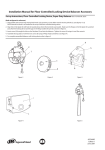
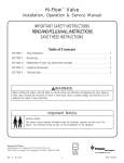
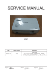
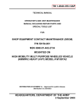
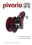
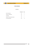
45527801
Edition 1
May 2007
Electric Screwdrivers
ES45T, ES50T and ES50TC
Maintenance Information
Save These Instructions
WARNING
Always wear eye protection when operating or performing maintenance on this tool.
Always turn off the air supply and disconnect the air supply hose before installing, removing or adjusting any accessory on this tool or
before performing any maintenance on this tool.
Note: (When reading the instructions, refer to exploded diagrams in parts Information Manuals when applicable (see under Related Documentation
for form numbers).
Clutch Spring Selection Chart
Part Number
ES50T-43 1
ES50T-462
Part Number
ES50T-431
ES50T-462
Model ES45
Torque Range
0.3 to 2.6 in-lb (0.04 to 0.30 N m)
1.2 to 6.5 in-lb (.I4 to .74 N m)
Model ES50T and ES50TC
Torque Range
0.5 to 3.0 in-lb (0.06 to 0.34 N m)
2.0 to 9.0 in-lb (0.23 to 1.02 N m)
Disassembly
1. For Models ES45T and ES5OT, unscrew and remove the
Coupling (55). This is a left-hand thread; turn clockwise to remove.
For Model ES5OTC, unscrew and remove the Nose Collar (61).
2. Using a Phillips Screwdriver, remove the three Housing Screws (2).
This is a left-hand thread; turn clockwise to remove.
3. Carefully separate the right side of the Housing from the left side
of the Housing.
NOTICE
The Model ES5OTC Screwdriver housing is assembled using a
liquid gasket as a sealing material. Carefully pry the housing
sections apart using a thin, flat piece of metal. Do not use heat or
chemical solutions to seperate the two halves.
4. Lifting the spindle end of the assembly slightly, carefully pull the
Gear Case (37) and assembled clutch away from the Motor.
5. Trigger Switch (8) replacement
a. Lift the Trigger Switch out of its recess in the left side of the
Housing (1) and unsolder the connections.
b. Solder the leads to a new Trigger Switch and reposition the
Switch in the Housing. (Refer to the wiring diagram below).
6. Reverse Switch (9) replacement
a. The Reverse Switch is fitted into the left side of the Housing.
Remove the Switch by depressing the locking tab of the
switch mount from the rear with a flat blade Screwdriver and
pushing the Switch out of the Housing.
b. Unsolder the wiring to the Switch and install a new Switch.
(Refer to the wiring diagram below).
BRAKE SWITCH
TRIGGER SWITCH
RED
BLACK
4
POWER CORD
1
2
3
1
2
3
RED
WHITE
5
RED
BLUE
GREEN
YELLOW
2
1
M
MOTOR
BLUE
FORWARD/REVERSE SWITCH
(VIEWED FROM REAR)
E
BLU
RED
RED
Wiring diagrams for ES45T, ES50T and
ES50TC Electric Screwdrivers
7. Brake Switch (15) replacement
a. Remove the two Screws (16) holding the Brake Switch.
b. Unsolder the wiring to the Brake Switch and install a new
Switch. (Refer to the wiring diagram above).
c. Position the Brake Switch and install the two Screws to secure
it to the Shutoff Switch Plate (10).
d. After installing the Brake Switch, loosen the Switch Plate
Screw (11) that holds the Switch Plate in the Housing.
e. Move the Switch Plate toward the Motor and tighten the
Screw when the Switch is pushed .014 + or -.002 beyond the
“ON” point (point that the Switch clicks). Placing a .014” shim
on the arm of the Switch and moving the Switch until it clicks
is a simple method of setting the Brake Switch gap.
Models ES45T, ES50T and ES50TC Electric Screwdrivers
“ON” POINT (SWITCH “CLICKS”)
BRAKE
SWITCH
.014 ± .002
SWITCH PLATE
SCREW
(Dwg. TPD1113)
8. Brush Assembly (24) replacement
a. Unsolder the brush lead.
b. Lift the brush spring end upward and over the corner of the
phenolic tab. Remove the brush.
c. Solder the brush lead onto a new brush, install the brush and
reposition the brush spring. (d) Repeat steps (a), (b) and (c) for
the remaining brush.
9. Power Cord Assembly (6) replacement
a. Unsolder the wires to the Trigger Switch (S), Brake Switch (15)
and the green and yellow wires of the Power Cord where the
leads from the Reverse Switch (9) are spliced.
b. Install a new Power Cord Assembly and solder the wires to the
Trigger Switch, Brake Switch and two leads from the Reverse
Switch as shown in the wiring diagram on page 12.
* Trademark of Permabond International.
(Dwg. TPD1114)
45527801_ed1
10.Motor Assembly replacement
RED
BLUE
NOTE HOLE
LOCATION
(Dwg. TPD1052)
a. Unsolder the two motor leads. Note the location of the red
and blue leads to the hole in the side of the motor.
b. Solder the motor leads to a new motor as illustrated above.
c. Carefully check the Reverse Switch (9) to make sure that the
motor runs in the correct rotation as indicated on the Switch.
If the motor does not run in the correct rotation, reverse the
leads.
NOTICE
Model ES5OTC has a Shield Plate (20) separating the motor from
the switches. When installing the assembled motor, make certain
Perma-Lok GasketMaker* HH190 liquid gasket material forms a
seal around the edge of the Plate and also at the opening in the
Plate for the motor leads.
11.Pushrod replacement
a. Remove the Gear Case (37) from the Motor Assembly.
b. Pull the Pushrod (35) out of the motor and replace it with a
new one.
c. Pull the Pushrod (46) out of the Gear Case. Lightly coat a new
Pushrod with Ingersoll Rand No. 67 Grease and insert it into
the Gear Case.
d. After replacing both Pushrods, adjust the timing of the Switch
Plate (10) as described in Step 7(e).
12.Gear replacement
a. Pull the Gear Case (37) away from the Motor Assembly.
b. The joint between the Gear Case and Clutch Housing (53) is a
left-hand thread. Using one wrench on the gear case flats and
another on the flats of the Clutch Housing, turn the Housing
clockwise to separate the two parts.
c. Remove the Cam (43), two Cam Pins (44), Thrust Washer (42),
Spindle Assembly (40) and Gear Head Assembly (38) from the
clutch end of the Gear Case.
d. Inspect the Gear Head Planet Gears (39), Spindle Planet
Gears (41) and the gear teeth in the Gear Case for chipped or
broken teeth. Apply a small amount of Ingersoll Rand No. 67
Grease to the Gears, Gear Case and Cam.
e. Insert the Gear Head Assembly, Planet Gears first, into the
clutch end of the Gear Case. Make certain the Planet Gears
mesh with the gear case spline.
f. Insert the Spindle Assembly, gear end leading, into the Gear
Case. Make certain the Spindle Planet Gears mesh with the
pinion of the Gear Head. Install the Thrust Washer, Cam,
Cam Pins and Collar into the Gear Case.
g. The joint connecting the Gear Case to the Clutch Housing is a
left-hand thread. Thread the Housing onto the Gear Case in a
counterclockwise direction and tighten the joint to
21 ft-lb (28.5 Nm) torque.
13.Place the assembled motor, gearing and clutch unit in the left
side of the Housing.
14.For Models ES45T and ES5OT, place the right side of the
Housing against the left side and install the three Housing
Screws.
For Model ES5OTC, place a bead of Perma-Lok GasketMaker*
HH190 around the edge of Shield Plate and the mating edges of
the Housing. Place the right side of the Housing against the left
side and install the three Housing Screws.
15.For Models ES45T and ES5OT, thread the Coupling (55) onto the
Gear Case and tighten it with a wrench.
For Model ES5OTC, thread the Nose Collar (61) onto the Gear
Case and tighten it with a wrench.
Troubleshooting Guide
Trouble
Probable Cause
Solution
Is there power to the tool?
1. Defective Power Cord Assembly (6). Replace the Power Cord
Assembly if necessary.
2. No power from the Controller. Repair or replace (see Controller
Service Manual).
Does the Trigger Switch click when the Trigger
is depressed?
Defective Trigger Switch (8). Replace the Trigger Switch.
Does the Trigger Switch turn on power to
the Motor?
Trigger pad worn. Replace the Trigger (17).
Can the bit be turned by hand when the tool
is unplugged?
1. Planetary gearing defective. Replace the Planet Gears (39 or
41), Spindle Assembly (40) and Gear Head Assembly (38).
2. Clutch defective. Repair or replace the clutch.
Does the tool operate properly when bumped
and jiggled?
1. Defective power cord. Replace the Power Cord Assembly (6).
2. Forward/Reverse Switch defective. Replace the Forward/
Reverse Switch (9).
3. Defective solder connection.
Check all solder connections; resolder where necessary.
4. Defective Armature. Replace the Motor Assembly.
5. Brush contact defective. Replace the Brush Assembly.
Does brush wear appear normal?
1. Worn or defective Brushes. Replace the Brush Assemblies (24).
2. Defective Commutator. Replace the Armature (31).
Does motor appear to be in good condition?
1. Carbon buildup or dirt on Armature (31).
2. Clean the Armature using a good electrical contact cleaner
and blow dry.
Screwdriver fails
to rotate (reverse or
forward)
45527801_ed1
Trouble
Screwdriver runs in
one direction but
not the other
Bit does not rotate
but motor hums.
Probable Cause
Defective solder connections. Resolder and rewire if necessary.
Does Reverse Switch operate properly?
Defective Reverse Switch (9). Replace it.
When gears are removed, will the motor
rotate?
Is planetary gearing smooth when bit is
rotated by hand?
Does the speed of the Bit exceed rated speed
by more than 100 rpm?
Shutoff brake
malfunctions more
than one index of
the Clutch.
Is Brake Switch functioning? (Does it click
when button is depressed and does it test
correctly with an ohmmeter?)
Does Pushrod (35 or 46) function properly?
Does Cam (43) function properly?
Is there looseness at the assembly points?
Tool makes
abnormal sounds
when the motor is
running.
After removing the gear train does motor
sound normal when running?
Is the gear train properly lubricated?
Tool generates
abnormal heat when
operating.
After removing the gear train, does tool cool
down and motor run normally?
Is the shutoff brake functioning properly?
Tool outputs high
torque.
Tool outputs low
torque.
Solution
Are wire leads in good condition
and properly soldered?
Is Clutch properly lubricated?
Is there wear on face of cam guide where it
contacts Spindle Assembly (40)?
Is the Clutch Housing joint tight?
1. Armature (31) is in contact with the magnets. Replace the
motor.
2. Foreign material in the motor. Clean the motor.
1. Bearing has failed. Replace the Spindle Assembly (40).
2. Gears are worn or damaged. Replace any defective gearing.
3. Clutch Assembly is worn. Replace damaged or worn parts.
Motor magnet is demagnetized. Replace the motor.
Defective Brake Switch (15). Replace the Brake Switch.
1. Bent or worn Pushrod (35 or 46). Replace it.
1. Cam is worn and not providing adequate lift.
Replace the Cam.
Controller malfunctioning or defective.
Repair or replace. See Controller Service Manual.
1. Screws (2) are loose. Tighten all Screws.
2. Clutch Housing is loose. Tighten the Clutch Housing to the
proper torque.
1. Armature (31) is in contact with the Magnet. Replace the
motor.
2. Foreign material has gotten into the motor. Clean or replace
the motor.
3. Ball Bearings are defective. Replace the Motor.
4. Armature is defective. Replace the Motor.
No grease on the gear train.
Apply a thin film of the recommended grease to the gear train.
1. Spindle Bearing has failed.
Replace the Spindle Assembly (40).
2. Gears are worn or dirty. Clean or replace the Gears.
Motor is defective. Replace the motor.
Planetary gears and the Clutch require lubrication.
Lubricate the Clutch and gear train with the recommended
grease. Note: Do not apply tooI much or too little grease.
Refer to Problem No. 4 to check shutoff brake malfunctions.
No lubrication on the Clutch Components. Lubricate the Clutch
with recommended Grease.
Cam guide is worn. Replace the Bit Holder Assembly.
Clutch Spring (51) is damaged. Replace Spring.
Loose joint between the Gear Case (37) and Clutch
Housing (53).
Tighten the joint iwth a torque wrench to specified torque.
1. Cam (43) is worn. Replace the Cam.
2. Clutch Spring (51) is damaged. Replace the Clutch Spring.
3. Cam guide is damaged. Replace the Bit Holder
Assembly (48).
Related Documentation
For additional information refer to:
Product Safety Information Manual 16602963.
Product Information Manual 45527702.
Parts Information Manual 45527777.
Manuals can be downloaded from www.irtools.com.
45527801_ed1
Notes:
Notes:
Notes:
www.irtools.com
© 2007 Ingersoll Rand Company