1
JAA63051-R.3689.A
作成承認印
配布許可印
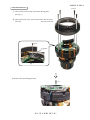
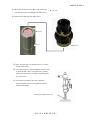
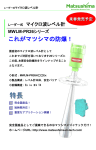
AF-S VR Micro Nikkor
105mm / f2.8G
JAA63051 (MADE IN JAPAN)
REPAIR MANUAL
Copyrigh c 2006 by Nikon Corporation.
All Rights Reserved.
無断転載を禁ず !!
Printed in Japan Mar.2006
JA63051-R.3689.A
Specifications
Type of lens:
G-type AF-S Micro-Nikkor lens with built-in CPU and Nikon bayonet mount
Focal length:
105mm
Maximum aperture:
f/2.8
Lens construction:
14 elements in 12 groups (1 ED glass and 1 Nano Crystal Coat-deposited
lens elements)
Picture angle:
23°20’ [15°20’ with Nikon digital cameras (Nikon DX format); 18°40’ with
IX240 system cameras]
Reproduction ratio:
1:10 to 1:1 (life-size)
Distance information:
Output to camera body
Focusing:
Nikon Internal Focusing (IF) system (utilizing an internal Silent Wave
Motor); manually via separate focus ring
Focusing limit switch:
Provided; two ranges available: Full ( ‡-0.314m) or‡-0.5m
Vibration reduction:
Lens-shift method using voice coil motors (VCMs)
Shooting distance scale: Graduated in meters and feet from 0.314m (1 ft.) to infinity ( ‡)
Closest focus distance:
0.314m (1 ft.) (life-size)
No. of diaphragm blades: 9 pcs. (rounded)
Diaphragm:
Fully automatic
Aperture range:
f/2.8 to f/32
Exposure measurement: Via full-aperture method
Attachment size:
62mm (P = 0.75mm)
Dimensions:
Approx. 83mm dia. x 116mm extension from the camera’s lens mount
flange
Weight:
Approx. 790g (27.9 oz)
Specifications and designs are subject to change without any notice or obligation on
the part of the manufacturer.
- M1・AF-S VR 105/2.8G -
※ Before Disassembly / (Re)assembly / Adjustment
JAA63051-R.3689.A
On this lens, the VR (vibration-reduction) unit is mounted to correct the picture blur.
In order to maintain the functional accuracy of the picture blur correction, if detaching the VR
(vibration-reduction) unit and gyro base plate or if removing the main PCB unit, be sure to adjust the VR by
using the VR lens adjustment equipment (J15380).
However, if disassembling the parts except the above, the VR adjustment is NOT necessary.
At service agencies where the "VR lens adjustment equipment" is not prepared, do NEITHER disassemble
NOR repair the products of the above case.
Removing the 1-1st lens group or 5th lens group of this lens needs the lens alignment work after the assembly.
Therefore, at service facilities where the lens alignment cannot be performed, do NOT remove the 1-1st lens
group nor 5th lens group.
Caution:
① When disassembling, make sure to memorize the processing state of wires, screws to be fixed and their types, etc.
② Because prototypes are used for "Disassembly/(Re)assembly/Adjustment", they may differ from the actual
products in forms, etc.
③ Because pictures are processed by a special method, they may differ from the actual ones in texture.
Points to notice for Lead-free solder products
・Lead-free solder is used for this product.
・For soldering work, the special solder and soldering iron are required.
・Do NOT mix up lead-free solder with traditional solder.
・Use the special soldering iron respectively for lead-free solder and lead solder.
They cannot be used in common.
- D1・ AF-S VR MC 105/2.8G -
JAA63051-R.3689.A
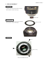
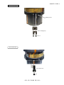
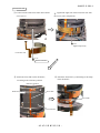
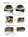
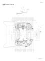
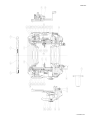
1. DISASSEMBLY
VR name plate
・ Remove the VR name plate (which is attached
with the adhesive double-coated tape).
VR name plate
Front cover sheet
・ Remove the front cover sheet (which is attached
Front cover sheet
with the adhesive double-coated tape).
Rear cover ring
#38×3
Rear cover ring
- D2・ AF-S VR MC 105/2.8G -
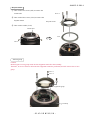
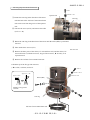
JAA63051-R.3689.A
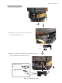
Bayonet mount
① Take out the two screws (#66) to remove the
contact unit.
#136×4
② Take out the four screws (#136) to remove the
bayonet mount.
Bayonet mount
③ Take out the washer (#176).
Contact unit
#176
#66×2
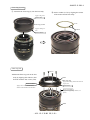
5th lens group
Caution:
Removing the 5th lens group needs the lens alignment work after the assembly.
Therefore, at service facilities where the lens alignment cannot be performed, do NOT remove the 5th lens
group.
#113×3
#151×3
5th lens group
Lens body
- D3・ AF-S VR MC 105/2.8G -
JAA63051-R.3689.A
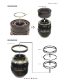
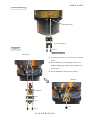
VR lens group unit
★ New tool
① Turn the VR SW to OFF.
② Align the concave portion of the VR-fixing tool ( ★ J11321)
★ J11321
and the FPC of the contact unit, and fit the two pins of the
tool into the two holes of the lens. Then assemble the VRfixing tool into the lens.
Pin × 2
Hole×2
Concave
portion
Contact
unit
③ Remove the VR lens group and washer(s) (#138 selected from A ~ J) with the VR lens-assembling tool
( ★ J11324).
④ Remove the VR-fixing tool ( ★ J11321) from the lens.
VR lens
G-assembling tool
( ★ J11324)
★ J11321
VR lens group
#138A ~ J
- D4・ AF-S VR MC 105/2.8G -
JAA63051-R.3689.A
3rd lens group
3rd lens group
3rd lens-G
assembling tool
( ★ J11323)
2nd lens group, 1-2nd lens group, 1-1st lens group
Removing the 1-1st lens group needs the lens alignment work after the assembly.
Therefore, at service facilities where the lens alignment cannot be performed, do
NOT remove the 1-1st lens group.
① Take out the four screws (#142) and the four washers (#151). Then
remove the 1-1st lens group and the washer(s) (#152 selected from
#142×4
#151×4
A-J).
② Remove the
1-2nd
lens group and the washer(s) (#137 selected from
1-1st lens G
A-J) with the 1-2nd lens-G assembling tool ( ★ J11320).
#152A ~ J
③ Remove the 2nd lens group.
1-2nd lens G
#137A ~ J
2nd lens G
- D5・ AF-S VR MC 105/2.8G -
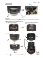
JAA63051-R.3689.A
Rubber ring
Rubber ring
Filter ring unit
#69×4
Filter ring unit
- D6・ AF-S VR MC 105/2.8G -
JAA63051-R.3689.A
Focus ring (2) unit
Focus ring (2) unit
#175
Focus ring (1) unit
Focus ring (1) unit
#139×2
#27
#139×2
- D7・ AF-S VR MC 105/2.8G -
JAA63051-R.3689.A
MF brush unit
Red: MF brush unit
Black: MF brush unit
#163×2
Power source brush unit
Black: Power source brush unit 1
Red: Power source brush unit 1
Yellow: Power source brush unit 1
Yellow: Power source brush unit 2
Red: Power source brush unit 2
Black: Power source brush unit 2
Caution: After removing the wires, suck the solder off completely. Otherwise, the SWM
unit cannot be removed.
FS40(#56)
#163×2
#163×2
- D8・ AF-S VR MC 105/2.8G -
JAA63051-R.3689.A
SWM unit
#211×4
#148
#147
#148×3
#147×3
Caution:
When disassembling, Do NOT touch the upper
surface of the pattern.
#166
#167
SWM unit
- D9・ AF-S VR MC 105/2.8G -
JAA63051-R.3689.A
Change SW unit
SW FPC
Soldering bridge×4
#132
Change-SW unit
Name plate
window (Misdescription)
Caution: The name plate and focus ring do not have to be removed except the case when parts are replaced.
① Remove the name plate (#95) (which is attached with
② Remove the focus window (#94) (which is
attached with the adhesive double-coated
the adhesive double-coated tape).
tape).
#94
#95
External tube unit
External
tube unit
#119×2
SW FPC
#118
Changed page
×1
- D10 ・ AF-S VR MC 105/2.8G -
May. 26. 2006
JAA63051-R.3689.A
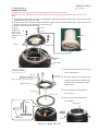
Focus index unit
#83×3
Focus index unit
GMR unit
- D11 ・ AF-S VR MC 105/2.8G -
JAA63051-R.3689.A
Rear outer tube unit
#154×4
① Take out the screw (#144), and remove the lug plate.
(ref. Fig. 1)
② Take out the four screw (#154), and remove the rear outer
tube unit.
Rear outer tube unit
#144
Lug plate
Fig. 1
③ Remove the positioning pin (#97).
#97
- D12 ・ AF-S VR MC 105/2.8G -
JAA63051-R.3689.A
Mechanical-coupled block
① Take out the screw (#113).
#113
② Take out the two screws (#113), and remove the
block-retaining plate (#184).
#184
#113×2
③ Remove the mechanical-coupled block. Then attach the screw
(#113) temporarily that was taken out in ① .
Mechanical-coupled
block
#113
VR ON/OFF-change
brush
#169
- D13 ・ AF-S VR MC 105/2.8G -
JAA63051-R.3689.A
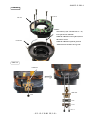
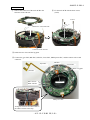
Main PCB unit
Gyro-FPC
MR FPC
Focus FPC
Black: Lug plate
SW FPC
Blue: VR FPC
Contact unit
Black: VR FPC
SWM power FPC
Peel off the adhesive double-coated tape.
#140×3
Connector of the main PCB
Connector of VR unit
- D14 ・ AF-S VR MC 105/2.8G -
JAA63051-R.3689.A
VR unit
#160×4
VR unit
Caution:
The washer(s) (191: selected from A ~ G)
is/are put in some VR units.
When the VR unit is NOT replaced, insert
this wahser as it is.
Fixed tube
When the VR unit is replaced, perform
"Slant check of VR unit" on Page A12.
GMR unit
GMR FPC
GMR unit
#144
#124
#123
#83×2
- D15 ・ AF-S VR MC 105/2.8G -
JAA63051-R.3689.A
Focus coupling key
GMR tape unit
Focus coupling key
#163×2
Focus brush unit
Focus brush unit
#83
- D16 ・ AF-S VR MC 105/2.8G -
JAA63051-R.3689.A
GMR tape unit
Caution 1:
#98×2
Do NOT touch the tape of the GMR tape unit directly
with hands.
#99×2
#96×2
GMR tape unit
① Take out the two screws (#98) through the holes
of the GMR tape unit, and remove the two rollers
GMR tape
(#99) and the two washers (#96).
A
② Rotate the GMR tape unit in the direction of the
arrow "A" all the way to the limit, then remove it
upwards.
Fixed tube
Focus restriction section
Focus restriction section
#120
Fixed tube
Fixed tube
#79
#134
#133
- D17 ・ AF-S VR MC 105/2.8G -
JAA63051-R.3689.A
Focus FPC unit
① Peel off the focus FPC from the fixed tube.
② Peel off the focus FPC from the fixed tube.
Focus FPC
Focus FPC
Fixed tube
③ Take out the right-side screw (#113) of the
④ Take out the left-side screw (#113) of the focus
FPC unit, and remove the focus FPC unit.
focus FPC unit.
#113
Focus FPC unit
#113
- D18 ・ AF-S VR MC 105/2.8G -
JAA63051-R.3689.A
3rd lens-group movement-frame unit
#158
Aperture unit
#157A ~ D
① Rotate the cam ring in the direction of the arrow
until the hole of the 3rd lens-G movement frame
Cam ring
unit can be seen from the groove of the aperture
unit.
② Take out the screw (#158), and remove the roller
(#157A ~ D).
③ Rotate the cam ring in the direction of the arrow until the roller (B28) is positioned
lowered.
④ Take out the three screws (#78).
★ New tool
⑤ Remove the three pairs of the roller (#77 selected from A-F) and the roller (#76
selected from A-F) with the new tool, X-type slim tweezers ( ★ J11326), or an
equivalent tool.
⑥ Remove the 3rd lens-G movement frame unit.
● Fold the tip of the X-type slim tweezers
( ★ J11326) as below, and use it.
#78×3
#77A ~ F×3
Approx.70° ~ 80°
Approx.1.5mm
Roller (B28)
Folding of X-type slim
tweezers
Cam ring
3rd lens-G movement frame unit
- D19 ・ AF-S VR MC 105/2.8G -
#76A ~ F×3
JAA63051-R.3689.A
Aperture unit
#92×2
Lens body
#114
#113×2
Aperture unit
- D20 ・ AF-S VR MC 105/2.8G -
JAA63051-R.3689.A
Gyro-FPC
#113
#113
SWM power FPC
・ Peel off the SWM power FPC from the fixed tube unit.
(SWM power FPC is attached with the adhesive double-coated tape.)
SWM power FPC
- D21 ・ AF-S VR MC 105/2.8G -
JAA63051-R.3689.A
VR FPC
・ Peel off the VR FPC from the fixed-tube unit.
(VR FPC is attached with the adhesive double-coated tape.)
Adhesive double-coated tape (#183)
- D22 ・ AF-S VR MC 105/2.8G -
VR FPC
JAA63051-R.3689.A
2 ASSEMBLY / ADJUSTMENT
VR FPC
・Attach the VR FPC on the fixed lens-barrel unit.
(VR FPC already has the adhesive double-coated tape adhered.)
・ Attach the adhesive double-coated tape (#183) at the below position.
Reference position for
attachment
Adhesive double-coated tape (#183)
VR FPC
SWM power FPC
・Attach the SWM-power FPC on the fixed lens-barerl unit.
(SWM-power FPC already has the adhesive double-coated tape adhered.)
Reference position for attachment
SWM-power FPC
- A1・ AF-S VR MC 105/2.8G -
JAA63051-R.3689.A
Gyro-FPC
① Attach the gyro-FPC on the fixed lens-barrel unit.
(Gyro-FPC already has the adhesive double-coated tape adhered.)
② Fix it with the two screws (#113).
Mountain-fold
Mountain-fold
#113
#113
- A2・ AF-S VR MC 105/2.8G -
JAA63051-R.3689.A
② Set the key (#114) by fitting its upper part in the
Aperture unit
① Align the grooves of the aperture unit and the lens
body, and assemble them.
groove of the aperture unit. Then fix it with the two
screws (#113).
Groove
Lens body
#114
#113×2
Adhesive:Lockend B
Groove
Aperture unit
Grease: G92KA
Apply to groove.
③ Fix the aperture unit with the two screws (#92).
#92×2
Adhesive:Lockend B
- A3・ AF-S VR MC 105/2.8G -
JAA63051-R.3689.A
3rd lens-group movement-frame unit
① Rotate the cam ring in the direction of the arrow until the roller (B28) is positioned lowered.
② Put the 3rd lens-G movement-frame unit inside the cam ring as shown below.
③ Fix three pairs [of the roller (#76 selected from A-F) and the roller (#77 selected from A-F)] with the
three screws (#78).
Caution: Choose rollers (#76 and #77) which are slightly tight for each groove.
#78×3
#77A ~ F×3
#76A ~ F×3
Roller B28
Cam ring
3rd lens-G movement frame
#158
Aperture unit
④ Rotate the cam ring in the direction of the arrow until
the screw hole of the 3rd lens-G movement frame
can be seen from the groove of the aperture unit.
⑤ Fix the roller (#157 selected from A ~ D) with the
screw (#158).
- A4・ AF-S VR MC 105/2.8G -
#157A ~ D
Cam ring
JAA63051-R.3689.A
Focus FPC unit
① Fix the left side of the focus FPC unit with the
screw (#113).
② Tighten the right side of the focus FPC unit with
the screw (#113) temporarily.
#113
Tighten temporarily
Focus FPC unit
#113
Adhesive:Lockend B
④ Attach the focus FPC by conforming to the shape
③ Attach the focus FPC on the fixed tube,
of the fixed tube.
according to the reference position.
Reference position
Reference position
Focus FPC
Focus FPC
Fixed tube
- A5・ AF-S VR MC 105/2.8G -
JAA63051-R.3689.A
Focus restriction section
① Assemble the teflon sheet (#120) in the fixed tube.
② Fix the restriction rubber (#134) and the washer
(#79) on the fixed tube with the screw (#133).
#120
Fixed tube
Fixed tube
#79
#134
#133
Adhesive:Lockend B
GMR tape unit
Caution 1:
Adhesive:Lockend B
Do NOT touch the tape of the GMR tape unit
#98×2
directly with hands.
Caution 2:
The ball-bearing visible side of the roller (#99) must
Concave
portion
come to the washer (#96)-side.
Caution 3:
GMR tape
The chamfered side of the washer (#96) must come
to the roller (#99)-side.
① Align the concave portion of the GMR tape unit
with the focus restriction portion, then assemble
the GMR tape unit into the fixed tube.
Fixed
tube
② Fix each two pairs [roller (#99) and
washer (#96)] with the screws (#98)
by passing the body of the screws
(#98) through the holes of the GMR
Focus restriction section
tape unit.
- A6・ AF-S VR MC 105/2.8G -
#99×2
#96×2
GMR tape unit
JAA63051-R.3689.A
(Focus) Encoder brush unit
① Fix the encoder brush unit on the GMR tape unit
with the screw (#83) temporarily.
GMR tape unit
"∞ (infinity)" position of the
focus pattern.
Encoder brush unit
★ New RJ
#83
② Rotate the GMR tape unit until the "A" hole is
aligned with the "∞" hole of the inner cam ring of
the fixed tube.
ref: The above position of "∞" hole of the cam ring is
almost at the place where the brushes are positioned
at "∞" of the focus pattern.
③ Insert the tool ( ★ J11319) in "A" hole.
"A" hole
Infinity positioning pin
★ J11319
④ Loosen the screw (#83) and move the encoder brush
unit from side to side. Adjust so that the contact
surface of the brush is at "∞" position of the focus
pattern.
⑤ Tighten the screw (#83) and apply the screwlock.
⑥ Remove the tool (J11319) from "A" hole.
"∞ (infinity)" position of the
focus pattern.
#83
Adhesive: Screwlock
- A7・ AF-S VR MC 105/2.8G -
JAA63051-R.3689.A
Focus coupling key
GMR tape unit
Focus coupling key
GMR unit
#163×2
Adhesive:Lockend B
Tool-pin hole
① Insert the drill with φ1.2, etc into the two tool-pin
holes.
② Fix the GMR unit, retaining plate (#124), and
GMR-retaining plate spring (#123) with the two
screws (#83).
③ Fix the GMR FPC with the screw (#144).
GMR FPC
GMR unit
#124
#123
#83×2
- A8・ AF-S VR MC 105/2.8G -
#144
JAA63051-R.3689.A
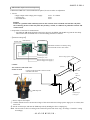
MR encoder output-waveform inspection
● When the GMR unit is disassembled and replaced, be sure to make an adjustment.
1. Device:
・Single-output rated voltage power-supply
・ Oscilloscope
・ Self-made tool
1 unit: 5V 100mA
1 unit
1 unit Caution:
If there is a problem with continuity between the contacts of the self-made tool and the relay FPC,
the contacting surface of the relay FPC may be dirty, eroded, or oxidized. So polish the contacts and
connect them.
2. Preparation of the lens for measurement
・ Assemble the MR-head-attached zoom index ring unit, the SWM, and the MF ring into the lens body.
Then connect the assembled lens to each measuring machines as follows:
・
【Attachment diagram】
To back side
PCB (Front)
PCB (Back)
Self-made tool that is created by using
the main PCB of AF-S VR 18-200
Oscilloscope (2ch)
Oscilloscope (1ch)
Rated voltage power-supply (+)
Rated voltage power-supply (-)
Rated voltage power-supply
Caution:
(GND)
The connector of the back of the
PCB is not used.
Connect to the front-side connector of the
self-made tool PCB.
GMRFPC
(+)
Set value
5.0 V
100 mA
Self-made tool
GMR tape unit
Oscilloscope
(2ch type)
・How to inspect and adjust:
① Confirm that the electric current and voltage of the connected rated voltage power-supply are set values, then
turn it ON. ② Set the oscilloscope, and turn the GMR tape unit by holding the focus coupling key. Note: The waveform varies according to the rotational speed of the focus ring. So change “Time/Div” setting
accordingly.
- A9・ AF-S VR MC 105/2.8G -
JAA63051-R.3689.A
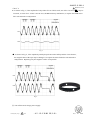
● Oscilloscope setting
V/Div (ch1) :50 mV
V/Div (ch2) : 50 mV
Coupling : AC
Time/Div :5 m Sec
Trigger Mode :NORMAL
CH1
Trigger Coupling : AC
Trigger Source :CH1
Trigger Position : + 4 div
Amplitude
CH2
Trigger Type :EDGE
Trigger Level : 0V
INPUT (ch1) :AC
INPUT (ch2) :AC
Fig. 1
Standard: Amplitude of all pulses/waveforms is 130 mV or more.
Note: Check the waveform by moving the focus ring back and forth
from the infinity-end to the close-end positions entirely.
③ In case large waveform-noise (as shown in Fig. 1) is detected, use the FILTER function.
How to set FILTER function (e.g. DL1540 manufactured by YOKOGAWA)
1. Press the FILTER button.
2. Select “Smooth” of the menu on screen and turn it ON.
④ In case the amplitude is small, disassemble up to the stage
of the GMR sensor FPC unit. Then if the deformation is
detected in the MR head, correct the deform of the MR
GMR unit
head. On the other hand, if such correction is impossible
or no deformation is detected, replace the GMR sensor
FPC unit. (Fig.2)
MR head
Note: When adjustments are made, prevent the magnetic
surface and MR head from touching the magnetized
driver bit. Otherwise, the magnetic data may be
damaged.
- A10 ・ AF-S VR MC 105/2.8G -
Fig.2
JAA63051-R.3689.A
< Ref. >
(Misdescription)
83
● As shown in Fig. 3, if the amplitude of only either CH1 or CH2 is small, one of the 2 screws (#123) may be
loosened, so check for it. If this is not the case, the MR head may malfunction, so replace the GMR sensor
FPC unit and make a readjustment.
CH1
CH2
Fig. 3
● As shown in Fig. 4, if the amplitude partially drops between the infinity and the close-distance,
the magnetic data of the tape may be damaged. So replace the main fixed tube unit and make a
readjustment. Replacing only the magnetic surface is impossible.
CH1
CH2
GMR tape unit
Fig. 4
⑤ Turn off the rated voltage power-supply.
Changed page
×1
- A11 ・ AF-S VR MC 105/2.8G -
May. 26. 2006
JAA63051-R.3689.A
VR unit
・Tighten the four screws (#160) in the
③
②
①
order from ① to ④ .
④
#160×4
VR unit
Caution:
The washer(s) (191: selected from A ~ G)
is/are put in some VR units.
When the VR unit is NOT replaced, insert
this wahser as it is.
When the VR unit is replaced, perform
"Slant check of VR unit" on the next page.
Fixed tube
★ New tool
Slant check of VR unit
★ J11321
① Mount the VR fixing tool ( ★ J11321) by
fitting in the holes of the VR unit.
- A12 ・ AF-S VR MC 105/2.8G -
JAA63051-R.3689.A
② Mount the VR mirror tool ( ★ J11330) on the VR
unit with the mirror-assembling tool ( ★ J11331).
★ New tool
③ Remove the VR-fixing tool ( ★ J11321).
★ J11330
★ J11331
③ Place a parallel glass or parallel mirror, etc, on the
measurement stand.
※ For a parallel glass, a super telephoto, G1 lens, such
as AF-S300 mm can be used, while for a parallel
mirror, the main-mirror 45-degree positioning tool,
etc, can be used.
④ Fine-tune the position of the auto collimator,
and perform the optical axis alignment with the
measurement stand.
Parallel glass, parallel mirror, etc
- A13 ・ AF-S VR MC 105/2.8G -
★ J11321
JAA63051-R.3689.A
⑤ Remove the parallel glass which was placed on the
measurement stand. Set the fixed tube as shown in the
right picture.
⑥ As shown in the right picture, measure a position
difference of the cross lines, which are indicated by
the mirror tool and the collimator.
Cross lines of the mirror tool
③
・ Tighten the four screws (#160) in the
order from ① to ④ .
①
②
④
#160×4
Adhesive:
Screwlock
VR unit
⑦ If the above difference is 4 min or more, select
and put the washer (#191A ~ G) in order to
correct the slant.
⑧ Remove the mirror tool after the adjustment.
Fixed tube
- A14 ・ AF-S VR MC 105/2.8G -
#191A ~ G
JAA63051-R.3689.A
Main PCB unit
① Connect the connector of the main PCB to the
connector of the VR unit.
② Fix the main PCB with the three screws
(#140).
#140×3
Connector of the main PCB
Connector of the VR unit
③ Solder the two wires and the lug plate.
④ Connect the gyro-FPC, MR-FPC, SW-FPC, focus-FPC, SWM power-FPC, and the contact unit to each
connector.
Gyro-FPC
MR-FPC
Black: Lug plate
SW-FPC
Blue: VR FPC
Focus-FPC
Contact unit
Black: VR FPC
SWM power-FPC
Arrange the two wires and attach them on
the adhesive double coated tape.
- A15 ・ AF-S VR MC 105/2.8G -
JAA63051-R.3689.A
Mechanical-coupled block
① Take out the setscrew (#113) of the focus-FPC,
Apply to the edge surface of vertical groove.
and attach the mechanical-coupled block by
Grease: G92KA
fitting the coupling pin in the concave portion of
the mechanical-coupled block.
#113
Mechanical-coupled
block
VR ON/OFF-change
brush
#169
Grease: G92KA
Adhesive: Screwlock
② Attach the block retaining plate (#184), and fix it
with the two screws (#113).
#184
Adhesive: Lockend B
#113×2
③ Attach the screw (#113) that was taken
out in ① .
#113
Adhesive: Lockend B
- A16 ・ AF-S VR MC 105/2.8G -
JAA63051-R.3689.A
Rear outer tube unit
#97
① Insert the positioning pin (#97).
Adhesive: Lockend B
Apply to the hole.
Adhesive: Lockend B
#154×4
② Mount the rear outer tube unit, and
tighten the four screws (#154).
③ Press the lug plate towards the
direction of "A", and fix it with the
screw (#144). (ref. Fig. 1)
Rear outer tube unit
Apply to the overall
circumferential surfaces
of the level difference.
Grease: OS-30MF
Caution:
If the lug plate is tilted when attached, the 5th
lens-G alignment becomes impossible. Therefore,
attach so that the lug plate is parallel to the wall of
the rear outer tube unit.
#144
Lug plate
A
Fig. 1
- A17 ・ AF-S VR MC 105/2.8G -
JAA63051-R.3689.A
Bayonet mount (temporary attachment)
① Put the washer(s) (#176 selected from A-M) by fitting position of the holes.
② Insert the aperture lever (#109) of the bayonet mount into the aperture unit by fitting in the bending part of
the aperture unit.
③ Fix the bayonet mount with the four screws (#136) (temporarily).
#136×4
#103
Direction for
#30
#100×2
#23
positioning
#28
#104
Adhesive: Screwlock
#109
#101
#109
Bayonet mount
Grease: I-40
Apply to the edge face of #109.
#176A ~ M
#109
Aperture unit
- A18 ・ AF-S VR MC 105/2.8G -
JAA63051-R.3689.A
Position adjustment of Aperture lever
① Rotate the focus coupling key in the direction of the arrow all the way J18004-1
to the limit. (close-end)
② Mount the tool (J18004-1). Check the aperture diameter by looking
through at the aperture from the opposite side from the bayonet.
Standard (close-side): The remaining aperture blades that can be
seen must be approx. 2 or 3 mm
③ In case the result is out of standard, rotate the focus coupling key to
the infinity, loosen the screw (#74), and adjust by moving the [#61]
from side to side.
Focus coupling key
2-3 mm
④ Rotate the focus coupling key to the infinity.
#61
⑤ Mount the tool (J18004-1). Check the aperture diameter
by looking through at the aperture from the opposite side
from the bayonet.
#74
Standard (infinity-side): Full open
⑥ In case the result is out of standard, loosen the two
adjustable screws (#100) of the aperture lever, and adjust
by moving the [#23].
J18004-1
⑦ After the adjustment, fix the two screws (#100) with the
screwlock.
⑧ If the adjustment is made for the infinity-side, go back to
Adhesive: Screwlock
① , and check the close-side again.
#23
#100×2
- A19 ・ AF-S VR MC 105/2.8G -
JAA63051-R.3689.A
Temporary attachment of Contact unit
① Attach the contact unit with the two screws (#66) (temporarily).
Contact unit
#66×2
Focus index unit
① Position the focus index unit in the direction of the arrows "A", and attach ★ New tool
the GMR unit with the three screws (#83) temporarily.
#83×3
Focus index unit
② Fix the infinity index tool ( ★ J11329) with the screw
(#118).
A
A
A
GMR unit
#118
- A20 ・ AF-S VR MC 105/2.8G -
Infinity index tool
(★ J11329)
③ Rotate the focus brush with the focus
JAA63051-R.3689.A
⑤ Loosen the three screws (#83). Move the focus index unit so
coupling key so that the focus brush is
that the index is positioned at the center of the focus-index "
positioned at infinity.
∞" mark.
⑥ Loosen the three screws (#83). Remove the infinity index
tool ( ★ J11329) and the infinity positioning pin ( ★ J11319).
④ Insert the infinity-positioning pin ( ★ J11319)
into the "A" hole.
Adhesive: Screwlock
#83×3
"A" hole
Infinity positioning tool
★ J11319
External tube unit
Apply to the overall circumferential
surfaces of the fine chamois.
Grease: OS-30MF
Grease:
External tube unit
OS-30MF
Window for SW
Grease: OS-30MF
Apply to the overall circumferential
surfaces of the level difference.
#118
Adhesive: Lockend B
SW FPC
#119×2
Adhesive: Lockend B
- A21 ・ AF-S VR MC 105/2.8G -
JAA63051-R.3689.A
Name plate
① Attach the focus window (#94).
② Attach the name plate (#95).
(The focus window already has the adhesive double-
(The name plate already has the adhesive
coated tape adhered.)
double-coated tape adhered.)
#94
#95
Change-SW unit
② Turn the VR SW of the change-SW unit to OFF, and
① Make soldering bridges to joint the change-SW
assemble the change-SW unit into the lens, and fix it
with the screw (#132).
unit and the SW-FPC.
Change-SW unit
SW FPC
Soldering bridge×4
Grease: I-40
#132
- A22 ・ AF-S VR MC 105/2.8G -
JAA63051-R.3689.A
SWM unit
① Assemble the washer (#167) and the waver washer
(#166).
Caution: The washer (#167) and the wave washer (#166)
are put with their chamfered sides downwards.
② Fit the pin of the SWM unit in the cutout of the
focus coupling key (#87), and assemble them.
Apply to arched-top 12 parts on both sides.
Grease: EM-60L
Caution: When assembling, do NOT touch the
upper surface of the pattern.
#166
SWM unit
#167
Pin
#87
cutout
#211×4
#148
#147
③ Fix the three rollers (#148) with the three screws (#147).
④ Attach four pieces of the tape (#211).
#148×3
#147×3
Adhesive: Lockend B
- A23 ・ AF-S VR MC 105/2.8G -
JAA63051-R.3689.A
Power source brush unit
② Fix the power source brush unit 2 (with shorter
① Fix the power source brush unit 1 (with longer
black wire)with the two screws (#163).
black wire)with the two screws (#163).
FS40(#56)
#163×2
#163×2
Adhesive: Screwlock
Adhesive: Screwlock
③ Attach the adhesive double-coated tape (#172) on
④ Attach the wires (yellow, red, and black) on the
adhesive double-coated tape (#172).
the power source brush unit 1.
Wires (yellow, red, and black)
#172
Adhesive double-coated tape (#172)
⑤ Solder each wire.
Black:Power source brush unit 1
Red:Power source brush unit 1
Yellow:Power source brush unit 1
Yellow: Power source brush unit 2
Red: Power source brush unit 2
Black: Power source brush unit 2
- A24 ・ AF-S VR MC 105/2.8G -
⑥ Arrange each wire.
JAA63051-R.3689.A
MF brush unit
② Solder the red and black wires.
① Fix the MF brush unit with the two screws (#163).
Red: MF brush unit
Black: MF brush unit
#163×2
Focus ring (1) unit
Concave surfaces
meet with each
other.
Focus ring (1) unit
#139×2
Apply to sliding
surface with #27
Grease: GE-8
Lower side
Silicon rubber
3.2mm
※ In case the result
is out of standard,
correct the bending.
Apply to sliding
surface with #27
Grease: GE-8
#139×2
Concave surfaces
meet with each other.
- A25 ・ AF-S VR MC 105/2.8G -
#27
JAA63051-R.3689.A
Focus ring (2) unit
① Assemble the focus ring (2) into the lens body.
② Put the washer (#175) by aligning the cutouts
of the washer and the lens body.
Apply to the groove.
Grease: GE-8
#175
Focus ring (2) unit
Apply to sliding sur-
Cutout
face.
Grease: MZ-800
Filter ring unit
#69×4
● Mount the filter ring unit on the lens
body by aligning their indexes, then
Index
fix them with the four screws (#69).
Filter ring unit
Apply to the sliding surface with the focus
Grease: OS-30MF
ring (2) unit.
Grease: GE-8
Apply to the overall circumferential
surfaces of the attached "VEL-SUEDE"
Grease: OS-30MF
Apply to the upper edge surface (at 2
places)
Index
- A26 ・ AF-S VR MC 105/2.8G -
JAA63051-R.3689.A
Rubber ring
Rubber ring
★:New tool
2nd lens group, 1-2nd lens group, 1-1st lens group
Removing the 1-1st lens group needs the lens alignment work after
1-1st lens-G assembling tool
(★ J11322)
the assembly.
Therefore, at service facilities where the lens alignment cannot be
performed, do NOT remove the 1-1st lens group.
① Mount the 2nd lens group.
② Put the washer(s) (#137 selected from A-J), and set the
1-2nd lens group with the 1-2nd lens-G assembling tool
( ★ J11320).
Pin ×2
③ Put the washer(s) (#152 selected from A-J). Fit the two pins
Hole×2
of the 1-1st lens-G assembling tool ( ★ J11322) into the
two holes of the 1-1st lens group, and assemble them into
the lens body.
④ Fix the 1-1st lens group with the four washers (#151) and
the four screws (#142).
#142×4
#151×4
1-1st lens G
#152A ~ J
⑤ Remove the 1-1st lens-G assembling tool ( ★ J11322).
1-2nd lens G
Grease: RR
Apply to the overall
circumferential surfaces
of threaded portion.
#137A ~ J
2nd lens G
Grease: RR
Apply to the overall
circumferential surfaces
of threaded portion.
- A27 ・ AF-S VR MC 105/2.8G -
JAA63051-R.3689.A
3rd lens group
3rd lens group
Grease: RR
Apply to the overall
circumferential surfaces
of threaded portion.
3rd lens-G assembling
tool
(★ J11323)
Removal of Bayonet mount
● Remove the bayonet mount temporarily, in order to assemble the VR
lens group unit and the 5th lens group.
#136×4
Contact unit
Bayonet mount
#66×2
#176
- A28 ・ AF-S VR MC 105/2.8G -
JAA63051-R.3689.A
VR lens group unit
★ New tool
① Turn the VR SW to OFF.
★ J11321
② Align the concave portion of the VR fixing tool
( ★ J11321) with the FPC of the contact unit,
and in addition, align the two pins of the tool
with the two holes of the lens, then the mount
VR fixing tool.
Pin×2
Hole×2
Concave
portion
Contact
unit
③ With the VR lens-G assembling tool ( ★ J11324), put the washer(s) (#138 selected from A-J) and mount
the VR lens group unit.
④ Remove the VR lens-G assembling tool ( ★ J11324) and VR fixing tool ( ★ J11321) from the lens.
VR lens-G assembling
tool ( ★ J11324)
★ J11321
Apply to approx. 10 mm in
length of the threaded portion.
VR lens-G unit
Adhesive: Screwlock
#138A ~ J
- A29 ・ AF-S VR MC 105/2.8G -
JAA63051-R.3689.A
★:New tool
5th lens group
Caution:
Removing the 5th lens group needs the lens alignment work after the assembly.
Therefore, at service facilities where the lens alignment cannot be performed, do NOT remove the 5th lens
group.
① Align the three pins of the 5th lens-G assembling tool ( ★ J11325) with the three holes of the 5th lens-G unit,
and mount the tool on the lens body.
② Align the three holes of the lens body with the three pins of the tool, and assemble them. Then fix them with
the three washers (#151) and the three screws (#113).
③ Remove the tool from the lens body.
#113×3
Caution:
①
Tighten the
#151×3
③
three screws
(#113) in the
order from ①
★ J11325
②
to ③ .
Hole×3
5th lens-G
Pin×3
Hole×3
Lens body
① Fit position of the holes of the washer
Bayonet mount
#136×4
Adhesive: Lockend B
(#176), and mount it.
A
Direction for
positioning
Apply to the three screws (#136) except "A".
② Insert the aperture lever (#109) of the
bayonet mount into the aperture unit
by fitting in the bending part of the
Bayonet mount
aperture unit.
③ Fix the bayonet mount with four
#109
screws (#136).
#176A ~ M
④ Fix the contact unit with the two
screws (#66).
#109
Aperture unit
Contact unit
#66×2
- A30 ・ AF-S VR MC 105/2.8G -
JAA63051-R.3689.A
Preparation for inspection & adjustment of main PCB
● In case of replacing the main PCB, SWM unit or MR encoder unit, be sure to make the necessary
adjustments as follows:
1. Adjustments
・Adjust the MR duty
・Adjust the driving frequency and motor control (including Focus preset adjustment)
2. Equipment and tools to be required
・Single output rated voltage power supply: 1 unit ( 6.0V 3.0A)
・Oscilloscope: 1 unit
For adjusting the MR duty, the driving frequency and motor control
・AF-I communication box (J15306-1): 1 unit
・AF-I communication adapter (J15307): 1 unit
● When the main PCB is replaced, be sure to perform “3. READING AND REWRITING OF EEPROM
DATA” then “3. WRITING OF THE FIXED VALUES”.
AF-S VR 105 inspection and adjustment program (J18402)
The below hardware requirements are necessary for installing the program on a computer.
Ensure them before installation.
PC
OS
IBM PC/AT compatible
Windows XP Home Edition, Windows XP Professional, Windows 2000,
Windows Millennium Edition (Me), Windows 98 Second Edition (SE),
CPU
RAM (Memory)
HD
Monitor resolution
Interface
Windows 98,
Pentium Ⅱ 266MHz ~ Pentium Ⅳ 2GHz
32MB or more
6 MB-or-more free space is necessary when installation
800×600 or more pixels
Serial interface
※ USB interface cannot be used.
As long as the above requirements are met, either desktop or notebook PC is available.
- A31 ・ AF-S VR MC 105/2.8G -
JAA63051-R.3689.A
【System configuration】
★:NEWTOOL
Power supply
(6V)
(+)
(-)
Oscilloscope
When the RS232C terminal of the personal computer
is a 9-pin type, connect it by using the 25-pin/9-pin
AF-I communication box
(J15306-1)
conversion connector. RJ does not supply this
connector. Use products on the market.
To RS232C
terminal
Personal computer:
This system does not depend on the
CPU type of personal computer.
AF-S VR 300
Inspection and adjustment software ( ★ J18402)
- A32 ・ AF-S VR MC 105/2.8G -
AF-I communication adapter
(J15307)
AF-S lens
JAA63051-R.3689.A
Adjustment of MR duty
●In case of replacing the main PCB, SWM unit and MR encoder unit, be sure to make adjustments.
●In case of replacing the main PCB, be sure to perform [3.READING AND REWRITING OF EEPROM
DATA.] then [3.WRITING THE FIXED VALUES.]
How to adjust
① Make sure that the electric current and voltage of the connected rated voltage power supply are set to the
set values, which are instructed on the PC screen. Then, turn the rated voltage power supply ON.
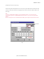
② Select "1. MR DUTY ADJUSTMENT" in the menu of the AF-S VR105 inspection program.
③ The confirmation screen for writing the fixed values in EEPROM appears. Select the appropriate item.
④ Following the instruction on the screen, rotate the MF ring slowly by hand in the direction from the infinity
to the close distance position. Make sure that the waveform on the oscilloscope has duty 50% and stop the
MF ring at the close distance-end.
CH1=5V
DC 10:1
CH2=5V
DC 10:1
5ms/div
NORM 200KS/s
● Setting of oscilloscope
V/Div(CH1)
:5V
V/Div(CH2)
:5V
Coupling
:DC
Time/Div
:5 m Sec
Trigger Mode
:NORMAL
Trigger Coupling
:DC
Trigger Source
:CH 1
Trigger Position
:-4 div
Trigger Type
:EDGE
Trigger Level
:2.5 V
⑤ Following the instruction on the screen, rotate the MF ring slowly by hand in the direction from the close
distance to the infinity position. Make sure that the waveform on the oscilloscope has duty 50% and stop
the MF ring at the infinity-end.
Note:In case the waveform from infinity to close distance position or vice versa does not have duty 50%,
repeat "INSPECTION AND ADJUSTMENT OF THE MR ENCODER OUTPUT WAVEFORM" on
Page A9.
H
Sandard H:L= 100:150 ~ 150:100(50% ±10.0%)
L
- A33 ・ AF-S VR MC 105/2.8G -
JAA63051-R.3689.A
Adjustment of Driving frequency and Motor control
● In case of replacing the main PCB, SWM unit and MR encoder unit, be sure to make adjustments.
① The method of connection of the rated voltage power supply and measuring tools is the same as
"ADJUSTMENT OF MR DUTY".
② Make sure that the electric current and voltage of the rated voltage power supply are set to the set values
on the PC screen.
③ Turn the rated voltage power supply ON.
④ Select "2. ADJUSTMENT FOR DRIVING FREQUENCY & MOTOR CONTROL" in the menu of the
AF-S VR105 inspection program. The lens automatically starts the driving of scanning.
Fig.2
Fig.1
⑤ When "Fig. 1" screen is displayed, and if "OK" is clicked, "drive frequency and the motor control
adjustment" is completed. If "Adjustment could not be executed." of "Fig. 2" is displayed, make
readjustment.
Even after the readjustment, if "Fig. 2" screen is still displayed, adjust the "MR duty" again and perform
"drive frequency and the motor control adjustment" again.
However, after all the above, if the adjustment is still impossible, the SWM unit, the fixed tube unit, GMR
tape unit, or MR head unit may be defective.
- A34 ・ AF-S VR MC 105/2.8G -
JAA63051-R.3689.A
Inspection of Lens operations
Check the lens operations by using a personal computer after assembling.
○ Check by personal computer
● Check by the following considerations:
1. MR encoder operations
・Drive the scanning of lens and check the total number of pulses.
・In case the MR head of the MR encoder and the magnetic tape are misaligned, the number of pulses
becomes out of standard.
2. Lens-servo stop accuracy
・Check the number of overrun/underrun pulses (deviation of the stop position from the target position) per
the specified lens driving.
・In case the irregularity of mechanical operations does not take place in the focus ring driving unit, the
underrun tends to occur if it is heavy in the cam ring rotation of the MR encoder, while the overrun tends
to occur if it is light in its rotation of the MR encoder.
3. Lens-servo time
・Check the servo time (from starting and stopping the servo) when driving the specified lens by using the
oscilloscope.
・In case the irregularity of mechanical operations does not take place in the focus ring driving unit, the
servo-time tends to be long if it is heavy in the cam ring rotation of the MR encoder, while the servo-time
tends to be short if it is light in its rotation of the MR encoder.
4. Switches and lenses
・Check the ON/OFF operations of switches and the operating condition of the distance encoder.
● After inspections
1. When the MR encoder operations are not up to the standard:
Readjust the MR duty. (ref. Page A33.)
In case the pulse is not up to the standard, adjust the output waveform of the MR encoder again.
(ref. Page A9.)
(Misdescription)
In case the pulse meets the standard, replace the cam ring unit fixed-tube unit or the mechanical
(Addition)
parts that make the focus ring drive.
2. When the lens-servo stop accuracy is not up to the standard:
Check the output waveform of the MR encoder. If it is normal, replace the fix-tube unit or the
mechanical parts that make the focus ring drive.
(Addition)
3. When the lens-servo time is not up to the standard:
Readjust the driving frequency and motor control.
In case the lens-servo time is not up to the standard even after the readjustment, replace the fix-tube
unit or the mechanical parts that make the focus ring drive.
(Addition)
4. When switches do not work properly:
Check the wiring state of the troubled switch or replace it.
Changed page
×4
- A35 ・ AF-S VR MC 105/2.8G -
May. 26. 2006
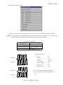
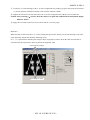
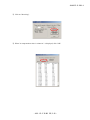
●AF-S VR 105 inspection program
JAA63051-R.3689.A
(1) Menu screen
1
2
3
4
5
6
7
・Menu items
The items 1 and 2 are used for adjustments.
The item 3 is used for reading and writing EEPROM DATA.
"Store & Restore the EEPROM DATA" on the sub-menu 5 is the item by which all the data of
EEPROM-valuesin the lens can be backed up or the backed-up files can be written in the lens.
(This is not used for regular repairs.)
The items 4~7 are used for inspections.
・Selection items
After selecting items screens appear, such as the lens selection, the
focal length selection, the voltage setting, the inspection mode start.
The screens depend on the items. Follow the instructions of the personal computer.
・Initial driving
Drive scanning several times and stop at infinity-end.
- A36 ・ AF-S VR MC 105/2.8G -
JAA63051-R.3689.A
(2) Inspection of MR encoder operations
Caution:If the MF ring is rotated while the lens scanning is driven, the pulse shows an abnormal value.
Do NOT touch the MF ring during operations.
Make inspections at the 5 positions as below.
(Lens position in inspecting)
Lens inclination
Position of index window
Horizontal
Up, right and left
Front lens group 90° upward
Front lens group 90° downward
When the inspection ends, the result of the next page appears.
- A37 ・ AF-S VR MC 105/2.8G -
JAA63051-R.3689.A
The difference in pulse before and after the inspection must be within the standard.
< Standard > Total pulses : 12332 ± 300 PLUSE(S)
- A38 ・ AF-S VR MC 105/2.8G -
JAA63051-R.3689.A
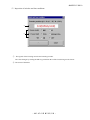
(3) Inspection of lens-servo stop accuracy
If the lens stops while inspecting the lens-servo stop accuracy, input a figure between 0-1000 for the delay
time (msec: millisecond), which prevents stopping the lens, into the entry field of "DELAY-TIME" of the
below Fig.3,
Note:
The value of "ADUST DELAY-TIME" is set by the adjustment software. So, if the lens does not
stop during the inspection of "LENS DRIVING STOP ACCURACY", any value can be input without
problem.
However, the larger the value of "ADJUST DELAY-TIME" gets, the longer the inspection time becomes.
entry field
Fig.3
- A39 ・ AF-S VR MC 105/2.8G -
JAA63051-R.3689.A
①
②
③
④
Caution:If the MF ring is rotated while the lens scanning is driven, the pulse shows an abnormal value. Do
NOT touch the MF ring during operations.
During the lens driving, the above screen is displayed. Make inspections at the 5 positions as below.
(Lens position in inspecting)
Lens inclination
Position of index window
Horizontal
Up, right and left
Front lens group 90° upward
Front lens group 90° downward
The number of overrun/underrun pulses must be within the standards after the 5 lens back-and forth driving
motions ("5/5TIME (S)." in [1] of the display).
Standard RATIO (1) is 40% or less for Df1~Df6.
(Occurrence ratio of 5~12 pulses)
RATIO (2) is 10% or less for Df1~Df6.
(Occurrence ratio of 9~12 pulses)
Occurrence of 13 or more pulses is zero for Df1~Df6.
(Only one occurrence indicates malfunction.)
※ "Df1~Df6" shows the lens driving amount.
- A40 ・ AF-S VR MC 105/2.8G -
② of the screen
③ of the screen
④ of the screen
JAA63051-R.3689.A
(4) Inspection of lens-servo time
Select the servo driving amount respectively. Each lens-servo drive time must be within the standard.
Caution:If the MF ring is rotated during inspections, the waveform shows an abnormal value. Do NOT touch
the MF ring during inspections. Make inspections at the 5 positions as below.
(Lens position in inspecting)
Lens inclination
Position of index window
Horizontal
Up, right and left
Front lens group 90° upward
Front lens group 90° downward
●Oscilloscope setting
E terminal
H terminal
Servo driving time
V/Div
:5V
Coupling
:DC
Time/Div
:20 m Sec
Trigger Mode
:SGL (S)
Trigger Coupling
:DC
Trigger Source
:CH1
Trigger Position
E terminal
:-4 div
※ The waveforms of E and H terminals have the
forms for going up for start and going down for
start.
H terminal
Servo driving time
- A41 ・ AF-S VR MC 105/2.8G -
JAA63051-R.3689.A
(5) Inspection of switches and lens conditions
①
②
① The signals of the focusing encoder and zooming encoder.
The value changes by turning the MF ring with M or M/A of the lens driving mode selector.
② The status of Switches
- A42 ・ AF-S VR MC 105/2.8G -
JAA63051-R.3689.A
Necessary adjustment when replacing parts
Adjustments
Adjustment for MR duty
(Write fixed value, when replaced
Parts to be
replaced
Main PCB );
driving frequency; motor control
Inspection & adjustment for MR
encoder operations;
lens-servo stop accuracy;
lens-servo time; switches;
lens condition
○
○
○
○
Main PCB unit
SWM unit
VR adjustment
○
VR unit
○
Jyro unit
○
○
○
○
○
GMR unit
Fix-tube unit
- A43 ・ AF-S VR MC 105/2.8G -
○
○
JAA63051-R.3689.A
Lens Alignment
Note:
This adjustment is required when the front (1-1st) and/or the rear (5th) lens group(s) are/is removed.
(1) Preparation of Lens optical alignment equipment
※ For this AF-S VR MC105/2.8G, the lens alignment equipment (for center and periphery) cannot be used in
terms of accuracy. Instead, the point tester and the following devices are used.
Chart-shooting device for Lens alignment
Lens alignment chart (J19128)
embedded in cardbaords
Lens alignment equipment slide rail
(J19129)
★ New tool
Retaining ring
Knob×4
Knob×4
Retaining ring
Body
Index for
mounting
Body
Lens holder
Lens holder
1-1st lens-G alignment tool ( ★ J11327)
5th lens -G alignment tool ( ★ J11328)
- A44 ・ AF-S VR MC 105/2.8G -
JAA63051-R.3689.A
★ New tool
(2) 5th lens-group alignment (for center)
① Mount the rear cover ring temporarily, and fix it so that the aperture becomes full open.
② Set the focus ring to "∞", and mount it on the point tester.
③ Check the optical axis. If the result is "OK" as shown below "Fig.1", go to the next "『(3) Chart shooting
for the 1-1st lens-G alignment (for periphery)". If "NG", follow the below ④ , and make alignment for the
5th lens group.
Judgment
OK
NG
NG
Fig. 1
Point tester
④ Give the four knobs of the 5th lens-G alignment tool ( ★ J11328) about half-turn counterclockwise from the
position where the knobs are screwed completely.
⑤ Give the retaining ring of [ ★ J11328] about two-turns counterclockwise from the position where the retaining
ring is screwed completely.
Caution: If turning the retaining ring counterclockwise is not enough, the rotation becomes heavy or
impossible when the tool is mounted. In this case, turn it counterclockwise further.
⑥ Remove the rear cover ring from the lens, and mount [ ★ J11328] on the bayonet.
Index for
mounting
- A45 ・ AF-S VR MC 105/2.8G -
JAA63051-R.3689.A
★ New tool
⑦ Rotate the retaining ring until the three setscrew (#113) of the 5th lens group can be seen.
(The slightly loosened retaining ring is acceptable at the place where the above screw can be seen.)
Retaining ring
Screw (#113)×3
Alignment screwdriver
⑧ Loosen the three screws (#113) with the alignment screwdriver.
⑨ Remove the lens mounting of the point tester.
⑩ Insert the convex portion of the retaining ring of the 5th lens-G alignment tool ( ★ J11328) into the hole of
the lens mounting of the point tester. Then set the lens. (Set the focus ring to "∞". )
Lens mounting
Point tester
- A46 ・ AF-S VR MC 105/2.8G -
Point tester
JAA63051-R.3689.A
⑪ Check the optical axis by looking through the eyepiece lens of the point tester. Rotate the knob of the 5th
lens-G alignment tool ( ★ J11328), which is set in the lens, and adjust until the optical axis becomes "OK"
(ref. Fig. 1). (ref. ⑭ for how to rotate.)
⑫ When the adjustment is completed, tighten the three screws (#113) with the alignment screwdriver, and
remove [ ★ J11328] from the lens.
⑬ Apply the screwlock to the heads of the three screws (#113).
Judgment
OK
NG
NG
Fig. 1
⑭ To operate [ ★ J11328], hold the knobs at the same time which are diagonally positioned to each other.
When the one knob is rotated and slid down towards a direction, the other knob must be rotated and slid up
towards the opposite direction. Adjust the position of the lens. (ref. below A ~ D)
A. Lens moves diagonally towards upper-right direction
B. Lens moves diagonally towards lower-left direction
C. Lens moves diagonally towards upper-left direction
D. Lens moves diagonally towards lower-right direction
- A47 ・ AF-S VR MC 105/2.8G -
JAA63051-R.3689.A
(3) Chart shooting for the 1-1st lens-G alignment (for periphery)
(Addition)
① Prepare a camera (D100). Set the shutter speed to "M1/80" with fullaperture and the focus mode to "S".
On the shooting menu, set "Image Quality" mode to "RAW", "WB" to "Preset" and "ISO" to "200".
(Addition)Turn
on the vibration reduction SW of lens.
② Set up the camera (D100) on a tripod on the slide rail. Set the indication pointer of the tripod to 30 cm.
30 cm
③ Set the alignment chart (J19128) as shown below.
Alignment chart
(J19128)
Focal plane mark of camera
Magnifications: 30
3 m 15± 1 cm
Rail tool
Front
Back
Changed page
×2
- A48 ・ AF-S VR MC 105/2.8G -
June. 20. 2006
JAA63051-R.3689.A
④ Turn the power of viewers (5 pcs.) to ON.
(Note: If the batteries of viewers are exhausted with decreased brightness, the shooting data cannot
be obtained correctly.)
Viewer× 5 pcs.
Front
Back
⑤ Fit the lens to be examined in the camera (D100).
⑥ By looking through the viewfinder, adjust the height and tilt to make the chart fill the entire finder field
frame.
⑦ Adjust the tilt of the slide rail to make the three chart lines position in the center of the viewfinder, when the
tripod is slid all the way to the front and back.
⑧ Connect the PC and camera via USB cable. Rotate and set the focus ring of the lens to "∞". (Camera setting:
Mass Storage)
⑨ Start the adjustment software (LWM.exe).
⑩ "Lens Select" window opens. Select "AFS VR 105/2.8G", then click "OK" button.
⑪ Click the "Reset all log" button.
- A49 ・ AF-S VR MC 105/2.8G -
JAA63051-R.3689.A
⑫ Set the indication pointer of the tripod to 30 cm.
⑬ Darken the room.
⑭ Click "Focusing" button. AF is activated to focus and the shutter is released.
⑮
Set the focus mode of the camera (D100) to "M".
⑯ Slide the tripod to the front by 18 ± 0.1 cm.
⑰ Click the "measurement" button of the adjustment software.
⑱ When the shutter of the camera is released, slide the tripod to the back by 6 ± 0.1 cm and make a
remeasurement.
⑲ Again, slide the tripod to the back by 6 ± 0.1 cm and make a remeasurement.
Repeat this operation four more times, totalling in seven measurements.
(The total sliding distance is 36 cm.)
- A50 ・ AF-S VR MC 105/2.8G -
JAA63051-R.3689.A
Note 1: When the below warning is given, there may be some defects in the brightness of the
viewers and/or parallelism of the chart and camera, etc. So correct the above and make a
remeasurement.
Note 2: When the below warning is given, recheck that the Quality mode of the camera is set to RAW.
- A51 ・ AF-S VR MC 105/2.8G -
JAA63051-R.3689.A
⑳ After the seven measurements, point the cursor to the confirmation screen of the software. Click it three
times, and
if "END" is displayed on the Information, the lens optical alignment is completed.
If "END" is NOT displayed (Adjust peripheral alignment by J19125 With below value), go to the next "(4)
1-1st lens-group alignment (for periphery)" to readjust.
J11327 (Misdescription)
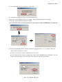
Confirmation screen
Information display
Changed page
×1
- A52 ・ AF-S VR MC 105/2.8G -
May. 26. 2006
JAA63051-R.3689.A
(4) 1-1st lens-group alignment (for periphery)
Caution: As for products lens, the screwlock is applied around four screws (#142) and the 1-1st lens
group. So wipe the screwlock as far as possible with alcohol, etc, then work on the lens
alignment.
① Give the four knobs of the 1-1st lens-G alignment tool ( ★ J11327) about half-turn counterclockwise from the
position where the knobs are screwed completely.
② Give the retaining ring of [ ★ J11327] about two-turns counterclockwise from the position where the retaining
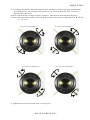
ring is screwed completely.
③ Screw [ ★ J11327] all the way in the filter ring of the lens. Then turn it counterclockwise until the four knobs
of [ ★ J11327] are positioned like "X" when viewed from the front. (ref. Pic. 1)
Filter ring
Retaining ring
Knob×4
Lens index
Pic. 1
Lens holder
1-1st lens-G
1-1st lens-G alignment tool(★ J11327)
④ Rotate the retaining ring until the four setscrews (#142) of the 1-1st lens group can be seen.
[The slightly loosened retaining ring is acceptable at the place where the four screws (#142) can be seen.]
Alignment screwdriver
Screw (#142)×4
⑤ Screw each four knobs of [ ★ J11327] evenly, and stop screwing until they touch the lens holder.
⑥ Loosen the four screws (#142) with the alignment screwdriver.
- A53 ・ AF-S VR MC 105/2.8G -
JAA63051-R.3689.A
⑦ According to the result of "Information display" of the adjustment software, which was performed in the
chart shooting of (3), select from the below pictures A ~ D, and rotate the knobs of the 1-1st lens-G
alignment tool ( ★ J11327).
(At first, rotate the knobs at an angle of approx. 45 degrees. Then shoot the chart and check the image.)
Caution)The method of the rotation is the same as the operation of the 5th lens-G alignment tool ( ★ J11328)
[i.e. ⑭ of (2)].
A. In case of "X directions:-1"
C. In case of "Y directions:+1"
B. In case of "X directions:+1"
D. In case of "Y directions:-1"
⑧ Tighten the four set screws (#142) of the 1-1st lens group.
- A54 ・ AF-S VR MC 105/2.8G -
JAA63051-R.3689.A
⑨ Perform [(3) Chart shooting for the 1-1st lens-G alignment (for periphery)] again, and repeat the procedure
(3) and (4) until the information display of the software indicates "END".
⑩ Tighten the four screws (#142) and remove the 1-1st lens-G alignment tool ( ★ J11327) from the lens.
Caution: After removing [ ★ J11327], shoot the chart of (3) again and confirm that the information display
indicates "END".
⑪ Apply the screwlock on the four screws (#142) and the 1-1st lens group.
Reference:
When the chart is shot in the above ⑨ , before sliding the tripod to the front by 18 cm and shooting seven times,
click "Focusing" button and check the following screen.
If ⑥ - ⑧ is performed so that the point images’ shape of periphery becomes about the same and also that of
center becomes about the same, this will shorten the alignment work.
Point image of periphery
Point image of center
- A55 ・ AF-S VR MC 105/2.8G -
JAA63051-R.3689.A
How to create Setting board of "Lens alignment chart" and "Viewer"
1. Summary
1-1: In order to get necessary data for lens alignment, this board is created to use for setting a special chart and light
viewers (for chart illumination), while taking pictures of the special chart with a digital camera.
2. Preparation
2-1:Prepare a board (760 x 880 x 20 mm) or 2 package cardboard boxes (size 2.33).
(Note) Because you have to cut out the shape to embed light viewers, choose package cardboard boxes (size 2.33) or
material which can be easily cut. - ref. Fig. 1
3. Procedure (In this document, 2 package cardboards are used)
3-1: As for the 1st flattened cardboard box (size 2.33), check the positions for embedding the light viewers, and cut out
the shape at 5 locations (shaded parts/size 154 x 245 mm) as shown below. - ref. Fig. 2
(Note) Cutting the shape slightly smaller than the actual size of viewers makes it easier to fit the positions of viewers
tightly.
3-2:Put the 2nd flattened cardboard box (size 2.33) and the above cut-out 1st cardboard together as one, and fix them by
taping at 4 sides. - ref. Fig. 3
3-3:Then as for the 2nd flattened cardboard box, cut out the shape again by matching the cut-out size of 3-1 for each
viewer. - ref. Fig. 4
3-4:Reinforce the edges of cut-out parts with tape.
(Note) To prevent viewers falling off, secure them with tape around the edges. - ref. Fig. 5
3.5: Blacken around the setting board (with black spray, etc).
880
105
154
145
245
380
100
To prevent viewers falling off,
105
380
245
attach Velcro tape on the back of
190
500
the cardboard. Inthis document,
2mm-width hook and loop
fastener is used.
190
4. Prevent Viewers from falling off (In this document, 2-mm width Velcro tape is used.)
4-1: As shown above, when viewers are embedded, secure them with square pieces of Velcro tape (hook and loop
fastener) on the back of the cardboard to prevent viewers falling off.
- A56 ・ AF-S VR MC 105/2.8G -
JAA63051-R.3689.A
(Fig. 1- Prepare two package cardboard boxes,
and flatten them as below.)
(Fig. 2 - As for the 1st flattened cardboard box, cut out the
<154 x 245 mm sized> shape at 5 locations.)
(Fig. 3- Package cardboard boxes)
Put the 2nd flattened cardboard boxe and the1st
cut-out cardboard together as one as shown
below.
(Fig. 4- As for the 2nd flattened cardboard box, cut
out the shape in the same way as Fig.2. Allcardboards
are cut out as below.
Cut out by matching the size of the 1st cutting.
Fix them by taping at 4 sides.
����
����
(Fig. 5- Light viewers are embedded.)
(Fig. 6- Setting board is blackened with the chart being
attached.)
To prevent viewers falling
off, secure the viewers with
tape around the sdges.
- A57 ・ AF-S VR MC 105/2.8G -
JAA63051-R.3689.A
F.F.D (flange focal distance)/Backfocus Adjustment
① Take out the screw (#132) of the change-SW
unit, and slacken the change-SW.
#132
★:New tool
② Set the focus ring to the infinity (∞).
③ Insert the infinity positioning pin ( ★ J11319) into the
"A" hole.
"A" hole
Change-SW
Infinity positioning pin
★ J11319
④ Insert a suitably-sized cut heavy paper or plastic, etc, into the 3.1-aperture lever so that the aperture becomes
full open.
⑤ Set the lens on the lens adapter for focus tester, and measure "M.B.f" value by the back focus collimator LT500S (J19002).
⑥ In case the result is out of standard, remove the bayonet mount and the washer (#176).
⑦ For a difference between the value ( ⑤ ) and the standard value, adjust the thickness by selecting the washers
(#176: selected from A ~ M).
(In the difference is positive, increase the washers. If it is negative, decrease the washers.)
Standard: 0±0.05 mm
⑧ In case the result is within standard, confirm the "∞" alignment by the horizontal-type collimator.
Standard: Center of (∞)-mark ± 2/3
±2/3
Caution:
In case the back focus collimator LT-500S (J19002) is not available, use a horizontal-type collimator to confirm
"∞" alignment, and select the above washers for the adjustment.
- A58 ・ AF-S VR MC 105/2.8G -
JAA63051-R.3689.A
VR adjustment
When making the VR adjustment, refer to the "Instruction Manual" that is attached to the VR lens adjustment
equipment (J15380).
!
WARNING
●This
equipment uses the laser beam.
Do not look at the laser beam directly or
through the laser beam window.
Preparation
① Set up the VR lens adjustment equipment (J15380) as shown below.
② Connect the personal computer to the equipment and start the PC.
③ Mount the lens on the equipment. Set the infinity (∞) mark of the focus ring to the index.
Refer to the next page for "Procedure for mounting the lens".
RS232C cable
PC
Laser beam window
Laser beam
Power switch
"SERVO" switch
VR lens adjustment equipment
(J15380)
"VIBRATION" switch
Notes: Keep the approx. 5-m distance from the laser beam window to the radiated surface.
Do not block the light path of the laser beam.
- A59 ・ AF-S VR MC 105/2.8G -
JAA63051-R.3689.A
Procedure for mounting the lens
1. Mount the lens on the equipment and move the lens retainer stand in the direction of the arrow.
Lens retainer stand
2. Move the lens retainer stand to the position as shown below and fix it by tightening the clamp.
Clamp
- A60 ・ AF-S VR MC 105/2.8G -
JAA63051-R.3689.A
④ Turn the VR lens adjustment equipment (J15380) ON and start the adjustment software.
⑤ Point the cursor to "AF-S VR MICRO 105/2.8G" on the Lens selection screen and click it.
※ If the below message appears, reset the zoom ring by referring to "Procedure for mounting the lens" on the
previous page. Then click "OK" button.
The focus ring is automatically set.
Note: Do not change the lens settings (zoom ring), until the adjustment is completed and go back to the Lens
selection screen.
If the setting position changes during the adjustment, the correct adjustment value cannot be obtained.
- A61 ・ AF-S VR MC 105/2.8G -
JAA63051-R.3689.A
Vibration Reduction mode switch inspection
① Point the cursor to the check box before "VR Mode Switch Inspection" and click it.
② Point the cursor to the "Execute" button and click it.
③ "VR Mode Switch Inspection" screen appears.
- A62 ・ AF-S VR MC 105/2.8G -
JAA63051-R.3689.A
④ The position of VR mode switch is indicated.
Selecting the VR mode switch indicates the current position in the real time.
VR mode switch
⑤ When completing the VR mode switch inspection, point the cursor to "Exit" button and click it to exit the
inspection screen.
- A63 ・ AF-S VR MC 105/2.8G -
JAA63051-R.3689.A
VR lens position adjustment
① Point the cursor to the check box before "VR Lens Position Adjustment" and click it.
② Point the cursor to "Execute" button and click it.
③ The left message appears.
Turn the VR mode switch of the lens to ON, then
point the cursor to "OK" button and click it.
・VCM Polarity Adjustment (Automatic control)
Get the polarity of the VCM (Voice Coil Motor) and write it in EEPROM as the compensation value.
During the adjustment, the message appears to confirm the lens position of angle (0 or 90 degrees).
Therefore, set the lens to the position and click "OK" button.
When "OK" is shown on the execution screen, point the cursor to "Next" button and click it.
- A64 ・ AF-S VR MC 105/2.8G -
・Gamma and Shift Adjustment (Automatic control)
JAA63051-R.3689.A
Adjust the inclination and control center position based on the position sensor output of the VR unit.
During the adjustment, the message appears to confirm the lens position of angle (0 or 90 degrees).
Therefore, set the lens to the position and click "OK" button.
When "OK" is shown on the execution screen, point the cursor to "Next" button and click it.
・Electromagnetic Lock Center Position Adjustment (Automatic control)
Adjust the electromagnetic lock center position.
During the adjustment, the message appears to confirm the lens position of angle (0 or 90 degrees).
Therefore, set the lens to the position and click "OK" button.
When "OK" is shown on the execution screen, point the cursor to "Next" button and click it.
The inspection mode starts automatically. When the following is displayed on the execution screen, point
the cursor to "Next" button and click it.
- A65 ・ AF-S VR MC 105/2.8G -
JAA63051-R.3689.A
・Mechanical Lock Inspection
When the mechanical lock inspection is made, write the inspection result data as the adjustment value.
The below 1 and 2 screens are displayed alternately, so turn the VR switch to ON/OFF 5 times for the lens
position 0 and 90 degrees respectively, according to the indicated instructions.
Screen 2.
Screen 1.
When "OK" is shown on the execution screen, point the cursor to "Next" button and click it.
・When the message "Finished rewriting checksum value" is
shown, click "OK" button.
Turn the VR switch to OFF according to the message, and click
"OK" button to exit the adjustment screen.
Note:
If "NG" is shown during the adjustment, click "Next" button to
exit the inspection mode. Go back to the Lens Selection screen
after rewriting the checksum value, and make the adjustment
again.
If "NG" appears even after making the adjustment a few times,
the VR unit, the gyro PCB, and the main FPC, etc should be
defective.
- A66 ・ AF-S VR MC 105/2.8G -
JAA63051-R.3689.A
VR Gyro Adjustment
① Point the cursor to the check box before "VR Gyro Adjustment", and click it.
② Point the cursor to "Execute" button, and click it.
③ The left message appears.
Set "Frequency" of "Telephoto" to 5.0 Hz
in the settings of the VR lens adjustment
equipment (J15380).
Viewed from above
Laser switch knob
Nut
④ Loosen the laser switch nut of the VR lens
adjustment equipment (J15380), and rotate
the knob in the arrow direction to irradiate
laser light.
Laser pointer
- A67 ・ AF-S VR MC 105/2.8G -
JAA63051-R.3689.A
"VIBRATION" switch
"SERVO" switch
⑤ Press "ON" button for "SERVO" switch and
press "START" for "VIBRATION" switch
of the VR lens adjustment equipment
(J15380).
⑥ When the equipment starts to vibrate, measure the vibration width ( α ) of the laser beam.
α
Notes:During the above measurement, a phenomenon
occurs which causes laser spot light swinging
from side to side and up and down.
This is the movement of the VR unit control and
NOT defective.
⑦ Point the cursor to "Next" button in the
message box on the screen and click it. The
vibration reduction function starts and the
vibration width of the laser beam becomes
narrow.
- A68 ・ AF-S VR MC 105/2.8G -
JAA63051-R.3689.A
・Adjust misalignment of angle
If the angle is misaligned, the laser beam source looks
like turning around even after making the Gyro-gain
adjustment.
If the angle misalignment is detected, adjust the
misalignment by the adjustment buttons to correct it.
Note: After using the adjustment buttons, wait for
a few seconds until the vibration movement
stabilizes.
Buttons for adjusting
"Gyrog-Gain"
Buttons for adjusting
"Angle misalignment"
・Gyro-Gain Adjustment
Adjust the vibration width by the buttons for Gyro-gain adjustment so that the measured vibration width of
the laser beam becomes 1/5 or less of the maximum width ( α ).
α
Standard:
Fifth part (1/5) or less of the vibration width ( α )
Note: The laser beam vibrates widely again after
passing the peak section of the minimum value.
Peak zone of the minimum
value of the vibration width
- A69 ・ AF-S VR MC 105/2.8G -
JAA63051-R.3689.A
《Ref.》
(Revision) 18mm
・The laser spot beam travels 5-m ahead, irradiating with spot of approx. 5 mm in diameter.
(Revision)
① The vibration width is adjusted at the center of
the laser spot. First, measure the whole vibration
width.
18mm
Approx. 5 mm
(Revision) (Revision)②
5.4mm
45 mm
23.4mm
Subtract the top and bottom radial parts (shaded
areas) of the laser spots from the measured whole
vibration width.
(Revision)
27mm
40 mm
8 mm
13 mm
e.g.)
When the vibration width as a whole is "approx.
45 mm",
Vibration width of center is:
45 - (2.5 + 2.5) = 40 mm.
(Revision) 45-(9+9)=27mm
(Revision)
Standard figure after the gyro-gain adjustment
40 × 1/5 = 8 mm (Vibration width of center)
27×1/5=5.4mm
(Revision)
Vibration width as a whole is:
8+ (2.5+2.5) = 13 mm.
5.4+(9+9)=23.4mm
・How to obtain the minimum value of the vibration width
① Measure the vibration width while changing the adjustment value that is set every 0.02-Step as shown
below.
② The peak zone of the minimum vibration width can be obtained by the actual measured value.
③ The center of the peak zone becomes the adjustment value.
Gyro Gain
Adjustment
Value
・ ・ Vibration width
Actual measured
value
・
・
0.90
0.92
0.94
0.96
0.98
1.00
1.02
1.04
1.06
1.08
1.10
15.5 mm
14.5 mm
14.0 mm
13.5 mm
13.0 mm
13.0 mm
13.0 mm
13.5 mm
14.0 mm
14.5 mm
15.0 mm
・ ・
・ ・
Note: Measure the vibration width in the half a millimeter (0.5 mm).
Changed page
×8
- A70 ・ AF-S VR MC 105/2.8G -
June. 20. 2006
JAA63051-R.3689.A
・ Press "STOP" button of VIBRATION switch of the VR
adjustment equipment to stop vibrations.
・ Rotate the lens through 90° in the direction indicated by the
arrow, then press “START” button of VIBRATION switch
to start vibrations.
・ At the 90° position, adjust the angle misalignment and
make gyro-gain adjustment.
Note: When adjusting the lens at the 90 ° position, adjust by
the buttons for the adjustment at 90 ° position as shown
below.
Buttons for adjustment
at 90 ° position
・After the adjustment, click "Rewrite" button to write the adjustment value in EEPROM in the lens.
・Then, click "EXIT" button to exit the adjustment mode.
Note: If clicking "EXIT" button without clicking "Rewrite" button, the adjustment value is not recorded
and the adjustment details are not written.
・Click "Quit" button on the adjustment items screen to go back to the Lens selection screen.
Note: Do NOT remove the lens or turn OFF the VR lens adjustment equipment until going back to the
Lens selection screen. Otherwise, troubles may occur such as incorrect recording of the adjustment value
due to blocked communications, etc..
- A71 ・ AF-S VR MC 105/2.8G -
JAA63051-R.3689.A
Criteria for VR performance
Before making the VR adjustment of defective products by using the equipment, refer to the following.
Check 1
Mount the lens on the
appropriate body
Repeat half-pressing ON/OFF
of the shutter release button
・Set the VR mode to "ON".
・Repeat pressing ON/OFF of the shutter release button a few times at
intervals of a few seconds during half-release timer.
How is the VR unit control?
・Judge from the controlling sound
Do NOT control entirely
[Cause]
① Checksum defect
② Broken wire of the VCM
(Both sides)
Do control only at the first stage
[Cause]
① Breakage of the VCM
(One side)
② Abnormal adjustment value
③ Others
③ Mode switch defect
④ Others
[Measure]
① Perform the checksum with
the equipment, then go to
the Check 1
② Confirm the breakage of the
VCM then go to Check 1
[Measure]
① Confirm the breakage of
the VCM then go to
Check 1
② Go to Check 2
③ Go to Check 2
③ Make the switch
inspection with the
equipment
④ Go to Check 2
Go on the next page "Check 2"
- A72 ・ AF-S VR MC 105/2.8G -
Do control whenever the
half-release is ON
Go to Check 2
JAA63051-R.3689.A
Check 2
Mount the lens on the
equipment (J15380)
Check the vibration width
of laser
・How much does the vibration width reduce, when the VR
mode changes from OFF to ON by the VR-gyro adjustment.
What is the reduction rate
of the vibration width?
More than 1/5
[Cause]
1/5 or less
The parts other than VR
may be defective.
① Incorrect adjustment value
② Others
[Measure]
① Make the lens position
adjustment and the VR
gyro adjustment
② The electric parts other
than VR may be
defective.
- A73 ・ AF-S VR MC 105/2.8G -
JAA63051-R.3689.A
Rear cover ring
#38×3
Rear cover ring
Front cover sheet
・ Attach the front cover sheet.
(The front cover sheet already has the adhesive
double-coated tape adhered.)
Front cover sheet
VR name plate
・ Attach the name plate.
(The name plate already has the adhesive
double-coated tape adhered.)
VR name plate
- A74 ・ AF-S VR MC 105/2.8G -
JAA63051-R.3689.A
Aberration compensation data writing adjustment
・ This adjustment uses the software which calculates the aberration compensation data according to
the feature of lens aberration and writes in EEPROM of the lens, in order to improve the accuracy of
autofocus.
Note: This adjustment is necessary when the main PCB and/or each lens part (glass, lens chamber)
is replaced or when each lens part is disassembled. Be sure to make this adjustment after
completing inspecting and adjusting the main PCB.
(1) Preparation
・ Test chart (Self-made tool: ref. Procedure for how to create it.)
・ Tripod
・ D100
・ Personal computer
・ USB cable(UC-E4)
・ Adjustment software (AFSVR105.exe:used for the lens optical alignment.)
(2) Procedure for how to create Test chart
・ Photocopy the next page and cut out 1 target chart and 5 resolution charts.
(Resolution chart)
(Target chart)
・ As shown below, put each chart in position at the specified spacings.
Note: Only in the center, put the target chart on the central resolution chart.
(+100μm)
(+50μm)
(0μm)
45mm
45mm
(-50μm)
45mm
(-100μm)
300mm
- A75 ・ AF-S VR MC 105/2.8G -
45mm
JAA63051-R.3689.A
(Target chart)
(Resolution chart)
- A76 ・ AF-S VR MC 105/2.8G -
JAA63051-R.3689.A
(3) Writing aberration compensation data
① Prepare a camera (D100). Set the "Exposure mode" to "A" for full aperture and "Focus mode" to "S".
On the shooting menu, set the "Image quality mode" to "FINE", "Image size" to"L", "WB" to "Preset",
and "ISO" to "200".
② Set up the camera (D100), in which the lens to be inspected is fit, on the tripod. and the distance between
the test chart and camera (CCD face) to 3 m15 ±2 cm.
(CCD-face position)
(Test chart)
3 m 15 ± 2 cm
③ As shown below, set the center of the focus area on the chart within viewfinder.
Target chart
Resolution chart
(Within viewfinder)
④ Connect the PC and camera via USB cable. (Camera setting: Mass storage)
⑤ Start the adjustment software (LWM.exe).
- A77 ・ AF-S VR MC 105/2.8G -
JAA63051-R.3689.A
⑥ Confirm that "AF-S VR 105/2.8G" is selected on "Lens select" screen. Click "OK".
⑦ Click the "Defocus rectify..." button.
- A78 ・ AF-S VR MC 105/2.8G -
JAA63051-R.3689.A
⑧ Click the "JPEG Shot" button.
⑨ The shutter is released after the AF operation. The shot image is automatically displayed on the PC
screen.
Scale the image to 100% and check which chart is in focus of the 5 resolution charts.
(+ 100μ m)
(- 100μ m)
(+ 50μ m)
(- 50μ m)
(0μ m)
⑩ Input the value of the focused position into the entry field.
e.g. The below is the case when " - 50μm" of the front focus side is in focus.
- A79 ・ AF-S VR MC 105/2.8G -
JAA63051-R.3689.A
⑪ Click on "Rewriting".
⑫ When "A compensation value is written in." is displayed, click "OK".
- A80 ・ AF-S VR MC 105/2.8G -
JAA63051-R.3689.A
⑬ The reconfirmation screen is displayed. Click "OK".
⑭ An hourglass is displayed on the screen, and writing starts.
The below screen is displayed after a few seconds. Turn camera OFF and turn it ON again.
Click "OK", and the adjustment software restarts.
Note: Unless the camera is turned off once, the value that was written in EEPROM is not reflected.
⑮ When the adjustment software restarts, perform the operations from ② to ⑩ again. Check that
"0μm" of the AF position is in focus.
If "0μm" is not in focus, repeat the operations from ② to ⑮ .
If it is not still in focus even after repetition, the written value in EEPROM may be abnormal. So click
"Design value Rewriting" to write the initial value, then proceed with the operations.
- A81 ・ AF-S VR MC 105/2.8G -
JAA63051-R.3689.A
Black Yellow Yellow
Red
Black Black
Red
Yellow
Black
実体配線図
WIRING DIAGRAM
Yellow
SWM-FPC
SWM Power source PCB
SWM 電源供給基板
接点 FPC
SWM ユニットへ
To SWM unit
M/A PCB
M/A 基板
Red
Contact FPC
Red
Absolute focal distance encoder FPC
絶対距離エンコーダ FPC
Black
Black
SWM 電源供給 FPC
Magic Tape
磁気テープ
Yellow
SWM Power source FPC
MR sensor FPC
MR センサー FPC
ロック
Lock
Yellow
Black
LED
Black
Gyro FPC
ジャイロ FPC
Blue
Red
ユニット基板
メイン基板
White
Unit PCB
Main PCB
LED
Red
Black
White
Focus mode
フォーカスモード
To Mount GND
マウントGNDへ
レンジリミット
Range Limit
VCM
Blue
VCM
SW 用 FPC SW FPC
Black
VR 用 FPC
VR FPC
- E1・AF-S VR MC 105/2.8G -
JAA63051-R.3689.A
外観図 Sketch drawings
- F1・AF-S VR MC 105/2.8G -
JAA63051-R.3689.A
組立図 Structure of the Lens
- F2・AF-S VR MC 105/2.8G -
JAA63051-R.3689.A
- F3・AF-S VR MC 105/2.8G -
JAA63051-R.3689.A
- F4・AF-S VR MC 105/2.8G -
JAA63051-R.3689.A
- F5・AF-S VR MC 105/2.8G -
JAA63051-R.3689.A
- F6・AF-S VR MC 105/2.8G -
JAA63051-R.3689.A
- F7・AF-S VR MC 105/2.8G -
JAA63051-R.3689.A
- F8・AF-S VR MC 105/2.8G -
JAA63051-R.3689.A
工具編 TOOLS
★:NEW TOOL
RJ 番号
RJ No.
J19002
名称
備考
NAME OF TOOL
縦型焦点面検査器 LT-500S
OTHERS
BACK FOCUS COLLIMATER LT-500S
J9001-5N
安定化電源5A
DC REGULATED POWER SUPPLY 5A
J18028
F用レンズ受け台
LENS ADAPTER FOR FOCUS TESTER
J18402
★
AF-S VR105/2.8 調整用ソフト
ADJ.FD FOR AF-S VR105/2.8 (IBM 3.5)
J18004-1
J18004用基準ゲージ
STANDARD GAUGE FOR J18004
J15306-1
AF-I通信ボックス
AF-I LENS COMMUNICATION BOX(CE)
J15307
AF-I通信アダプター
COMMUNICATION ADAPTER FOR AF-I
自作工具
J11319
★
FOR AF-S18-200
SELF-MADE TOOL
VR
AF-SVR105/2.8 無限位置出しピン
INFINITY POSITIONING PIN
J11329
AF-SVR105/2.8 無限指標工具
INFINITY INDEX TOOL
★
J18403
★
VR 調整ソフト (AF-S 105/2.8VR)
VR ADJ.FD FOR AF-S 105/2.8VR
J18404
★
自作工具
AFS105/2.8 調芯装置用調整ソフト(LWM)
ADJ.FD (LWM)FOR 105/2.8 ALIGNMENT
- T1・ AF-S VR MC 105/2.8G -
Ver.1.0
JAA63051-R.3689.A
★:NEW TOOL
RJ 番号
RJ No.
J11320
名称
NAME OF TOOL
1-2 群組込み工具
1-2rd LENS G ASSEMBLING TOOL
★
J11321
VR固定工具
VR-FIXING TOOL
★
J11322
1-1 群組込み工具
1-1ST LENS G ASSEMBLING TOOL
★
J11323
3群組込み工具
3rd LENS G ASSEMBLING TOOL
★
J11324
VR 群組込み工具
VR LENS G ASSEMBLING TOOL
★
J11325
5群組込み工具
5th LENS G ASSEMBLING TOOL
★
J11326
Xタイプスリムピンセット
X-TYPE SLIM TWEEZERS
★
J11327
1群調芯工具
1ST LENS G ALIGNMENT TOOL
★
J11328
5群調芯工具
5th LENS G ALIGNMENT TOOL
★
J11330
VRミラ - 工具
VR MIRROR TOOL
★
J11331
ミラ - 取付け工具
VR MIRROR ASSEMBLING TOOL
★
工具設定なし
RJNo.is not
available
鉛フリーはんだコテ
J5400
鉛フリー糸はんだ RMA02(M705) 0.5MMX500G
LEAD FREE SOLDERING IRON
ECO SOLDER RMA02(M705) 0.5MMX500G
- T2・ AF-S VR MC 105/2.8G -
備考
OTHERS
JAA63051-R.3689.A
★:NEW TOOL
RJ 番号
名称
備考
RJ No.
NAME OF TOOL
OTHERS
J19025
ポイントテスタ-PT-1200
POINT TESTER PT-1200
J15380-4
オートコリメータ 6D( 暗視野型 )
AUTO COLIMETER 6D FOR J15380
J19128
調芯装置用チャート
LENS ALIGNMENT CHART
J19128A
ライトビューワー(J19128 用)
LIGHT VIEWER (J19128)
J19129
調芯装置用スライドレール
LENZ ALIGNMENT EQUIP.SLIDE RAIL
工具設定なし
RJNo.is not available
オシロスコープ
I-40
AFレンズ用グリ-ス(I-40)
EDB0011
G92KA
MZ-800S
OSCILLOSCOP
GREASE FOR AF LENS
ネシ゛ロック(赤)1401C
SCREW LOCK 1401C
フロイル G92KA 20G
FLOIL (G92KA) 20G
ドライサ-フ MZ-800S
DRY SURF MZ-800S
OS-30MF
ドライサ-フ OS-30MF
DRY SERF OS-30MF(OIL BARRIER)
RR
ラバーグリース RR
RUBBER GREASE RR
GE-8
AFレンス゛用ク゛リ-スGE8
GREASE FOR AF LENS GE-8 1KG
EM-60L
モリコート 1Kg 缶
MORI COAT 1Kg can
- T3・ AF-S VR MC 105/2.8G -
廃番
discontinued
ニコンインステックより購
入可能
Possible to buy
from Nikon instech.
JAA63051-R.3689.A
Making of Self-made Tool
● To inspect and adjust the output waveform of MR encoder, it is necessary to make a self-made tool by using
the RP main PCB (IS020-426) of AF-SVR18-200. (If there is a defective main PCB after replacements/
repairs, use the defective one.)
Make a self-made tool according to the following procedure.
Use this range.
Main PCB
① Remove the mounted parts/elements (condenser,
transistor, IC, etc.) from the both faces of the
PCB within the range of the dotted lines. (See
the left.) Do not remove the connector.
Connector
(The parts/elements are not always needed to
be removed, if they are not affected by the next
cutoff or soldering.)
② Cut off the PCB along the dotted lines.
③ Solder the three wires on the pattern of
the front-side PCB.
④ Solder the one wire on the pattern of the
back-side PCB.
VCC (5.0V)
MR-A
GND
MR-B
PCB (Back)
PCB (Front)
- T4・ AF-S VR MC 105/2.8G -