1
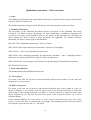
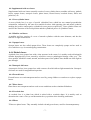
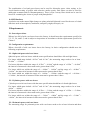
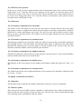
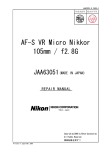
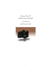
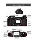
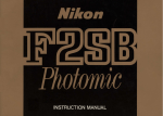
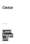
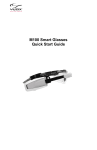
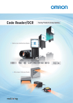
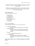
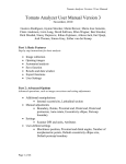
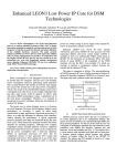
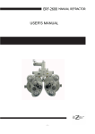
ICS 11.040.70
National Standard
of the People's Republic of China
GB 17342-200X
Replaces GB 17342-1998
Ophthalmic instrument
– Trial case lenses
(ISO 9801:1997, Ophthalmic instrument – Trial case lenses, MOD)
Draft for approval
(Draft completion date: May 2008)
Issue Date: XXXX – XX – XX
Implementation Date: XXXX – XX – XX
Issued by General Administration of Quality Supervision, Inspection and
Quarantine of the People's Republic of China
Table of Contents
Foreword...................................................................................................................... 3
1
Scope................................................................................................................ 4
2
Normative reference......................................................................................... 4
3
Terms and definitions....................................................................................... 4
4
Categorisation and application......................................................................... 6
5
Requirements.................................................................................................... 8
6
Test methods..................................................................................................... 13
7
Inspection rules................................................................................................. 14
8
Symbols, packaging, transportation and storage............................................... 15
Foreword
The entire technical content of this Standard is mandatory.
This Standard is a modified version of ISO 9801:1997, Ophthalmic instrument – Trial case lenses,
MOD.
The main technical differences between this Standard and ISO 9801:1997 are as follows:
− Clause 4 of this Standard: the categorisation and application articles and additional
descriptions for the supplemental lenses have been added;
− Article 5.2 of this Standard: the requirements for the basic configuration of trial case lenses
and the configuration of supplemental lenses have been added;
− Article 5.3 of this Standard: optical property requirements, such as: adjustments made and
provisions drawn up for the permissible errors for the cylinder power of spherical lenses;
permissible errors for the prismatic power, spherical power and cylinder power of prismatic
lenses; the classification and permissible errors for the prismatic power at the lens geometric
centres of spherical lenses and cylindrical lenses; the classification and permissible errors
for the axial position of cylindrical lenses; the classification and permissible errors for the
baselines of prismatic lenses; the technical requirements of cross-cylinder lenses, etc.;
− Article 5.4 of this Standard: structure requirements including adjustments made to the
thickness of the trial case lenses and provisions made for the structures of the supplemental
lenses;
− Article 6.3 of this Standard: testing methods for the structure of the supplemental lenses
have been added.
− Article 7.1 of this Standard: the requirements for the qualified rate of single unit spherical
lenses, cylindrical lenses and prismatic lenses, and the requirements for qualified rate of
box-full spherical lenses, cylindrical lenses and prismatic lenses have been adjusted.
Provision has been made for lens errors.
− Article 8.1 of this Standard: it is specified that all types of technical indexes of double side
lettered trial case lenses should meet optical property requirements.
This Standard is proposed by the National Institute of Metrology P.R. China.
This Standard is under the jurisdiction of the Subcommittee on Ophthalmic Optics of the National
Technical Committee on Optics and Optical Instrument under the Standardisation Administration of
China.
The main organisations which participated in the drafting of this Standard are:
National Institute of Metrology P.R. China
Shandong Institute of Metrology
Lianyungang TianNuo Optical Instrument Co. Ltd
Shanghai Solarmoon Optical Instrument Co. Ltd
The main drafters of this Standard are:
Liu Wenli, Chen Yan, Ren Hongwei, Yang Lei, Ning Lixin, Fang Zhigang.
This Standard shall come into effect on the date that GB17342-1998, Ophthalmic instrument – Trial
case lenses, is nullified.
-3-
Ophthalmic instrument – Trial case lenses
1 Scope
This Standard specifies the basic requirements for all types of trial case lenses used for detecting the
refractive defects of human eyes.
This Standard applies to all types of the full aperture and reduced aperture trial case lenses.
2 Normative References
The provisions of the following documents become provisions of this Standard after being
referenced. For dated reference documents, all later amendments (excluding corrigenda) and
versions do not apply to this Standard; however, the parties to the agreement are encouraged to
study whether the latest versions of these documents are applicable. For undated reference
documents, the latest versions apply to this Standard.
ISO 9801-1997, Ophthalmic instruments – Trial case lenses
GB/T 10050-1988, Optics and optical instruments - Reference wavelengths
GB/T 10810.1 – 2005, Uncut finished spectacle lenses
GB/T 2828.1-2003, Sampling procedures for inspection by attributes – Part 1: Sampling schemes
indexed by acceptance quality limit (AQL) for lot-by-lot inspection
GB/T 15464-1995, General purpose specification for the packaging of instrumentation products
JJG 580-2005, Focimeters
3 Terms and definitions
This Standard adopts the definitions listed below.
3.1 Vertex power
Use metre as the unit, the reciprocal of the measured paraxial vertex length of a lens. One lens
consists of two vertex powers.
3.2 Back-vertex power
Use metre as the unit, the reciprocal of the measured paraxial back vertex length of a lens. As
shown in Diagram 1, the distance from the back vertex to the paraxial back focus is called the
paraxial back vertex length, indicated by symbol l'f, and its reciprocal is called the back-vertex
power, indicated by 1/l'f. The unit for back-vertex power is the reciprocal of metre (m-1), and is
called the dioptre.
Under normal conditions, the vertex power of a lens refers to its back-vertex power. The vertex
power of a trial case lens is related to the wavelength. This Standard specifies that the selected
wavelength is green mercury line, λe = 546.07nm.
-4-
F – Object focal point
F' – Image focal point
H'- Image principal point
f – Object focal length
If – Front vertex focal length
H – Object principal point
f' – Image focal length
I'f – Back vertex focal length.
Diagram 1 Schematic diagram of back vertex focal length of lenses
3.3 Prismatic power
The deviation metric generated by the light ray went through a specific point (usually the centre) of
the lens. The unit for prismatic power is centimetre per metre (cm/m) and the unit name is prismatic
dioptre.
Diagram 2 Schematic diagram of prismatic
3.4 Trial case lenses
A trial case lens refers to a lens which is fitted in a lens holder for the purpose of determining the
refractive defects of human eyes.
3.5 Full-aperture trial case lenses
A full-aperture trial case lens refers to a lens which has the maximum limit of clear aperture and is
fitted in a protection holder with a wall thickness of 1 mm.
-5-
3.6 Reduced-aperture trial case lenses
A reduced-aperture trial case lens refers to a lens with a clear aperture which is visibly smaller than
the external diameter of its holder and is evidently thin.
3.7 Additive-power trial case lenses
This refers to trial case lenses which are combined with spherical lenses, cylindrical lenses, or a
combination of spherical lenses and cylindrical lenses. The back-vertex power measured from its
final plane is equal to the combination of the nominal values of the meridian lines of all trial case
lenses which are in the frames.
3.8 Spherical-power trial case lenses
This refers to trial case lenses which can make the parallel light beams of the paraxial meet at the
same point.
3.9 Cylinder-power trial case lenses
This refers to trial case lenses which consist of two main vertex powers and can make the parallel
light beams of the paraxial meet on two separate but mutually orthogonal intersection lines.
The vertex power of one principal meridian of any cylinder-power trial case lens is zero. The
cylindrical power means the vertex power of the principal meridian where its vertex power is not
zero.
4 Categorisation and application
In practical applications, the combination of all types of trial case lenses is called a trial lens set. A
trial lens set is a type of ophthalmology measuring instrument used in ophthalmology departments
in hospitals and opticians to detect the refractive state and strabismus, or amblyopia and other visual
functions of the human eye.
Trial case lenses mainly consist of positive and negative spherical-power trial case lenses, positive
and negative cylinder-power trial case lenses and prismatic-power trial case lenses, as well as
supplemental trial case lenses etc. Trial case lenses can be divided into categories as below:
4.1 Spherical-power trial case lenses
A spherical-power trial case lens consists of a positive and a negative spherical-power trial case
lens. Positive spherical-power trial case lenses are used for the detection of hyperopia and
presbyopia in the human eye; negative spherical-power trial case lenses are used for the detection of
myopia.
4.2 Cylinder-power trial case lenses
A cylinder-power trial case lens consists of a positive and a negative cylinder-power trial case lens.
Positive cylinder-power trial case lenses are used for the detection of the hyperopia, presbyopia and
astigmatism in the human eye; negative cylinder-power trial case lenses are used for the detection
of the myopia and astigmatism in humans.
4.3 Prismatic-power trial case lenses
Used for the detection of the strabismus and heterophoria in the human eye.
-6-
4.4 Supplemental trial case lenses
Supplemental trial case lenses normally consist of cross-cylinder lenses, maddox rod lenses, pinhole
lenses, opaque lenses, stenopeic lenses, plano lenses, frosted lenses, crosshair lenses, filters and
polarisers, etc.
4.4.1 Cross-cylinder lenses
A cross-cylinder lens is a type of special cylindrical lens, which has two mutual perpendicular
orientations, indicated by the same two numerical values with opposing plus and minus symbols,
marking the positive and negative cylindrical vertex powers respectively. Cross-cylinder lenses are
used for the detection of the axial position and the cylindrical power of cylindrical lenses.
4.4.2 Maddox rod lenses
A maddox rod lens consists of a row of smooth cylinders with the same diameter, and has the
function of light transmission.
4.4.3 Opaque lenses
Opaque lenses are also called opaque discs. These lenses are completely opaque and are used to
cover whichever eye is not undergoing examination.
4.4.4 Pinhole lenses
A pinhole lens is an opaque lens with a clear aperture in the centre. It is mainly used to distinguish
whether hypophysial eyes are caused by refractive errors or pathological change of the eyes. The
clear aperture should be round, smooth, and other parts of the pinhole lens should not allow light to
pass through.
4.4.5 Stenopeic slit lenses
A stenopeic slit lens is an opaque lens with a narrow slit which allows light transmission. Stenopeic
slit lenses are used for astigmatism inspection.
4.4.6 Frosted lenses
Frosted lenses are semi-transparent and are used by young children or outdoors to replace opaque
lenses.
4.4.7 Plano lenses
Plano lenses are transparent and are used to test conditions such as simulated blindness.
4.4.8 Crosshair lens
A crosshair lens is a plano lens which is etched with a crosshair shape. It is mainly used to
determine the centre of an eye and determine the eye position when checking strabismus.
4.4.9 Filters
"Filters are plano lenses. They normally include red and green lenses, used for chromatoptometry.
-7-
The combination of red and green lenses can be used for binocular stereo vision testing, or for
visual function testing of people with refractive media opacity. Red filters can also be used for
amblyopia treatment and for chromatoptometry. There is also a tawny filter which can be used in
lenses for examining the vision of people with photophobia."
4.4.10 Polarisers
A polariser can make natural light changes to plane polarised light and is used for the tests of visual
functions such as heterophoria, strabismus, unequal eyesight, stereopsis, etc.
5 Requirements
5.1 General provisions
When a box-full of trial case lenses leaves the factory, it should meet the requirements specified in
5.2, 5.3, 5.4, and 5.5, and is subject to inspections in accordance with the requirements specified in
Clause 6.
5.2 Configuration requirements
When a box-full of trial case lenses leaves the factory, its basic configuration should meet the
following requirements.
5.2.1 Spherical-power trial case lenses
Spherical-power trial case lenses with the same specifications should have left and right lenses.
For lenses which must include +0.12m-1 and -0.12m-1, the measuring range needs to be at least 12.00m-1 ~ +12.00m-1.
For lenses which are within the range of -0.25m-1 ~ -4.00m-1 and the range of +0.25m-1 ~ +4.00m-1,
the interval of measured values must not be greater than 0.25m-1.
For lenses which are within the range of < -4.00m-1 ~ -8.00m-1 and the range of > +4.00m-1 ~
+8.00m-1, the interval of measured values must not be greater than 0.50m-1.
For lenses which are within the range of < -8.00m-1 ~ -12.00m-1 and the range of >+8.00m-1 ~
+12.00m-1, the interval of measured values must not be greater than 1.00m-1.
5.2.2 Cylinder-power trial case lenses
Cylinder-power trial case lenses with the same specifications should have left and right lenses.
For lenses which must include +0.12m-1 and -0.12m-1, the measuring range needs to be at least 4.00m-1 ~ +4.00m-1.
For lenses which are within the range of -0.25m-1 ~ -3.00m-1 and the range of +0.25m-1 ~ +3.00m-1,
the interval of measured values must not be greater than 0.25m-1.
For lenses which are within the range of < -3.00m-1 ~ -4.00m-1 and the range of > +3.00m-1 ~
+4.00m-1, the interval of measured values must not be greater than 0.50m-1.
5.2.3 Prismatic-power trial case lenses
The measuring range for prismatic-power trial case lenses needs to be at least 8.0cm/m and there
-8-
should be two lenses, both of 0.5cm/m, 1.0cm/m, 2.0cm/m.
For other lenses which are within the range of 3.0cm/m~ 8.0cm/m, the interval of the measured
value must not be greater than 1.0cm/m.
5.2.4 Supplemental trial case lenses
Supplemental trial case lenses should include cross-cylinder lenses, maddox rod lenses, pinhole
lenses, opaque lenses, stenopeic lenses, plano lenses, frosted lenses, red and green filters, etc.
5.3 Optical property requirements
5.3.1 Permissible error for the vertex power of plano lenses
The permissible error for the vertex power of plano lenses should meet the requirements specified
in Table 1.
Table 1 Permissible error for the vertex power of plano lenses
Nominal
value of
vertex
power
(m-1)
Permissible error (MPE)
Spherical power
(m-1)
Cylinder power
(m-1)
Prismatic power
(cm/m)
0
± 0.03
± 0.03
0.06
5.3.2 Permissible error for the vertex power of spherical-power trial case lenses
The permissible error for the vertex power of spherical-power trial case lenses should meet the
requirements specified in Table 2.
Table 2 Permissible error for the vertex power of spherical-power trial case lenses
Unit: (m-1)
Nominal value of
vertex power
(absolute value)
Spherical power
Cylinder power
0.12
± 0.03
± 0.03
(0.12, 6.00]
± 0.06
± 0.03
(6.00, 12.00]
± 0.09
± 0.03
> 12.00
± 0.12
± 0.05
Permissible error (MPE)
5.3.3 Permissible error for the vertex power of cylinder-power trial case lenses
The permissible error for the cylinder vertex power of cylinder-power trial case lenses should meet
the requirements specified in Table 3. The permissible error for spherical power must not exceed ±
0.06m-1 and the intrinsic prismatic power must not be greater than 0.12cm/m.
-9-
Table 3 Permissible error for the cylinder vertex power of cylinder-power trial case lenses
Unit: (m-1)
Nominal value of cylinder power
(absolute value)
Permissible error (MPE)
0.12
± 0.03
(0.12, 1.00]
± 0.06
(1.00, 4.00]
± 0.09
(4.00, 6.00]
± 0.12
> 6.00
± 0.18
5.3.4 Permissible error for the prismatic power of prismatic-power trial case lenses
The permissible error for the prismatic power of prismatic-power trial case lenses should meet the
specifications prescribed in Table 4, the spherical-power and the cylinder-power of the prismaticpower trial case lenses which are within the range of 0~5.0cm/m must not exceed ± 0.05m-1.
Table 4 Permissible error for the prismatic power of prismatic-power trial case lenses
Unit: (cm/m)
Nominal value of prismatic power
Permissible error (MPE)
(0, 3.0]
± 0.10
(3.0, 6.0]
± 0.12
> 6.0
± 0.25
5.3.5 Permissible error for the displacement of optical centres
The displacement of the optical centre of a spherical-power trial case lens and a cylinder-power trial
case lens is indicated by the prismatic power of the geometric centre of its lens circle. The
permissible error for the displacement of optical centres should meet the specifications prescribed in
Table 5.
Table 5 Permissible error for the displacement of optical centres
Nominal value of vertex power
(absolute value) (m-1)
Permissible error for prismatic power
(MPE)
(cm/m)
[0.12, 1.00]
± 0.12
[1.00, 4.00]
± 0.25
[4.00, 7.00]
± 0.35
[7.00, 10.00]
± 0.50
[10.00, 12.00]
± 0.60
>12.00
± 0.80
5.3.6 Permissible error for the axial position of cylinder-power trial case lenses
The direction of the axis for any cylinder-power trial case lens is defined as 0o ~ 180o, the deviation
between the axis and the axial position marks of both ends of the lens diameter should use the angle
- 10 -
value as an indication and the value should meet the specifications prescribed in Table 6.
Table 6 Permissible error for the axial position of cylinder lenses
Nominal value of cylinder power
(absolute value) (m-1)
Permissible error for axial position (MPE)
(cm/m)
[0.12, 0.50]
± 3o
> 0.50
± 2o
5.3.7 Permissible error for the baseline of prismatic lenses
The axial positioning of any prismatic lens base is indicated by the prismatic baseline and its
permissible error should meet the specification prescribed in Table 7.
Table 7 Permissible error for the baseline of prismatic lenses
Nominal value of prismatic power
(cm/m)
Permissible error (MPE)
(0, 0.50]
± 5o
(0.50, 1.00]
± 4o
(1.00, 2.00]
± 3o
(2.00, 10.00]
± 2o
> 10.00
± 1o
5.3.8 Optical property requirements for cross-cylinder lenses
For cross-cylinder lenses: see Table 2 for the permissible error for spherical power lenses, Table 3
for the permissible error for cylinder power lenses, Table 5 for the permissible error for optical
centre displacement and Table 6 for the permissible error for axial positioning.
Note: For cross-cylinder lenses, red marks should be selected to indicate the axial
positioning of the negative cylinder lenses and blue (or black) marks should be selected to
indicate the axial positioning of the positive cylinder lenses. At the locations of the two
different colour marks, under different measuring modes, all optical property requirements
should meet the above provisions.
5.4 Structure requirements
These requirements apply to all types lens holders and fitted lenses.
5.4.1 Dimensional specifications
If the edge of the lens holder for any fitted trial case lens is circular arc shaped, then the radius of
the circular arc must not exceed 1.4 mm. The external diameter of the holder of the fitted lens
should be 380-0.2 mm.
The overall thickness of any trial case lens, including its holder, must not exceed 2.8 mm. The trial
case lenses must be able to fit into trial frames with an interval of 3 mm between each lens. Out of
which, if the absolute value of any full-aperture spherical-power lens is greater than or equal to 4.00
m-1, then the thickness of this type of lens can exceed 2.8 mm. If the prismatic power of any fullaperture and reduced-aperture prismatic lens is greater than or equal to 3 cm/m, then the thickness
of whichever is nearer to the object side can exceed 2.8 mm.
- 11 -
5.4.2 Effective clear aperture
In the case of a trial case lens with the absolute value of the nominal value of its vertex power being
smaller than 12 m-1, then the effective clear diameter of the aperture for this lens must not be
smaller than 18 mm; in the case of a trial case lens with the absolute value of the nominal value of
its vertex power being greater than 12 m-1, then the effective clear diameter of the aperture for this
lens must not be smaller than 16 mm.
5.4.3 Structures
5.4.3.1 Structure requirements for lens holder
The surface of the lens holder for any trial case lens must be smooth, must not have any sharp
edges, shape corners or rough surfaces which can cause injures to patients or optometrists, and there
should be no visible deformations and cracks. The trial case lens and its holder must be firmly
fitted, not loose, and fitted neatly. The symbols on the lens holder should meet the requirements
specified in Table 9.
5.4.3.2 Structure requirements for prismatic lenses
When fitting a prismatic lens, the surface of the lens which is nearest to the eye should be parallel to
the mounting surface of the lens holder. The nominal value which is indicated on the lens holder
should be the prismatic power when the light is vertically incident to the eye side of the lens, and
should be consistent with the value measured by the focimeter.
5.4.3.3 Structure requirements for maddox rod lenses
The thickness difference between the two ends along the axis direction of a semi-cylinder Maddox
rod lens and the plane must not exceed 0.08 mm.
5.4.3.4 Structure requirements for pinhole lenses
The diameter of the clear aperture on any pinhole lens should be within the range of 0.5 mm ~ 2.0
mm.
5.4.3.5 Structure requirements for stenopeic lenses
The width of the narrow slit for light transmission on any stenopeic lens should be within the range
of 0.5 mm ~ 2.0 mm.
5.5 Quality of materials and surfaces
5.5.1 Materials
The materials used to make the lens holders should not contain any corrosive compounds.
5.5.2 Surface quality
There must not be any air bubbles, defects, impurities, scratch marks or any visible irregular surface
defects inside the clear aperture of any trial case lens. The trial case lenses should transmit light
well, and must not be contaminated with any mildew.
- 12 -
6 Test methods
6.1 Optical property test
The test of the optical properties should adopt the technical index of the verification regulations
which are set out in JJG 580 (Focimeters), to determine the qualified primary reference focimeter.
Before conducting tests on a trial case lens, the primary reference focimeter must have been placed
in constant room temperature for at least 2 hours, and the tests must be carried out in an ambient
temperature of 20oC ± 5oC and a relative humidity of less than 85%.
When conducting tests on a trial case lens, the graduation of the primary reference focimeter must
first be set at 0.01 m-1, the Abbe number should be around 58, the standard wavelength should
select e-spectral line, the lens bearer of the focimeter should be checked and all the dust removed
before the test is conducted.
While testing a trial case lens, the marked surface of the test lens should always be positioned
facing up onto the lens bearer of the focimeter. If both sides of the lens are marked with letters, both
sides of the lens should be tested.
6.1.1 Vertex power test method
When testing the vertex power of any lens, the imaging centre of the test lens should coincide with
the crosslines of the reticule, and bring the indication value of the prismatic power to its minimum
or zero.
6.1.2 Optical centre displacement test method
When testing the optical centre displacement for any spherical-power trial case lens, cylinder-power
trial case lens or cross-cylinder lens, firstly adjust the prismatic measuring modes of the focimeter
to the polar coordinate display modes (such as “P-B” mode etc.), positioning the geometric centre
of the test lens at the geometric centre of the lens bearer. The measured value of the prismatic power
at this moment is the optical centre displacement of the test lens.
6.1.3 Axial positioning mark test method
When testing the axial positioning marks for any cylinder-power trial case lens, the axial
positioning marks of both ends of the lens circle should coincide with the connecting lines of the
three points of the focimeter printing mechanism, so that the deviation of the axial position of the
test lens can be read.
6.1.4 Prismatic power test method
When testing the prismatic power of any prismatic trial case lens, the horizontal axis of the imaging
should coincide with the horizontal axis of the reticule crosslines, as at this point the prismatic
power, spherical power and cylinder power of the test lens can be read.
6.1.5 Prismatic lens baseline test method
When testing the prismatic lens baseline of any prismatic-power trial case lens, after carrying out
the procedures specified in 6.1.4, carefully rotate the test lens until the baseline marking of one end
of the lens circle coincides with the connecting lines of the three points of the focimeter printing
mechanism. At this point the baseline deviation of the test lens can be read.
- 13 -
6.2 Testing material quality and surface quality
The test should be conducted in an environment with a bright view field and dark background
without using any optical amplification device. Diagram 3 illustrates the schematic diagram of the
recommended quality test system. The illumination around the test equipment should approximately
be 2001x. The recommended light source should be fluorescent lamp of above 15 W or
incandescent lamp of above 60 W and the illumination around where the lens is pointing toward
should be at least 3501x.
Note: Since this observation method is prone to certain subjectivity, the testing personnel are
required to have a certain practical experience.
Diagram 3 Schematic diagram of the surface quality testing device for trial case lenses
1 – Black non-reflective background (150 mm*360 mm);
2 – Light source;
3 – Gobo (adjustable shield);
4 – Movable trial case lens;
5 – Eye observation plane;
a – Adjustable gobo distance.
6.3 Structure test
6.3.1 The testing of any lens holder structure should refer to the method specified in 6.2 to carry out
visual testing.
6.3.2 The testing of any Maddox rod lens structure should use a micrometer with a minimum
graduation not greater than 0.01 mm, to measure the thickness difference between the two ends
along the axial direction of the semi-cylinder of the maddox rod lens and the plane.
6.3.3 Structural testing of any stenopeic disk and pinhole disk should use a digital display calliper
with the minimum graduation of 0.01 mm should be selected.
7 Inspection rules
7.1 Lens errors
When a box-full of trial case lenses leaves the factory, situations causing lens errors can arise as
follows: assembly errors between spherical-power trial case lenses, cylinder-power trial case lenses
- 14 -
and prismatic-power trial case lenses; among spherical-power trial case lenses and cylinder-power
trial case lenses, assembly errors can occur between the negative and positive lenses; out of stock or
shortage of any category of the trial case lenses; the index of the spherical power for sphericalpower trial case lenses, the index of the cylinder power for cylinder-power trial case lenses, and the
index of the prismatic power for prismatic-power trial case lenses twice exceeds each corresponding
permissible error.
7.2 Products leaving the factory should be subjected to an integral acceptance quality check, box by
box, in accordance with the requirements specified in this Standard. The single unit qualified rate
for spherical-power trial case lenses, cylinder-power trial case lenses and prismatic-power trial case
lenses in each box should not be lower than 90% and the qualified rate for a box-full of trial case
lenses should not be lower than 90%. When a box-full of lenses leaves factory, if one lens or more
than one lens is detected not to qualify, then this whole box of lenses should be treated as not
qualifying.
7.3 Batch products leaving the factory should be subjected to sampling inspection in accordance
with the special inspection level S-4/AQL is 4.0, which is set out in GB/T 2828.1. See Table 8 for
details.
Table 8
Product
batch range
N
Sample size
n
Acceptance number
Ac
Rejection number
Rc
2~90
3
0
1
91~500
13
1
2
7.4 Products with set specifications may set up a separate agreement between the supplier and
buyer in accordance with their requests.
8 Symbols, packages, transportation and storage
8.1 Symbols
8.1.1 The nominal value of the vertex power or prismatic power for all types of trial case lenses
should be marked on the opposite side to the eye side of the lens holders. If the nominal value is
marked on both sides of the lens holder, then it should be ensured that all types of the technical
index for both sides of the lens meet the permissible error requirements.
8.1.2 For cylinder-power trial case lenses and prismatic-power trial case lenses, the axial position or
baseline should be marked separately on the lens holder or lenses. If there are no measures to
prevent the lenses rotating in the lens holder, then the cylinder axial position or prismatic baseline
should be directly marked on the lenses.
8.1.3 The colours of symbols and specific lens holders can help to identify the types and categories
of the lenses; the spherical power, cylinder power and the prismatic power can be directly read out
from the indication values on the symbol.
8.1.4 The mounting base plane of any prismatic-power trial case lens should be parallel to the
surface of the prismatic-power trial case lens which is adjacent to the eye side. The nominal value
- 15 -
marked on the lens holder is usually the prismatic power when the incident light is perpendicular to
the mounting base plane of the prismatic-power trial case lens.
8.1.5 Give distinction to all types of lenses in accordance with different lens holder colours and/or
different colours marked as prescribed in Table 9.
Table 9 Lens identification marks
Lens categorisation
Letters or symbols
Lens holder colours or
identification marks
Spherical-power,
cylinder-power trial
case lenses
Nominal value of vertex power
/
Positive lenses
+
Black
Negative lenses
-
Red
Prismatic-power trial
case lenses
∆
White/Grey
Maddox rod lenses
MR
/
Stenopeic lenses
I or SS
/
Pinhole lenses
⊚ or PH
White/black/grey
Opaque lenses
● or BL
/
Frosted lenses
FL
/
Crosshair Lenses
⊕ or CL
/
Red filters
RF
/
Green filters
GF
/
Polarisers
PF
/
8.2 Packaging
8.2.1 Trial case lenses should be separately packed into different boxes according to their
categorisation.
8.2.2 There should be a user manual attached to the inside of the box and the configuration of the
package list in the user manual should be consistent with the actual configuration in the box. The
user manual should also include the following contents:
a) name and address of the manufacturer;
b) introduction of the disinfection methods for trial case lenses;
c) methodical description of additive power of trial case lenses;
d) code of the implemented Standards;
e) package list.
- 16 -
8.2.3 Symbol of trial lens sets
Trial lens set should include the following permanent symbols:
a) name and address of the manufacturer;
b) brand and type of the trial lens set;
c) serial number for leaving the factory;
In case any trial lens set has an internal box and an external box, then the permanent symbols such
as the brand, type and serial number must be marked on the internal box.
8.3 The external packaging of any trial lens set should meet the requirements set out in GB/T
15464-1995.
8.4 When transporting and handling the trial lens set, it should be loaded and unloaded carefully,
and it must not come into contact with any rainwater or moisture.
8.5 The storage space of any trial lens set should be well ventilated and dry.
- 17 -