1
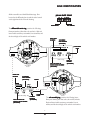
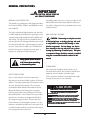
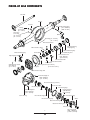
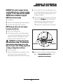
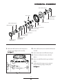
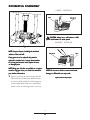
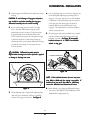
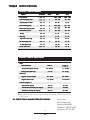
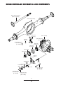
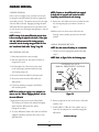
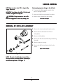
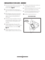
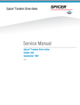
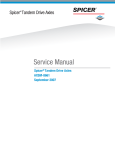
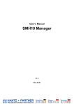
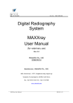
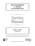
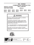
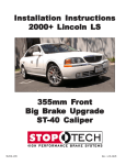
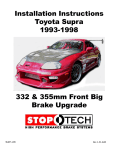
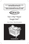
Spicer Drive Axles
®
Service Manual
Spicer® Drive Axles
AXSM-8942
September 2007
TABLE OF CONTENTS
Axle Identification
Model Identification Numbering System
Gear Set Identification
Axle Lubricant Recommendations
General Precautions
Standard Axle Components
Pinion-Up Axle Components
Removal of Differential Carrier from Axle Housing
Removal of Differential from Carrier
Differential Disassembly
Pinion Disassembly
Cleaning and Inspection
Pinion Assembly
Pinion Position
Differential Assembly
Differential Installation
Ring Gear and Pinion Tooth Contact Pattern
Installation of Carrier into Axle Housing
Fastener Torques and Axle Specifications
Driver Controlled Differential Lock
Driver Controlled Differential Lock Components
Towing Procedures/Instructions
Carrier Removal
Removal of Diff-Lock Assembly
Installation of Diff-Lock Assembly
Carrier Installation
Checking Differential Lock Operation
Recommended Service Tools
○
○
○
○
○
○
○
○
○
○
○
○
○
○
○
○
○
○
○
○
○
○
○
○
○
○
○
○
○
○
○
○
○
○
○
○
○
○
○
○
○
○
○
○
○
○
○
○
○
○
○
○
○
○
○
○
○
○
○
○
○
○
○
○
○
○
○
○
○
○
○
○
○
○
○
○
○
○
○
○
○
○
○
○
○
○
○
○
○
○
○
○
○
○
○
○
○
○
○
○
○
○
○
○
○
○
○
○
○
○
○
○
○
○
○
○
○
○
○
○
○
○
○
○
○
○
○
○
○
○
○
○
○
○
○
○
○
○
○
○
○
○
○
○
○
○
○
○
○
○
○
○
○
○
○
○
○
○
○
○
○
○
○
○
○
○
○
○
○
○
○
○
○
○
○
○
○
○
○
○
○
○
○
○
○
○
○
○
○
○
○
○
○
○
○
○
○
○
○
○
○
○
○
○
○
○
○
○
○
○
○
○
○
○
○
○
○
○
○
○
○
○
○
○
○
○
○
○
○
○
○
○
○
○
○
○
○
○
○
○
○
○
○
○
○
○
○
○
○
○
○
○
○
○
○
○
○
○
○
○
○
○
○
○
○
○
○
○
○
○
○
○
○
○
○
○
○
○
○
○
○
○
○
○
○
○
○
○
○
○
○
○
○
○
○
○
○
○
○
○
○
○
○
○
○
○
○
○
○
○
○
○
○
○
○
○
○
○
○
○
○
○
○
○
○
○
○
○
○
○
○
○
○
○
○
○
○
○
○
○
○
○
○
○
○
○
○
○
○
○
○
○
○
○
○
○
○
○
○
○
○
○
○
○
○
○
○
○
○
○
○
○
○
○
○
○
○
○
○
○
○
○
○
○
○
○
○
○
2
3
3
4
5
6
7
8
9
10
12
13
14
17
19
20
21
22
23
24
25
26
27
28
29
30
31
32
GENUINE SPICER SER
VICE P
AR
TS
SERVICE
PAR
ARTS
Should an axle assembly require replacement component parts, it is recommended that Spicer Heavy Axle
Service Parts be used. Spicer Heavy Axle Service Parts
are manufactured under the same rigid specification as
are original equipment axle components. This assures
the customer who uses genuine Spicer service parts,
maximum reliability for a Spicer Heavy Axle assembly.
They may be obtained through your vehicle manufacturer. The use of non-original Spicer service parts may
cause premature component failure and may void the
warranty.
The items included in this book are currently being
offered as service parts at the time of printing. The
part numbers and illustrations are provided specifically
for reference purposes only. Therefore, Spicer reserves
the right to update this manual without notice or
liability.
1
AXLE IDENTIFICA
TION
IDENTIFICATION
All axle assemblies are identified with two tags. One
located on the differential carrier, and the other located
on the right hand side of the axle housing.
JULIAN D
ATE CODE
DA
96 0
70
07
MODEL YEAR
DAY OF YEAR
ential carrier ttag
ag contains the following:
The differ
differential
Dana part number, julian date code, and ratio. Optional
items include customer part number, line set number, and
the last six digits of the vehicle serial number.
DANA P
AR
T
PAR
ART
NUMBER
CUS
TOMER
CUST
PAR
T NUMBER
ART
(OPTIONAL)
JULIAN D
ATE
DA
CODE
Carrier Tag
LAS
T SIX DIGITS OF
LAST
VEHICLE SERIAL NUMBER
(OPTIONAL)
Pinion Below
Center
DANA P
AR
T
PAR
ART
NUMBER
CUS
TOMER
CUST
T NUMBER
PAR
ART
(OPTIONAL)
Axle Assembly Tag
LAS
T SIX DIGITS OF
LAST
VEHICLE SERIAL NUMBER
(OPTIONAL)
LINE SET
NUMBER
(OPTIONAL)
MODEL
JULIAN D
ATE
DA
CODE
Pinion Above
Center
LINE SET
NUMBER
(OPTIONAL)
ssembl
ag contains the following items:
The axle aassembl
ssemblyy ttag
Dana part number, julian date code, axle model, and ratio.
Optional items include customer part number, line set
number, and the last six digits of the vehicle serial number.
2
MODEL IDENTIFICA
TION NUMBERING SYSTEM
IDENTIFICATION
S 230 S L
Family
(S = Spicer)
Nominal Load
Carrying Capacity
(230 = 23,000 Lbs.)
(260 = 26,000 Lbs.)
Gearing Type
(S = Single Reduction)
Options
(N = *No-SPIN® Differential)
(L = Driver Controlled Diff. Lock)
(B = Bus)
* No-SPIN® is a registered trademark of Tractech
GEAR SET IDENTIFICA
TION
IDENTIFICATION
Man
ufactur
er's Da
Manufactur
ufacturer's
Datte- Date gear set was made.
PINION ETCH
SPICER
TRADEMARK
Spicer T
ademark-- Company logo and location of
Trrademark
manufacturing facility.
+15
th Combina
tion(i.e. 4
Too
ooth
Combination(i.e.
41-1
1-11)- Indicates the pinion
has 11 teeth and the ring gear has 41 teeth which
results in a 3:73:1 ratio.
260
41-11
300GP2
03- Part number of pinion gear. (TYPICAL)
00GP20
TOOTH
COMBINATION
Ma
tched Se
Matched
Sett Number
Number-- Spicer ring gears and pinions
are manufactured as matched sets. Both ring gear and
pinion are marked with a corresponding number (i.e.
260), which identifies them as a matched set.
PART
NUMBER
HEAT
CODE
SPICER
TRADEMARK
MFG.
DATE
MATCHED
SET NUMBER
260
L10
A gear set that does not have the same match set
numbers should not be run together. If either ring gear
or pinion require replacement, a new matched set must
be used.
BACKLASH ETCH
Backla
sh Etch- Indicates backlash setting for assembly.
Backlash
Pinion Etch- Indicator for proper pinion position shim
osition Section.
stack up. See Pinion PPosition
3
AXLE
XLE LUBRICANT RECOMENDATIONS
To ensure proper lubrication and operating temperature,
correct lubricants and lubricant levels must be obtained.
APPLICA
TION
APPLICATION
On Highway
PETR
OLEUM B
ASED
PETROLEUM
BASED
MILES
INTER
VAL
INTERV
S
YNTHETIC B
ASED**
SYNTHETIC
BASED**
MILES
INTER
VAL
INTERV
100,000
1 Year
250,000
3 Year
and
50,000
On-Off Highway
1 Year
100,000
1 Year
RECOMMENDED GEAR LUBRICANTS
* Severe Service
Mineral or Synthetic based hypoid gear lubricants that
meet or exceed military specification MIL-L-2105D, and
API service classification GL-5, are the minimum requirements for use in Spicer Medium and Heavy Duty Drive
Axles.
* Severe service includes any applications operating at
or near maximum GVW or GCW ratings. This
includes normally wet or dusty environment, or
consistent high load and low speed applications.
The table below indicates which SAE viscosities are
recommended for various temperature ranges the vehicle
will encounter.
** Includes Semi-Synthetic blends that meet
MIL-L-2105D specifications.
AFTER OVERHAUL OR CHANGE INTERVALS
Fill the axle assembly to the bottom of housing fill hole as
shown in the illustration below. It is recommended that
following an overhaul, each side of the axle be jacked up
seperately to approximately six inches and held into
position for one minute. This procedure will allow
adequate lubricant to flow into the wheel ends and help
eliminate the possibility of premature damage to wheel
bearings and seals. Lower the vehicle to the floor and
allow ten minutes for lube to return to normal level. Check
and refill assembly to bottom of fill hole to replace the
lubricant that was directed into the wheel ends.
SAE 140
SAE 85W-140
SAE 90
SAE 80W-140
SAE 80W
SAE 75W-140
SAE 75W-90
SAE 75W
Cº -40
-26
-12
-40
-15
+10 +32 +40
Fº
0 +4
+15
+27
+38
Cº
+60
+80
+100
Fº
AMBIENT AIR TEMPERATURE
SERVICE
Recommended lubricant change intervals are dependent
on the application and operating environment. The
following chart should be used to establish proper
change intervals.
SUBMERSION OR DEEP WATER FORDING
NO
TE: Lubricant close enough to the bottom of the fill hole to be seen or
NOTE:
touched is not sufficient. Lubricant must be level with the fill hole.
In the event the carrier housing should become
submerged in water, particularly if over the vent or
breather, it is recommended that the lubricant be
drained and all internal parts be inspected for water
damage and/or contamination. Reassemble the carrier to
the housing and refill with specified gear lubricant.
4
GENERAL PRECAUTIONS
IMPOR
TANT
IMPORT
READ THIS SECTION BEFORE ST
AR
TING
STAR
ARTING
ANY SER
VICE PROCEDURES
SERVICE
GENERAL AXLE DESCRIPTION
Accordingly, anyone who uses a service procedure or tool
different than shown must insure that their safety, and
the vehicle's safety, will not be jeopardized by the service
method selected.
This manual covers maintenance and rebuild procedures
for the Spicer S230-S, S230-SL, and S260-SB rear drive
axle assemblies.
The Spicer Heavy Duty Single Reduction rear drive axle
is a full floating axle assembly, with a hypoid gear carrier
assembly, using a High Strength Low Alloy (HSLA) steel
axle housing. The hypoid pinion is straddle mounted
with two tapered roller bearings behind the pinion teeth
for thrust and radial loads. A pilot bearing is located on
the nose of the pinion for radial load. The differential
itself uses four precision forged pinion mate gears, a
forged cross, and precision forged side gears.
END YOKES AND FLANGES
CA
UTION: Hammering on end yyok
ok
CAUTION:
okees can close
in the bearing bor
ok
borees or misalign yyok
okee lugs and rreesult
in earl
ther
earlyy failur
failurees of journal needle bearings or oother
eline component
s. Serious damage can also be
driv
driveline
components.
done int
ernall
o the ring and pinion se
internall
ernallyy tto
sett or pinion
ok
xt
ernal par
bearings bbyy hammering on eext
okees
xternal
partts. End yyok
or companion flange
emo
alled
flangess should be rremo
emovved or inst
installed
using the rrecommended
ecommended me
thods outlined in this
methods
man
ual.
manual.
Safety glasses should be wor
n
worn
at all times when assembling
or disassembling axles.
CLEANLINESS
Axle components should be steam cleaned prior to
removal from the vehicle. Dirt is abrasive and will cause
premature wear of otherwise serviceable parts.
Service personnel should use a wash tank for thorough
cleaning of parts just prior to reassembly.
SAFTEY PRECAUTIONS
Proper service and repair of vehicle components is
important to the safe and reliable operation of all motor
vehicles. This applies particularly to driving axles such as
the ones described in this manual. The procedures
recommended and described in this manual are tested,
effective methods for performing service operations.
Follow each procedure closely, making use of both the
text and illustrations. Some of these service procedures
show the use of certain tools designed specifically for
the operation being performed. They are shown as a
preferred means of performing the operation. It is not
practical to anticipate and advise the service trade of all
possible alternative methods, and of all possible hazardous consequences that could occur.
CAUTION
BR
AKE LININGS CONT
AIN NON-ASBES
TOS FIBER
S
BRAKE
CONTAIN
NON-ASBEST
FIBERS
BREA
THING BR
AKE DUS
T MA
Y BE HAZARDOUS T
OY
OUR HEAL
TH AND
BREATHING
BRAKE
DUST
MAY
TO
YOUR
HEALTH
MA
Y CA
USE SERIOUS RESPIR
ATOR
Y OR O
THER BODIL
Y HARM.
MAY
CAUSE
RESPIRA
ORY
OTHER
BODILY
AVOID CREA
TING DUS
T
CREATING
DUST
VE BR
AKE DR
UM WITHOUT PR
OPER PR
OTECTIVE EQ
UIPMENT
NOT
REMOVE
BRAKE
DRUM
PROPER
PRO
EQUIPMENT
UIPMENT..
DO NO
T REMO
OPER PR
OTECTIVE EQ
UIPMENT
NOT
WORK
PROPER
PRO
EQUIPMENT
UIPMENT..
DO NO
T W
ORK ON LININGS WITHOUT PR
OPER PR
OTECTIVE EQ
UIPMENT
NOT
REPLACE
PROPER
PRO
EQUIPMENT
UIPMENT..
DO NO
T REPLA
CE LININGS WITHOUT PR
TER BR
AKE
NOT
ATTEMPT
TO
SAND,
ALTER
BRAKE
DO NO
TA
TTEMPT T
OS
AND, GRIND, CHISEL, FILE, HAMMER OR AL
PROPER
PRO
EQUIPMENT
UIPMENT..
LININGS IN ANY MANNER WITHOUT PR
OPER PR
OTECTIVE EQ
UIPMENT
FOLL
OW 0.S.H.A. S
TAND
ARDS FFOR
OPER PR
OTECTIVE DEVICES T
O BE USED
OLLO
ST
ANDARDS
PROPER
PRO
TO
OR PR
ORKING WITH BR
AKE MA
TERIALS.
WORKING
BRAKE
MATERIALS.
WHEN W
5
ST
ANDARD AXLE COMPONENTS
STANDARD
Axle Shaft
Housing
Breather
Differential Bearing Cap Bolt
(295 - 340 Lb-Ft)
(400 - 461 N-m)
Fill Plug
(35-45 Lb-Ft)
(47 - 61 N-m)
Temperature
Sensor Plug
(35 - 45 Lb-Ft)
(47 - 61 N-m)
Washer
Drain Plug (35 - 45 Lb-Ft)
(47 - 61 N-m)
Differential Bearing
Adjusting Ring
Differential Bearing Cup
Differential Case Half
Differential Bearing Cap
Differential Bearing Cone
Differential Case Flange Half
Adjusting Ring Lock
Ring Gear
Ring Gear Rivet (45-50 tons)
(41-45 metric tonnes)
Thrust Washer
Differential Pinion Mate
Differential Cross Shaft
Differential Side Gear
Thrust Washer
Differential Case Bolt
(160 - 180 Lb-Ft)
(217- 244 N-m)
Adjusting Ring Lock Bolt
(20 - 30 Lb-Ft)
(27 - 41 N-m)
Ring Gear Bolt Kit - Service
No-Spin® Differential
Carrier Mounting Bolt
(240 - 260 Lb-Ft)
(325 - 353 N-m)
Inner Pinion Bearing Cone
Inner Pinion Bearing Cup
Pinion Preload Spacer (Selective)
Pinion Position Shim
Pinion Bearing Cage
Outer Pinion Bearing Cup
Carrier Housing
Pilot Bearing
Bearing Cage Bolt
(160-180 Lb-Ft)
(217- 244 N-m)
Outer Pinion Bearing Cone
Pinion
Pinion Seal
End Yoke Assembly
Pinion Hex Nut
(900 - 1,200 Lb-Ft)
(1,220 - 1,627 N-m)
6
Washer
PINION-UP AXLE COMPONENTS
Axle Shaft
Housing
Breather
Differential Bearing Cap Bolt
(295 - 340 Lb-Ft)
(400 - 461 N-m)
Fill Plug
(35-45 Lb-Ft)
(47 - 61 N-m)
Temperature
Sensor Plug
(35 - 45 Lb-Ft)
(47 - 61 N-m)
Washer
Drain Plug (35 - 45 Lb-Ft)
(47 - 61 N-m)
Differential Side Gear
Differential Bearing
Adjusting Ring
Differential Cross Shaft
Differential Bearing Cup
Differential Bearing Cap
Thrust Washer
Adjusting Ring Lock
Adjusting Ring Lock Bolt
(20 - 30 Lb-Ft)
(27 - 41 N-m)
Ring Gear
Differential Bearing Cone
Differential Case Bolt
(160 - 180 Lb-Ft)
(217- 244 N-m)
Differential Case Half
Differential Pinion Mate
Thrust Washer
Ring Gear Rivet (45-50 tons)
(41-45 metric tonnes)
Differential Case Flange Half
Carrier Mounting Bolt
(240 - 260 Lb-Ft)
(325 - 353 N-m)
Pinion Preload Spacer (Selective)
Pinion Position Shim
Pinion Bearing Cage
Bearing Cage Bolt
(160-180 Lb-Ft)
(217- 244 N-m)
Pilot Bearing
Carrier Mounting Bolt
(240 - 260 Lb-Ft)
(325 - 353 N-m)
Carrier Housing
Pinion
End Yoke Assembly
Inner Pinion Bearing Cone
Inner Pinion Bearing Cup
Washer
Outer Pinion Bearing Cup
Outer Pinion Bearing Cone
Pinion Seal
7
Pinion Hex Nut
(900 - 1,200 Lb-Ft)
(1,220 - 1,627 N-m)
REMOV
AL OF DIFFERENTIAL
REMOVAL
CARRIER FROM AXLE HOUSING
IMPOR
TANT
ehicle is equipped with driv
er
IMPORT
ANT:: If the vvehicle
driver
contr
olled differ
ential lock, see instructions begining
controlled
differential
on page 2
4. T
o tto
ow a vvehicle
ehicle with driv
er contr
olled
24.
To
driver
controlled
6.
differ
ential lock, see instructions on page 2
differential
26.
8. Use a breaker bar to loosen the differential carrierto-housing mounting bolts. Remove all bolts except
top two. These two bolts will prevent the carrier
assembly from falling.
NO
TE: St
eam clean axle aassembl
ssembl
NOTE:
Steam
ssemblyy.
9. Separate differential carrier from the housing using
igur
removal slots. See FFigur
iguree 1. Be certain carrier is
balanced properly on jack, and remove top two
carrier-to-housing mounting bolts. Remove
differential carrier assembly from the axle housing.
1. Block wheels.
2. Remove axle housing drain plug and drain lubricant.
3. Disconnect drive shafts at the rear U-joint.
NO
TE: If end yyok
ok
o be rreplaced,
eplaced,
NOTE:
okee and/or seal is tto
loosen yyok
ok
ut aatt this time.
okee nnut
4. Remove axle shaft flange nuts.
5. Hold a large brass drift or a brass hammer against
the center of the axle shaft flange. Strike the drift
with sharp blows from a large hammer or sledge
until the axle shaft separates from the hub.
CA
UTION: Do no
ectl
CAUTION:
nott strik
strikee the flange dir
directl
ectlyy
with a st
eel hammer or sledge. This ma
ack and
steel
mayy cr
crack
splint
er ma
splinter
matterial, possibl
possiblyy causing serious or fa
fattal
injury
way fr
om hhub
ub
injury.. Do no
nott pry or chisel axle flange aaw
from
or damage tto
o sealing sur
face
surface
facess could occur
occur..
Remo
emovval slot
Remo
emovval slot
Figur
iguree 1
6. Remove axle shafts.
10. Mount carrier assembly in a suitable rebuild stand.
ools
(Refer to Recommended Service T
Tools
ools, pg. 32).
7. Support the differential carrier assembly on a roller
jack. Secure as necessary to prevent it from
falling off the jack when removed from the housing.
Differ
ential Carrier RRemo
emo
Differential
emovval Complet
Completee
8
REMOV
AL OF DIFFERENTIAL FROM CARRIER
REMOVAL
1. Remove adjusting ring locks from bearing caps.
3. Loosen four bearing cap retainer bolts.
2. Match mark one differential bearing cap and leg with
center punch or chisel for correct reassembly. See
Figur
iguree 2.
4. Loosen adjusting rings, relieving bearing preload.
5 . Remove four bearing cap retainer bolts.
6. Remove bearing caps.
7. Remove adjusting rings.
8. Carefully lift the ring gear and differential
subassembly out of the carrier.
NO
TE: Use car
o damage the ring gear and
NOTE:
caree no
nott tto
pinion. If either ring gear or pinion sho
w signs of
show
damage, the
ust be rreplaced
eplaced aass a ma
tched se
t.
theyy m
must
matched
set.
RRemo
emo
ential Complet
emovval of Differ
Differential
Completee
Figur
iguree 2
9
DIFFERENTIAL DISASSEMBL
Y
DISASSEMBLY
Differential Bearing Cone
Thrust Washer
Differential Bearing
Adjusting Ring
Differential Bearing Cup
Differential Case Half
Differential Bearing Cone
Ring Gear
Differential Bearing Cup
Ring Gear Rivet (45-50 tons)
Differential Pinion Mate
Differential Cross Shaft
Differential Side Gear
Thrust Washer
Differential Case Half
Differential Bearing
Adjusting Ring
Differential Case Bolt
(160-180 Lb-Ft)
(217- 244 N-m)
1. Match mark differential case halfs with punch or
chisel for correct alignment in reassembly.
See FFigur
igur
iguree 3.
2. Remove differential case bolts and lift off differential
case half.
3. Remove thrust washer and differential side gear.
4. Lift out cross shaft, pinion mates, and thrust
washers.
5. Remove second differential side gear and thrust
washer.
6. If differential side bearings are to be replaced,
remove old bearings using a suitable puller.
See FFigur
igur
iguree 4.
Figur
iguree 3
10
DIFFERENTIAL DISASSEMBL
Y
DISASSEMBLY
CORRECT PROCEDURE
Ca
se
Case
Ring Gear
CA
UTION: Alw
CAUTION:
Alwaays use a soft hammer or H.D.
pla
stic head hammer tto
o strik
plastic
strikee punch.
INCORRECT PROCEDURE
Figur
iguree 4
NO
TE: Inspect all par
NOTE:
partts, including the machined
se half
sur
face
surface
facess of the ca
case
half..
Ring Gear
Ca
se
Case
If an
o be rreplaced,
eplaced, the
ust be
anyy gear
gearss ar
aree tto
theyy m
must
tched se
replaced in ma
sherss
matched
setts. Inspect thrust w
waasher
ear
eplace all w
orn
for scoring and eexxce
ssiv
ssivee w
wear
ear.. RReplace
worn
cessiv
or damaged par
partts.
NO
TE: Ring gear bolt kit
eplaceNOTE:
kitss ar
aree aavvailable aass a rreplacement for ring gear riv
ar
ual for
riveets, see PPar
artts List man
manual
par
umber informa
tion.
partt nnumber
information.
NO
TE: Do no
o rremo
emo
NOTE:
nott use a chisel tto
emovve riv
riveet heads,
se ma
damage tto
o differ
ential ca
differential
case
mayy rreesult.
7. When it is necessary to remove ring gear from the
differential case, carefully center punch each rivet
head. Use a 9/16 inch drill bit. Drill through rivet
heads to depth shown. Next, use a rounded type
punch to drive out remaining portion of the rivet.
Differ
ential Disa
ssembly Complet
Differential
Disassembly
Completee
11
PINION DISASSEMBL
Y
DISASSEMBLY
Pinion Bearing Cage
Outer Pinion Bearing Cup
Carrier Housing
Bearing Cage Bolt
(160-180 Lb-Ft)
(217-244 N-m)
Pilot Bearing
Pinion
Outer Pinion Bearing Cone
Inner Pinion Bearing Cone
Pinion Seal
End Yoke Assembly
Washer
Inner Pinion Bearing Cup
Pinion Preload Spacer (Selective)
Pinion Position Shim(s)
Pinion Hex Nut
(900 - 1,200 Lb-Ft)
(1,220 - 1,627 N-m)
6. Located between the pinion bearings is a selective
bearing preload spacer. Retain this selective preload
spacer for possible use during reassembly.
1. Remove pinion bearing cage mounting bolts.
2. Remove pinion assembly from carrier housing.
If difficulty is encountered in removing pinion
assembly from carrier housing, place a brass drift on
inner end of pinion and tap lightly with hammer.
7. Remove the old pinion seal and discard. Always use
a new seal at the time of reassembly.
8. Lift out the outer pinion bearing cone.
NOTE:
NO
TE: RReetain shims for possible use during
rea
ssembl
eassembl
ssemblyy.
9. Remove inner pinion bearing cup, using a suitable
adapter and press or puller.
3. Hold yoke stationary. Remove nut and washer. A
torque multiplier may be required to loosen nut.
CA
UTION: Do no
e.
CAUTION:
nott nick bearing bor
bore.
4. Remove the end yoke using a suitable puller. See
Recommended Service T
ools
Tools
ools, pg. 32.
10. Remove the outer pinion bearing cup, use the same
procedure as in step 9.
5. Remove pinion from cage assembly.
11. Remove pilot bearing from end of pinion.
ssary tto
o ttap
ap out
er end of
NO
TE: It ma
outer
NOTE:
mayy be nece
necessary
pinion with a soft hammer
aking car
o damage
hammer,, ttaking
caree no
nott tto
thr
eads.
threads.
12. Remove inner bearing cone from pinion.
Pinion Disa
ssembly Complet
Disassembly
Completee
12
CLEANING AND INSPECTION
CLEANING
GEARS
1. Parts should be cleaned with emulsion cleaners or
petroleum base cleaning solvent.
NO
TE: Alk
aline ttype
ype solutions ma
o
NOTE:
Alkaline
mayy cause damage tto
machined sur
face
surface
facess and should be aavvoided.
2. Make sure interior of axle housing is clean prior to
reassembly.
3. Clean all gasket surfaces of old material.
DRYING
Use soft, clean, lintless towels or rags to dry components after cleaning. Bearings should NOT be dried by
spinning with compressed air. This can damage mating
surfaces due to the lack of lubrication.
Inspect gears for excessive wear or damage. Replace
gears that are pitted, scored, broken, or worn.
SHAFTS
After drying, parts should be coated with a light coat
of lubricant or rust inhibitor to prevent damage from
corrosion. If parts are to be stored for a prolonged
period, they should be wrapped in wax paper.
INSPECTION
Inspect shafts for nicks or scoring.
Prior to reassembly, inspect parts for signs of excessive
wear or damage. Replacement of these parts can
prevent premature failure and costly downtime.
SPLINES
BEARINGS
Inspect all splines for excessive wear, distortion from
twisting, and cracking.
HOUSINGS
Bearing surfaces should be inspected for pitting,
excessive wear, or overheating.
THRUST WASHERS
Inspect housing for stripped threads and bending
fatigue.
Inspect thrust washers for scoring and cracking.
13
PINION ASSEMBL
Y
ASSEMBLY
Pinion Bearing Cage
Outer Pinion Bearing Cup
Carrier Housing
Bearing Cage Bolt
(160-180 Lb-Ft)
(217- 244 N-m)
Pilot Bearing
Pinion
Outer Pinion Bearing Cone
Inner Pinion Bearing Cone
Pinion Seal
End Yoke Assembly
Washer
Inner Pinion Bearing Cup
Pinion Preload Spacer (Selective)
Pinion Hex Nut
(900 - 1,200 Lb-Ft)
(1,220 - 1,627 N-m)
Pinion Position Shim(s)
1. Press inner pinion bearing cone onto pinion.
2. Press Pilot bearing onto the pinion.
5. Install outer pinion bearing cup into pinion bearing
cage.
3. Stake Pilot bearing in nine places (See illustration
below), using a center punch or equivalent tool.
This operation will move gear shaft material outward
into bearing chamfer.
6. Use a feeler gauge or shim stock (.002 in. Max.) to
ensure bearing cups are completely seated in
bearing bores. This is necessary for the proper
igur
pinion position. See FFigur
iguree 5.
Figur
iguree 5
4. Install inner pinion bearing cup into pinion bearing
cage.
7. Place the selective preload spacer, that was removed
during disassembly, onto pinion.
14
PINION ASSEMBL
Y
ASSEMBLY
Me
thod A uses a pull scale and a strong cord approxiMethod
thod B uses a Lb-in
mately 8 ft. long. (See Item 11). Me
Method
torque wrench. Both methods measure torque to rotate.
(See Item 12).
8. Place pinion bearing cage onto inner pinion
bearing.
9. Install the outer pinion bearing cone onto pinion.
10. Without installing seal, install end yoke onto pinion
igur
using yoke installer service tool. See FFigur
iguree 6. This
will allow proper setting of pinion preload. Secure
yoke with a Yoke and Flange Holding Bar or an
equivalent tool. Install pinion nut and washer.
Torque pinion nut to 900-1,200 Lb-Ft (1,2201,627 N-m).
11. Me
thod A: To measure torque-to-rotate with the
Method
spring scale, clamp the end yoke horizontally in a
soft-jawed vise. Attach one end of the cord to a bolt
hole in the pinion cage, wrap cord around pinion
cage and attach the outer end of the cord to the
spring scale. Rotate pinion cage by pulling scale.
Read scale during fourth revolution. Scale reading
must be between 3-10 Lbs (1.4-4.5 Kg) See
Figur
iguree 7.
NO
TE: Inspect end yyok
ok
face for gr
oo
NOTE:
okee seal sur
surface
groo
oovves
caused bbyy lip of seal. If gr
oo
ed with
groo
oovves can be de
dettect
ected
fingernail, it should be rreplaced.
eplaced.
Figur
iguree 7
Figur
iguree 6
(Continued on Ne
xt PPage)
age)
Next
CA
UTION: The pinion cage should be rro
otated
CAUTION:
periodicall
ening the pinion nnut
ut tto
o sea
periodicallyy while tight
tightening
seatt
and align the pinion bearings.
There are two methods of measuring pinion bearing
preload and both are acceptable. Mechanic's preference
and available tools should determine which method
is used.
15
PINION ASSEMBL
Y
ASSEMBLY
Inche
Inchess
.896
.897
.898
.899
.900
.901
.902
.903
.904
.905
.906
.907
.908
.909
.910
.911
.916
12. Me
thod B: To measure torque to rotate with the
Method
torque wrench, assemble pinion cage into the carrier
housing and install two mounting bolts to anchor
the unit.
Rotate pinion with the torque wrench. See FFigur
iguree 8
8.
igur
Torque measurement will be taken during fourth revolution and must be between 10-40 Lb-in (1.1-4.5 N-m)
without pinion seal.
NO
TE: Closer adjustment can be made bbyy sanding
NOTE:
ne
xt thick
er spacer tto
o de
sir
ed thickne
ss using emery
next
thicker
desir
sired
thickness
clo
th on a fla
face. Sur
face
ust be par
allel tto
o
cloth
flatt sur
surface.
Surface
facess m
must
parallel
each oother
ther and squar
o bor
squaree tto
boree diame
diametter
er..
Figur
iguree 8
CA
UTION: W
oughl
CAUTION:
Waash spacer thor
thoroughl
oughlyy of emery
NO
TE: When ttor
or
que tto
o rro
otate rreading
eading doe
NOTE:
orque
doess no
nott fall
within allo
wable limit
s, bearing pr
eload can be
allow
limits,
preload
incr
ea
sed bbyy using a thinner spacer or decr
ea
sed bbyy
increa
eased
decrea
eased
1 in. (.0
25 mm) change in
using a thick
er spacer
.001
(.02
thicker
spacer.. .00
eading bbyy
pr
eload spacer thickne
ss, change
preload
thickness,
changess scale rreading
appr
oxima
0 lbs, .00
1 in. change in pr
eload
ximattel
elyy 1
10
.001
preload
appro
spacer will change ttor
or
que tto
o rro
otate bbyy appr
oxima
orque
appro
ximattel
elyy
30 Lb- in. This is onl
onlyy a guide, individual carrier
carrierss ma
mayy
vary slightl
slightlyy.
alling on pinion.
cuttings
beforee inst
installing
cut
tings befor
14. After proper torque to rotate is achieved remove
end yoke.
15. Clean and dry threads on pinion.
16. Install pinion oil seal with Recommended Service
Tool
ool. See page 32.
The pinion bearing spacers are available in the following
thicknesses. Measure spacer with micrometers before
assembly to ensure correct thickness.
Inche
Inchess
.893
.894
.895
MM
22.758
22.784
22.809
22.835
22.860
22.885
22.911
22.936
22.962
22.987
23.012
23.038
23.063
23.089
23.114
23.139
23.266
17. Install end yoke using yoke installer service tool
igur
DST1007. See FFigur
iguree 6.
18. Coat threads with Loctite #680 adhesive
compound.
MM
22.982
22.708
22.733
(Continued on Ne
xt PPage)
age)
Next
16
PINION POSITION
19. Install pinion nut and washer. Use torque multiplier
and torque pinion nut to 900-1,200 Lb-Ft (1,2201,627 N-m).
If a new gear set is being used, notice the (+), (–) or "0"
etching on both the old and the new pinions, and adjust
the thickness of the shims to compensate for the
difference of these two figures (as shown in table on next
page).
Pinion assembly is now ready to be installed into carrier
housing.
For example, if the old pinion is etched +2, and the new
pinion is –2, subtract .004 in. from the thickness of the
original shims used to position the pinion.
Pinion Assembly Complet
Completee
Ring gears and pinions are supplied in matched sets
only. Matching numbers on both the pinion and ring
gear are etched for verification. If a new gear set is
being used, verify the numbers of each pinion and ring
gear before proceeding with assembly.
If either or both the pinion gears are etched beyond the
values on this chart, follow the same procedure to
establish correct pinion position.
For example if the old pinion is etched –12 and the new
pinion is etched +9, add .021 inch to the thickness of the
original shims.
When a new gear set is being installed, use a micrometer
to measure the thickness of the old pinion position shims.
Measure each shim separately and add together to get
the total thickness of the original build-up.
After determining the new total build up of pinion position
shims, round the figure off to the nearest multiple of .005
inch.
NO
TE: If old shims ar
utila
NOTE:
aree bent or m
mutila
utilatted the
theyy should
be rreplaced.
eplaced.
Use the Pinion Setting Chart on the next page as a
guideline to set the pinion.
17
PINION SETTING CHAR
T
CHART
18
DIFFERENTIAL ASSEMBL
Y
ASSEMBLY
Differential Bearing Cone
Thrust Washer
Differential Bearing
Adjusting Ring
Differential Bearing Cup
Differential Case Flange Half
Differential Bearing Cone
Ring Gear
Differential Bearing Cup
Ring Gear Rivet (45-50 tons)
(41-45 metric tonnes)
Differential Pinion Mate
Differential Cross Shaft
Differential Side Gear
Thrust Washer
Differential Case Half
Differential Bearing
Adjusting Ring
Differential Case Bolt
(160 - 180 Lb-Ft)
(217 - 244 N-m)
Corr
ect riv
et head shape
Correct
rivet
operly compr
properly
compreessed
when pr
3. Apply a small amount of gear lubricant to all mating
surfaces. This will aid in assembly by keeping parts
together and providing initial lubrication.
4. Place thrust washer and side gear in differential case
flange half.
5. Assemble pinion mates and thrust washers onto
differential cross shaft. Place assembly into flange
half differential case.
1. If ring gear was removed from the differential case,
reinstall it at this time. Bolt ring gear to differential
case in three places, 120° apart, before compressing
rivet; this will eliminate ring gear runout. Use a
hydraulic or mechanical press and riveting fixture.
Pressure requirement per rivet is 45-50 U.S. tons or
(41-45 metric tonnes).
6. Place remaining side gear and thrust washer in
position on differential pinion mates.
7. Assemble case halves, making sure match marks are
lined up.
8. If reinstalling used bolts, clean threads and apply
Loctite #277. Install differential case bolts and
torque evenly to 160-180 Lb-Ft (217- 244 N-m).
2. Press bearing cones onto differential case halves.
Place bearing cups on cones during remainder of
assembly to prevent damage of bearings.
Differ
ential Assembly Complet
Differential
Completee
NO
TE: Ring gear bolt kit
eplaceNOTE:
kitss ar
aree aavvailable aass a rreplaceual for par
ment for ring gear riv
riveets, see par
partts list man
manual
partt
number informa
tion.
information.
19
DIFFERENTIAL INST
ALLA
TION
INSTALLA
ALLATION
1. Install ring gear and differential assembly into carrier
housing.
4. Loosen adjusting ring on tooth side of ring gear one
notch and tighten adjusting ring on flange side of
ring gear one notch. Repeat process until backlash
is eliminated. Tighten adjusting ring on tooth side
of the ring gear until the ring gear and pinion
backlash matches the backlash etched on the
ring gear. This adjustment sets both the backlash
and the bearing preload.
CA
UTION: T
o aavvoid damage of ring gear and pinion,
CAUTION:
To
car
alling the ring gear
caree should be used when inst
installing
differ
ential aassembl
ssembl
o the carrier housing.
differential
ssemblyy int
into
2. Be sure side bearing cups are seated on bearing
cones. Assemble differential bearing caps, with
match marks in proper location. Clean bearing cap
bolts and washers and coat threads with Loctite
#277. Install bearing cap bolts and tighten enough
to draw bolt head into contact with bearing cap,
eliminating visible space between differential bearing
cap and carrier housing. Do not torque the cap
bolts at this time.
5. Check ring gear and pinion backlash in four equally
spaced positions around the ring gear with a dial
igur
0. A
ccep
indicator as shown. See FFigur
iguree 1
10.
Accep
ccepttable
backla
sh ttoler
oler
ance is +/- .00
2" fr
om backla
sh
backlash
olerance
.002"
from
backlash
etched on ring gear
gear..
CA
UTION: Differ
ential aassembl
ssembl
ust be
CAUTION:
Differential
ssemblyy m
must
eload is applied
aligned within bearing bor
borees befor
beforee pr
preload
or damage tto
o bearings can occur
occur..
Figur
0
iguree 1
10
NO
TE: If the backla
sh ttoler
oler
ance doe
ary mor
NOTE:
backlash
olerance
doess no
nott vvary
moree
80 mm), the se
than .00
4 in. (.0
accepttable. If
.004
(.08
settting is accep
backla
sh doe
ary mor
4 in. (.0
80 mm),
.004
(.08
backlash
doess vvary
moree than .00
ential and de
remo
emovve the differ
differential
dettermine the cause.
Figur
iguree 9
6. Once backlash is set, torque the differential bearing
cap bolts to 295-340 Lb-Ft (397-460 N-m). Check
backlash after torquing cap bolts.
3. Install adjusting rings. Tighten both adjusting rings
until end play is eliminated, and there is backlash
igur
iguree 9.
between the ring gear and pinion. See FFigur
20
RING GEAR AND PINION
TOOTH CONT
ACT P
ATTERN
CONTACT
PA
PR
OFILE
PROFILE
The following procedures are to be used to establish
proper gear tooth pattern after assembly of the carrier is
complete.
eused, mea
NO
TE: If ma
tched se
aree being rreused,
measur
suree
NOTE:
matched
setts ar
sur
ea
sand rrecor
ecor
d backla
sh befor
ssembl
easecord
backlash
beforee disa
disassembl
ssemblyy, and rrea
semble tto
o the same backla
sh. This will ma
tch ring
backlash.
match
and pinion gear
o the eest
st
ablished w
ear pa
gearss tto
stablished
wear
pattterns.
Hand rrolled
olled pa
ss ar
ea than the
pattterns will co
covver le
less
area
gear pa
st
ablished bbyy pr
patttern eest
stablished
preevious service.
TOP LAND
TOE
CO
AS
T SIDE
COAS
AST
LENGTHWISE
ARC
BEARING AR
C
HEEL
DRIVE SIDE
ROO
T
OOT
STEP 1. Paint 1/4 ring gear with marking compound on
both the drive and coast side.
STEP 2. Apply drag load to ring gear and rotate pinion
so that ring gear completes one revolution in
each direction.
CORRECT GEAR P
ATTERNS
PA
LIGHTL
Y LLO
OADED
LIGHTLY
HEA
VIL
Y LLO
OADED
HEAVIL
VILY
TOE
TOE
HEEL
HEEL
HEEL
DRIVE SIDE
(CONVEX)
COAST SIDE
(CONCAVE)
HEEL
DRIVE SIDE
(CONVEX)
COAST SIDE
(CONCAVE)
INCORRECT GEAR P
ATTERNS
PA
HEA
VIL
Y LLO
OADED
HEAVIL
VILY
LIGHTL
Y LLO
OADED
LIGHTLY
TOE
TOE
HEEL
DRIVE SIDE
(CONVEX)
HEEL
HEEL
COAST SIDE
(CONCAVE)
DRIVE SIDE
(CONVEX)
21
HEEL
COAST SIDE
(CONCAVE)
INST
ALLA
TION OF DIFFERENTIAL
INSTALLA
ALLATION
CARRIER INTO AXLE HOUSING
7. Install the new axle flange gasket.
1. Thoroughly clean the inside of the carrier housing
and inspect the housing mounting surface for nicks
and general cleanliness. Stone the surface if
necessary to remove burrs or nicks. Bolt holes must
also be checked, to see that they are free of
contaminants.
8. Install the axle shafts to proper location.
Torque the axle flange nuts to vehicle manufacturers
specifications.
9. Clean drain plug and install. Torque drain plug to
35-45 Lb-Ft (47-61 N-m) Fill unit to proper
level with hypoid gear lubricant.
10. Install fill plug and torque to 35-45 Lb-Ft
(47-61 N-m).
Loctit
18
Loctitee 5
51
Ga
sk
et Eliminat
or
Gask
sket
Eliminator
Figur
iguree 11
2. Apply an .125 inch (3.175 mm) diameter bead of
Loctite 518 gasket eliminator onto the axle housing
mounting flange and around each bolt hole. See
Figur
iguree 11.
NOTE : Lubricant close enough to bottom of fill hole to be seen
or touched is not sufficient. Lubricant must be level with the fill
hole.
3. Thread two studs into the axle housing 1800 apart.
This will eliminate rotation of the carrier assembly
after it makes contact with the gasket material..
CAP
ACITIES (Appr
oxima
CAPA
(Appro
ximatte*):
4. Install the carrier assembly into the axle housing.
If reinstalling used bolts, clean the mounting bolts,
and coat with Loctite #277, and install. Tighten
bolts evenly in cross pattern. Torque bolts
240-260 Lb-Ft (325-352 N-m).
Model
Pint
Pintss
Lit
er
Liter
erss
S 230-S/SL
S2
60-SB **
S26
S2
60-SB ***
S26
48.8
52.9
55.2
23.1
25.0
26.1
5. Allow one hour cure time for gasket material before
adding hypoid gear lubricant.
* Lube capacity will vary depending upon the housing angle
in each vehicle. Capacities given above are for an angle of
4°. Fill to the lower edge of the fill hole in the axle housing
as shown above.
** Capacity for fabricated housing
6. Remove the old axle flange gasket and clean mating
surfaces of the hub and axle flange.
*** Capacity for cast housing
22
TORQUE SPECIFICA
TIONS
SPECIFICATIONS
S230-S/SL, S260-SB Fasteners
Thr
ead size
Thread
Position
Pinion He
Hexx Nut
Gr
ade
Grade
1 3/4 – 1
2
12
Lb-Ft
N-m
9
00 - 1,2
00
900
1,200
1,2
20 - 1,6
27
1,22
1,62
Pinion Bearing Cage Bolt
Boltss
9/16 – 12
8
1
60 - 180
16
217 - 2
44
24
A
djusting Ring Lock Bolt
Adjusting
Boltss
3/8 – 1
6
16
8
2
0-3
0
20
30
2
7-4
1
27
41
Carrier Mounting Bolt
Boltss
5/8 – 11
8
2
40 - 2
60
24
26
3
25 - 3
52
32
35
Differ
ential Bearing Cap Bolt
Differential
Boltss
3/4 – 1
0
10
8
2
95 - 3
40
29
34
397 - 4
60
46
9/16 – 12
8
1
60 - 1
80
16
18
217 - 2
44
24
Differ
ential Ca
se Bolt
Differential
Case
Boltss
FFill
ill Plug
3/4 – 1
4
14
3
5-4
5
35
45
4
7-6
1
47
61
Dr
ain Plug
Drain
3/4 – 1
4
14
3
5-4
5
35
45
4
7-6
1
47
61
T
emper
Temper
emperaatur
turee Sensor Plug
3/4 – 1
4
14
3
5-4
5
35
45
4
7-6
1
47
61
Air Shift Cylinder Bolt
3/8 – 16
3
0-4
0
30
40
4
1-5
4
41
54
Air Shift Cylinder Plug
1/4 – 18
2
0-3
0
20
30
2
7-4
1
27
41
9/16 – 1
8
18
2
0-3
0
20
30
2
7-4
1
27
41
Electric Switch Unit
8
NO
TE: Refer to vehicle manufacturer specifications for axle Flange-Wheel Nut fastener torque.
NOTE:
S230-S/SL, S260-SB Specifications
Position
U.S.
Me
tric
Metric
Pinion
Nominal Dimension
4.5
945 in.
4.59
10 - 4
0 Lb-in
40
Bearing Pr
eload (T
or
que W
Preload
(Tor
orque
Wrrench)*
Bearing Pr
eload (Pull Scale)*
Preload
116.7
00 mm
6.700
1.1 - 4.5 N-m
3 - 9 Lbs.
1.4 - 4.5 Kg.
.0
12 - .0
16 in.
.01
.01
.3
0 - .4
0 mm
.30
.40
Differ
ential
Differential
Ring Gear tto
o Pinion Backla
sh
Backlash
Ring Gear Riv
Riveet Pr
Preessur
ssuree
45 - 5
0 ttons
ons
50
41 - 4
5 ttonne
onne
45
onness
Lubrica
tion (Appr
ox.**)
Lubrication
(Appro
S2
30-S/SL Lube capacit
S23
capacityy
48.8 Pt
s.
Pts.
23.1 Lit
er
Liter
erss
S2
60-SB FFabrica
abrica
S26
abricatted Housing Lube Capacit
Capacityy
52.9 Pt
s.
Pts.
25.0 Lit
er
Liter
erss
S2
60-SB Ca
st Housing Lube Capacit
S26
Cast
Capacityy
55.2 Pt
s.
Pts.
26.1 Lit
er
Liter
erss
* Pinion bearing preload is established prior to installation of pinion seal.
** Capacity will vary depending on the housing angle in each vehicle. Fill to lower edge of fill hole in rear of axle housing
as shown on Page 22.
ALL SER
VICE T
OOLS A
VAILABLE FR
OM O
TC DIVISION:
SERVICE
TOOLS
AV
FROM
OTC
23
Service Tools
655 Eisenhower Drive
Owatonna, MN 55060
Telephone: 1-800-533-0492
Fax Number: 507-455-7011
DRIVER CONTROLLED DIFFERENTIAL LOCK
INTRODUCTION
The Spicer driver-controlled differential lock provides
exceptional traction and pulling power in both slippery
driving conditions and heavy-duty applications. Such
applications include: pulling double trailers, construction,
and refuse collection. In adverse road conditions, the
Spicer driver-controlled differential lock also protects
against spin-out and shock loading.
When the differential case and clutch collar splines are
engaged, the wheel differential is positively locked. The
shift fork trips an electric switch unit that signals a cab
indiactor light for driver verification. There is no differential action between the rear drive wheels of the axle
when the differential is positively locked, resulting in
maximum traction to the rear drive wheels. Normal
differential action occurs between the rear drive wheels
of the axle when the differential lock is disengaged. The
cab-mounted indicator light should be off at this time.
The differential lock is activated by a cab-mounted
switch. The lock operates through an air-actuated shift
assembly that is located on the right-side of the differential carrier. When the differential lock is engaged, an airactuated piston moves the clutch collar along splines of
the axle shaft onto mated splines of the differential case.
See FFigur
igur
2.
iguree 1
12.
DIFFERENTIAL LOCK IDENTIFICATION
Electric Switch Unit
Vehicle Air
Supply Inlet
Ring and Pinion
Gears
Plugged Hole (F
or
(For
agement)
Engagement)
Manual Eng
Pist
on
Piston
Shift FFork
ork
Clutch Collar
(Eng
aged)
(Engaged)
Right
-Side
Right-Side
Axle Shaft
Spline
Spliness
Axle Housing
Differ
ential
Differential
Ca
se Half
Case
Differ
ential
Differential
Gears
Figur
2
iguree 1
12
24
DRIVER CONTROLLED DIFFERENTIAL LOCK COMPONENTS
Double Splined Axle Shaft
(Diff.-Lock Side Only)
Axle Housing Assembly
Differential
Bearing Cap
Carrier Assembly
Splined Differential
Case Half
Adjusting
Ring Lock
Adjusting Ring Lock Bolt
(20 - 30 Lb-Ft)
(27 - 41 N-m)
Differential
Bearing Cone
Differential
Bearing Cup
Adjusting Ring
Clutch Collar
Shift Fork
Roll Pin
Shift Fork Shaft
Roll Pin
Spring
Shift Fork
Piston Assembly
Air Shift Cylinder
Washer
Shift Fork Shaft
Air Shift Cylinder Bolt
(30 - 40 Lb-Ft)
Air Shift Cylinder Plug
(41 - 54 N-m)
(20 - 30 Lb-Ft)
(27 - 41 N-m)
25
Electric Switch Unit
(20 - 30 Lb-Ft)
(27 - 41 N-m)
TOWING PROCEDURES / INSTRUCTIONS
REMOVE AXLE SHAFTS BEFORE TOWING
If the vehicle is to be towed with the rear axle drive wheels
on the ground, axle shafts must be removed. To remove
axle shafts use the following procedures:
Due to engaging two sets of splines this axle shaft will
need more attention than the conventional axle shaft.
Install right-side axle shaft using the following procedures:
1. Disengage main differential lock.
• Push axle shaft into housing until
contact is made with the clutch collar.
ential lock cab light should be off
Differential
off..
NOTE:
NO
TE: Differ
This indica
indicattes tha
thatt the difflock is disengaged.
• Rotate axle shaft while pushing down on
flange until splines align.
2. Remove both axle shafts from vehicle by normal
procedures.
• Push axle shaft further until contact is
made with with differential side gear.
NO
TE: Right
-side axle shaft ha
wo se
s:
NOTE:
Right-side
hass ttw
setts of spline
splines:
one for the differ
ential side gear and the oother
ther for the
differential
differ
ential lock clutch collar
differential
collar..
• Rotate shaft again while pushing down
on flange until splines align.
3. Cover both open axle hubs to prevent contaminants
from entering axle and loss of any lubricants.
• Push axle shaft into housing until flange
seats against the axle hub.
3. Install left side axle shaft into housing using normal
procedures.
INSTALL AXLE SHAFTS AFTER TOWING
1. Remove hub covers from axle.
4. Fasten both axle shafts to the hubs and torque to
igur
3.
vehicle specifications. See FFigur
iguree 1
13.
2. With differential lock in disengaged position,
Install right-side axle shaft.
RIGHT-SIDE AXLE SHAFT OF DIFFERENTIAL LOCK
Shift FFork
ork
or Assembly
Actuator
Actuat
Differ
ential
Differential
Ca
se Half
Case
Axle Shaft
Side Gear
ed Axle
Mated
Mat
Shaft Spline
Spliness
Eng
aged
Engaged
Clutch Collar
Figur
3
iguree 1
13
26
CARRIER REMOV
AL
REMOVAL
NO
TE: Contin
ue tto
o kkeep
eep differ
ential lock engaged
NOTE:
Continue
differential
(lock
ed) with air pr
(locked)
preessur
ssuree until carrier ha
hass been
comple
emo
om the axle housing.
complettel
elyy rremo
emovved fr
from
CARRIER REMOVAL
Before carrier assembly can be removed from the axle
housing, the main differential lock must be engaged (in
the locked position). This must be done before the rightside axle shaft is removed. Engaging (locking) the main
differential allows enough clearance for the clutch collar
to clear the carrier-to-housing mounting flange so removal
can be achieved.
9. Remove the axle shafts and carrier assembly from the
axle housing using the procedures as shown on
Page 8.
10.When carrier has been removed from the axle
housing, remove auxiliary pressure from the shift
cylinder.
NO
TE: Locking of the main differ
ential m
ust be done
NOTE:
differential
must
befor
emo
ving the right
-side axle shaft. If the right
beforee rremo
emoving
right-side
right-side axle shaft w
emo
owing purpose
s,
waas rremo
emovved for tto
purposes,
reinst
all it int
o the housing using pr
ocedur
om
einstall
into
procedur
oceduree 2. fr
from
the "Inst
all Axle Shaft
er T
owing". PPage
age 2
6.
"Install
Shaftss Aft
After
To
26.
MANUAL ENGAGING METHOD
NO
TE: Use this me
thod if auxiliary air is una
NOTE:
method
unavvailabe.
1. Follow air pressure engagemant method through
step 5.
AIR PRESSURE METHOD
1. Drain lubricant from the axle assembly.
wing st
eps.
NO
TE: RRefer
efer tto
o FFigur
igur
iguree 1
14
following
steps.
NOTE:
4 for the follo
2. Raise the right-side rear drive wheel off the floor
using a hoist or jack.
DIFFERENTIAL LOCK
MANUAL ENGAGEMENT DIAGRAM
3. Hold the right-side of the vehicle in the raised
position by using a jack stand under the rightside housing spring seat.
Air Supply
Inlet
4. Disconnect the drive shaft from the input yoke.
5. Disconnect air line from the differential lock
shift cylinder.
Air Shift
Cylinder
6. Connect an auxiliary air supply to the differential lock shift cylinder.
Manual Eng
aging
Engaging
M12 X 1.5
0 Bolt
1.50
NO
TE: If an auxiliary air suppl
NOTE:
supplyy is no
nott aavvailable contin
ue tto
o use the "Man
ual Engaging Me
thod" tto
o lock
tinue
"Manual
Method"
the main differntial.
Figur
4
iguree 1
14
7. Apply and hold air pressure to the shift cylinder.
This will move the clutch collar inward and engage
splines with the differential case splines,
locking the assembly.
2. Remove plug from the hole in the center of the shift
cylinder cover.
3. Install an M12 x 1.50 bolt in the cylinder air-port,
same hole the plug was in, to manually engage the
differential.
8. To ensure differential clutch collar and case half have
engaged completely, rotate the drive pinion or the
right-side wheel.
Next
Continued On Ne
xt PPage
age
27
CARRIER REMOV
AL
REMOVAL
Ov
er
-t
or
quing ma
o the shift unit.
Over
er-t
-tor
orquing
mayy cause damage tto
NO
TE: Bolt m
ust be aatt lea
st 1.7
5 in. long tto
o full
NOTE:
must
least
1.75
fullyy
engage differ
ential.
differential.
4. To ensure lock is fully engaged, rotate the drive
pinion or the right-side wheel.
IMPOR
TANT
en the M1
2 x 1.5
0 bolt with
IMPORT
ANT:: Hand tight
tighten
M12
1.50
a sock
igur
7 on PPage
age 3
0.
sockeet. See FFigur
iguree 1
17
30.
5. Remove axle shafts by normal removal procedures.
CA
UTION: If a high rreesist
ance tto
o turn is felt
CAUTION:
sistance
6. Remove carrier assembly from axle housing.
befor
op turning bolt.
beforee full engagement of lock, st
stop
emovval Complet
Completee
Carrier RRemo
emo
REMOV
AL OF DIFF-LOCK ASSEMBL
Y
REMOVAL
ASSEMBLY
1. Remove the electric switch unit from the carrier.
2. Remove the bolts and washers from the air
shift cylinder.
3. Remove air shift cylinder.
4. Remove the shift shaft and shift fork by unthreading
the shaft.
5. Remove compression spring.
6. Remove the shift fork and clutch collar from the
carrier.
Diff
-Lock RRemo
emo
Diff-Lock
emovval Complet
Completee
Figur
5
iguree 1
15
NO
TE: The carrier should alr
ead
emo
om
NOTE:
alread
eadyy be rremo
emovved fr
from
the vvehicle
ehicle befor
oceeding with the disa
ssembl
beforee pr
proceeding
disassembl
ssemblyy of
5.
the diff-lock component
s. See FFigur
igur
components.
iguree 1
15.
28
INST
ALLA
TION OF DIFF-LOCK ASSEMBL
Y
INSTALLA
ALLATION
ASSEMBLY
7. Install the two shift cylinder washers and bolts and
torque 30-40 Lb-Ft (41-54 N-m).
1. Place the arms of the shift fork over the clutch collar
so that the threaded end of the fork faces the
5.
direction shown in Figur
iguree 1
15
8. Install the threaded plug into the center of the shift
cylinder an torque 20-30 Lb-Ft (27-41 N-m).
2. Position the shift fork collar assembly into the
carrier so the collar fits over the splined differential
case.
9. Thread the electric switch unit into the top of the
carrier and torque 20-30 Lb-Ft (27-41 N-m).
3. While holding the collar in place insert the spring
into the shift shaft and thread the shaft into the
shift fork. Torque the shift shaft 20-30 Lb-Ft
(27-41 N-m).
10. Install the air coupler into the air port.
Diff-Lock
Installation
Completee
Diff
-Lock Inst
allation Complet
4. Lubricate the O-ring of the shift piston and install
into the shift cylinder. (Install the piston so that the
metal spacer is visible. This area will fit over the
shift shaft.)
Loctit
18
Loctitee 5
51
Ga
sk
et Eliminat
or
Gask
sket
Eliminator
5. Clean the mating surfaces of the carrier shift
cylinder and apply a .125 in. (3.175 mm) continuous
bead of Loctite 518 to the carrier surface. See
Figur
6.
iguree 1
16.
6. Install the shift cylinder into the carrier. Do not
allow the cylinder to rotate once it has been seated.
Figur
6
iguree 1
16
29
CARRIER INST
ALLA
TION
INSTALLA
ALLATION
AIR PRESSURE METHOD
2. Install a M12 X 1.50 bolt into the shift cylinder
air-port to manually engage the lock.
1. Install the right-side axle shaft through the
clutch collar and into the differential side gear of
the carrier assembly. The axle shaft is used to
align splines of the the differential case half and
clutch collar.
IMPOR
TANT
en M1
2 X 1.5
0 bolt with a
IMPORT
ANT:: Hand tight
tighten
M12
1.50
sock
igur
7.
sockeet. See FFigur
iguree 1
17
HAND TIGHTEN M12 X 1.50 BOLT
USING SOCKET
2. Rotate right-side axle shaft until splines of clutch
collar and the differential case half are aligned.
CA
UTION: Do no
o position shift
CAUTION:
nott use hands tto
collar while air pr
o shift
preessur
ssuree is being applied tto
cylinder
cylinder,, injury could rreesult.
3. Connect auxiliary air supply to shift cylinder.
4. Apply and hold air pressure to the shift cylinder.
Applying air will move the shift collar inward
and engage the splines with the differential case
splines locking the assembly.
Figur
7
iguree 1
17
CA
UTION: If a high rreesist
ance tto
o turn is felt
CAUTION:
sistance
5. To ensure the clutch collar and differential case
splines have engaged completely, rotate right-side axle
shaft. When fully engaged remove shaft from the
carrier assembly.
op turning the bolt.
beforee full engagement of lock, st
stop
befor
Ov
er
-t
or
quing ma
o the shift unit.
Over
er-t
-tor
orquing
mayy cause damage tto
o tight
en.
Realign spline
ue tto
tighten.
spliness and contin
continue
3. To ensure lock is fully engaged, rotate the drive
pinion.
IMPOR
TANT
ed carrier
IMPORT
ANT:: Hold air pr
preessur
ssuree on lock
locked
assembl
alled int
o
ssemblyy until it ha
hass been comple
complettel
elyy inst
installed
into
axle housing.
4. Install carrier assembly into axle housing and fasten
using normal procedures.
6. Install carrier assembly into axle housing and fasten
using normal installation procedures.
5. Remove manual engaging bolt from shift cylinder,
replace with air shift cylinder plug and torque
20-30 Lb-Ft (27-41 N-m).
7. Remove auxiliary air supply from shift assembly and
connect the vehicle air line to shift cylinder.
6. Connect the vehicle air line to the shift cylinder
assembly.
8. Install axle shafts into housing. Use procedures 2 and
all Axle Shaft
er T
owing"
3 from the "Inst
"Install
Shaftss Aft
After
To
section.
7. Install axle shafts into the axle housing. Use
Inst
all Axle Shaft
procedures 2 and 3 from the "Inst
Install
Shaftss
Aft
er T
owing
After
To
wing" section, page 26.
9. Remove jack stands from vehicle and lower to shop
floor.
8. Remove jack stands from under vehicle and
lower to shop floor.
MANUAL ENGAGING METHOD
1. Align the splines of the clutch collar and the
differential case by hand.
Carrier inst
allation complet
installation
completee
30
CHECKING DIFFERENTIAL LOCK OPERA
TION
OPERATION
IMPOR
TANT
emains on when
IMPORT
ANT:: If indica
indicattor light rremains
switch is in the unlock
ed position, check tto
o see if the
unlocked
man
ual engaging bolt w
emo
om the shift
manual
waas rremo
emovved fr
from
cylinder aassembl
ssembl
emains, rremo
emo
ssemblyy. If engaging bolt rremains,
emovve
it and rreplace
eplace with shift cylinder plug. RReetest for
corr
ect differ
ential lock oper
correct
differential
operaation.
IMPOR
TANT
ential lock
IMPORT
ANT:: Befor
Beforee tteesting differ
differential
oper
ehicle m
ust be lo
wer
ed comple
operaation, vvehicle
must
low
ered
complettel
elyy
to floor and clear of all obst
acle
ands,
obstacle
acless (jack st
stands,
hoist, ttools,
ools, eetc.).
tc.).
1. Start engine and allow air pressure system to build
up to normal operating level.
NO
TE: If differ
ential lock still doe
NOTE:
differential
doess no
nott oper
operaate in
accor
dance with abo
s, check all air and
accordance
abovve tteest
sts,
electrical connections. La
stl
emo
Lastl
stlyy, if needed, rremo
emovve
carrier bbyy pr
ocedur
eprocedur
ocedurees outlined in the "Carrier RRemo
w all aassembl
ssembl
eps for
movval " section and follo
follow
ssemblyy st
steps
inst
alla
tion of the carrier int
o the housing.
installa
allation
into
2. Place cab differential lock switch in the unlocked
(disengaged) position.
3. Drive vehicle at very slow speed, (MAX 10 M.P.H.)
and check differential lock cab light. The indicator
light should be OFF when lock is in the disengaged
(unlocked) position.
Differ
ential Lock Check Complet
Differential
Completee
4. Continue to drive vehicle at low speed (MAX 10
M.P.H.) and flip differential lock cab switch to the
engaged (locked) position. The indicator light
should now come ON.
31
RECOMMENDED SER
VICE TOOLS
SERVICE
ORDER NUMBER
ILLUSTRA
TION
ILLUSTRATION
DESCRIPTION
DS
T1
00
1
DST1
T100
001
CARRIER SST
TAND
DS
T1
00
2
DST1
T100
002
DS
T1
00
3
DST1
T100
003
TOR
QUE MUL
TIPLIER
ORQ
MULTIPLIER
TIPLIERSS
Maximum
Maxim
um 1,000 Lb-Ft
Maxim
um 2,000 Lb-Ft
Maximum
DS
T1
00
4
DST1
T100
004
DS
T1
00
5
DST1
T100
005
Maxim
um 4,000 Lb-Ft
Maximum
Maxim
um 1
2,000 Lb-Ft
Maximum
12,000
DS
T1
00
6
DST1
T100
006
YOKE REMO
VER, BBAR
AR TYPE
REMOVER,
DS
T1
00
7
DST1
T100
007
INS
TALLER, DIFFERENTIAL YYOKE
OKE
INST
(1-3/4"-1
2)
(1-3/4"-12)
DS
T1
000-1
DST1
T1000-1
SEAL INS
TALLA
TION TUBE HANDLE
INST
ALLATION
DS
T1
000-3
DST1
T1000-3
PINION SEAL INS
TALLER
INST
32
Aftermarket
Group
ForDana
spec‘ing
or service assistance,
call 1.800.621.8084 or visit our website at www.spicerparts.com
PO Box 321
Toledo, Ohio 43697-0321
Warehouse
Distributor:
Dana
Commercial
Vehicle1.800.621.8084
Products Group
OE Technology
Dealers: 1.877.777.5360
3939
Drive
Maumee, Ohio, USA 43537
www.spicerparts.com
www.dana.com
AXSM-8942 Printed in U.S.A.
Copyright Dana Limited, 2012.
All rights reserved. Dana Limited.