1
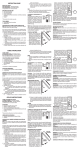
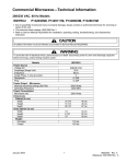
Commercial Microwave—Technical Information
208/230 VAC, 60 Hz Models
ASE70002
DQ22HSI2
KFC2SA2
RC17SD2OSI
RC22S2
RC30S2
MC23MPW2
P1332813M
P1332805M
P1332812M
P1332803M
P1332804M
P1332816M
P1332806M
ASE90002
KFC2W2
RC17S2
RC17SX
RC27S2
MC23MPTW2
WDYRC22
P1332814M
P1332811M
P1332801M
P1332802M
P1332815M
P1332807M
P1332808M
• Due to possibility of personal injury or property damage, always contact an authorized technician for servicing or
repair of this unit.
• Refer to Service Manual RS2240003 for installation, operating, testing, troubleshooting, and disassembly
instruction.
!
CAUTION
All safety information must be followed as provided in Service Manual RS2240003.
!
WARNING
To avoid the risk of electrical shock, personal injury or death; disconnect power to oven and discharge capacitor
before servicing, unless testing requires power.
Models
Power Source
Voltage AC
Amperage (Single
Unit)
Frequency
Single Phase, 3 wire
grounded
Receptacle
Plug
Power Output −
Microwave
Nominal microwave
energy (IEC705)
Operating Frequency
Power Consumption
Microwave only
Dimensions
Cabinet (in cm)
Width
Height
Depth
Oven Interior (in cm)
Width
Height
Depth
Weight
Uncrated
Crated
**
RC17S2
RC17SX
RC17SD2OSI
DQ22HSI2
RC22S2
ASE90002
RC30S2
RC27S2
KFC2W2
KFC2SA2
ASE70002
MC23MPTW2
MC23MPW2
208/230 VAC
20 A
208/230 VAC
20 A
208/230 VAC
30 A
208/230 VAC
30 A
208/230 VAC
20 A
208/230 VAC
20 A
60 Hz
X
60 Hz
X
60 Hz
X
60 Hz
X
60 Hz
X
60 Hz
X
6-20R
6-20P
6-20R
6-20P
6-30R
6-30P
6-30R
6-30P
6-20R
6-20P
**
**
1700 Watts
2200 Watts
3000 Watts
2700 Watts
2500 Watts
2000 Watts
2450 MHz
2450 MHz
2450 MHz
2450 MHz
2450 MHz
2450 MHz
2700 Watts
3200 Watts
4400 Watts
4100 Watts
3700 Watts
3200 Watts
19 1/4"
18 1/4"
26 1/4"
49 cm
46 cm
67 cm
19 1/4"
18 1/4"
26 1/4"
49 cm
46 cm
67 cm
19 1/4"
18 1/4"
26 1/4"
49 cm
46 cm
67 cm
19 1/4"
18 1/4"
26 1/4"
49 cm
46 cm
67 cm
19 1/4"
18 1/4"
26 1/4"
49 cm
46 cm
67 cm
19 1/4"
18 1/4"
26 1/4"
49 cm
46 cm
67 cm
13"
8 1/2"
15"
33 cm
22 cm
38 cm
13"
8 1/2"
15"
33 cm
22 cm
38 cm
13"
8 1/2"
15"
33 cm
22 cm
38 cm
13"
8 1/2"
15"
33 cm
22 cm
38 cm
13"
8 1/2"
15"
33 cm
22 cm
38 cm
13"
8 1/2"
15"
33 cm
22 cm
38 cm
94 lbs.
101 lbs.
94 lbs.
101 lbs.
115 lbs.
123 lbs.
115 lbs.
123 lbs.
115 lbs.
123 lbs.
115 lbs.
123 lbs.
MC23MPTW2, MC23MPW2 uses 20A Twist−Loc NEMA L6-20P plug
February 2006
©2006 Maytag Services
1
16026961
Component Testing Procedures
!
WARNING
To avoid risk of electrical shock, personal injury or death; disconnect power to oven and discharge capacitor
before servicing, unless testing requires power.
Illustration
Component
Thermal cutout
Test
Disconnect all wires from TCO.
Measure resistance across terminals.
Magnetron TCO ...................................
Cavity TCO ..........................................
Diode
Discharge Capacitor
Remove diode lead from capacitor and
connect ohmmeter.
Triac
Results
Open at 300°F (149°C) and
closed at 257°F (125°C)
Opens at 262°F (128°C)
Infinite resistance should be measured
in one direction and 50KΩ or more in
the opposite direction.
Reverse leads for second test.
NOTE: Ohmmeter must contain a
battery of 6 volts minimum.
Resistance Check
Disconnect wires to triac.
Caution - Do not operate oven with
wire to terminal MT2 removed.
MT2
MT1
GA TE
Triac 1 (center)
Triac 2 (left)
Triac 3 (right
Capacitor
Some units may use
more then one type of
capacitor. Refer to
Parts Manual for
correct capacitor
quantity.
Snubber assembly
Magnetron
Blower motor
Measure resistance from:
MT1 to MT2 .........................................
MT1 to Gate.........................................
MT2 to Gate.........................................
All terminals to ground .........................
Voltage Check
Measure voltage from:
MT1 to Gate
Discharge Capacitor
Remove wires from capacitor terminals
and connect ohmmeter, set on highest
resistance scale to terminals.
Between Terminals: Meter should
momentarily deflect towards zero then
return to over 5 MΩ. If no deflection
occurs, or if continuous deflection
occurs, replace capacitor.
Also check between each terminal and
capacitor case.
Disconnect wires to snubber.
Terminal to Case: Infinite resistance
Measure resistance across terminals ........
Infinite
Discharge Capacitor
Between Terminals: Less than 1 Ω
Remove wires from magnetron and
connect ohmmeter to terminals. Also
check between each terminal and ground.
Each terminal to ground measures
Infinite resistance.
Note: This test is not conclusive. If
oven does not heat and all other
components test good replace the
magnetron and retest.
Remove all wires from motor.
Measure resistance across coil .................
16026961
Infinite
Approximately 60 Ω
Infinite
Infinite
0.8 VAC when energized. If no
voltage, check H.V. board and wiring.
2
Approximately 25 Ω
February 2006
©2006 Maytag Services
Component Testing Procedures
!
WARNING
To avoid risk of electrical shock, personal injury or death; disconnect power to oven and discharge capacitor
before servicing, unless testing requires power.
Illustration
Component
Auto Transformer
Test
Discharge Capacitors
Remove all wires from terminals.
230
COM
0V
208
208 V
Measure resistance from:
230 V to 0 V ............................................
208 V to 0 V ............................................
120 V to 0 V ............................................
Discharge Capacitor
Remove all wires from terminals.
120
120 V
230 V
0
Transformer
6
COM
5
4
5
6
230
COM
208
208 VAC
230 VAC
4
Interlock switch
Door Closed
7
2
3 Secondary
4
5 Primary
8 Monitor
7
8
2
4
3
5
Measure resistance from:
230 to COM.............................................
208 to COM.............................................
230 to Ground .........................................
208 to Ground .........................................
Terminal 5 to 6 ........................................
Terminal 4 to Ground ..............................
Less than 1 Ω
Less than 1 Ω
Infinite
Infinite
Less than 1 Ω
Approximately 59 Ω
With door open measure resistance from:
Terminal 2 to 3 ........................................
Terminal 4 to 5 ........................................
Terminal 7 to 8 ........................................
Infinite
Infinite
Indicates continuity
With door closed measure resistance from:
Terminal 2 to 3 ........................................
Terminal 4 to 5 ........................................
Terminal 7 to 8 ........................................
Indicates continuity
Indicates continuity
Infinite
Lamp receptacle
(some models)
Test continuity of receptacle terminals.
Antenna motor
Remove all wires from terminals.
Power cord
Approximately 38 Ω
Approximately 37 Ω
Approximately 25 Ω
Disconnect wires to switch.
Measure resistance from:
Terminal to terminal ....................................
Refer to Parts Manual
for proper power cord
part number.
Results
Measure resistance of wires.
Indicates continuity if bulb is good
and screwed in.
Approximately 12K Ω
Continuity should be indicated on
each wire.
Verify polarity and grounding.
February 2006
©2006 Maytag Services
3
16026961
Component Testing Procedures
!
WARNING
To avoid risk of electrical shock, personal injury or death; disconnect power to oven and discharge capacitor
before servicing, unless testing requires power.
Illustration
Component
Side touch panel
Test
Continuity is indicated as 100 Ω and
below.
1
Top touch panel
Removal of touch panel is required to
perform test.
Continuity is indicated as 100 Ω and
below.
Pad
1
2
3
4
5
6
7
8
9
0
Start
Stop/Reset
Pad
Time Entry
Power Level
Stage
Program Save
Quantity
Menu
Hidden Pad
Results
Trace
3&5
3&6
3&7
3&8
3&9
4&5
4&6
4&7
4&8
4&9
5&6
6&9
Trace
5&7
5&8
5&9
6&7
6&8
7&9
8&9
Measurement
Continuity
Continuity
Continuity
Continuity
Continuity
Continuity
Continuity
Continuity
Continuity
Continuity
Continuity
Continuity
Measurement
Continuity
Continuity
Continuity
Continuity
Continuity
Continuity
Continuity
1
Display board
Pin 1
H.V. board
Connector
Interlock
Connector
J1
Side
Touch
Panel
Connector
Top
Touch
Panel
Connector
Pin 1
J6
Pin 1
J4
Pin 1
J5
A
Function
Test Set-Up
Input to Display
Board
At Display
Board
16026961
Test Points
Meter
Setting
Volts
B
Probe Placement
Test points A and B
4
Results
3.0 VAC
If voltage is present and no display is
indicated, replace display board.
If no voltage is present, check wire
harness connections and H.V. board.
February 2006
©2006 Maytag Services
Component Testing Procedures
!
WARNING
To avoid risk of electrical shock, personal injury or death; disconnect power to oven and discharge capacitor
before servicing, unless testing requires power.
H.V. board
Pin 1
E2
E3
E1
Pin 1
J1
J2
E4
E5
Pin 1
J3
Pin 28
J5
Pin 50
Pin 1
Pin 1
Pin 1
J6
J8
Pin 1
E7
J7
E6 J4
Pin 1
Function
Test Set-Up
Input to H.V. board
At H.V. board
Output to display
board
Disconnect
J5 connector,
blower runs
continuously
Meter
Setting
Volts
Volts
Probe Placement
J1 pin 1 (Brown wire)
& J1 pin 2 (White wire)
J5 pin 28 &
J5 pin 50
Results
Line voltage
- 24 VDC
NOTE: For the following test, place oven in Service Test Mode (see page 11).
Relay
Function
Test Set-Up
K1 at
230 VAC
line voltage
K2 at
208 VAC
line voltage
Blower motor
Antenna motor
Cavity light
Blower motor
Antenna motor
Cavity light
Disconnect
J2 connector
February 2006
©2006 Maytag Services
Disconnect
J2 connector
Meter
Setting
Ohms
Ohms
5
Probe Placement
Results
J1 pin 1 (Brown wire)
& J2 pin 4
Test mode 5 off − no continuity
Test mode 5 on − < 1 Ω
J1 pin 1 (Brown wire)
& J2 pin 3
Test mode 5 off − no continuity
Test mode 5 on − < 1 Ω
16026961
Component Testing Procedures
!
WARNING
To avoid risk of electrical shock, personal injury or death; disconnect power to oven and discharge capacitor
before servicing, unless testing requires power.
H.V. Board − Relay Test
Three Magnetron Models − ASE70002, ASE90002, KFC2W2, KFC2SA2, MC23MPTW2,
MC23MPW2, RC27S2, and RC30S2
Relay
Function
K8
Magnetron 1
(Top rear) at
230 VAC
Magnetron 1
(Top rear) at
208 VAC
All wires
connected to
H.V. board
All wires
connected to
H.V. board
Magnetron 2
(Top front) at
230 VAC
Magnetron 2
(Top front) at
208 VAC
All wires
connected to
H.V. board
All wires
connected to
H.V. board
Magnetron 3
(Bottom) at
230 VAC
Magnetron 3
(Bottom) at
208 VAC
All wires
connected to
H.V. board
All wires
connected to
H.V. board
K9
K4
K5
K6
K7
Test Set-Up
Meter
Setting
Probe Placement
Results
VAC
E2 (Black wire)
& J4 pin 2 (Red wire)
Test mode 1 off − line voltage
Test mode 1 on − 0 volts
VAC
E2 (Black wire)
& J4 pin 1 (White wire)
Test mode 1 off − line voltage
Test mode 1 on − 0 volts
VAC
E5 (Red wire)
& J3 pin 1 (Gray wire)
Test mode 2 off − line voltage
Test mode 2 on − 0 volts
VAC
E5 (Red wire)
& J3 pin 3 (Orange wire)
Test mode 2 off − line voltage
Test mode 2 on − 0 volts
VAC
J4 pin 4 (Black wire)
& J4 pin 6 (Black wire)
Test mode 3 off − line voltage
Test mode 3 on − 0 volts
VAC
J4 pin 4 (Black wire)
& J4 pin 5 (Brown wire)
Test mode 3 off − line voltage
Test mode 3 on − 0 volts
Two Magnetron Models − DQ22HSI2, RC17S2, RC17SD22, and RC22S2
Relay
Function
K8
Magnetron 1
(Top rear) at
230 VAC
Magnetron 1
(Top rear) at
208 VAC
All wires
connected to
H.V. board
All wires
connected to
H.V. board
Magnetron 3
(Bottom) at
230 VAC
Magnetron 3
(Bottom) at
208 VAC
All wires
connected to
H.V. board
All wires
connected to
H.V. board
K9
K6
K7
16026961
Test Set-Up
Meter
Setting
Probe Placement
Results
VAC
E5 (Red wire)
& J4 pin 2 (Red wire)
Test mode 1 off − line voltage
Test mode 1 on − 0 volts
VAC
E5 (Red wire)
& J4 pin 1 (White wire)
Test mode 1 off − line voltage
Test mode 1 on − 0 volts
VAC
J4 pin 4 (Black wire)
& J4 pin 6 (Black wire)
Test mode 3 off − line voltage
Test mode 3 on − 0 volts
VAC
J4 pin 4 (Black wire)
& J4 pin 5 (Brown wire)
Test mode 3 off − line voltage
Test mode 3 on − 0 volts
6
February 2006
©2006 Maytag Services
Component Testing Procedures
!
WARNING
To avoid risk of electrical shock, personal injury or death; disconnect power to oven and discharge capacitor
before servicing, unless testing requires power.
Three Magnetron Models
#3
#1
#2
#2
#1
#3
#2
#3
#1
#1
#3
#2
H.V. System # 1
Top Rear Magnetron
Center Transformer
Bottom Center Capacitor
Diode
Center Triac
February 2006
©2006 Maytag Services
H.V. System # 2
Top Front Magnetron
Left Transformer
Top Left Capacitor
Diode
Left Triac
7
H.V. System # 3
Bottom Magnetron
Right Transformer
Right Capacitor
Diode
Right Triac
16026961
Component Testing Procedures
!
WARNING
To avoid risk of electrical shock, personal injury or death; disconnect power to oven and discharge capacitor
before servicing, unless testing requires power.
Two Magnetron Models
#1
#1
#1
#3
#3
#3
#3
#1
H.V. System # 1
Top Rear Magnetron
Left Transformer
Top Capacitor
Diode
Left Triac
16026961
H.V. System # 3
Bottom Magnetron
Right Transformer
Bottom Capacitor
Diode
Right Triac
8
February 2006
©2006 Maytag Services
Power Testing Procedure
!
WARNING
To avoid risk of electrical shock, personal injury or death; disconnect power to oven and discharge capacitor
before servicing, unless testing requires power.
All Amana and Menumaster microwave oven power outputs are rated using the IEC705 standards. Using the IEC705
test method requires precision measurements and equipment that is not practical to be performed in the field. Using
the test shown below will indicate if the oven performance is satisfactory.
Test equipment required:
•
•
1000 ml test container and thermometer (Amana power test kit R0157397 Fahrenheit / Menumaster power
test kit M95D5 Celsius).
Digital watch / watch with a second hand for use on ovens with electromechanical timers.
Important Notes:
•
•
•
Low line voltage will cause low temperature rise / power output.
Ovens must be on a dedicated circuit, properly grounded, and polarized. Other equipment on the same
circuit may cause a low temperature rise / power output.
This test and results are not a true IEC705 test procedure and are only intended to provide servicers with an
easy means of determining if the microwave oven cooking output is correct.
Procedure
1. Fill the test container to the 1000 ml line with cool tap water.
NOTE:
Water temperature should be approximately 60°F / 16°C
2. Using the thermometer, stir water for five to ten seconds; measure, and record the temperature (T1).
3. Place test container of water in the center of oven cavity and close door.
4. Heat the water for a 33-second full power cycle.
NOTE:
Use a digital watch or a watch with a second hand for ovens with electromechanical timers.
5. At end of the cycle, remove test container. Using the thermometer, stir water for five to ten seconds and record
temperature (T2).
6. Subtract the starting water temperature (T1), from the ending water temperature (T2) to obtain the temperature
rise (∆T).
7. If the temperature rise (∆T) meets or exceeds the minimum, the test is complete. If the temperature rise (∆T)
fails to meet the minimum temperature rise, test the line voltage to verify it is correct. Then repeat steps 1 - 6
making sure to change the water. If the temperature rise (∆T) fails to meet the minimum temperature rise again
the oven will require service.
Minimum Temperature Rise at Thirty -Three (33) Seconds Run Time
∆T
(°F)
Cooking
Power Output
10 .................1000
11 .................1100
12 .................1200
14 .................1400
17 .................1700
18 .................1800
19 .................1900
February 2006
©2006 Maytag Services
∆T
(°F)
∆T
Cooking
Power Output
(°C)
20 ................. 2000
21 ................. 2100
22 ................. 2200
24 ................. 2400
25 ................. 2500
27 ................. 2700
30 ................. 3000
Cooking
Power Output
5 ............... 1000
5.5............. 1100
6.5............. 1200
7.5............. 1400
9.5............. 1700
10.............. 1800
10.5........... 1900
9
∆T
(°C)
Cooking
Power Output
11 ............ 2000
11.5 ......... 2100
12 ............ 2200
13 ............ 2400
13.5 ......... 2500
15 ............ 2700
16.5 ......... 3000
16026961
Display Diagnostics
!
WARNING
To avoid risk of electrical shock, personal injury, or death, disconnect power to oven and discharge capacitor
before servicing, unless testing requires power.
“CALL SERV”
―
Will appear in the display when there is a fault occurring with the unit. After servicing the unit,
the servicer must reset the service code to remove “CALL
ITEM STG QTY
C M
1
2
3
4
LMT PREHEAT NOT
POWER
SErv” from the display.
ITEM STG QTY
COOK
READY STANDBY LEVEL
C M
1
2
3
4
LMT PREHEAT NOT
POWER
COOK
READY STANDBY LEVEL
1 seconds ON
1 seconds ON
The display will then be OFF for 5 seconds
Unit must be in OFF condition
or
INITIAL power up mode.
Oven door must be closed.
Press Hidden Pad.
Display will indicate the Service Test Mode.
1. Enter Service Code by pressing the following pads in order shown:
HIDDEN pad, 1 pad, 3 pad, 5 pad, 7 pad, and 9 pad.
2. Press 0 pad to clear “CALL SErv” from the display. Display will indicate “C L r”.
3. Press STOP/RESET pad to exit Service Test Mode.
16026961
10
February 2006
©2006 Maytag Services
Diagnostics Procedures
!
WARNING
To avoid risk of electrical shock, personal injury or death; disconnect power to oven and discharge capacitor
before servicing, unless testing requires power.
!
CAUTION
All repairs as described in this troubleshooting section are to be performed only after the caution procedures one through
eight listed below have been followed.
1. Check grounding before checking for possible causes.
2. Be careful of the high voltage circuit.
3. Discharge high voltage capacitor.
4. When checking the continuity of the switches or the high voltage transformer, disconnect one lead wire from these parts
and then check continuity with the AC plug removed. To do otherwise may result in a false reading or damage to your
meter.
5. Do not touch any parts of the circuitry on the P.C. Board circuit since static electric discharge may damage this control
panel. Always touch yourself to ground while working on this panel to discharge any static charge in your body.
6. 208/230 VAC is present in the high voltage circuit board, power relay and primary circuit of low voltage transformer.
7. When troubleshooting, be cautious of possible electrical hazard.
Error Codes
During operation, the display may show the following service codes:
NOTE:
Display
Err1
Err2
Err3
Err4
Err5
Before scheduling service for any error codes, instruct customer to unplug oven for 1 minute,
reconnect power, and retest. If unit operates properly, no service call is required.
Description
Failed H.V. Board
Failed H.V. Board
Shorted Touch Panel
Shorted Display Board
Shorted Cable HV to Display Board
Failed H.V. Board
Failed H.V. Board
Shorted Touch Panel
Err6
HOT
Failed H.V. Board
Door
Door Interlock Primary Switch
CALL
SErv
Amperage monitoring System on H.V.
Board
Corrective Action
Replace H.V. board.
Replace H.V. board.
Replace Touch Panel.
Replace Display Board.
Replace Cable.
Replace H.V. board.
Replace H.V. board.
NOTE: If Touch Panel is pressed for more than 30 seconds, this error code
will appear.
1. Disconnect oven from power supply.
2. Disconnect side touch panel connector from display board (J5).
3. Reconnect oven to power supply.
4. If “Err5” reappears after 30 seconds, replace top touch panel.
5. If “Err5” does not reappear after 30 seconds, replace side touch panel.
Replace H.V. board.
•
•
•
•
•
•
•
•
•
•
•
•
•
•
February 2006
©2006 Maytag Services
Open TCO (magnetron).
Blower motor inoperative.
Restricted air filter.
H.V. board inoperative.
High ambient temperature.
Oven operated empty or with light loads.
Broken or loose wire.
Verify latch mechanism moves freely on door.
Verify J1 connector on display board is properly seated.
Test interlock switch assembly and perform door adjustment if necessary.
Replace interlock switch assembly.
Power interruption while oven is operating may cause this code to display
when power is restored.
Reset CALL SErv , Service Test procedure – Pad “0”
Place water load inside cavity and use pre-programmed pad to operate
oven for 30 seconds or more.
•
If CALL SErv does not appear, no further repairs are necessary.
•
If CALL SErv reappears, use Service Test procedure to operate each
H.V. system independently to isolate fault.
•
Replace H.V. Board If Call SErv display will not clear.
•
Reset CALL SErv after fault has been corrected.
11
16026961
Service Test
NOTE: Unit must be in OFF condition
or
INITIAL power up mode.
To Enter Service Test Mode, oven door must be closed.
NOTE: Pads will not beep when accessing Service Test Mode.
To EXIT Service Test Mode press STOP/RESET pad.
DQ22HSI and KFC2
MC units
ASE and RC units
REG MENU
MISC
Press Hidden Pad
as indicated above
on touch panels.
1
3
5
7
ITEM STG QTY
9
POWER
LMT
Component Evaluation
0 = Deactivated
1 = Activated
C
PREHEAT
High Voltage System # 1
READY
STANDBY
LEVEL
Displays actual Amperage,
will vary by model
1
Toggles Magnetron 1
(Top Rear) ON/OFF.
C
PREHEAT
READY
STANDBY
LEVEL
Timer counts up to 62 seconds and unit shuts off.
High Voltage System # 2
Displays actual Amperage,
will vary by model
2
Toggles Magnetron 2
(Top Front) ON/OFF.
C
PREHEAT
READY
STANDBY
LEVEL
Timer counts up to 62 seconds and unit shuts off.
NOTE: Not Applicable on Two Magnetron models:
DQ22HSI, MC24MP, MC24MPT, RC17S, RC17SD2, and RC22S.
Displays actual Amperage,
will vary by model
High Voltage System # 3
3
C
Toggles Magnetron 3
(Bottom) ON/OFF.
16026961
PREHEAT
READY
STANDBY
LEVEL
Timer counts up to 62 seconds and unit shuts off.
12
Indicates
Service
Mode
If no Amperage, check for line
voltage at H.V. transformer
primary winding.
If no voltage, check:
Interlock switch (secondary)
Triac 1
H.V. board (relay K8 if 230 VAC,
K9 if 208 VAC, and triac 1
drive voltage T1 - G)
Wiring
If voltage is present, check:
H.V. components and wiring.
If no Amperage, check for line
voltage at H.V. transformer
primary winding.
If no voltage, check:
Interlock switch (secondary)
Triac 2
H.V. board (relay K4 if 208 VAC,
K5 if 230 VAC, and triac 2
drive voltage T1 - G)
Wiring
If voltage is present, check:
H.V. components and wiring.
If no Amperage, check for line
voltage at H.V. transformer
primary winding.
If no voltage, check:
Interlock switch (secondary)
Triac 3
H.V. board (relay K6 if 230 VAC,
K7 if 208 VAC, and triac 3
drive voltage T1 - G)
Wiring
If voltage is present, check:
H.V. components and wiring.
February 2006
©2006 Maytag Services
Service Test
4
NOT ACTIVE
This mode is NOT active
with these models.
C
PREHEAT
READY
STANDBY
LEVEL
5
C M
PREHEAT
STANDBY
C M
This mode is NOT active
with these models.
LMT
LEVEL
QTY
7
C M
LMT
8
LEVEL
QTY
C M
LMT
LEVEL
QTY
9
C M
LMT
LEVEL
QTY
0
Pressing 0 will clear
CALL SERVICE display.
February 2006
©2006 Maytag Services
LEVEL
QTY
6
NOT ACTIVE
READY
If no fan operation, check:
Blower motor and wheel
Antenna motor
Cavity light (if applicable)
H.V. board relay K1 - 230 V
relay K2 - 208V
Wiring
C M
LMT
LEVEL
QTY
C M
LMT
LEVEL
13
CALL is displayed for 1 second
SErv is displayed for 1 second.
Then the display will be
OFF for 5 seconds.
This will continue until
Call Service is cleared
from the display.
16026961
Wiring Diagram and Schematic
!
WARNING
To avoid risk of electrical shock, personal injury or death; disconnect power to oven and discharge capacitor
before servicing, unless testing requires power.
12719301
DQ22HSI2
16026961
RC17S2
RC17SD2OSI
14
RC17SX
RC22S2
February 2006
©2006 Maytag Services
Wiring Diagram and Schematic
!
WARNING
To avoid risk of electrical shock, personal injury or death; disconnect power to oven and discharge capacitor
before servicing, unless testing requires power.
12719301
! DANGER
HIGH VOLTAGE
DQ22HSI2
February 2006
©2006 Maytag Services
RC17S2
RC17SD2OSI
15
RC17SX
RC22S2
16026961
Wiring Diagram and Schematic
!
WARNING
To avoid risk of electrical shock, personal injury or death; disconnect power to oven and discharge capacitor
before servicing, unless testing requires power.
12719101
ASE70002
MC23MPTW2
16026961
ASE90002
MC23MPW2
KFC2W2
RC27S2
16
KFC2SA2
RC30S2
WDYRC2
February 2006
©2006 Maytag Services
Wiring Diagram and Schematic
!
WARNING
To avoid risk of electrical shock, personal injury or death; disconnect power to oven and discharge capacitor
before servicing, unless testing requires power.
12719101
! DANGER
HIGH VOLTAGE
ASE70002
MC23MPTW2
February 2006
©2006 Maytag Services
ASE90002
MC23MPW2
KFC2W2
RC27S2
17
KFC2SA2
RC30S2
WDYRC2
16026961