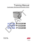
1
Commercial Microwave—Technical Information 208/230 VAC, 60 Hz Models WDYRC2 P1326305M, P1329111M, P1329603M, P1329615M • Due to possibility of personal injury or property damage, always contact an authorized technician for servicing or repair of this unit. • This technical sheet replace 16021599 Rev.1. • Refer to Service Manual RS2240003 for installation, operating, testing, troubleshooting, and disassembly instruction. ! CAUTION All safety information must be followed as provided in Service Manual RS2240003. ! WARNING To avoid the risk of electrical shock, personal injury or death: disconnect power to oven and discharge capacitor before servicing, unless testing requires power. Models Power Source Voltage AC Amperage (Single Unit) Frequency Single Phase, 3 wire grounded Receptacle Plug Power Output − Microwave Nominal microwave energy (IEC705) Operating Frequency Power Consumption Microwave only Dimensions Cabinet (in cm) Width Height Depth Oven Interior (in cm) Width Height Depth Weight Uncrated Crated January 2003 WDYRC2 208/230 VAC 20 A 60 Hz X 6−20R 6−20P 2000 Watts 2450 MHz 3200 Watts 19 1/4" 18 1/4" 26 1/4" 49 cm 46 cm 67 cm 13" 8 1/2" 15" 33 cm 22 cm 38 cm 115 lbs. 123 lbs. 1 16022042 Rev. 0 (Replaces 16021599 Rev. 1) Component Testing Procedures ! WARNING To avoid risk of electrical shock, personal injury or death: disconnect power to oven and discharge capacitor before servicing, unless testing requires power. Illustration Component Thermal cutout B5684124 .............. B5795306 .............. B8383102 Diode Test Disconnect all wires from TCO. Measure resistance across terminals. Magnetron TCO ................................... Cavity TCO .......................................... Discharge Capacitor Remove diode lead from capacitor and connect ohmmeter. D7681501 Triac Results Open at 300°F (149°C) and closed at 257°F (125°C) Opens at 262°F (128°C) Infinite resistance should be measured in one direction and 50KΩ or more in the opposite direction. Reverse leads for second test. NOTE: Ohmmeter must contain a battery of 6 volts minimum. Resistance Check Disconnect wires to triac. Caution - Do not operate oven with wire to terminal MT2 removed. MT2 MT1 GA TE Triac 1 (center) Triac 2 (left) Triac 3 (right 59001012Qty 3 10172901Q 10489402 12138106 Capacitor Snubber assembly Magnetron Blower motor Measure resistance from: MT1 to MT2 ......................................... MT1 to Gate......................................... MT2 to Gate......................................... All terminals to ground ......................... Voltage Check Measure voltage from: MT1 to Gate Discharge Capacitor Remove wires from capacitor terminals and connect ohmmeter, set on highest resistance scale to terminals. Between Terminals: Meter should momentarily deflect towards zero then return to over 5 MΩ. If no deflection occurs, or if continuous deflection occurs, replace capacitor. Also check between each terminal and capacitor case. Disconnect wires to snubber. Terminal to Case: Infinite resistance Measure resistance across terminals ........ Infinite Discharge Capacitor Between Terminals: Less than 1 Ω Remove wires from magnetron and connect ohmmeter to terminals. Also check between each terminal and ground. Each terminal to ground measures Infinite resistance. Note: This test is not conclusive. If oven does not heat and all other components test good replace the magnetron and retest. Remove all wires from motor. Measure resistance across coil ................. 16022042 Rev. 0 (Replaces 16021599 Rev. 1) Infinite Approximately 60 Ω Infinite Infinite 0.8 VAC when energized. If no voltage, check H.V. board and wiring. 2 Approximately 25 Ω January 2003 Component Testing Procedures ! WARNING To avoid risk of electrical shock, personal injury or death: disconnect power to oven and discharge capacitor before servicing, unless testing requires power. Illustration C8901509 Component Auto Transformer Test Discharge Capacitors Remove all wires from terminals. 230 COM 0V 208 208 V Measure resistance from: 230 V to 0 V ............................................ 208 V to 0 V ............................................ 120 V to 0 V ............................................ Discharge Capacitor Remove all wires from terminals. 120 120 V 230 V 10788613 0 Transformer 6 Approximately 38 Ω Approximately 37 Ω Approximately 25 Ω 5 5 COM Results 4 6 COM 230 208 208 VAC 230 VAC 12360506 / 59001114 4 Interlock switch Door Closed 7 2 3 Secondary 4 5 Primary 8 Monitor 7 8 2 Measure resistance from: 230 to COM............................................. 208 to COM............................................. 230 to Ground ......................................... 208 to Ground ......................................... Terminal 5 to 6 ........................................ Terminal 4 to Ground .............................. Less than 1.1 Ω Less than 1 Ω Infinite Infinite Less than 1 Ω Approximately 70 Ω Disconnect wires to switch. With door open measure resistance from: Terminal 2 to 3 ........................................ Terminal 4 to 5 ........................................ Terminal 7 to 8 ........................................ Infinite Infinite Indicates continuity With door closed measure resistance from: Terminal 2 to 3 ........................................ Terminal 4 to 5 ........................................ Terminal 7 to 8 ........................................ Indicates continuity Indicates continuity Infinite 4 3 5 B8371401 Lamp receptacle Test continuity of receptacle terminals. R0130263 Antenna motor Remove all wires from terminals. Measure resistance from: Terminal to terminal................................. R0131016 Power cord Measure resistance of wires. 12492202 Relay Measure resistance from: Terminal 0 to terminal 1 (coil) .................. Indicates continuity if bulb is good and screwed in. Approximately 12K Ω Continuity should be indicated on each wire. Verify polarity and grounding. 0 2 4 6 8 1 This relay contains a diode in the coil circuit. 0 2 January 2003 1 4 6 3 8 Approximately 6 to 7 MΩ NOTE: Analog meter is recommended for measurement. NOTE: If using a digital meter it must contain a battery of 6 volts minimum. 16022042 Rev. 0 (Replaces 16021599 Rev. 1) Component Testing Procedures ! WARNING To avoid risk of electrical shock, personal injury or death: disconnect power to oven and discharge capacitor before servicing, unless testing requires power. Top Touch Panel R0130113 P1326305M P1329111M P1329603M Switch Ribbon Trace Ribbon Trace 59001225 Hidden Pad 8 9 P1329615M To test touch panel for proper operation: 1. Identify ribbon traces for selected touch panel using chart. 2. Resistance between selected traces = 0 ohms. 3. Pressing touch panel, resistance between selected traces is less than 40 ohms. Hidden Pad Hidden Pad Pin 1 H.V. board Connector Interlock Connector J1 Side Touch Panel Connector Top Touch Panel Connector Pin 1 J6 Pin 1 J4 Pin 1 J5 1 Test Points A Side Touch Panel R0130111 B RibbonCable 1 S-1 P1326305M P1329111M P1329603M Ribbon Trace Switch Ribbon Trace S-2 59001226 S1 3 S-4 5 S-2 S-5 P1329615M Ribbon Cable To test touch panel for proper operation: 1. Identify ribbon traces for selected touch panel using chart. 2. Resistance between selected traces = 0 ohms. 3. Pressing touch panel, resistance between selected traces is less than 40 ohms. S-1 S-3 S2 S3 S4 S5 S6 S7 S8 S9 3 3 3 3 4 4 4 4 6 7 8 9 5 6 7 8 S10 S11 S12 4 6 5 9 9 6 1 BAG START PITA S-6 2 BAG PITA START S-7 S-3 S-4 S-8 S-12 1 DOZ BUN START S-9 2 D OZ BUN START S-10 REST ART S-11 S-5 S-6 BACON START S-8 S-12 Pin 1 S-7 1 DOZ START BUN S-9 2 DOZ BUN START S-10 RESTART S-11 H.V. board Connector Interlock Connector J1 Side Touch Panel Connector Pin 1 J6 Pin 1 J4 Pin 1 Top Touch Panel Connector J5 A 16022042 Rev. 0 (Replaces 16021599 Rev. 1) Test Points B 4 January 2003 Component Testing Procedures ! WARNING To avoid risk of electrical shock, personal injury or death: disconnect power to oven and discharge capacitor before servicing, unless testing requires power. Display board 12502401 Pin 1 H.V. board Connector Interlock Connector J1 Side Touch Panel Connector Pin 1 J6 Pin 1 J4 Pin 1 Top Touch Panel Connector J5 Test Points A Function Test Set-Up Input to Display Board At Display Board Meter Setting Volts B Probe Placement Test points A and B Results 3.0 VAC If voltage is present and no display is indicated, replace display board. If no voltage is present, check wire harness connections and H.V. board. H.V. Board − Relay Test Relay Function K8 Magnetron 1 (Top rear) at 230 VAC Magnetron 1 (Top rear) at 208 VAC All wires connected to H.V. board All wires connected to H.V. board VAC E2 (Black wire) & J4 pin 2 (Red wire) Test mode 1 off - line voltage Test mode 1 on - 0 volts VAC E2 (Black wire) & J4 pin 1 (White wire) Test mode 1 off - line voltage Test mode 1 on - 0 volts Magnetron 2 (Top front) at 230 VAC Magnetron 2 (Top front) at 208 VAC All wires connected to H.V. board All wires connected to H.V. board VAC E5 (Red wire) & J3 pin 1 (Gray wire) Test mode 2 off - line voltage Test mode 2 on - 0 volts VAC E5 (Red wire) & J3 pin 3 (Orange wire) Test mode 2 off - line voltage Test mode 2 on - 0 volts Magnetron 3 (Bottom) at 230 VAC Magnetron 3 (Bottom) at 208 VAC All wires connected to H.V. board All wires connected to H.V. board VAC J4 pin 4 (Black wire) & J4 pin 6 (Black wire) Test mode 3 off - line voltage Test mode 3 on - 0 volts VAC J4 pin 4 (Black wire) & J4 pin 5 (Brown wire) Test mode 3 off - line voltage Test mode 3 on - 0 volts K9 K4 K5 K6 K7 January 2003 Test Set-Up Meter Setting Probe Placement 5 Results 16022042 Rev. 0 (Replaces 16021599 Rev. 1) Component Testing Procedures ! WARNING To avoid risk of electrical shock, personal injury or death: disconnect power to oven and discharge capacitor before servicing, unless testing requires power. H.V. board 12559103Q P1326305M Pin 1 J8 59001120 P1329111M P1329603M P1329615M Pin 1 E1 J6 E3 E2 Pin 28 Pin 1 J5 Pin 50 J1 Pin 1 J7 Pin 1 Pin 1 J2 E7 E4 E6 E5 J4 J3 Pin 1 Function Test Set-Up Input to H.V. board At H.V. board Output to display board Disconnect J5 connector, blower runs continuously Meter Setting Volts Volts Pin 1 Probe Placement J1 pin 1 (Brown wire) & J1 pin 2 (White wire) J5 pin 28 & J5 pin 50 Results Line voltage - 24 VDC NOTE: For the following test, place oven in Service Test Mode (see page XX). Relay Function Test Set-Up K1 at 230 VAC line voltage K2 at 208 VAC line voltage Blower motor Antenna motor Cavity light Blower motor Antenna motor Cavity light Disconnect J2 connector 16022042 Rev. 0 (Replaces 16021599 Rev. 1) Disconnect J2 connector Meter Setting Ohms Ohms 6 Probe Placement Results J1 pin 1 (Brown wire) & J2 pin 4 Test mode 5 off - no continuity Test mode 5 on - < 1 Ω J1 pin 1 (Brown wire) & J2 pin 3 Test mode 5 off - no continuity Test mode 5 on - < 1 Ω January 2003 Component Testing Procedures ! WARNING To avoid risk of electrical shock, personal injury or death: disconnect power to oven and discharge capacitor before servicing, unless testing requires power. Three Magnetron Models #3 #1 #2 #2 #1 #3 #2 #3 #1 #1 #3 #2 H.V. System # 1 Top Rear Magnetron Center Transformer Bottom Center Capacitor Diode Center Triac January 2003 H.V. System # 2 Top Front Magnetron Left Transformer Top Left Capacitor Diode Left Triac 7 H.V. System # 3 Bottom Magnetron Right Transformer Right Capacitor Diode Right Triac 16022042 Rev. 0 (Replaces 16021599 Rev. 1) Power Testing Procedure ! WARNING To avoid risk of electrical shock, personal injury or death: disconnect power to oven and discharge capacitor before servicing, unless testing requires power. Power Test (Traditional Test Method) Test equipment required: Amana power test kit R0157397 (Fahrenheit) or Menumaster power test kit M95D5 (Celsius). 1. Fill the plastic container to the 1000 ml. line or Wendy’s plastic 1/9 x 4” deep pan with cool tap water. 2. Using the thermometer; stir the water, measure, and record the water temperature. Initial water temperature should be approximately 60°F (16°C). 3. Place container on the center of the oven shelf and heat the water for 33 seconds for ovens with more than 1550 watts. “2 BAG PITA”, “BACON” or “2 DOZ BUN” pads will allow enough time to complete the test. NOTE: Use a watch second hand, not the oven timer. 4. Stir the water, measure and record the temperature of the water after heating time is complete. 5. Subtract the starting water temperature (Step 2), from the ending water temperature (Step 4) to obtain the temperature rise (∆T). 6. See the Traditional Power Test Temperature Chart below. NOTES: •The IEC-705 test method requires precision measurements and equipment. It is not practical to perform the IEC test in the field. To convert the traditional power test results to the approximate IEC-705 rating, take the traditional power test results and add 100 watts per magnetron for the unit being tested. Example: 1682 watts output using the traditional power test for model WDYRC2 + 300 watts (3 magnetrons X 100 watts) 1982 Approximate IEC-705 results •Always perform power test three times for accuracy, changing the water after each test is performed. •Variation or errors in the test procedure will cause a variance in the temperature rise. Additional power tests should be made if temperature rise appears marginal. •Low line voltage will cause lower temperature rise. Traditional Power Test Temperature Chart THIRTY-THREE (33) SECONDS run time chart for units more than 1550 Watts cooking power Fahrenheit ∆T (°F) Cooking Power Output 16 ....... 1240 17 ....... 1317 18 ....... 1395 19 ....... 1472 20 ....... 1550 21 ....... 1627 22 ....... 1705 23 ....... 1782 16022042 Rev. 0 (Replaces 16021599 Rev. 1) Celsius ∆T (°F) ∆T (°C) Cooking Power Output 24 ........... 1860 25 ........... 1937 26 ........... 2015 27 ........... 2092 28 ........... 2170 28 ........... 2170 29 ........... 2247 30 ........... 2325 Cooking Power Output 11........ 1540 11.5..... 1610 12........ 1680 12.5..... 1750 13........ 1820 13.5..... 1890 8 ∆T (°C) Cooking Power Output 14 .............. 1960 14.5 ........... 2030 15 .............. 2100 15.5 ........... 2170 16 .............. 2240 16.5 ........... 2310 January 2003 Power Testing Procedure ! WARNING To avoid risk of electrical shock, personal injury or death; disconnect power to oven and discharge capacitor before servicing, unless testing requires power. Amana WDYRC Bun/Pita Warmer Performance Test for Store Personnel Use This test should be performed once a month or anytime unit performance is suspect. 1. Fill the plastic 1/9 x 4” deep pan used to hold bun bag clips with tap water. Do not use metal pan. 2. With an accurate digital thermometer probe, gently stir the water in the pan and write down the water temperature. Remove thermometer probe. 3. Position pan in center of oven. 4. Close the door and press the 2 DOZ BUN start button. 5. Immediately after the end of cycle tones begin, open the door and insert the digital thermometer probe into the water. 6. Gently stir the water in the pan until the maximum water temperature is observed (approximately 10-15 seconds). 7. Write down the maximum water temperature. 8. Subtract the initial water temperature reading from the last temperature reading. 9. If the temperature difference is greater then 44° F, the unit is performing within normal power tolerances. 10. If the temperature difference is less than 44° F, the unit may not be operating correctly. Do not continue to use this unit until a qualified service technician has looked at the unit and corrected any problem. January 2003 9 16022042 Rev. 0 (Replaces 16021599 Rev. 1) Display Diagnostics ! WARNING To avoid risk of electrical shock, personal injury, or death, disconnect power to oven and discharge capacitor before servicing, unless testing requires it. ! CAUTION All repairs as described in this troubleshooting section are to be performed only after the caution procedures one through eight listed below have been followed. 1. Check grounding before checking for possible causes. 2. Be careful of the high voltage circuit. 3. Discharge high voltage capacitor. 4. When checking the continuity of the switches or the high voltage transformer, disconnect one lead wire from these parts and then check continuity with the AC plug removed. To do otherwise may result in a false reading or damage to your meter. 5. Do not touch any parts of the circuitry on the P.C. Board circuit since static electric discharge may damage this control panel. Always touch yourself to ground while working on this panel to discharge any static charge in your body. 6. 208/230 VAC is present in the high voltage circuit board, power relay and primary circuit of low voltage transformer. 7. When troubleshooting, be cautious of possible electrical hazard. 8. When testing convection operation, convection fan may start at any time or if oven is hot. Error Codes During operation, the display may show the following service codes: NOTE: Before scheduling service for any error codes, instruct customer to unplug oven for 1 minute, reconnect power, and retest. If unit operates properly, no service call is required. Display Err1 Err2 Err3 Err4 Err5 Description Failed H.V. Board Failed H.V. Board Shorted Touch Panel Shorted Display Board Shorted Cable HV to Display Board Failed H.V. Board Failed H.V. Board Shorted Touch Panel Err6 HOT Failed H.V. Board Door Door Interlock Primary Switch 16022042 Rev. 0 (Replaces 16021599 Rev. 1) Corrective Action Replace H.V. Board. Replace H.V. board. Replace Touch Panel. Replace Display Board. Replace Cable. Replace H.V. board. Replace H.V. Board. NOTE: If Touch Panel is pressed for more than 30 seconds, this error code will appear. 1. Disconnect oven from power supply. 2. Disconnect side touch panel connector from display board (J5). 3. Reconnect oven to power supply. 4. If “Err5” reappears after 30 seconds, replace top touch panel. 5. If “Err5” does not reappear after 30 seconds, replace side touch panel. Replace H.V. board. • Open TCO (magnetron). • Blower motor inoperative. • Restricted air filter. • H.V. board inoperative. • High ambient temperature. • Oven operated empty or with light loads. • Broken or loose wire. • Verify latch mechanism moves freely on door. • Verify J1 connector on display board is properly seated. • Test interlock switch assembly and perform door adjustment if necessary. • Replace interlock switch assembly. 10 January 2003 Service Test ITEM STG QTY NOTE: Unit must be in OFF condition or INITIAL power up mode. C M 1 2 3 4 LMT POWER PREHEAT NOT READY STANDBY ITEM STG QTY C M 1 2 3 4 LMT COOK LEVEL POWER PREHEAT NOT READY STANDBY COOK LEVEL To Enter Service Test Mode, oven door must be closed. S1 S2 NOTE: Pads will not beep when accessing Service Test Mode. To EXIT Service Test Mode press STOP/RESET pad. S3 S4 S5 Accessing Service Test Mode ITEM STG QTY 1. Press Hidden pad, on top touch panel. 2. Press S1, S3, S5, S7, and S9 pads, on side touch panel. 3. Display indicates Service Test Mode. C M 1 2 3 4 BACON START COOK LMT PREHEAT NOT READY STANDBY LEVEL Hidden Pad ITEM STG QTY C M 1 2 3 4 LMT POWER PREHEAT NOT High Voltage System # 1 S1 Toggles Magnetron 1 (Top Rear) ON/OFF. Toggles Magnetron 2 (Top Front) ON/OFF. STANDBY COOK LEVEL ITEM STG QTY C M 1 2 3 4 POWER LMT PREHEAT NOT READY STANDBY COOK LEVEL Timer counts up to 62 seconds and unit shuts off. Displays actual Amperage, will vary by model ITEM STG QTY C M 1 2 3 4 POWER LMT PREHEAT NOT READY STANDBY COOK LEVEL Timer counts up to 62 seconds and unit shuts off. Displays actual Amperage, will vary by model High Voltage System # 3 ITEM STG QTY S3 C M Toggles Magnetron 3 (Bottom) ON/OFF. January 2003 1 2 3 4 LMT POWER PREHEAT NOT READY STANDBY COOK LEVEL Timer counts up to 62 seconds and unit shuts off. 11 S9 2 DOZ BUN START S10 RESTART S11 Component Evaluation Displays actual Amperage, will vary by model High Voltage System # 2 S2 READY 1 DOZ BUN START Indicates Service Mode Display Indication Press Pad S7 S8 S12 0 = Deactivated 1 = Activated S6 POWER If no Amperage, check for line voltage at H.V. transformer primary winding. If no voltage, check: Interlock switch (secondary) Triac 1 H.V. board (relay K8 if 230 VAC, K9 if 208 VAC, and triac 1 drive voltage T1 - G) Wiring If voltage is present, check: H.V. components and wiring. If no Amperage, check for line voltage at H.V. transformer primary winding. If no voltage, check: Interlock switch (secondary) Triac 2 H.V. board (relay K4 if 208 VAC, K5 if 230 VAC, and triac 2 drive voltage T1 - G) Wiring If voltage is present, check: H.V. components and wiring. If no Amperage, check for line voltage at H.V. transformer primary winding. If no voltage, check: Interlock switch (secondary) Triac 3 H.V. board (relay K6 if 230 VAC, K7 if 208 VAC, and triac 3 drive voltage T1 - G) Wiring If voltage is present, check: H.V. components and wiring. 16022042 Rev. 0 (Replaces 16021599 Rev. 1) Service Test Press Display Component Evaluation ITEM STG QTY S4 NOT ACTIVE C M 1 2 3 4 LMT POWER PREHEAT NOT READY STANDBY ITEM STG QTY S5 Toggles C M Blower Motor Antenna Motor(s) Cavity Light (if applicable) ON/OFF. 1 2 3 4 LMT READY STANDBY ITEM STG QTY S6 C M NOT ACTIVE 1 2 3 4 LMT Displays # of Magnetron Hours. C M 1 2 3 4 LMT PREHEAT NOT READY STANDBY Displays # of Door Cycles with a 1 to 1 ratio rounded to the nearest ten C M 1 2 3 4 LMT PREHEAT NOT READY STANDBY Clears Hours and Cycles (press START to activate) (Resets to 0). C M 1 2 3 4 LMT COOK LEVEL COOK LEVEL POWER PREHEAT NOT READY STANDBY ITEM STG QTY S9 This mode is NOT active with this model. POWER ITEM STG QTY S8 COOK LEVEL If no fan operation, check: Blower motor and wheel Antenna motor Cavity light (if applicable) H.V. board relay K1 - 230 V relay K2 - 208V Wiring POWER ITEM STG QTY S7 COOK LEVEL POWER PREHEAT NOT This mode is NOT active with this model. COOK LEVEL POWER PREHEAT NOT READY STANDBY COOK LEVEL NOTE: This will not appear on later production models. S10 Temperature OFFSET NOT APPLICABLE 16022042 Rev. 0 (Replaces 16021599 Rev. 1) ITEM STG QTY C M 1 2 3 4 LMT POWER PREHEAT NOT 12 READY STANDBY Temperature OFFSET is NOT applicable with this model. COOK LEVEL January 2003 Schematic ! WARNING To avoid risk of electrical shock, personal injury or death: disconnect power to oven and discharge capacitor before servicing, unless testing requires power. WDYRC2 January 2003 P1326305M 13 16022042 Rev. 0 (Replaces 16021599 Rev. 1) Wiring Diagram ! WARNING To avoid risk of electrical shock, personal injury or death: disconnect power to oven and discharge capacitor before servicing, unless testing requires power. WDYRC2 P1326305M ! DANGER HIGH VOLTAGE 16022042 Rev. 0 (Replaces 16021599 Rev. 1) 14 January 2003 Schematic ! WARNING To avoid risk of electrical shock, personal injury or death: disconnect power to oven and discharge capacitor before servicing, unless testing requires power. WDYRC2 January 2003 P1329111M 15 16022042 Rev. 0 (Replaces 16021599 Rev. 1) Wiring Diagram ! WARNING To avoid risk of electrical shock, personal injury or death: disconnect power to oven and discharge capacitor before servicing, unless testing requires power. WDYRC2 P1329111M ! DANGER HIGH VOLTAGE 16022042 Rev. 0 (Replaces 16021599 Rev. 1) 16 January 2003 Schematic ! WARNING To avoid risk of electrical shock, personal injury or death: disconnect power to oven and discharge capacitor before servicing, unless testing requires power. WDYRC2 January 2003 P1329603M, P1329615M 17 16022042 Rev. 0 (Replaces 16021599 Rev. 1) Wiring Diagram ! WARNING To avoid risk of electrical shock, personal injury or death: disconnect power to oven and discharge capacitor before servicing, unless testing requires power. WDYRC2 P1329603M, P1329615M ! DANGER HIGH VOLTAGE 16022042 Rev. 0 (Replaces 16021599 Rev. 1) 18 January 2003