1
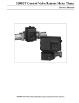
3200ET TIMER
Service Manual
IMPORTANT: Fill in pertinent information on page 2 for future reference.
3200ET Timer
Installation And Start-Up Procedures
Timer Programming
Water Hardness _________________________
System Capacity ________________________
Regeneration Time ______________________
Regeneration Cycle Step Programming
Step #1 _______________________________
Step #2 _______________________________
Step #3 _______________________________
Step #4 _______________________________
Step #5 _______________________________
Notes:
__________________________________________________________________________________________
__________________________________________________________________________________________
__________________________________________________________________________________________
1. Place the conditioner tank where you want to install the unit, making sure the tank is level and on a firm base.
2. During cold weather it is recommended that the installer warm the valve up to room temperature before operating.
3. All plumbing should be done in accordance with local plumbing codes. The pipe size for the drain, distributor size/
length, and Backwash flow rate should be set per specifications found in the valve service manual.
4. Lubricate the distributor O-ring seal and tank O-ring seal. Place the main control valve on tank. Note: Only use
silicone lubricant.
5. Solder joints near the drain must be done prior to connecting the Drain Line Flow Control fitting (DLFC). Leave at
least 6″ between the DLFC and solder joints when soldering pipes that are connected on the DLFC. Failure to do
this could cause interior damage to DLFC.
6. Teflon tape is the only sealant to be used on the drain fitting.
7. Make sure that the floor is clean beneath the salt storage tank and that it is level.
8. Place approximately 1″ of water above the grid plate. If a grid is not utilized, fill to the top of the air check in the salt
tank. Do not add salt to the brine tank at this time.
9. On units with a by-pass, place in by-pass position. Turn on the main water supply. Open a cold soft water tap
nearby and let run a few minutes or until the system is free from foreign material (usually solder) that may have
resulted from the installation. Once clean, close the water tap.
10. Place the by-pass in service position and let water flow into the mineral tank. When water flow stops, slowly open a
cold water tap nearby and let run until the air is purged from the unit. Then close tap.
11. Plug the valve into an approved power source. Once the valve is powered it will drive to the Service Position.
Page 2
Printed in U.S.A.
3200ET Timer
Installation And Start-Up Procedures (Cont’d.)
Service Indicator
Valve in Service
Manual Regeneration Tonight
- Arrow On
- Flashing Arrow
Time of Day Display Indicator
Reserve Indicator:
Volume Remaining Above Reserve
Volume Remaining At Or Below Reserve
- Arrow Off
- Arrow Flashing
Totalizer Display Indicator
Service
Time
Flow Indicator:
Reserve Totalizer Meter
Arrow Flashes With Water Flow
Regen Lockout Volume Program Flow Sensor
Remaining
Rate
Backwash
Low Battery
Brine/Rinse
Water Hardness
Rapid Rinse
System Capacity
Sensor Indicator:
Sensor Input Signal
Valid Regeneration Signal
- Flashing Arrow
- Arrow On
Flow Rate Display Indicator
Program Display Indicator
Tank Fill
Regeneration Time
Volume Remaining Display Indicator
Lockout Indicator:
Extra
Cycle
Totalizer
Flow
Rate
Program
Lockout Signal
S
E
T
- Arrow On
Regeneration Indicator
Valve In Regeneration
- Arrow On
12. Once the valve has reached Service normal operation is resumed. In Normal Operation the Time Of Day and, if
flow meter equipped, the Volume Remaining Displays will alternate being viewed. Set the Time Of Day Display by
depressing the Up or Down Set Button to the correct time. (See Fig. 1)
Service
For Example:
12:59 P.M.
(Valve in Service)
Time
Reserve Totalizer Meter
Regen Lockout Volume Program Flow Sensor
Remaining
Rate
13. Flow Meter Equipped Valves Only: The Volume Remaining Display is the volume of water (in gallons) remaining
prior to regeneration, including any reserve capacity. Without any water usage the Meter Arrow should be either off
or on but not changing. Open a soft water tap. The Meter Arrow should begin flashing at a rate that varies with flow
rate. Close the tap after 3 - 5 gallons of water flow.
For Example:
5 Gallons Of Water
Remaining
(Valve in Service)
(No water flow)
(Volume is below
reserve capacity,
Reserve arrow
flashing)
Service
Time
Reserve Totalizer Meter
Regen Lockout Volume Program Flow Sensor
Remaining
Rate
Service
Time
Reserve Totalizer Meter
Regen Lockout Volume Program Flow Sensor
Remaining
Rate
For Example:
0 Gallons Of Water
Remaining
(Valve in Service)
(Water flowing)
(Volume is below
reserve capacity,
Reserve arrow
flashing)
Page 3
Printed in U.S.A.
3200ET Timer
Installation And Start-Up Procedures (Cont’d.)
14. Manually initiate a regeneration cycle and allow water to run to drain for 3 to 4 minutes. Next, manually step the
valve through a regeneration cycle checking valve operation in each step.
A. Initiating Regeneration (Depending on the timer regeneration type you have one or two (2) Options):
1. Press and Release the Extra Cycle Button. With Immediate Regeneration Timers the control will go into
Regeneration immediately. With Delayed Regeneration Timers the Service Arrow will begin to flash immediately and a regeneration will occur at the preset regeneration time (i.e. 2:00 a.m.)
2. Press and Hold for 5 seconds the Extra Cycle Button. The control will go into Regeneration immediately.
B. Control Operation
1. During Regeneration: During Regeneration the control will display which regeneration step number the
valve is advancing to, or has reached, and the time remaining in that step.
For Example:
(Valve is advancing to Regeneration Step #1)
(#1 flashing)
(Regeneration arrow on)
Service
Time
Reserve Totalizer Meter
Backwash
Regen Lockout Volume Program Flow Sensor
Remaining
Rate
2. When the first cycle step is reached, a red LED will turn on to indicate the current regeneration cycle step.
For Example:
(Regeneration Step #1 has been reached)
(10.0 minutes remain in Step #1)
(Regeneration arrow on)
Service
Time
Reserve Totalizer Meter
Backwash
Regen Lockout Volume Program Flow Sensor
Remaining
Rate
3. Pushing the Extra Cycle Button during a regeneration step will immediately advance the valve to the next
regeneration step position.
4. Pushing the Up or Down Set Button during a regeneration step will adjust the time remaining in that current
regeneration step. Programmed regeneration step times will not be changed.
5. Once all regeneration cycle steps have been completed the valve will return to Service and resume normal
operation.
15. Manually step the valve to the Brine Draw position (see Step #14) and allow the valve to draw water from the brine
tank until it stops. Note: The air check will check at approximately the midpoint of the screened intake area.
16. Manually step the valve to the Brine Refill position and allow the valve to return to Service automatically.
17. Make sure the brine refill time (salt dosage) is set as recommended by the manufacturer.
18. With the valve in Service, check that there is about 1″ of water above the grid in the brine tank, if used.
19. Fill the brine tank with salt.
20. A 9V Alkaline Battery is recommended to be installed at all times for proper valve operation. The control will
indicate when the battery needs to be replaced by turning on the Low Battery LED.
Page 4
Printed in U.S.A.
3200ET Timer
Control Operation
Service Indicator
Valve in Service
Manual Regeneration Tonight
- Arrow On
- Flashing Arrow
Time of Day Display Indicator
Reserve Indicator:
Volume Remaining Above Reserve
Volume Remaining At Or Below Reserve
- Arrow Off
- Arrow Flashing
Totalizer Display Indicator
Service
Time
Flow Indicator:
Reserve Totalizer Meter
Arrow Flashes With Water Flow
Regen Lockout Volume Program Flow Sensor
Remaining
Rate
Backwash
Low Battery
Brine/Rinse
Water Hardness
Rapid Rinse
System Capacity
Sensor Indicator:
Sensor Input Signal
Valid Regeneration Signal
- Flashing Arrow
- Arrow On
Flow Rate Display Indicator
Program Display Indicator
Tank Fill
Regeneration Time
Volume Remaining Display Indicator
Lockout Indicator:
Extra
Cycle
Totalizer
Flow
Rate
Program
Lockout Signal
S
E
T
- Arrow On
Regeneration Indicator
Valve In Regeneration
- Arrow On
NORMAL CONTROL OPERATION
Flow Meter Equipped Delayed Regeneration Valves In Normal Operation the Time Of Day Display will alternate being viewed with the Volume Remaining Display. Water
flow through the unit is indicated by the Meter Arrow that will flash in a direct relationship to flow rate. As treated water
is used, the Volume Remaining Display will count down from a maximum value to the calculated reserve capacity. Once
this occurs, the Reserve Arrow will begin to flash as a indication that reserve capacity is being used. At the preset
Regeneration Time a regeneration cycle will then be initiated immediately.
For Example:
125 Gallons of Water Remaining
(Valve in Service)
(No water flow)
(Volume is below reserve capacity)
Service
Time
Reserve Totalizer Meter
Regen Lockout Volume Program Flow Sensor
Remaining
Rate
For Example:
0 Gallons of Water Remaining
(Valve in Service)
(Water flowing, Meter arrow flashing)
(Volume is below reserve capacity)
Service
Time
Reserve Totalizer Meter
Regen Lockout Volume Program Flow Sensor
Remaining
Rate
Page 5
Printed in U.S.A.
3200ET Timer
Control Operation (Cont’d.)
Timeclock Regeneration Valves In Normal Operation the Time Of Day Display will be viewed at all times. The control will operate normally until the days
since the last regeneration reaches the preset number of days. Once this occurs, a regeneration cycle will then be
initiated immediately at the preset Regeneration Time.
Flow Meter Equipped Immediate Regeneration Valves In Normal Operation the Time Of Day Display will alternate being viewed with the Volume Remaining Display. Water
flow through the unit is indicated by the Meter Arrow that will flash in a direct relationship to flow rate. As treated water
is used, the Volume Remaining Display will count down from a maximum value to zero. Once this occurs a regeneration
cycle will then be initiated immediately.
Service
Time
Reserve Totalizer Meter
For Example:
525 Gallons of Water Remaining
(Valve in Service)
(Water flowing, Meter arrow flashing)
Regen Lockout Volume Program Flow Sensor
Remaining
Rate
Sensor Immediate Regeneration Valves In Normal Operation the Time Of Day Display will be viewed at all times. The control will operate normally until a valid
sensor input signal is received. Once this occurs, a regeneration cycle will then be initiated immediately. The Sensor
Input Arrow will flash until the signal is determined to be valid.
Sensor Delayed Regeneration Valves In Normal Operation the Time Of Day Display will be viewed at all times. The control will operate normally until a valid
sensor input signal is received. Once this occurs, a regeneration cycle will then be initiated immediately at the preset
Regeneration Time. The Sensor Input Arrow will flash until the signal is determined to be valid. Then the Reserve
Arrow will begin to flash as a indication that reserve capacity is being used.
Service
Time
Reserve Totalizer Meter
For Example:
12:58 A.M. With Invalid Sensor Signal
(Valve in Service)
(Sensor arrow flashing)
Regen Lockout Volume Program Flow Sensor
Remaining
Rate
Service
Time
Reserve Totalizer Meter
For Example:
12:59 A.M. With Valid Sensor Signal
(Valve in Service)
(Sensor arrow on)
(Reserve arrow flashing) (Delayed Regen.)
Regen Lockout Volume Program Flow Sensor
Remaining
Rate
Immediate Regeneration Valves With Days Between Regeneration Override Set When the valve has reached its set Days Since Regeneration Override value a regeneration cycle will be initiated
immediately. This event occurs regardless of the Volume Remaining display having reached zero.
Delayed Regeneration Valves With Days Between Regeneration Override Set When the valve has reached its set Days Since Regeneration Override value a regeneration cycle will be initiated at the
preset Regeneration Time. This event occurs regardless of the Volume Remaining display having reached the
calculated reserve capacity.
Page 6
Printed in U.S.A.
3200ET Timer
Control Operation (Cont’d.)
CONTROL OPERATION DURING A POWER FAILURE
During a power failure all control displays will be turned off and regeneration cycles delayed. The control will otherwise
continue to operate normally until line power is restored or battery backup power is lost.
1. If battery backup power is never lost during a power outage, the control will continue to operate normally, without
the loss of data, until line power is restored.
2. If battery backup power is lost during a power outage, the control will store the current Time Of Day, Volume
Remaining, Regeneration Cycle Status, and various diagnostic displays. These stored displays will then be used
upon line power restoration until updated ones are created. To indicate this type of failure, the control will flash the
current. Time Of Day Display to indicate that this display and the Volume Remaining Display may not be correct.
CONTROL OPERATION DURING REGENERATION
In regeneration the control will display what regeneration step number the valve is advancing to, or has reached, and
the time remaining in that step. Once all regeneration cycle steps have been completed the valve will return to service
and resume normal operation.
1. First the Regeneration Arrow turns on. Then the display below is viewed to indicate that the valve is advancing to
the first regeneration cycle step.
Service
Time
Reserve Totalizer Meter
Backwash
For Example:
(Valve is advancing to Regeneration Step #1)
(#1 Flashing)
Regen Lockout Volume Program Flow Sensor
Remaining
Rate
2. When the first cycle step is reached, the display becomes as shown below. As time passes the control will begin to
decrement the step time in tenths of minutes until zero is reached. A red LED will also turn on to indicate the
current regeneration cycle step.
Service
Time
Reserve Totalizer Meter
Backwash
For Example:
(Regeneration Step #1 has been reached)
(10.0 minutes remain in Step #1)
Regen Lockout Volume Program Flow Sensor
Remaining
Rate
3. Once the step time reaches zero, the valve drive motor will turn on and the Regeneration Time Remaining Display
revert to all dashes until the next regeneration cycle step position is reached. Steps #2 and #3 will then be repeated
until all regeneration cycle steps have been completed and the valve has returned to Service.
4. Pushing the Extra Cycle Button during a regeneration cycle will immediately advance the valve to the next cycle
step position and resume normal step timing.
5. Pushing the Up or Down Set Button during a regeneration cycle will adjust the time remaining in a regeneration
cycle step. Actual regeneration cycle step programming will not be changed.
Page 7
Printed in U.S.A.
3200ET Timer
Control Operation (Cont’d.)
CONTROL OPERATION DURING PROGRAMMING
The control will only enter the Program Mode with the valve in Service and operating on line power. While in the
Program Mode the control will continue to operate normally monitoring water usage and keeping all displays up to date.
Control programming is stored in memory permanently with or without line or battery backup power.
LOCKOUT INPUT OPERATION
The Lockout Arrow will turn on whenever a Lockout Signal is being received by the control. Any requests for
regeneration will be delayed until this signal is removed. Regeneration will then proceed normally.
Keypad Operation
Extra
Cycle
Totalizer
Flow
Rate
Program
S
E
T
Extra Cycle Button
Pushing this button will initiate a regeneration cycle independently of actual valve conditions.
1. With immediate regeneration valves this extra regeneration will occur immediately.
2. With delayed regeneration valves this extra regeneration will occur at the set Regeneration Time. A regeneration
cycle can be forced to occur immediately by pushing and holding in for 5 seconds this button.
Totalizer/Flow Rate Button
This button is used to view the Totalizer and Flow Rate Displays. Depressing the button once will display flow rate.
Depressing the button again will display the total accumulation of water flow through the valve since it was last reset.
Depressing the button once more will return the display to Time Of Day or Volume Remaining. The Totalizer display is
reset by depressing and holding for 25 seconds this button. During the 25 seconds, the Totalizer Arrow will flash as an
indicator to the operator that the display is being reset properly.
Program Button
This button is used by the installer to program those settings indicated on the front panel by red LEDs.
Up Set Button
This button is used to set the current time of day, adjust time remaining in a regeneration cycle step and in valve
programming. The Up Arrow Button will increment a display setting.
Down Set Button
This button is used to set the current time of day, adjust time remaining in a regeneration cycle step and in valve
programming. The Down Arrow Button will decrement a display setting.
Low Battery Indicator
Low Battery
When the control is operating on line power, this red LED will turn on whenever the 9V Alkaline Battery (Not Included)
used for memory backup needs to be replaced. The battery is stored against the valve backplate. In the event of a
power outage the battery will maintain current operating displays for approx. 24 hours at maximum battery capacity.
Page 8
Printed in U.S.A.
Notes
Page 9
Printed in U.S.A.
3200ET Timer
3200ET Timer Assemblies
15
15
16
16
19
12
17
11
18
20
10
13
Standard 3/4″ To 2.0″
Electronic Flow Meter
Cap Assy.
Standard 3.0″
Electronic Flow Meter
Cap Assy.
9
4
8
7
2
6
5
3
1
Page 10
Printed in U.S.A.
3200ET Timer
3200ET Timer Assemblies Parts List
Item No.
Quantity
Part No.
1 . . . . . . . . . . . . 1 . . . . . . . . . . . . . 19144-02 . . . . . . . . . . . . . . .
19144-06 . . . . . . . . . . . . . . .
19144-05 . . . . . . . . . . . . . . .
19144-04 . . . . . . . . . . . . . . .
2 . . . . . . . . . . . . 1 . . . . . . . . . . . . . 18735 . . . . . . . . . . . . . . . . . .
3 . . . . . . . . . . . . 1 . . . . . . . . . . . . . 18741 . . . . . . . . . . . . . . . . . .
. . . . . . . . . . . . 1 . . . . . . . . . . . . . 18741-01 . . . . . . . . . . . . . . .
. . . . . . . . . . . . 1 . . . . . . . . . . . . . 18741-02 . . . . . . . . . . . . . . .
4 . . . . . . . . . . . . 1 . . . . . . . . . . . . . 27178-11 . . . . . . . . . . . . . . .
27178-13 . . . . . . . . . . . . . . .
27178-14 . . . . . . . . . . . . . . .
5 . . . . . . . . . . . . 1 . . . . . . . . . . . . . 18764 . . . . . . . . . . . . . . . . . .
6 . . . . . . . . . . . . 3 . . . . . . . . . . . . . 12758 . . . . . . . . . . . . . . . . . .
7 . . . . . . . . . . . . 1 . . . . . . . . . . . . . 18749 . . . . . . . . . . . . . . . . . .
8 . . . . . . . . . . . . 1 . . . . . . . . . . . . . 15159 . . . . . . . . . . . . . . . . . .
9 . . . . . . . . . . . . 1 . . . . . . . . . . . . . 18814 . . . . . . . . . . . . . . . . . .
10. . . . . . . . . . . . 1 . . . . . . . . . . . . . 17831-01 . . . . . . . . . . . . . . .
11. . . . . . . . . . . . 1 . . . . . . . . . . . . . . . . . . . . . . . . . . . . . . . . . . . .
12. . . . . . . . . . . . 1 . . . . . . . . . . . . . 14723 . . . . . . . . . . . . . . . . . .
13. . . . . . . . . . . . 2 . . . . . . . . . . . . . 10300 . . . . . . . . . . . . . . . . . .
40041-03 . . . . . . . . . . . . . . .
40041-04 . . . . . . . . . . . . . . .
40041-06 . . . . . . . . . . . . . . .
40043-01 . . . . . . . . . . . . . . .
40043-02 . . . . . . . . . . . . . . .
40043-03 . . . . . . . . . . . . . . .
19891 . . . . . . . . . . . . . . . . . .
14. . . . . . . . . . . . 4 . . . . . . . . . . . . . 17020 . . . . . . . . . . . . . . . . . .
Description
Assembly, Switch Pad - Standard Downflow
Assembly, Switch Pad - Upflow Variable Brining
Assembly, Switch Pad - Upflow Brine First
Assembly, Switch Pad - Standard Upflow
Screw, Hex Wash. #8 x 1 1/2
Housing, Circuit Board - No Hinge
Housing, Circuit Board - Right Hinge
Housing, Circuit Board - Left Hinge
24V 3200ET Circuit Board (Version 2.0 Software)
120V 3200ET Circuit Board (Version 2.0 Software)
240V 3200ET Circuit Board (Version 2.0 Software)
Shield, Circuit Board
Screw, Hex Washer #10 x 5/8
Bracket, Hinge (Not Used With 18741)
O-Ring .005
Spacer, Elect. Housing (Not Used With 18741)
Battery Clip
9V Alkaline Battery (Not Included)
Pin, Timer Hinge
Screw, Hex Washer #8 x 3/8
Harness Low Voltage 2750 with 3200ET
2510, 2750, 2850, 2900
Harness Low Voltage
3150 w/3200ET, 3150/3900
Harness Low Voltage
9000 w/3200ET, 9000/9500
Harness Power
2750/2900 w/3200ET, 2510/2750/2850/2900
Harness Power
3150/3900 w/3200ET
Harness Power
9000/9500 w/3200ET
Harness, Battery, All Valves
Screw, Slot Ind Hex, 6-20 x 3/8
Optional Electronic Flow Meter Cap Parts List
Item No.
Quantity
Part No.
15. . . . . . . . . . . . 1 . . . . . . . . . . . . . 19121-02 . . . . . . . . . . . . . . .
19121-03 . . . . . . . . . . . . . . .
19121-04 . . . . . . . . . . . . . . .
19121-05 . . . . . . . . . . . . . . .
16. . . . . . . . . . . .
17. . . . . . . . . . . .
18. . . . . . . . . . . .
19. . . . . . . . . . . .
20. . . . . . . . . . . .
1
4
1
6
1
. . . . . . . . . . . . . 17798 . . . . . . . . . . . . . . . . . .
. . . . . . . . . . . . . 12473 . . . . . . . . . . . . . . . . . .
. . . . . . . . . . . . . 14716 . . . . . . . . . . . . . . . . . .
. . . . . . . . . . . . . 12112 . . . . . . . . . . . . . . . . . .
. . . . . . . . . . . . . 14716-01 . . . . . . . . . . . . . . .
Description
Assy. Mtr. Cable 1.8 ft. 2500/9000/9500 System 4
Assy. Mtr. Cable 8 ft. All Valves Systems 6, 7
Assy. Mtr. Cable 25 ft. All Valves All
Systems (Optional)
Assy. Mtr. Cable 2.3 ft. 2750/2850/2900/3150/3900
Systems 4, 5, 9
Screw, Hex Washer
Screw, Hex Washer #10-24 x 5/8
Meter Cap Assy., Electronic
Screw, Hex Head
Meter Cap Assy., 3.0″ Electronic
Page 11
Printed in U.S.A.
3200ET Timer
3200ET System #4 - 1500/2500/2750/2850/3130/3150
System #4 - Single Unit Meter/Timeclock/Sensor Regeneration
Page 12
Printed in U.S.A.
3200ET Timer
3200ET - 9000/9500
Twin Unit Meter/Timeclock/Sensor Regeneration
Page 13
Printed in U.S.A.
3200ET Timer
3200ET System #4 - 2900/2930/3900
System #4 - Single Unit Meter/Timeclock/Sensor Regeneration
Page 14
Printed in U.S.A.
3200ET Timer
3200ET Systems #5 And #6 - 2750/2850/3130/3150
System #5:
2 Unit Individual Meter/Timeclock/Sensor
Interlocked Regeneration. Both Units in Service.
System #6:
2 Unit Single Meter/Timeclock/Sensor Series
Regeneration. Both Units in Service.
Page 15
Printed in U.S.A.
3200ET Timer
3200ET System #5 And #6 - 2900/2930/3900
System #5:
2 Unit Individual Meter/Timeclock/Sensor
Interlocked Regeneration. Both Units in Service.
System #6:
2 Unit Single Meter/Timeclock/Sensor Series
Regeneration. Both Units in Service.
Page 16
Printed in U.S.A.
3200 Timer
3200ET Systems #7/#8 (3-Way Solenoid Output) - 2750/2850/3130/3150
Page 17
Printed in U.S.A.
3200 Timer
3200ET Systems #7/#8 (4-Way Solenoid Output) - 2750/2850/3130/3150
Page 18
Printed in U.S.A.
3200 Timer
3200ET Systems #7 And #8 - 2900/2930/3900
Page 19
Printed in U.S.A.
3200ET Timer
3200ET System #9 (3-Way Solenoid Output) - 2750/2850/3130/3150
System #9:
Page 20
Printed in U.S.A.
2 Unit Individual Meter/Timeclock/Sensor
Alternator Regeneration. One Unit In Service,
The Other In Regeneration Or Standby
3200ET Timer
3200ET System #9 (4-Way Solenoid Output) - 2750/2850/3130/3150
System #9:
2 Unit Individual Meter/Timeclock/Sensor
Alternator Regeneration. One Unit In Service,
The Other In Regeneration Or Standby
Page 21
Printed in U.S.A.
3200ET Timer
3200ET System #9 - 2900/2930/3900
System #9:
Page 22
Printed in U.S.A.
2 Unit Individual Meter/Timeclock/Sensor
Alternator Regeneration. One Unit In Service,
The Other In Regeneration Or Standby
Notes
Page 23
Printed in U.S.A.
P/N 19487
Rev. 2 12/99
Printed 12/99