1
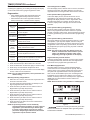
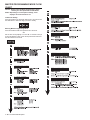
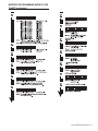
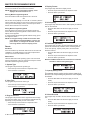
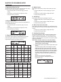
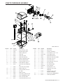
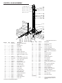
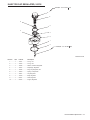
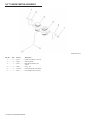
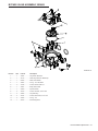
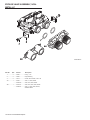
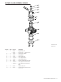
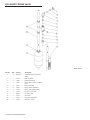
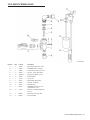
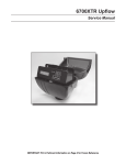
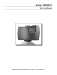
Fleck 6700XTR Upflow
Service Manual
TABLE OF CONTENTS
JOB SPECIFICATION SHEET
JOB SPECIFICATION SHEET................................................1
INSTALLATION.......................................................................2
TIMER OPERATION...............................................................2
MASTER PROGRAMMING MODE FLOW CHART................4
MASTER PROGRAMMING MODE.........................................6
USER PROGRAMMING MODE & FLOW CHART..................8
DIAGNOSTIC PROGRAMMING MODE FLOW CHART.........9
DIAGNOSTIC PROGRAMMING MODE ................................10
6700XTR POWERHEAD ASSEMBLY.....................................11
CONTROL VALVE ASSEMBLY...............................................12
INJECTOR CAP REGULATED, 20 PSI...................................13
3/4" TURBINE METER ASSEMBLY........................................14
BYPASS VALVE ASSEMBLY, BRASS.....................................15
BYPASS VALVE ASSEMBLY, NON-METALLIC......................16
BYPASS VALVE ASSEMBLY, BRASS.....................................17
2300 SAFETY BRINE VALVE.................................................18
2310 SAFETY BRINE VALVE.................................................19
TROUBLESHOOTING - TIMER..............................................20
TROUBLESHOOTING - CONTROL VALVE............................21
GENERAL SERVICE HINTS FOR METER CONTROL..........22
WATER CONDITIONER FLOW DIAGRAMS..........................23
VALVE WIRING DIAGRAM.....................................................25
SERVICE ASSEMBLIES.........................................................26
NOTE: Some options may not be available depending on valve model or
other options chosen.
Circle and/or fill in the appropriate data for future reference.
1. System Type:
A. Meter Immediate
B. Time Clock Delayed
C. Volume Override Delayed
D. Volume Override Immediate
E. Meter Delayed Weekly Reserve
F. Meter Delayed Variable Reserve
G. Meter Delayed Fixed Reserve
2. Valve Type:
A. 56XT/6700
B. Proprietary C
3. Regenerant Flow:
A. Downflow
B. Upflow
C. Downflow Double Backwash
D. Upflow Backwash
E. Filter
F. Upflow Variable Flow
4. Display Format:
A. U.S.
B. Metric (French Degrees, German Degrees, or PPM)
5. Unit Capacity:��������� Grains/French Degrees/German Degrees/PPM
6. Water Hardness:������� Grains/French Degrees/German Degrees/PPM
7. Capacity Safety Factor: Zero or______________________________%
8. Volume Override:_____________________________(Gallons or M3)
9. Regeneration Day Override:
A. Off
B. Every_______________________________________________ Days
10. Regeneration Time:
A. Delayed___________________________________________ AM/PM
B. Immediate
11. Regeneration Cycle:
A. Step #1 _ _ : _ _ : _ _
B. Step #2 _ _ : _ _ : _ _
C. Step #3 _ _ : _ _ : _ _
D. Step #4 _ _ : _ _ : _ _
E. Step #5 _ _ : _ _ : _ _
12. Media Volume:___________________________________ (CuFt or Liter)
13. Salt Dosage:____________________________ (lbs/CuFt or grams/Liter)
14. BLFC Size:______________________________________________ gpm
15. Auxiliary Relay:
A. Enabled
a. Auxiliary Relay Start 1 _ _ : _ _ : _ _
b. Auxiliary Relay End 1 _ _ : _ _ : _ _
c. Auxiliary Relay Start 2 _ _ : _ _ : _ _
d. Auxiliary Relay End 2 _ _ : _ _ : _ _
B. Disabled
16. Chemical Pump:
A. Enabled
B. Disabled
17. CPO Aux Relay Volume:__________________________ (Gallons or M3)
18. CPO Aux Relay: _ _ : _ _ : _ _
19. Flow Meter Size:
A. 0.75" Paddle
B. 0.75" Turbine
20. Generic Flow Meter for Maximum Flow Rate:
Add_____Gallons every _ _
42134 Rev H
JE11
INSTALLATION
Water Pressure
A minimum of 20 pounds (1.4 bar) of water pressure is required
for regeneration valve to operate effectively.
Electrical Facilities
An uninterrupted alternating current (A/C) supply is required.
Note: Other voltages are available. Please make sure your
voltage supply is compatible with your unit before installation.
11.Slowly place the by-pass in service position and let water
flow into the mineral tank. When water flow stops, slowly
open a cold water tap nearby and let run until the air is
purged from the unit.
12.Plug unit into an electrical outlet. Note: All electrical
connections must be connected according to local codes.
Be certain the outlet is uninterrupted.
Existing Plumbing
Condition of existing plumbing should be free from lime and
iron buildup. Piping that is built up heavily with lime and/or iron
should be replaced. If piping is clogged with iron, a separate
iron filter unit should be installed ahead of the water softener.
Location Of Softener And Drain
The softener should be located close to a drain to prevent air
breaks and back flow.
By-Pass Valves
Always provide for the installation of a by-pass valve if unit is
not equipped with one.
CAUTION Water pressure is not to exceed 125 psi (8.6 bar),
water temperature is not to exceed 110°F (43°C),
and the unit cannot be subjected to freezing
conditions.
Installation Instructions
1. Place the softener tank where you want to install the unit
making sure the unit is level and on a firm base.
2. During cold weather, the installer should warm the valve to
room temperature before operating.
3. All plumbing should be done in accordance with local
plumbing codes. The pipe size for residential drain line
should be a minimum of 1/2" (13 mm). Backwash flow rates
in excess of 7 gpm (26.5 Lpm) or length in excess of 20’
(6 m) require 3/4" (19 mm) drain line. Commercial drain
lines should be the same size as the drain line flow control.
4. Refer to the dimensional drawing for cutting height of the
distributor tube. If there is no dimensional drawing, cut the
distributor tube flush with the top of the tank.
5. Lubricate the distributor O-ring seal and tank O-ring seal.
Place the main control valve on tank. Note: Only use
silicone lubricant.
6. Solder joints near the drain must be done prior to
connecting the Drain Line Flow Control fitting (DLFC).
Leave at least 6" (15 cm) between the DLFC and solder
joints when soldering pipes that are connected on the
DLFC. Failure to do this could cause interior damage to the
DLFC.
7. Teflon tape is the only sealant to be used on the drain
fitting. The drain from twin tank units may be run through a
common line.
8. Make sure that the floor is clean beneath the salt storage
tank and that it is level.
9. Place approximately 1" (25 mm) of water above the grid
plate. If a grid is not utilized, fill to the top of the air check
(Figure 1) in the salt tank. Do not add salt to the brine tank
at this time.
10.On units with a by-pass, place in by-pass position. Turn on
the main water supply. Open a cold soft water tap nearby
and let run a few minutes or until the system is free from
foreign material (usually solder) that may have resulted
from the installation. Once clean, close the water tap.
2 • MY11 Fleck 6700XTR Upflow
60002 Rev E
Figure 1Residential Air Check Valve
TIMER OPERATION
Valve State
INI (Initializing)
INI will display on the screen for 30 to 45 seconds when
initializing after a power failure reset or programming.
RGQ (Regeneration Queued)
RGQ indicates that the reserve has been entered in a delayed
system and regeneration has been queued. When in service,
press the Extra Cycle button to toggle service (SRV) with RGQ.
Service (SRV)
SRV will display when the unit is in service.
LED Status Lights
Blue LED
Illuminates while the unit is in service and no errors exist. The
unit will always be in service unless a regeneration trigger has
occurred (green LED light will be displayed).
Green LED
Illuminates when the unit is in Regeneration mode, unless an
error condition exists.
Red LED
Illuminates when there is an error.
TIMER OPERATION continued
Flow Indicator
A rotating line (appearing as a rotating star shape) will display
on the screen when flow is going through the the meter.
Regeneration
• A time initiated control valve regenerates when the
number of programmed days has been reached
• A flow initiated control valve regenerates when the
volume count is zero or is below reserve capacity
System Type
Time Clock
Delayed
Meter
Immediate
Meter Delayed
Fixed Reserve
Regeneration Trigger
Day override parameter is reached
The time of day matches the regeneration day
override time
Regenerates as soon as the volume remaining
has been depleted
Volume remaining has been depleted to the fixed
reserve volume
The regeneration time has been reached
Meter Delayed
Variable
Reserve
Volume remaining has been depleted to the
variable reserve volume
Meter Delayed
Weekly
Reserve
Volume remaining has been depleted to the
weekly variable reserve volume
The regeneration time has been reached
The regeneration time has been reached
Volume
Override
Immediate
As soon as the programmed volume remaining
has been depleted from the tank
Volume
Override
Delayed
As soon as soon as the programmed volume
remaining has been depleted from the tank and
the regeneration time has been reached
Setting the Time of Day
1. Press and hold the Up or Down button for 2 seconds.
2. Press the Shift button to select the digit you want to modify.
3. Press the Up or Down buttons to adjust the value.
4. Press the Extra Cycle button to return to the normal display
screen, or after a 5 second timeout.
NOTE: The “D” button (Diagnostic) can be pressed to exit
without saving.
Manually Initiating a Regeneration
1. When timer is in service, press the Extra Cycle button for 5
seconds on the main screen.
2. The timer advances to Regeneration Cycle Step #1, and
begins programmed time count down.
3. Press the Extra Cycle button once to advance valve to
Regeneration Cycle Step #2 (if active).
4. Press the Extra Cycle button once to advance valve to
Regeneration Cycle Step #3 (if active).
5. Press the Extra Cycle button once to advance valve to
Regeneration Cycle Step #4 (if active).
6. Press the Extra Cycle button once to advance valve to
Regeneration Cycle Step #5 (if active).
7. Press the Extra Cycle button once more to advance the
valve back to in service.
NOTE: A queued regeneration can be initiated by
pressing the Extra Cycle button. To clear a queued
regeneration, press the Extra Cycle button again
to cancel. If regeneration occurs for any reason
prior to the delayed regeneration time, the manual
regeneration request shall be cleared.
Queued Regeneration (RGQ)
From the display screen, while the unit is in service, hold down
the Extra Cycle button until “RGQ” displays. The valve will
regenerate when the set regeneration time has been reached.
Timer Operation During Regeneration
In the main display screen, the timer shows the current
regeneration cycle and the time for that step. The green
LED light will display when the unit is in regeneration. Once
all regeneration steps are complete, the timer returns to
in service, displays a blue LED light, and resumes normal
operation.
Timer Operation During Programming
The timer enters program mode (unit must be in service).
While in the program mode the timer continues to operate
normally, monitoring water usage. Timer programming is stored
in memory permanently upon a normal exit from programming
mode.
Timer Operation During A Power Failure
All program settings are stored in permanent memory. Current
valve position, cycle step time elapsed, and time of day are
stored during a power failure, and will be restored upon power
re-application. Time is kept during a power failure, and time of
day is adjusted upon power up (as long as power is restored
within 12 hours).
NOTE: The time of day on the main display screen will
flash for 5 minutes when there has been a power
outage. The flashing of the time of day can be
stopped by pressing any button on the display.
Regeneration Day Override Feature
If the Day Override option is turned on and the valve reaches
the set Regeneration Day Override value, the Regeneration
Cycle starts at the programmed regeneration time.
Flow Meter Equipped Timer
As treated water is used, the Volume Remaining display
counts down from the calculated system capacity, less the
reserve volume. Once capacity reaches the reserve volume,
the system will regenerate based on the set regeneration
time. If set for an Immediate system, the unit will regenerate
immediately once it reaches zero capacity. If it is a Fixed,
Variable, or Weekly reserve, the unit will queue a regeneration
(RGQ) and count down Reserve Volume until the set
regeneration time.
NOTE: Reserve Volume is only available in a RGQ system.
Figure 2Volume Remaining (Less Reserve)
Figure 3
Transformer
must be grounded and ground wire
WARNING:
must be terminated to the backplate where grounding label is
located before installation.
Fleck 6700XTR Upflow MY11 • 3
MASTER PROGRAMMING MODE FLOW
CHART
Caution: Before entering Master Programming, please
contact your local professional water dealer.
Notes: Depending on current option settings, some
displays cannot be viewed or set.
To Set Time Of Day:
Press and hold the Up and Down buttons for 2 seconds. Press
the Shift button to select the digit you want to modify.
Entering Master Programming Mode.
Press and hold the Shift and Up buttons for 5 seconds.
OR
Set the Time of Day display to 12:01 P.M. or 12:01HR. Then go
to the main display screen, press the Up and Down buttons at
the same time for 5 seconds.
4 • MY11 Fleck 6700XTR Upflow
MASTER PROGRAMMING MODE FLOW
CHART continued
Fleck 6700XTR Upflow MY11 • 5
MASTER PROGRAMMING MODE
When the Master Programming Mode is entered, parameters
can be set to make the timer function as needed.
NOTE: Depending on current option settings, some
displays cannot be viewed or set.
Entering Master Programming Mode
Press and hold the Shift and Up buttons for 5 seconds.
OR
Set the Time of Day display to 12:01 P.M. or 12:01HR. (See the
User Programming section to learn how to set the Time of Day)
Then go to the main display screen, press the Up and Down
buttons at the same time for 5 seconds.
Exiting Master Programming Mode
Press the Extra Cycle button once per display until all are
viewed. Master Programming Mode is exited and the normal
display screen appears.
To exit the Master Programming Mode without saving, press
the Diagnostic button.
NOTE: If no keypad activity is made for 5 minutes while
in the Master Programming Mode, or if there is a
power failure, no changes will be made, and the
unit will go back to the main display screen.
Resets
Soft Reset
Press and hold the Up and Down buttons for 25 seconds until
12:00PM (or 12:00HR) appears. This resets all parameters
except for the flow meter totalizer volume.
Master Reset
Hold the Shift button while powering up the unit. This resets
all of the parameters in the unit. Check and verify the choices
selected in Master Programming Mode.
4. Display Format
This program step selects the display format.
• Press the Up or Down buttons to adjust this value.
• Press the Extra Cycle button.
5. Unit Capacity
This program step selects the timer’s total capacity of hardness
that can be removed.
• Press the Shift button to select the digit you want to
modify.
• Press the Up or Down buttons to adjust this value.
• Press the Extra Cycle button.
6. Feed Water (Hardness)
This program step is used to set the feed water hardness. The
system will automatically calculate volume remaining based
on the unit capacity, capacity safety factor, and feed water
hardness entered.
• Press the Shift button to select the digit you want to
modify.
• Press the Up or Down buttons to adjust this value.
• Press the Extra Cycle button.
NOTE: Feed Water Hardness will not be shown in Volume
Override or Time Clock system types.
1. System Type
This program step selects the system type.
• Press the Up or Down buttons to adjust this value.
• Press the Extra Cycle button.
2. Valve Type
This program step selects the valve type.
• Press the Up or Down buttons to adjust this value.
• Press the Extra Cycle button.
3. Regenerant Flow
This program step selects how the regenerant flows through
the tank (must match cam). The selections available will vary
depending on the previously chosen valve model.
• Press the Up or Down buttons to adjust this value.
• Press the Extra Cycle button.
6 • MY11 Fleck 6700XTR Upflow
7. Capacity Safety Factor
This program step is used to set the reserve capacity of
the unit. This is a percentage by which the unit’s capacity
is reduced.
• Press the Shift button to select the digit you want to
modify.
• Press the Up or Down buttons to adjust this value.
• Press the Extra Cycle button.
8. Volume Override
This program step is used to set the volume override of the
unit.
• Press the Shift button to select the digit you want to
modify.
• Press the Up or Down buttons to adjust this value.
• Press the Extra Cycle button.
MASTER PROGRAMMING MODE
continued
9. Regeneration Day Override
This program step sets the maximum amount of time (in days)
the unit can be in service without a regeneration.
• Press the Shift button to select the digit you want to
modify.
• Press the Up or Down buttons to adjust this value.
• Press the Extra Cycle button.
12. Media Volume
This program step sets the volume of the media in the resin
tank.
• Press the Shift button to select the digit you want to
modify.
• Press the Up or Down buttons to adjust this value.
• Press the Extra Cycle button.
13. Salt Dosage
10. Regeneration Time
This program step sets the time of day for the regeneration to
occur in delayed systems.
• Press the Shift button to select the digit you want to
modify.
• Press the Up or Down buttons to adjust this value.
• Press the Extra Cycle button.
This program step sets the salt dosage in the unit.
• Press the Shift button to select the digit you want to
modify.
• Press the Up or Down buttons to adjust this value.
• Press the Extra Cycle button.
14. Brine Line Flow Control Size
This program step allows the selection of the desired brine line
flow control size in the unit (must match physical brine line flow
control).
• Press the Up or Down buttons to adjust this value.
• Press the Extra Cycle button.
15. Auxiliary Relay Output
11. Regeneration Cycle Step Programming
This program step programs the Regeneration Cycle step
times 1 through 5. Please refer to the chart below for
regenerant flow default cycle steps and times.
Regenerant
Flow
Cycle
1
Time
Cycle 2
Time
Cycle 3
Time
Down Flow
Back
Wash
10 Min
Brine &
Slow Rinse
60 Min
Rapid
Rinse
10
Min
Back Wash
Filter
Back
Wash
15 Min
Draw
0
Settling
Rinse
10
Min
UF Back
Wash
Back
Wash
10 Min
Brine &
Slow Rinse
60 Min
Rapid
Rinse
10
Min
Down Flow
Double Back
Wash
Back
Wash
10 Min
Brine &
Slow Rinse
60 Min
Back
Wash
10
Min
Up Flow
Brine
Rinse
60
Back Wash
10
Rapid
Rinse
10
Min
Upflow
Variable Fill
Brine
Rinse
Variable
Pause
60 Min
Brine
Rinse
60
Min
Regenerant Flow
Cycle 4
Time
Cycle 5
Time
Down Flow
Brine
Tank Fill
12 Min
N/A
N/A
Back Wash Filter
Refill
0
N/A
N/A
UF Back Wash
Brine
Tank Fill
12 Min
N/A
N/A
Down Flow Double Back
Wash
Rapid
Rinse
10 Min
Brine Tank
Fill
12 Min
Up Flow
Brine
Tank Fill
12 Min
N/A
N/A
Upflow Variable Fill
Back
Wash
12 Min
Rapid Rise
10 Min
The next two displays are part of a series of settings used to
program the optional relay output. The first setting turns the
output on/off during regeneration only. The second turns the
output on during service only, every time a set volume of water
used has accumulated.
NOTE: When auxiliary outputs are in the OFF (default)
setting, press the Up or Down buttons to set the
first setting. Then press the Extra Cycle button to
advance to the second setting.
A. Timed Auxiliary Relay Output Window (Start & End Time
Setting)
This option setting consists of two displays. The first
display sets the turn-on time of the output, referenced
to the start of the first regeneration cycle. The second
display sets the output turn-off time, referenced again to
the start of the first regeneration cycle. An OFF setting
cancels this setting. All settings are in minutes and
output timing is synchronized with regeneration cycle
timing.
Start Time: Any time during regeneration.
End Time: At start time, and anytime during the
regeneration cycle.
Fleck 6700XTR Upflow MY11 • 7
MASTER PROGRAMMING MODE
continued
B. Chemical Pump Auxiliary Relay Output Window
This option setting consists of two displays. The first
display sets the volume of water flow at which the
output turns on. The second display sets the on time (in
seconds) of the output.
• Activate output after volume set is reached.
• Press the Shift button to select the digit you want to
modify.
• Press the Up or Down buttons to adjust this value.
• Press the Extra Cycle button.
USER PROGRAMMING MODE & FLOW
CHART
NOTE: Depending on current settings, some displays
cannot be viewed or set.
16. Flow Meter Size
This program step sets the size of the flow meter.
• Press the Up or Down buttons to adjust this value.
• Press the Extra Cycle button.
17. Maximum Flow Rate
This program step sets maximum flow rate of the generic flow
meter.
• Press the Shift button to select the digit you want to
modify.
• Press the Up or Down buttons to adjust this value.
• Press the Extra Cycle button.
18. Pulses per Gallon/Liter
This program step sets the pulses per gallon/liter for generic
flow meters.
• Press the Shift button to select the digit you want to
modify.
• Press the Up or Down buttons to adjust this value.
• Press the Extra Cycle button.
19.End of Master Programming Mode
Press the Extra Cycle button to save all settings and exit
Master Programming Mode.
1. Enter User Mode
• Press the Up or Down buttons for 5 seconds.
2. Set Feed Water Hardness
• Press the Shift, Up, and Down buttons to move the cursor
and change the value of the numbers.
• Press the Extra Cycle button to proceede to the next step.
NOTE: Feed Water Hardness will not be shown in
Volume Override or Time Clock system types.
3. Set Regeneration Day Override
• To turn on and set the days, press the Down button.
• Press the Shift, Up, and Down buttons to move the cursor
and change the value of the numbers.
• Press the Extra Cycle button to proceede to the next step.
4. Regeneration Time
• Press the Shift, Up, and Down buttons to move the cursor
and change the value of the numbers.
• Press the Extra Cycle button to proceede to the next step.
5. End of User Programming Mode
8 • MY11 Fleck 6700XTR Upflow
DIAGNOSTIC PROGRAMMING MODE
FLOW CHART
NOTE: Depending on current settings, some displays
cannot be viewed or set.
Entering Diagnostic Mode
1. Press and release the "D" button.
2. Press the Extra Cycle button once per display until all
displays are viewed and the normal display screen
appears.
3. Press and release the “D” button during this mode to exit
the Diagnostic Mode.
4. Depending on current option settings, some displays
cannot be viewed.
Fleck 6700XTR Upflow MY11 • 9
DIAGNOSTIC PROGRAMMING MODE
NOTE: Depending on current settings, some displays
cannot be viewed or set.
Overview Diagnostic Mode
8. Previous Day’s Water Usage
This program step displays the previous day’s water usage.
• Press the Extra Cycle button.
The current Diagnostic Programming Mode screen will display
until either the Extra Cycle button is pressed through for each
screen, or the Diagnostic button is pressed. In the event of
regeneration occurring while in the Diagnostic Programming
Mode, the regeneration step and time remaining will be
displayed. When regeneration completes, the display will return
to the normal time of day display screen.
9. Software Version
Entering and Exiting Diagnostic Mode
10. End of Diagnostic Programming Mode
Press and release the “D” button to enter the Diagnostic
Programming Mode. Pressing the Extra Cycle button will move
to the next diagnostic screen. Press the Extra Cycle button
once per display until all are viewed. Pressing the Diagnostic
button while in Diagnostic Mode will cause the unit to leave the
Diagnostic Mode and return to the normal time of day display
screen.
1. Current Flow Rate
This program step displays the calculated flow rate for the
timer. The below flow rates are the maximum flow rate the
timer will read for each meter.
.75” Paddle: 15 gpm (0.06 m3/m)
.75” Turbine: 15 gpm (0.06 m3/m)
• Press the Extra Cycle button.
2. Peak Flow Rate
This program step displays the peak flow rate (1 minute
average) since the last regeneration.
• Press the Extra Cycle button.
3. Totalizer
This program step displays the total volume of treated water
that passes through the meter.
• Reset to zero by holding the Up and Down buttons for five
seconds while in the totalizer screen.
• Press the Extra Cycle button.
4. Hours Between Last Two Regenerations
This program step displays the time between the last two
regenerations saved.
• Press the Extra Cycle button.
5. Hours Since Last Regeneration
This program step displays the hours since the last
regeneration.
• Press the Extra Cycle button.
6. Volume Remaining
This program step displays the volume remaining. The timer
will regenerate if the volume remaining is set to zero. The
maximum ranges are the same as the maximum volume
calculated on the main screen.
• Press the Extra Cycle button.
7. Reserve Capacity
This program step displays the reserve capacity, ensuring soft
water is available at all times.
• Press the Extra Cycle button.
10 • MY11 Fleck 6700XTR Upflow
This program step displays the timer’s software program
version number.
• Press the Extra Cycle button to exit.
NOTE: Diagnostic Programming Mode will stop if the
system goes into a regeneration.
6700XTR POWERHEAD ASSEMBLY
61501-6700 Rev C
Item No.
QTY
Part No.
Description
Item No.
QTY
Part No.
Description
1����������������1������� 15494-04�����������Drive Panel Assy, 6700
18��������������2������� 10218����������������Switch, Micro
2����������������1������� 17844����������������Bracket, Support, 6700
19��������������1������� 10302����������������Insulator, Limit Switch
3����������������1������� 13299����������������Washer, Spring, 3/8
20��������������2������� 17876����������������Screw, Phil Pan, 4-40 x 1 1/8
4����������������1������� 13017����������������Gear, Idler
21��������������1������� 17841-XXX�������Cover, Bottom, 6700
5����������������1������� 23045����������������Gear, Drive, 6700
22��������������1������� 13547����������������Strain Relief, Flat Cord
6����������������1������� 13175����������������Plate, Motor Mounting
23��������������1������� 16944����������������Motor Drive, 24V, 60 Hz, 2RPM
7����������������2������� 19080����������������Spring, Compression, 6700
24��������������3������� 11384����������������Screw, Phil, 6-32 x 1/4
8����������������2������� 13300����������������Ball, 1/4” Stainless Steel
25��������������4������� 17798����������������Screw, Slot Hex Hd
9����������������2������� 13296����������������Screw, Hex Wsh, 6-20 x 1/2
26��������������2������� 12473����������������Screw, Hex Wsh, 10-24 x 5/8
10��������������1������� 42933-10�����������Gear, Main Drive, Upflow
27��������������1������� 17845����������������Pin, Hinge, 6700
11��������������1������� 18722����������������Cam, Brine Valve, 6600/6700,
Blk
28��������������1������� 18679����������������Cap, Tapered, Black
29��������������1������� 17842-XX����������Cover, Top 6700
30��������������1������� 18615����������������Seal, Neoprene, .125
31��������������1������� 40981����������������Transformer, 24V, 9.6VA,
6700/7000
1������� 19025����������������Cam, Brine Valve, Variable
12��������������1������� 12037����������������Washer, Plain, #10
13��������������1������� 40214����������������Screw, Hex Wsh, 6-20 x 3/4
14��������������2������� 18754����������������Pin, 6700
15��������������1������� 19079����������������Washer, Friction
16��������������1������� 17885����������������Cam, Brining, 6600, U/F, Red
1������� 17919����������������Cam, Variable Brining, Gray
1������� 24598����������������Cam, Cycle U/F, Yellow
1������� 41086����������������Transformer, 24V, 9.6VA,
European, 6700/7000
32��������������1������� 42115����������������Harness Assy, 5066/6600/6700
33��������������1������� 42274����������������Timer Assy, 6700XTR
17��������������1������� 15151����������������Screw, Flat Head St, 6-20 x 3/4
Fleck 6700XTR Upflow MY11 • 11
CONTROL VALVE ASSEMBLY
61500-6600-6700 UF Rev B
Item No.
QTY Part No.
Description
1����������������1������� 19707-30�����������Valve Body, 5600 Upflow,
Bayonet
2����������������1������� 13255����������������Clip, Mounting
3����������������5������� 13242����������������Seal, 5600
4����������������1������� 13304����������������O-ring, -121
5����������������1������� 12281����������������O-ring, -338
6����������������4������� 14241����������������Spacer, 5600
7����������������1������� 14309����������������Retainer, Piston Rod
8����������������1������� 13030����������������Retainer, Dist Tube, O-ring
9����������������3������� 12112����������������Screw, Hex Hd Mach, 10-24 x
1/2
10��������������1������� 13302����������������O-ring, -014
11��������������1������� 10913-XX����������Nozzle, Injector (specify size)
12��������������1������� 10914-XX����������Throat, Injector (specify size)
13��������������1������� 11973����������������Spring, Brine Valve
14��������������1������� 11981-01�����������Ring, Retaining
15��������������1������� 12088����������������Washer, Flow 2.4 gpm
16��������������1������� 12550����������������Quad Ring, -009
17��������������1������� 12626����������������Seat, Brine Valve
18��������������1������� 12638����������������O-ring, -013, Injector
19��������������1������� 12977����������������O-ring, -015
20��������������1������� 13163����������������Body, Injector
21��������������1������� 13165����������������Cap, Brine Valve
22��������������1������� 13167����������������Spacer, Brine Valve
23��������������1������� 13172����������������Brine Valve Stem
24��������������1������� 13173����������������Retainer, DLFC Button
25��������������1������� 13244����������������Adapter, BLFC
26��������������1������� 13245����������������Retainer, BLFC
27��������������2������� 13301����������������O-ring, -011, Injector
28��������������1������� 13303����������������O-ring, -021
12 • MY11 Fleck 6700XTR Upflow
Item No.
QTY
Part No.
Description
29��������������1������� 13497����������������Disperser, Air, 5600
30��������������1������� 15348����������������O-ring, -563
31��������������1������� 16098����������������Washer, Nylon Brine
32��������������1������� 13302-01�����������O-ring, -014, 560CD
33��������������1������� 13296����������������Screw, Hex Wsh, 6-20 x 1/2
34��������������2������� 13314����������������Screw, Slot Ind Hex, 8-18 x .60
35��������������1������� 13363����������������Washer, Plain, .145 ID Stainless
Steel
36��������������1������� 13546����������������Retainer, End Plug
37��������������2������� 19228����������������Coupling, Adapter
38��������������4������� 13305����������������O-ring, -119
39��������������1������� 14067����������������Adapter, Upflow Brine
40��������������1������� 15449����������������Body, Regulator
41��������������1������� 14851����������������Cap, Regulator
42��������������1������� 17307����������������Washer, Flow, .125 gpm
43��������������2������� 15607����������������Screw, Hex Hd Mach, 10-24 x 1
3/8
44��������������1������� 15548����������������Screen, Pressure Regulator
45��������������1������� 23391����������������Seat, Regulator Spring
46��������������1������� 23393����������������Poppet, Regulator
47��������������1������� 14850����������������Spring, Compression
48��������������1������� 14846����������������Washer, Pressure Regulator
49��������������1������� 14847����������������Diaphragm, Regulator
50��������������1������� 14848����������������Ring, Slip, Regulator, Stainless
Steel
51��������������1������� 24602����������������Link, Piston Rod
52��������������1������� 15558����������������Rod, Piston, Upflow
Not Shown:
1������� 13301����������������O-ring, -001 (See "INJECTOR
CAP REGULATED, 20 PSI" on
page 13)
INJECTOR CAP REGULATED, 20 PSI
TORQUE - 9.0 IN-LBS 10%
7
6
9
5
3
4
8
1
2
TORQUE - 5.5 IN-LBS 10%
10
60286-20 Rev B
Item No.
QTY
Part No.
Description
1����������������1������� 13301����������������O-ring, -011
2����������������1������� 13303����������������O-ring, -021
3����������������1������� 14846����������������Washer, Pressure Regulator
4����������������1������� 14847����������������Diaphragm, Regulator
5����������������1������� 14848����������������Ring, Slip, Regulator, SS
6����������������1������� 14850����������������Spring, Compression
7����������������1������� 14851����������������Cap, Regulator
8����������������1������� 15449����������������Body, Regulator
9����������������1������� 23391����������������Seat, Regulator
10��������������1������� 23393����������������Poppet, Regulator
Fleck 6700XTR Upflow MY11 • 13
3/4" TURBINE METER ASSEMBLY
60626 Assy Rev A
Item No.
QTY
Part No.
Description
1����������������2������� 13314����������������Screw, Hex Washer, 8-18 x 5/8
2����������������2������� 19569����������������Clip, Flow Meter
3����������������1������� 19797����������������Meter Body Assembly, 3/4”
Turbine
4����������������4������� 13305����������������O-ring, 119
5����������������1������� 19791-01�����������Harness Assembly, Flow Meter
6����������������1������� 14613����������������Flow Straightener (not shown)
14 • MY11 Fleck 6700XTR Upflow
BYPASS VALVE ASSEMBLY, BRASS
60086 Rev D
Item No.
QTY
Part No.
Description
1����������������1������� 13874����������������Cap, Meter, Electronic
2����������������1������� 14715����������������Gear Assy, Electronic Meter Cap
3����������������1������� 41055����������������Plate, Intermediate
4����������������1������� 13847����������������O-ring, -137, Std, Meter
5����������������5������� 17798����������������Screw, Slot Hex Wsh Hd
6����������������1������� 13821����������������Body, Meter, 5600
7����������������1������� 13509����������������Impeller, Meter
8����������������4������� 12473����������������Screw, Hex Wsh, 10-24 x 5/8
9����������������4������� 13255����������������Clip, Mounting
10��������������4������� 13314����������������Screw, Slot Ind Hex, 8-18 x .60
11��������������4������� 13305����������������O-ring, -119
12��������������1������� 14613����������������Flow Straightener
Fleck 6700XTR Upflow MY11 • 15
BYPASS VALVE ASSEMBLY, NONMETALLIC
60049 Rev G
Item No.
QTY
Part No.
Description
1����������������2������� 13305����������������O-ring, -119
2����������������2������� 13255����������������Clip, Mounting
3����������������2������� 13314����������������Screw, Slot Ind Hex, 8-18 x .60
4A�������������1������� 18706����������������Yoke, 1”, NPT, Plastic
�������� 18706-02�����������Yoke, 3/4”, NPT, Plastic
4B�������������1������� 41027-01�����������Yoke, 3/4”, NPT, Cast, Machd
�������� 41026-01�����������Yoke, 1”, NPT, Cast, Machd,
Stainless Steel
16 • MY11 Fleck 6700XTR Upflow
BYPASS VALVE ASSEMBLY, BRASS
60040SS Rev R
60041 Rev T
Item No.
QTY
Part No.
Description
1����������������1������� 40614����������������Bypass Body, 3/4”
�������� 40634����������������Bypass Body, 1”, Stainless Steel
2����������������1������� 14105����������������Seal, Bypass, 560CD
3����������������1������� 11972����������������Plug, Bypass
4����������������1������� 11978����������������Plate, Bypass, Top
5����������������1������� 11979-02�����������Lever, Bypass, Black
6����������������1������� 11986����������������Plate, Bypass, Bottom
7����������������8������� 15727����������������Screw, Hex Wsh Hd, 10-24 x 1/2
8����������������1������� 13604-03�����������Label, Bypass, Standard Mount
�������� 13604-04�����������Label, Bypass, Reverse Mount,
Blue
9����������������1������� 40974����������������Washer, Plain, 3/8”
10��������������1������� 40973����������������Screw, Phil Hd, Indented Hex Hd
1/4-14 x .50
Fleck 6700XTR Upflow MY11 • 17
2300 SAFETY BRINE VALVE
60027 Rev D
Item No.
QTY
Part No.
Description
1����������������1������� 60027-00�����������Safety Brine Valve, 2300 Less
Elbow
2����������������1������� 10138����������������Ball, 3/8” Brass
3����������������1������� 11566����������������Ball Stop, Slow-Fill
4����������������1������� 10328����������������Fitting, Elbow, 90 Deg. 1/4 NPT x
3/8 T
5����������������2������� 10332����������������Fitting, Insert, 3/8
6����������������2������� 10330����������������Fitting, Sleeve, 3/8 Celcon
7����������������2������� 10329����������������Fitting, Tube, 3/8 Nut, Brass
8����������������1������� 10186����������������Nut, Hex, 10-32 Nylon
9����������������1������� 60002����������������Air Check, #500
10��������������1������� 10149����������������Rod, Float
11��������������1������� 10700����������������Float Assy, Blue/White
12��������������4������� 10150����������������Grommet, .30 Dia.
18 • MY11 Fleck 6700XTR Upflow
2310 SAFETY BRINE VALVE
42112 Rev A
Item No.
QTY
Part No.
Description
1����������������1������� 19645����������������Body, Safety Brine Valve, 2310
2����������������1������� 19803����������������Safety Brine Valve, Arm Assy
3����������������1������� 19804����������������Screw, Sckt Hd, Set, 10-24 x .75
4����������������1������� 19805����������������Nut, Hex, 10-24, Nylon Black
5����������������1������� 19652-01�����������Poppet Assy, SBV w/o O-ring
6����������������1������� 19649����������������Flow Dispenser
7����������������1������� 11183����������������O-ring, -017
8����������������1������� 19647����������������Elbow, Safety Brine Valve
9����������������2������� 19625����������������Nut Assy, 3/8” Plastic
10��������������1������� 18312����������������Retainer, Drain
11��������������1������� 60014����������������Safety Brine Valve Assy, 2310
(includes items 1-10)
12��������������2������� 10150����������������Grommet, .30 Dia (included with
item 13)
13��������������1������� 60068����������������Float Assy, 2310, w/30” Rod
14��������������1������� 60002����������������Air Check, #500
Fleck 6700XTR Upflow MY11 • 19
TROUBLESHOOTING - TIMER
If an error is detected, an error screen will alternate with the
main display screen every few seconds, and the LED light will
be Red.
During an error condition, the unit continues to monitor the
flow meter and update the remaining capacity. Once an
error condition is corrected, the unit returns to the operating
status it was in prior to the error, and regeneration resumes
according to normal programming. If an error is cleared by
reprogramming the unit in the Master Programming Mode,
the volume remaining may be reset to the full unit capacity
(as though it had just regenerated). If an error is present,
a regeneration can only occur manually by pressing and
holding the Extra Cycle button for 5 seconds. If the unit was
in regeneration when the error occurred, it will complete the
regeneration cycle and go into service.
When the problem is corrected, and the error no longer
displays (it may take several seconds for the unit to stop
displaying the error message), the unit will return to normal
operation. The LED light will no longer be Red, and will
turn Green if the unit is regenerating, or Blue if the unit is in
service.
Problem
Correction
Flashing/blinking
display
Power outage has occurred. Either wait 5
minutes for blinking to stop, or press any key
on the keypad.
Unit not responding
after going into
regeneration
Verify the unit is configured correctly
(ex: wiring valve type). Perform a Master
Reset by holding the Shift button and cycling
power. Check and verify the choices selected
in Master Programming Mode.
Unit displays
“ERROR CODE:
REPLACE UNIT”
(corrupted UAP)
Contact your local water treatment
professional
Error Codes
Error
Code
Display Message
Correction
01
ERROR CODE:
PROGRAM UNIT
Go through all screens in Master
Programming Mode.
02
ERROR CODE:
PROGRAM UNIT
Go through all screens in Master
Programming Mode.
03
ERROR CODE:
SERVICE UNIT
Perform a Master Reset by holding
the Shift button and cycling power.
Go through all screens in Master
Programming Mode. Manually initiate
a regeneration cycle by pressing the
Extra Cycle button for 5 seconds.
04
ERROR CODE:
SERVICE UNIT
Perform a Master Reset by holding
the Shift button and cycling power.
Go through all screens in Master
Programming Mode. Manually initiate
a regeneration cycle by pressing the
Extra Cycle button for 5 seconds.
05
ERROR CODE:
SERVICE UNIT
Call your local water treatment
professional as soon as possible.
Leave the unit running (do not
unplug).
NOTE: If the above corrections do not work, please
contact your local water treatment professional.
20 • MY11 Fleck 6700XTR Upflow
Error Display Screen Examples
TROUBLESHOOTING - CONTROL
VALVE
Problem
Cause
Correction
Water conditioner fails to
regenerate.
Electrical service to unit has been
interrupted
Assure permanent electrical service (check fuse,
plug, pull chain, or switch)
Timer is defective.
Replace timer.
Power failure.
Reset time of day.
By-pass valve is open.
Close by-pass valve.
No salt is in brine tank.
Add salt to brine tank and maintain salt level
above water level.
Injector screen plugged.
Clean injector screen.
Insufficient water flowing into brine tank.
Check brine tank fill time and clean brine line flow
control if plugged.
Hot water tank hardness.
Repeated flushings of the hot water tank is
required.
Leak at distributor tube.
Make sure distributor tube is not cracked. Check
O-ring and tube pilot.
Internal valve leak.
Replace seals and spacers and/or piston.
Improper salt setting.
Check salt usage and salt setting.
Excessive water in brine tank.
See "Excessive water in brine tank".
Iron buildup in line to water conditioner.
Clean line to water conditioner.
Iron buildup in water conditioner.
Clean control and add mineral cleaner to mineral
bed. Increase frequency of regeneration.
Inlet of control plugged due to foreign
material broken loose from pipes by recent
work done on plumbing system.
Remove piston and clean control.
Air in water system.
Assure that well system has proper air eliminator
control. Check for dry well condition.
Improperly sized drain line flow control.
Check for proper drain rate.
Iron in conditioned water.
Fouled mineral bed.
Check backwash, brine draw, and brine tank fill.
Increase frequency of regeneration. Increase
backwash time.
Excessive water in brine tank.
Plugged drain line flow control.
Clean flow control.
Plugged injector system.
Clean injector and screen.
Timer not cycling.
Replace timer.
Foreign material in brine valve.
Replace brine valve seat and clean valve.
Foreign material in brine line flow control.
Clean brine line flow control.
Drain line flow control is plugged.
Clean drain line flow control.
Injector is plugged.
Clean injector
Injector screen plugged.
Clean screen.
Line pressure is too low.
Increase line pressure to 20 psi
Internal control leak
Change seals, spacers, and piston assembly.
Service adapter did not cycle.
Check drive motor and switches.
Control cycles continuously.
Misadjusted, broken, or shorted switch.
Determine if switch or timer is faulty and replace it,
or replace complete power head.
Drain flows continuously.
Valve is not programming correctly.
Check timer program and positioning of control.
Replace power head assembly if not positioning
properly.
Foreign material in control.
Remove power head assembly and inspect bore.
Remove foreign material and check control in
various regeneration positions.
Internal control leak.
Replace seals and piston assembly.
Hard water.
Unit used too much salt.
Loss of water pressure.
Loss of mineral through drain
line.
Softener fails to draw brine.
Fleck 6700XTR Upflow MY11 • 21
GENERAL SERVICE HINTS FOR METER
CONTROL
Problem
Cause
Correction
Softener delivers hard water.
Reserve capacity has been exceeded.
Check salt dosage requirements and reset
program wheel to provide additional reserve.
Meter is not measuring flow.
Check meter with meter checker.
22 • MY11 Fleck 6700XTR Upflow
WATER CONDITIONER FLOW
DIAGRAMS
Brine/Slow Rinse Position
Cycle Step #1: Red Cam
Cycle Step #2: Yellow Cam
Cycle Step #3: Green Cam
Service Position
61500-56XT-6700 Upflow Rev A
61500-56XT-6700 Upflow Rev A
Backwash Position
Rapid Rinse
Cycle Step #1: Yellow Cam
Cycle Step #2: Red Cam
Cycle Step #4: Gray Cam
Cycle Step #3: Yellow Cam
Cycle Step #4: Red Cam
Cycle Step #5: Gray Cam
61500-56XT-6700 Upflow Rev A
61500-56XT-6700 Upflow Rev A
Fleck 6700XTR Upflow MY11 • 23
WATER CONDITIONER FLOW
DIAGRAMS continued
Brine Tank Fill Position
Cycle Step #1: Gray Cam
Cycle Step #4: Red Cam
Cycle Step #4: Yellow Cam
61500-56XT-6700 Upflow Rev A
Brine Making Position
Cycle Step #2: Gray Cam
61500-56XT-6700 Upflow Rev A
24 • MY11 Fleck 6700XTR Upflow
42139 Rev A
VALVE WIRING DIAGRAM
Fleck 6700XTR Upflow MY11 • 25
SERVICE ASSEMBLIES
Air Check:
60002-34��������������������Air Check, #500, 34" Long
Timer:
42274�������������������������Timer Assy, 6700XTR
Brine Line Flow Control:
60022-12��������������������BLFC, .125 GPM, 5000/5600/9000
60022-25��������������������BLFC, .25 GPM, 5000/5600/9000
60022-50��������������������BLFC, .50 GPM, 5000/5600/9000
60022-100������������������BLFC, 1.0 GPM, 5000/5600/9000
17307�������������������������Washer, Flow, .125 GPM
12094�������������������������Washer, Flow, .25 GPM
12095�������������������������Washer, Flow, .50 GPM
12097�������������������������Washer, Flow, 1.0 GPM
12977�������������������������O-ring, -015
13244�������������������������Adapter, BLFC
13245�������������������������Retainer, BLFC
60032�������������������������Brine Valve, 4600/5600
Yokes:
18706�������������������������Yoke, 1", NPT, Plastic
18706-02��������������������Yoke, 3/4", NPT, Plastic
41026-01��������������������Yoke, 1", NPT, SS
41027-01��������������������Yoke, 3/4" NPT
Bypass:
60040SS���������������������Bypass Assy, 3/4" NPT SS
60041SS���������������������Bypass Assy, 1" NPT SS
60049�������������������������Bypass Plastic Assy
Control Valve:
11973��������������������������Spring, Brine Valve
11981-01���������������������Ring, Retaining
12550�������������������������Quad Ring, -009
13165�������������������������Cap, Brine Valve
13167�������������������������Spacer, Brine Valve
13302�������������������������O-ring, -014
16098�������������������������Washer, Nylon Brine
13172�������������������������Brine Valve Stem
12626�������������������������Seat, Brine Valve
Floats:
60028-XX�������������������2300 Blue/White Float
60068-XX�������������������2310 Blue/White Float
Injector:
60084-XX�������������������Injector, Module Assembly
Meter:
60086-50��������������������Meter Assy, 3/4", Electronic
Pistons:
60102-62��������������������Piston Assy, 6600/6700, Upflow
14309�������������������������Retainer, Piston Rod
13001-03��������������������Piston Rod Assy, 6600, Upflow
15561�������������������������End Plug Assy, 6600
18848�������������������������Piston, 6600, Upflow
Safety Brine Valve:
60014�������������������������2310 Safety Brine Valve Assy
60027-FFA������������������2300 Safety Brine Valve Assy
60027-FFS�����������������2300 Safety Brine Valve Assy
Seal & Spacer Kit:
60125�������������������������Seal & Spacer Kit, 5600/9000 Top
13242�������������������������Seal, 5600
14241�������������������������Spacer, 5600
26 • MY11 Fleck 6700XTR Upflow
Fleck 6700XTR Upflow MY11 • 27
© 2011 Pentair Residential Filtration, LLC 42134 Rev H
JE11