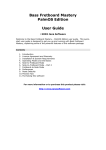
1
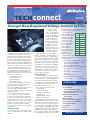
May/June 2005
Volume 12, No.3
Charge! New Regulated Voltage Control System
Traditional charging systems use an internal
temperature sensor inside the generator to
establish generator voltage set points. When
the generator is cold, it raises the voltage output set point. When the generator is hot, it
lowers the voltage output set point. This type of
system tends to overcharge the battery on long
trips at highway speeds and undercharge the
battery on short trips with low vehicle speeds.
Regulated Voltage Control (RVC) is a new
dynamic control of the vehicle’s system voltage. It regulates the generator’s output voltage, based mainly on estimated battery temperature and battery state-of-charge. The main
benefits of this system are:
• Improved fuel economy
• Extended battery life
• Extended lamp life
• Extended switch life
GM is using three different generations of
RVC systems on a number of new models,
including Cadillac CTS, SRX and STS,
Chevrolet and GMC full-size trucks and SUVs,
Chevrolet Cobalt and Uplander, Buick
LaCrosse and Terazza, and Pontiac Grand Prix
and Montana SV6.
Since the RVC system allows changes to
vehicle voltage, up or down, under various
scenarios — the battery state of charge and
the vehicle’s present electrical needs are two
conditions taken into account — the voltmeter
may fluctuate. Conventional systems usually
maintain a consistent reading of 14 volts. The
fluctuation of the RVC system may range
between 12 and 14 volts. This is normal system operation.
Two RVC Systems
There are two types of RVC systems used
today — integrated RVC and stand-alone RVC
(SARVC).
Integrated systems
use a battery current
sensor to provide a body
control module (BCM)
the amount the battery is
charging or discharging.
Accurate voltage measurements are taken
through the battery positive voltage and ignition
1-voltage circuits. The
BCM then communicates information over
serial data circuits for the
ECM/ PCM to directly
control the generator.
SARVC systems do not use the BCM for
operation. They have a generator battery control module mounted to the negative battery
cable, to interpret battery current, and voltage
and battery temperature inputs. The battery
current sensor is internal to the module. This
module also directly controls the generator Lterminal duty cycle instead of the ECM/PCM.
Both types of system have two types of
corrective actions to insure the battery stays
at an 80% state of charge. These include up
to three levels of load shed and up to three
levels of idle boost operation.
System Operation
The basic operation of the RVC system is
covered here, but not all systems will enter all
modes of operation; refer to the applicable
service manual information for more details.
The purpose of the RVC system is to maintain the battery state-of-charge at 80% or
above and support vehicle loads.
The six modes of operation include:
• Charge Mode
• Fuel Economy Mode
• Voltage Reduction Mode
• Start Up Mode
• Windshield De-ice Mode
• Battery Sulfation Mode
The PCM/ECM (generator battery control
module on full-size trucks) controls the generator through the generator L-terminal control
circuit. It monitors the generator performance
though the generator field duty cycle signal circuit. The signal is a 5 volt PWM (pulse width
modulated) signal of 128 Hz with a duty cycle
of 0-100%. Normal duty cycle is between 595%. The ranges between 0-5% and 95-100%
are for diagnostic purposes. The accompany1
ing table shows the commanded duty cycle
and output voltage of the generator.
The generator proDuty Generator
vides a feedback signal
Voltage
Cycle
of the generator load
Set Point
through the generator
10%
11.0V
field duty cycle signal
20%
11.56V
circuit to the control
30%
12.12V
module. The signal is
a 5 volt PWM signal of
40%
12.68V
128 Hz, with a duty
50%
13.25V
cycle of 0-100%.
60%
13.81V
Normal duty cycle is
70%
14.37V
between 5-99%. The
ranges between 0-5%
80%
14.94V
and 100% are for
90%
15.5V
diagnostic purposes.
Charge Mode – The control module enters
Charge Mode whenever one of the following
conditions is met:
• Under WOT conditions and when the fuel
rate (sent by the ECM/PCM) is greater
than 21 g/s and the throttle
position is greater than 90%.
• The headlamps are on, low or high beam.
• The wipers are on for more than
8 seconds.
• The electric cooling fans are on
high speed.
• The rear defogger is on.
• The Battery SOC (state of charge)
is less than 80%.
continued on page 3
IN THIS ISSUE
New Regulated Voltage Control System . .1
Fuel Tank Module/
Fuel Pump Module Connector . . . . . . . .2
Incorrect Placement of Inboard and
Outboard Brake Pads . . . . . . . . . . . . . . .2
DEX-COOL and Conventional
Engine Coolant . . . . . . . . . . . . . . . . . . . . .4
Measuring Coolant . . . . . . . . . . . . . . . . . . . .4
Vehicle Service Contract Program . . . . . . .5
Keeping Current in Air Conditioning . . . . .5
Service Advisor Seminar . . . . . . . . . . . . . . .6
Sports Report . . . . . . . . . . . . . . . . . . . . . . . . .6
Tech Tips . . . . . . . . . . . . . . . . . . . . . . . . . . . . .7
Tell Us about Your TechConnect . . . . . . . . .8
acdelcotechconnect.com
Replace the Connector When Replacing
Fuel Tank Module/Fuel Pump Module
Anytime the fuel tank module/fuel pump module is replaced on 1999-2003 Cadillac
Escalade; 1996-2001 Chevrolet Suburban, GMC Suburban and GMC Yukon XL; 19962003 Chevrolet Silverado, Chevrolet Tahoe, GMC Sierra and GMC Yukon models
(excludes 2003 E85 flexible fuel vehicles and diesel vehicles), the Metri-Pack 150 connector (ACDelco part number PT2054) also should be replaced.
It’s important to note that not all vehicles use the
Metri-Pack 150 connector. This information does not
apply to vehicles equipped with the GT 280 connector.
The Metri-Pack 150 connector should be replaced
because any residual damage to the connector may
result in a voltage drop across the module, which can
lead to repeat failures.
When replacing the connector, be sure to use the
splice sleeves provided
due to the exposure
to moisture.
Refer to ACDelco
bulletin 05D-J-069,
which revises ACDelco
bulletin 05D-J-052, for
more information.
– Thanks to
Metri-Pack 150 Connector
GT 280 Connector
Dennis Kissack
Possible Incorrect Placement of
Inboard and Outboard Brake Pads
ACDelco TechConnect is published
bi-monthly for retail technicians to
provide timely service information,
increase knowledge and improve
the performance of the service
center.
Publisher & Editor:
Greg Baker
ACDelco
E-mail /
[email protected]
Technical Editors:
Mark Spencer
E-mail /
[email protected]
Jim Horner
E-mail /
[email protected]
Desktop Publishing:
Greg Szpaichler, MediaWurks
E-mail /
[email protected]
Write to: *
ACDelco TechConnect
P.O. Box 500
Troy, MI 48007-0500
:
On the Web:
acdelcotechconnect.com
The inboard pad, right, on the 17D-727 brake pad set can be identified
by a taller center-positioning tab and the wear indicator.
The inboard brake pad on 17D-727
brake pad sets can be installed in the outboard position on 1997-2005 Chevrolet
Malibu; 1997-1999 Oldsmobile Cutlass;
and 1999-2004 Oldsmobile Alero and
Pontiac Grand Am models.
The incorrect placement of the inboard
pad in the outboard position on this
design of caliper may result in caliper
slide movement, rapid pad wear, possible
binding and overheating of the brakes. If
the pads are incorrectly placed, the
caliper sliding action will be restricted and
pad to rotor contact will always be present, contributing to pad wear and noise.
The outboard pad will not easily install in
the outward mounting bracket ears, but it
can be forced into position.
Unlike many pads that have the wear
indicator mounted on the outboard pad,
the wear indicator clip on the 17D-727
pad sets is installed on the pad that is
mounted inboard.
There are several differences that can
be noted to identify the inboard pad from
the outboard pad. The inboard pad with
the wear indicator on these pad sets has
a taller center-positioning tab than the
outboard tab. The inboard pad also has a
thicker metal backing and a thinner friction block than the outboard pad.
When installing the pads, do not grind
the length of the center-mounting tab
enable the wrong pad to the mounted
outboard. If the center-positioning tab
appears to be too long, the pads are
mounted incorrectly.
Refer to ACDelco bulletin 05D-J-076 for
more information.
– Thanks to Dennis Kissack
2
ACDelco service tips are intended for
use by professional technicians, not a
“do-it-yourselfer.” They are written to
inform those technicians of conditions that may occur on some vehicles, or to provide information that
could assist in the proper service of a
vehicle. Properly trained technicians
have the equipment, tools, safety
instructions and know-how to do a
job properly and safely. If a condition
is described, it cannot be assumed
that the information applies to all
vehicles or that all vehicles will have
that condition.
All materials and programs described
in this magazine are subject to
change. Submission of materials
implies the right to edit and publish.
Inclusion in the publication is not
necessarily an endorsement of the
individual or the company.
TechConnect is published for
ACDelco by Sandy Corporation,
Troy, MI.
©2005 ACDelco. All rights reserved.
Charge! New Regulated Voltage Control System
When one of these conditions is met, the
control module ramps up the voltage slowly to
a level between 13.4 to 15.5 volts (depending
upon the mode of operation the system is presently in) at a rate of 8 mV to 50 mV per second.
Fuel Economy Mode – The control module
enters Fuel Economy Mode when the following conditions are met:
• The calculated ambient air
temperature is above 0°C (32°F).
• The calculated battery current is less than
15 amperes and greater than -8 amperes.
• The battery state of charge is greater
than 80%.
• The generator field duty cycle is less than
99%.
Its targeted generator output voltage is 13.0
volts. The control module will exit this mode
once the criteria are met for Charge Mode.
Voltage Reduction Mode – The control
module will enter Voltage Reduction Mode
when the following conditions are met:
• The calculated ambient air
temperature is above 0°C (32°F).
• The calculated battery current is
less than 2 amperes and greater
than -7 amperes.
• The generator field duty cycle is
less than 99%.
Its targeted generator output voltage is 12.9
volts. The control module will exit this mode
once the criteria are met for Charge Mode.
Start Up Mode – After the engine has started, the control module sets a targeted generator output voltage of 14.5 volts for 30 seconds.
Battery Sulfation Mode – The control module enters this mode when the battery voltage
is less than 13.2 volts for 45 minutes. Once in
this mode, the generator battery control module will set a targeted output voltage between
13.9 to 15.5 volts for 5 minutes. The control
module will then determine which mode to
enter depending on voltage requirements.
RVC Mode – The control module bases the
charging voltage on battery state of charge
(SOC). Battery SOC is estimated during a key
off event every 8 hours, after 3 voltage measurements every 24 hours thereafter, and then
monitored constantly while the ignition is on.
These measurements of voltage are then compared to estimated battery temperature, as
battery temperature vs. battery voltage directly
corresponds to battery SOC. While the engine
is running, the system uses both the battery
voltage and estimated battery temperature to
determine the battery current in and out of the
battery. The control module then regulates the
charging voltage to keep the battery above an
80% SOC.
95-100% are for diagnostic purposes.
Body Control Module (BCM), Instrument
Panel Module (IPM) and Dash Integration
Module (DIM) – The BCM determines the output of the generator and sends the information
to the ECM/ PCM for control of the generator
L-terminal control circuit. It monitors the generator field duty cycle signal circuit information
sent from the ECM/PCM that determines the
generator electrical load. It monitors the battery current sensor, the battery positive voltage circuit, and estimated battery temperature
to determine battery state of charge (SOC).
The BCM performs, or sends, commands to
ECM or other controllers to perform idle boost
and load management operations.
ECM/PCM – The ECM/PCM directly controls the generator field control circuit input to
the generator. The ECM/PCM receives control
decisions based on messages from the BCM/
IPM. It monitors the generator field duty cycle
signal circuit and sends the information to the
BCM/IPM. On some vehicles, the ECM/PCM
overrides the control decision of the BCM/PCM
when the following conditions are met:
• The engine cooling fans are ON
high speed.
• There is a high fuel demand.
• The calculated ambient air temperature
is less that 0°C (32°F).
Instrument Panel Cluster (IPC) – The IPC
provides a means of driver notification in case
of a charging system failure.
Generator Battery Control Module – It
communicates with the PCM, IPC and BCM
for RVC operation. It is a serviceable component that is connected to the negative battery
cable at the battery. It directly controls the
generator field control circuit input to the generator. It monitors the generator field duty
cycle signal circuit, its internal battery current
sensor, the battery positive voltage circuit, and
estimated battery temperature to determine
battery state of charge (SOC).
General System Diagnostics
Diagnostics are specific for each vehicle that
uses this system. Refer to the applicable service manual for DTC information.
For L-terminal diagnostics, set your DVOM
to monitor frequency. When the system is
operating normally, you should read a duty
cycle of 5-95% depending on which mode the
system is in and also the battery SOC. The 5volt reference signal for the PWM signal is
provided by the generator and cycled to
ground by the ECM/PCM or generator battery
control module, depending on the system.
For F-terminal diagnostics, set your DVOM
to monitor frequency. When the system is
operating normally, you should read a duty
cycle of 5-99% depending on which mode the
system is in and also the battery SOC. The
ECM/PCM or generator battery control module, depending on the system, provides the
5-volt reference signal for the PWM signal and
is cycled to ground by the generator.
A scan tool may include some of the following parameters:
ECM/PCM
• Generator L-Terminal
• Generator F-Terminal
• Battery Voltage
BCM/DIM/IPM
• Battery Current Sensor
• Battery Voltage
• Ignition Voltage
• Load Shed Level
• Idle Boost Level
The generator battery control module incorporates most of the scan tool parameters,
except load shed and idle boost, as this system
does not take corrective actions.
If there is a charging system error, first
check for related charging system and low voltage DTCs set in the control module.
In addition, diagnose P codes first, as these
DTCs will set if there is a generator or control
circuit failure.
If no DTCs are present, refer to the
Charging System test in the service manual.
If this test does not present a failure, it may be
necessary to test drive the vehicle and monitor
the idle boost and load shed parameters. This
may lead you to some type of high load condition that may be normal; compare to a knowngood vehicle.
– Thanks to Jim Mauney and John Spidle
RVC Systems
The following chart shows the different generations of RVC systems currently in use.
RVC System
Generation
Modes of Operation
Key Components
Vehicles
Generation II
RVC Mode
DIM, PCM
2004 Cadillac CTS
Generation II
RVC Mode
DIM, ECM
2004 Cadillac SRX
Generation III
Charge Mode and Voltage
Reduction Mode
Battery Current Sensor,
IPM, ECM
2005 Cadillac STS
Generation IV
Charge Mode, Fuel Economy Mode,
Voltage Reduction Mode, Start Up
Mode, Battery Sulfation Mode
Generator Battery Control
Module, ECM/PCM
2005 Full Size Pickups and
Utilities under 8600 GVW
Generation IV
Charge Mode, Fuel Economy Mode,
Voltage Reduction Mode, Start Up
Mode, Battery Sulfation Mode
Battery Current Sensor,
BCM, ECM/PCM
2005 Chevrolet Cobalt, Buick
LaCrosse
Generation IV
Charge Mode, Fuel Economy Mode,
Voltage Reduction Mode, Start Up
Mode, Battery Sulfation Mode
Battery Current Sensor,
BCM, PCM
2005 Pontiac Grand Prix and
Grand Prix GXP, Chevrolet
Uplander, Pontiac Montana,
Buick Terazza
System Components
Battery Current Sensor – The battery current sensor is a serviceable component that is
connected to the negative battery cable at the
battery. The battery current sensor is a 3-wire
Hall-effect current sensor that monitors the
battery current. It directly inputs to the BCM. It
creates a 5 volt PWM signal of 128 Hz with a
duty cycle of 0-100%. Normal duty cycle is
between 5-95%. The ranges between 0-5% and
— from page 1
3
DEX-COOL® and Conventional Engine Coolant
General Motors and Texaco
introduced DEX-COOL extended-life coolant in 1995. Unlike
propylene glycol-based conventional coolant, this new coolant
was ethylene glycol-based and
did not contain phosphates or
silicates. It used a patented long-life organic
corrosion inhibitor system that offered protection for the six basic metal alloys — aluminum,
brass, cast iron, steel, solder and copper —
found in most automotive cooling systems.
These enhanced properties of DEX-COOL
protect the cooling system components for a
longer service life of 5 years/150,000 miles.
Conventional coolant has a 2-year/30,000-mile
service interval.
To distinguish DEX-COOL from green conventional coolant, DEX-COOL is made orange
in color. After a period of use, however, DEXCOOL may appear pink. This change in color
does not affect the integrity of the coolant and
it still maintains its long service life. In addition, the repeated use of seal tabs in the cooling system may also discolor the coolant.
Corrosion protection limits the service life of
conventional coolant to its 2 year/30,000 mile
service interval. The corrosion inhibitors in
DEX-COOL remain above 95% of their original
concentration after 150,000 miles, allowing for
the much longer service interval.
The corrosion inhibitors of conventional
coolant also are abrasive to water pump seals.
With the elimination of typical inhibitors such
as silicates, phosphates, borates, nitrites and
nitrates, water pump seal life is increased.
Checking the Coolant
To reduce the chance of overheating and
other problems caused by the poor condition of
the coolant, check the coolant level and its condition regularly using a quality refractometer.
Before topping off a cooling system, first
determine if the system is filled with DEXCOOL or conventional coolant. The coolants
are compatible with one another, however,
mixing the coolants diminishes the extended
life properties of DEX-COOL. In addition to
proper cooling system operation, it’s important
to maintain the proper fill level with DEXCOOL in order to avoid aluminum corrosion.
Measuring Coolant
The protection offered by engine coolant not
only includes protection from freezing or overheating, but corrosion protection as well. A
properly maintained coolant mixture protects
cooling system components and ensures efficient engine cooling.
Corrosion problems originate in the different
metals in an engine that can react with corrosive coolant byproducts. To combat this,
coolant contains additional chemicals, known
as inhibitors, to minimize corrosion.
The inhibitors are designed to act as a
buffer to protect the cooling system. However,
over time, they become depleted and the
coolant “wears out.”
Check the radiator cap using a pressure
tester to ensure it’s operating properly. If a cap
fails to hold pressure, it can lead to coolant
loss, overheating and system contamination.
Approved DEX-COOL Providers
ACDelco is one of only six approved
providers of DEX-COOL.
Simply put, other products that are advertised
as “compatible” or “recommended” for use with
DEX-COOL have not been tested or approved
by GM. Non-approved coolants may degrade
the integrity of the cooling system and are not
considered 5-year/150,000-mile coolants.
Contamination
DEX-COOL was not developed to be used
with conventional coolant. Mixing DEX-COOL
and conventional coolant will degrade the
extended service interval of DEX-COOL. This
includes simple maintenance procedures such
as sharing a fill/drain container as well as topping-off a DEX-COOL-filled system with conventional coolant or adding conventional
coolant to the radiator.
If contamination between the two coolants
does occur, the cooling system must be
flushed twice immediately
and refilled with a 50/50
mixture of DEX-COOL and
clean water in order to preserve the enhanced properties and extended service
interval of DEX-COOL.
Service
The corrosion inhibitors
in coolant are used up over
time, requiring the coolant
to be changed in order to
maintain cooling system
protection.
With a cooling system
filled with DEX-COOL, the
coolant should be changed
after 5 years/150,000 miles using a coolant
exchanger. With conventional coolant, the system should be changed every 2 years/30,000
miles. Following these service intervals are
critical to proper engine operation. According
to the U.S. Department of Transportation, cooling system failure is the leading cause of
The measure of a coolant’s freeze protection is its specific gravity, which measures the
relative weight of coolant concentrate to the
weight of an equal volume of water. By checking specific gravity, a reading of freeze protection also provides a measure of the strength of
inhibitors in the coolant, and as a result,
corrosion protection.
When checking the
specific gravity, you
must compensate for
coolant temperature,
because specific gravity readings decrease as
the temperature increases. Specific gravity
readings are quoted for a corrected 60°F
temperature.
4
mechanical breakdowns on the highway.
A coolant exchanger can replace virtually all of
the old coolant automatically with new coolant.
Simply draining the radiator leaves up to half of
the old coolant inside the engine block. Using
a coolant exchanger with a vacuum feature
also enables trapped air to be removed from
the cooling system and allows venting of a hot
system to relieve system pressure.
Approved coolant exchangers are available
from SPX through the Dealer Equipment program. Call 1-800-336-6687 to order or for more
information.
If the vehicle was originally equipped with
DEX-COOL and has not had any contamination
problems from non-DEX-COOL coolants, the
cooling system should be refilled with DEXCOOL. The service interval remains 5 years/
150,000 miles.
Recycling
Used DEX-COOL can be combined with
used conventional coolant to be recycled. It is
then designated as a 2-year/30,000-mile conventional coolant.
DEX-COOL can not be recycled in the service center and maintain its extended-life properties. For recycled
DEX-COOL that meets GM specifications for extended-life coolant,
the only licensed provider is
Recycled Fluid Technologies.
Conventional coolant may be
recycled by utilizing a coolant recycling service either at the service
center or at an offsite facility.
Conventional coolant recycling also
can be accomplished by technicians using the proper recycling
equipment and the inhibitor chemicals supplied by the recycling
equipment manufacturer.
For additional information about
DEX-COOL engine coolant, refer to GM bulletin 00-06-02-006A.
DEX-COOL is available from ACDelco in one
gallon containers (part number 10-101) or 55
gallon drums (part number 10-125).
– Thanks to Mark Spencer
Coolant refractometer 75232 is an accurate
measurement tool for determining the freeze
point of coolant. It compensates for coolant
temperature and types, unlike a gravity float
tester or hydrometer.
With only a few drops of coolant, the
easy-to-read scale indicates the
freeze point, showing belowzero freeze protection at the
top of the scale. Coolant that
does not offer the proper amount of
freeze protection should be replaced.
The refractometer is available from Robinair
through the Dealer Equipment program. Call
1-800-336-6687 to order or for more information.
– Thanks to Mark Spencer
ACDelco Vehicle Service Contract Program
Brings in New Business
With millions of used cars and trucks
being sold every year, new owners truly
enjoy the peace of mind that comes with
a vehicle service contract to help cover
the cost of a variety of repairs. Independent automotive dealers sell vehicle service contracts to a number of customers,
but in many cases, they don’t have the
service bays to perform repairs or the
vehicle service contract program they are
selling lacks strong financial backing.
These are the reasons ACDelco, along
with GMAC Insurance and Universal
Warranty Corporation, has put together
the Vehicle Service Contract program.
The new Vehicle Service Contract program gives TSS service centers:
• Increased and sustainable income
• New customers for current business
• Opportunities for additional service
revenue
The program brings new customers to
your TSS service center for covered
repair work as well as the opportunity for
additional non-covered repairs and future
business, all of which can lead to an
expansion of your customer base for
long-term growth and profitability.
The Claims Process
Here’s how the program works.
An independent automotive dealer sells
a customer an ACDelco Vehicle Service
Contract. If the vehicle experiences a covered breakdown, the customer calls
Universal Warranty Corporation and is
directed to the nearest participating
ACDelco TSS service center.
When the customer comes to your
service center for the repair work,
you simply call Universal Warranty to
verify the contract and attain authorization for repairs. After performing
the covered repairs, you collect the
deductible amount from the customer and send in the repair order to
Universal Warranty, which will send
you a check for the completed work.
With every customer who comes
into your service center with a service contract claim, there is an opportunity to provide normal vehicle maintenance,
sell non-covered parts and service, and
develop future business by providing service and maintenance on other vehicles
owned by the customer.
Program Specifications
The Vehicle Service Contract program
can be compared to a health PPO for a
customer’s vehicle.
• The participating TSS service center
is the “In-Network” provider
• The deductible at a TSS
“In-Network” provider is $100
• The deductible at all other “Out-ofNetwork” repair facilities is $500.
In the program, customers have a $400
incentive to take their service business to
your participating TSS service center.
There are no fees or sign-up costs to
participate in the program, however,
because of the competitive vehicle service contract environment, all of the
ACDelco Vehicle Service Contract business entities have made concessions
to drive down costs. Universal Warranty
Corporation and their independent representatives, for example, have reduced
their fees for administering the program
by 40-to-50 percent.
TSS service center participants are
required to limit costs by reducing their
labor rate and parts charges. The considerable volume of projected new business
is expected to compensate for these cost
reductions.
The ACDelco Vehicle Service Contract
program is the only national program of
its kind. No other parts suppliers have
developed a national program like this
one. And it benefits from national support
and advertising from ACDelco.
To enroll, visit acdelcovsc.com, download the short sign-up agreement and fax
the form to 402-691-5455.
The web site also provides additional
details about the ACDelco Vehicle Service
Contract program, including pricing information and helpful “Frequently Asked
Questions.”
– Thanks to Sheri Sierakowski
Keeping Current in Air Conditioning —
Emerging HVAC Technology & Service Issues
In the lives of automotive technicians and
counter support personnel, the ability to
remain current on industry developments
is difficult. Changes on many fronts from
OEMs, tool and equipment suppliers, parts
suppliers and governmental regulatory groups
all affect the automotive industry and its
operation. There are numerous changes but
with limited time you only want to know …
which ones affect me?!
ACDelco has substantially revised its A/C
seminar for 2005. And it’s your opportunity to
learn more about recent changes and their
effect on automotive service. The Emerging
HVAC Technology & Service Issues seminar
is conducted through a participating ACDelco
Dedicated Distributor Group (Warehouse
Distributor) in your area.
5
The seminar covers:
• Information to reduce costly comebacks
• Cooling system updates
• New tool and equipment releases
• Industry and governmental trends
• The latest technical bulletins
Seminar handouts provide a ready resource
to correct this year’s vehicle problems. In
addition, the condensed overview of benefits
and options available through new equipment, tools and parts encourages informed
customer service.
To sign up for the 2005 Air Conditioning
seminar, contact your ACDelco DDG representative.
– Thanks to Jim Resutek
How to Manage the Customer Service Process
Service Advisor Seminar Focuses on Customer Satisfaction
Think for a second about all of the
steps you take in handling one customer
who is in your service center for a repair.
How many did you count? A successful
service experience goes beyond simply
greeting the customer, making a diagnosis, performing the repair work and delivering the vehicle. But do you know what
you’re missing? And are the things that
you’re missing the critical steps needed
to ensure customer satisfaction and
develop a loyal customer?
It is the complete customer service
process that is the focus of the ACDelco
Business Management Training Service
Advisor Seminar. The one-day seminar,
BT-4.01, is for TSS service center service
advisors as well as employees who may
become service advisors.
Throughout the course, the various
steps and processes that make up the
customer service event are reviewed
along with the skills required to manage
those processes with high customer
satisfaction.
Eight Areas of a Service Event
The seminar covers how to manage
eight areas of a service event with a customer in order to ensure a high level of
satisfaction.
Participants will cover:
• Identifying and fulfilling customer
needs during the service process
• Effective communication and listening skills
• The customer experience and the
importance of how a customer perceives their service experience
• The importance of connecting with
customers through behavioral style,
behavior patterns and body language
• Effective sales techniques using customer-oriented benefit statements
and maintenance inspections, and
how to handle customer emotions
• Writing a clear and concise repair
order
• Creating exceptional customer service through delivery and follow-up
• Developing a personal action plan to
use upon returning to the service
center
Developing an Action Plan
At the end of the seminar, participants
will put together their own personal
action plan that will help them to use
what they have learned in the course to
improve the customer service process in
their service center.
They are asked to rate their skill level in
the following areas:
• The service process
• Effective communication skills
• The customer experience
• Connecting with customers
• Effective sales techniques
• The repair order
• Closing the loop to create
exceptional customer service
Once participants have identified their
strengths, they can then begin to deter-
mine in what areas they need to improve
and how to implement their action plan.
AMI Certified
The Service Advisor Seminar is AMI
certified. Participants who complete the
seminar will receive four credits toward
their AAM designation.
The Automotive Management Institute’s
(AMI) Accredited Automotive Manager
(AAM) designation is the first business
management accreditation exclusively for
the automotive service professional.
How to Enroll
Visit acdelcotechconnect.com to enroll
online; and click on the Training link to
go to the Training Delivery System.
Registration is required to enroll online.
From the Training Delivery System web
site main menu, select “Professional
Development” and then “Student
Enrollment.”
To enroll by phone, call the ACDelco
Enrollment Center at 1-800-825-5886.
When calling to enroll in a course, you
will need your ACDelco account number,
the last four digits of the social security
number of the enrolling student and the
course number, date and location.
– Thanks to Tracy Betakas
Calling All Real Car Guys
ACDelco’s highly anticipated 2005 “Pride of the Real Car
Guys” contest is almost underway. Want to be featured?
Enter a photo of your vehicle, along with the on-line entry
form on acdelcotechconnect.com explaining why ACDelco
should highlight your ride in its 2006 “Pride of the Real
Car Guys” calendar. Entries will be accepted beginning
June 1 through July 31, 2005. For more contest details,
contact your local ACDelco representative.
ACDelco Sports Report
NASCAR Busch
Series Stock
Car Racing
Driver:
Clint Bowyer
Car: #2 Chevy
Monte Carlo
Richard Childress Racing
Clint Bowyer is gunning for the
lead in the Busch Series, taking
the #2 ACDelco car to two top 5
finishes and five top 10 finishes.
IHRA Torco
Racing Fuels
Pro Modified
Series Drag
Racing
CITGO
BASSMASTER
Tournament
Trail
Driver:
Harold Martin
Car: Pontiac Grand Am
After a disappointing first race
of the season, Harold Martin came
back strong at the IHRA Spring
Nationals.
Driver:
Kurt Johnson
Car: Chevy Cavalier
Kurt Johnson continues to
challenge the leaders in the
competitive 2005 NHRA
POWERade Pro Stock Series.
2005 Driver Standings
(after 5 of 23 races)
2005 Driver Standings
(after 9 of 35 races)
Points
2005 Driver Standings
(after 2 of 12 races)
Carl Edwards
Clint Bowyer
1418
1229
1.
7.
1.
3.
NHRA
POWERade
Pro Stock
Series Drag
Racing
Quain Scott
Harold Martin
Points
181
93
1. Dave Connolly
10. Kurt Johnson
6
Points
428
230
Angler:
Jimmy Houston
Professional Angler Jimmy
Houston has another strong year
on the 2005 CITGO Bassmaster
Tournament Trail.
2005 Angler of the Year
Standings
(after 6 of 6 tour stops)
Points
1. Aaron Martens
117. Jimmy Houston
1392
608
The following technical tips provide repair information about specific conditions on a variety of vehicles. If you have a tough or
unusual service repair, the TSS Technical Assistance Hot Line can help. Call 1-800-825-5886, prompt #2, to speak with a technical
expert with the latest OEM information.
Using a Battery Charger
During Programming
The programming of modules requires the
ignition key to be turned on, without the
engine running. This, of course, means that
during the programming event, the vehicle’s
systems are operating from the vehicle battery. This, in turn, means that the vehicle’s
battery must be adequately charged. Ideally,
fully charged.
It’s recommended not to connect any external power supply to the vehicle battery as
a part of the programming procedure. Here
are some reasons why a battery charger
should not be connected during programming.
First, the voltage output of the charger
may be higher than normal system voltage,
either constantly or in spikes.
The programming scan tool commands all
modules of the vehicle to “be quiet” except
the one being programmed. This is to avoid
the confusion of messages on the data line
that would result if multiple modules were
awake and conversing. However, if the module
being programmed sees a voltage above a certain threshold, it may also shut itself down in
an act of self-preservation. This will interrupt
programming.
Another possibility is that some of the
other modules may be awakened temporarily as charger voltage varies. This could then
result in confusing, unwanted conversations
on the data line, interrupting programming.
Second, the battery charger output may
contain unwanted AC. Although a charger is
designed to convert AC (alternating current)
to DC (direct current), it’s possible that some
of the AC is not rectified, and passes out of
the charger as “noise.” This may also be
called AC ripple, or artifacts. Regardless, the
presence of anything but pure DC can cause
interference with the programming process.
Before programming, be sure all accessories are turned off.
In addition, it’s recommended that you
unplug any devices from the vehicle’s accessory power outlets (cigarette lighters) for two
reasons. First, the devices are consuming
power, which reduces system voltage. And
second, some plugged-in devices can cause
interference on their own. One such example would be a generic cell phone charger.
Debris in Transmission
Space Plate
2001-05 GM passenger cars and light-duty
trucks equipped with the 4L60-E or 4L65-E
automatic transmission.
There are several reasons for a 4L60E
(RPO M30) or 4L65E (RPO M32) transmission to set a DTC P0756 (2-3 Shift Solenoid
Performance). Two possible causes are a
cracked, broken or leaking 2-3 shift solenoid
and a stuck or hung-up 2-3 shift valve.
Another possible cause is chips or debris
plugging the filtered AFL oil at orifice 29 on
the top of the spacer plate. Because this orifice is so small, it can be plugged by a very
small amount of foreign material.
Remove the
spacer plate and
inspect orifice
29 and the immediate area for the
presence of chips
or debris. Also,
inspect the transTypical debris
mission case
passage directly
above this orifice and the valve body passage directly below. Clean the area of any
chips or debris found.
rate of the cylinder that has the misfire will
be as high as 15 mm3. The misfire codes
(P0300, P0301-P0308) will set only after the
first 90 seconds of engine operation on
Federal RPO LB7 engines (30 seconds on
California RPO LB7 engines) and will set only
when the balancing rate goes above 15 mm3.
The normal values that should be seen on
the balancing rate parameters will range between -4.0 and +4.0 in Neutral or Park (-6.0 to
+6.0 in Drive when the brake is fully applied).
Suspect a possible problem when the balancing rate of a particular cylinder starts to
increase out of the normal operating range. An
example of a possible problem cylinder would
be a balancing rate of 7 mm3 or so. Once
the numbers start to increase out of the normal range, the cylinder is progressively contributing less power than the other cylinders.
Diagnosing "Fuel Knock"
Perform the diagnostics listed in the Fuel
Knock symptom table of the service information.
Vacuum/Pressure Gauge
Location of debris in spacer plate orifice 29
Refer to GM bulletin 01-07-30-036D for
more information.
Duramax Diesel 6.6L
Diagnostic Tips
Here are some diagnostic tips you may
find useful when diagnosing driveability concerns on the Duramax 6.6L diesel engine.
Misfire
If there is a misfire code, or a misfire can
be detected during operation, connect a scan
tool and look on the Engine Data 2 list to find
the Balancing Rates for the cylinders. Do not
use Balancing Rates to diagnose symptoms
that do not occur at idle. Use the fuel Injector
Balance Test with a scan tool to diagnose symptoms at higher engine and vehicle speeds.
Balancing Rates
Normal fuel delivery to each cylinder is
around 1 cubic millimeter (mm3) for the pilot
injection and 7 mm3 for the main injection.
The balancing rates are the measurements of
the amount of fuel removed from or added to
these normal fuel quantities during each
combustion event.
Balancing rates are available and accurate
only during stable idle. These numbers tell you
whether or not you have a possible compression, injector control, or injector issue.
Once the misfire is detected, the balancing
7
The vacuum/pressure gauge is also useful
when diagnosing the Duramax 6.6L diesel.
In the case of a condition of “starts, runs,
then dies,” or if the vehicle will not start
after sitting for a period of 30 minutes or
longer, hook up the vacuum/pressure gauge
to the Schraeder valve on the right front
valve cover to determine if air intrusion into
the fuel system is the root cause of the condition. With the vacuum/pressure gauge
hooked up, prime the fuel manager until 10
psi is reached. If pressure does not reach 10
psi after twenty or so pumps, air intrusion is
the cause. Refer to the fuel system diagnostic in the service information.
In the case of a
“cranks, no start”
condition, use a
scan tool to check
for codes. If no
codes are present,
use the vacuum/
pressure gauge
Vacuum/Pressure
to check the fuel
Gauge hookup
supply system
vacuum to the
pump while cranking. If the vacuum increases to more than 5 in. Hg, there is a restriction in the fuel system between the fuel
tank and the high pressure pump. If the vacuum is OK, ensure that pressure is being
made under Engine Data 1, looking at Actual
Fuel pressure.
Observe the Engine Cranks but Does Not
Run Diagnostic in the service information
and follow the guidelines provided in order
to determine if the pump or the fuel injectors are the problem.
Tell Us about Your TechConnect
TechConnect provides retail technicians with
the latest information from ACDelco and the
automotive industry — all designed to help
improve your service knowledge. Each issue features a wide range of topics covering information
and programs from ACDelco, GM, TSS program
partners, tool suppliers and more.
Now, we’d like to get your thoughts. Send us
an email answering the following questions. Your
feedback and ideas will help in developing future
issues of TechConnect that will cover the automotive service news and information you
want most.
As a way of saying thanks for participating in
the survey, we’ll give a premium ACDelco stainless steel travel mug to 10 participants selected
from a random drawing of all email responses.
Please respond before June 30, 2005, to be
eligible for the random drawing.
Please reply to the following 10 questions and
number your answers 1–10. With your survey
response, include your:
•
•
•
•
•
Name
Title
TSS service center
Address
Phone number
Send your feedback via email to Mark Spencer,
technical editor, at [email protected].
Your input and opinions are very important to
us. Thanks for taking the time to let us know
how we’re doing.
ACDelco TechConnect
P.O. Box 500
Troy, MI 48007-0500
Change Service Requested
TSS-PU-0112-05
Please answer the following questions:
1. What do you find most useful about TechConnect?
A. ACDelco product news and information
B. TSS program information
C. Automotive technology articles
D. Other:
2. TechConnect covers a variety of ACDelco product information. I would
like more ACDelco product information on
.
3. TechConnect features a TSS column with information about the program
and its benefits. I would like more TSS program information on
.
4. TechConnect covers the latest technical information from ACDelco and
General Motors. I would like to see more in-depth articles covering new
technology, including
.
5. Would more articles about ACDelco training opportunities be helpful?
.
6. Would more articles about ACDelco promotions and marketing events
be helpful?
.
7. Would you like to see more or less coverage of ACDelco motorsports?
.
8. Is there anything you would change or add to TechConnect to make it
more useful for you?
.
9. A printable PDF of each issue of TechConnect is posted on
acdelcotechconnect.com. Do you view TechConnect online or print out
a copy?
.
10. Would you prefer to receive TechConnect electronically in an email or as
a paper copy?
.
PRSRTD STD
U.S. POSTAGE
PAID
DETROIT, MI
PERMIT NO. 2621