1
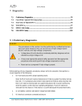
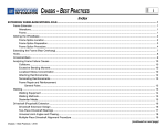
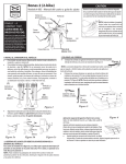
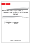
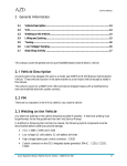
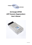
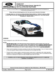
Service Manual
3 Vehicle Operation & Identification
3.1
Basic Theory of Operation ..........................................................................................18
3.2
Safety Features .............................................................................................................21
3.3
Modes of Operation .....................................................................................................21
3.4
Operating Strategies ....................................................................................................22
3.5
Ignition/Starter Switch ................................................................................................31
3.6
Standard Hybrid Indicators .......................................................................................32
3.7
Optional Hybrid Switches ...........................................................................................33
3.8
Automatic Transmission Operation ...........................................................................34
3.9
Speed Limits for Specific Vehicle Configurations ....................................................35
3.10
Hybrid Identification ...............................................................................................35
3.1 Basic Theory of Operation
The Balance Hybrid is a parallel hybrid vehicle. A parallel hybrid can use one or more motive
sources in combination for vehicle acceleration. The Balance hybrid has a gasoline engine along
with a large electric motor to provide propulsion force. A second smaller motor (Integrated
Starter/Generator – ISG) is attached to the engine’s FEAD system, its purpose is to serve as an
engine starter and to charge the high voltage system. An energy storage system, a battery,
provides electrical energy storage.
The primary energy saving mechanisms used by the hybrid are engine idle-off strategy and
regenerative braking. At low speeds, when the engine is not required for drive demand or ESS
charging, the engine will be shutdown. When required the engine will be re-started quickly,
usually by the FEAD ISG. When the engine is shutdown the DC/DC converter and electric
power assist system will be enabled to provide the 12 volt charge and power steering and brakes.
When the engine is running, these functions are provided by the FEAD power assist pump and
alternator.
Azure Dynamics Balance Hybrid-electric Vehicle – 2008 Ford E-450
18
Service Manual
FEAD
Starter / Generator
Engine
Starter /
Generator
Inverter
Energy Storage System
MPT Motor
Inverter
MPT Motor /
Generator
Transmission
Vehicle Control
Unit (VCU)
DC/DC
Converter
Power Assist
System (Motor,
Inverter & Pump)
Balance Hybrid System Schematic
In typical hybrid mode operation, the vehicle will accelerate at low speeds with the engine off
(electric only mode). The engine will be started by the ISG and the MPT will continue to assist
the engine until it is up to speed. At that point the engine will provide most of the propulsion
power, except during transient acceleration conditions, where the MPT will assist. In the case of
low SOC, the ISG will charge the ESS by absorbing power from the engine. During braking, the
MPT motor will act as a generator, slowing the rear wheels and charging the battery pack, the
vehicle brake lamps will be illuminated during regenerative braking events if the requested
regenerative braking torque exceeds 150Nm. At lower speeds the engine will shut down again.
The graph below illustrates typical hybrid operation during a drive cycle.
Azure Dynamics Balance Hybrid-electric Vehicle – 2008 Ford E-450
19
Service Manual
Typical Hybrid System Operation
Azure Dynamics Balance Hybrid-electric Vehicle – 2008 Ford E-450
20
Service Manual
3.2 Safety Features
The following list indicates some of the safeguards incorporated in the design of the hybrid
vehicle to disconnect the high voltage and to ensure that the vehicle is kept safe at all times.
1. The high voltage system is disconnected when the vehicle’s ignition key is turned to the OFF
position.
2. There are 2 inertia switches on the hybrid vehicle that may be activated in the case of an
accident:
• The Inertia Fuel Shut-off (IFS) switch – Ford standard equipment that automatically
disables the engine’s fuel pump.
• The hybrid-electric shut-off inertia switch – Automatically disables the high voltage
electrical system.
3. Whenever the high voltage service disconnect pin is removed, the high voltage system will
be disabled. It is located at the front end of the battery pack.
4. The battery pack contains a fuse that will open in the event of a short circuit.
5. If the vehicle’s ignition key is on, and the high voltage battery temperature exceeds 75°C
(167°F), the thermal sensors will disconnect the high voltage battery.
6. The VCU and ESS continually monitor the potential resistance between the high voltage
system and the chassis. If the resistance falls below an acceptable threshold the VCU / ESS
will open the contactors in the ESS and the vehicle will be forced into a “Conventional
Mode” .The “HYBRID SERVICE” lamp will be illuminated.
7. Vehicle Brake Lamp Operation During Regenerative Braking EventsThe vehicle brake lamps will be illuminated during regenerative braking events if the
requested regenerative braking torque exceeds 150Nm.
3.3 Modes of Operation
Operation Modes
There are several different modes that the vehicle will operate in depending on driver /
technician request or fault conditions being present. The table below details these modes.
Mode
Hybrid
EV
Conventional
Description
Normal hybrid functionality.
Electric only mode. Vehicle will operate in EV mode in low power/speed
conditions. It is also driver selectable in vehicles which include the optional
EV MODE switch.
Hybrid functionality disabled for service purposes, vehicle drives as a regular
conventional vehicle. This is selectable by the technician by removing the
conventional mode connector( C163) located under the Dash.
Note that this mode is not a true conventional mode. The vehicle will
operate in a manner similar to a conventional vehicle (no engine- off
operation, high voltage will not be enabled, etc) but the VCU still controls
much of the functionality of the vehicle. This mode should only be used for
certain diagnostic procedures. Leaving the vehicle in this mode will have
Azure Dynamics Balance Hybrid-electric Vehicle – 2008 Ford E-450
21
Service Manual
Forced
Conventional
Diagnostics
Conventional
Limp-Home
Forced EV mode
negative effects on the fuel economy and performance of the vehicle. The
connector should always be reconnected at the end of the diagnostic
procedure.
Due to a hybrid fault, the vehicle is forced to operate in conventional mode.
The vehicle will remain in conventional mode until key-off. At the next keyon event, the VCU will re-evaluate the fault conditions to determine if
conventional mode is still required.
Diagnostics mode is selectable through the diagnostics tool. It allows for
control of various VCU outputs and vehicle functions for purposes of vehicle
commissioning and diagnostics.
Due to a severe fault where the communication between the VCU and the
PCM has been jeopardized or the PCM feedback is flagging critical errors,
the vehicle will enter conventional limp-home mode. This is the same as
conventional mode, except the VCU will request zero torque in this
condition, and the engine will operate in idle mode.
In the case that vehicle cannot start the engine, the vehicle will drive in EV
mode. As the ESS SOC reduces, the drive power available will also reduce.
The power assist will remain available until the ESS is forced to open
contactors. The HYBRID SERVICE will be blinking (see section 3.5)
3.4 Operating Strategies
3.4.1 Arctic Mode Strategy
Cold EPAS Inverter
Application of EPAS 12V ignition power (J6-1) via the Arctic Mode relay (VCU C310S-H1) at
temperatures below -20°C can result in damage to the EPAS inverter, therefore at cold ambient
temperatures, the Arctic Mode relay must be deactivated to disable the EPAS inverter and the
engine must be forced on to provide power assist. The Arctic mode strategy works as follows:
1. At key off, the VCU power is latched for the time it would take the EPAS inverter to cool
from its current temperature to -15°C. This allows the VCU to make immediate
decisions based on EPAS inverter temperature if the ignition key is turned back on during
the power latch time period without having to enable the engine to assess ambient air
temperature. The time that the VCU power is latched is based on EPAS inverter
temperature as outlined in the table below:
EPAS
Inverter
Temperature
(°C)
-5
-4
0
VCU Power Latch
Time (s)
5
600
600
Azure Dynamics Balance Hybrid-electric Vehicle – 2008 Ford E-450
22
Service Manual
19
20
600
1200
The VCU power latch time is scaled linearly between the breakpoints and held constant
at the endpoint value for EPAS inverter temperature values outside the breakpoint range.
2. If directly before key-on the VCU is NOT alive, the EPAS inverter is disabled via the
Arctic Mode relay and the engine is forced on. Once the engine has been on for 30s, the
PCM-reported IAT is evaluated to determine the ambient temperature. If the PCMreported IAT temperature is above -10°C and the TM inverter temperature is above 10°C, the Arctic Mode relay is enabled, permitting EPAS operation, and the engine is
allowed to turn off. Otherwise, the EPAS inverter remains disabled and the engine
remains on. Once the EPAS inverter is enabled, if the reported inverter temperature falls
below -15°C , the EPAS inverter is disabled via the Arctic Mode Relay and the engine is
forced on again.
3. If directly before key-on the VCU is alive, if the EPAS inverter was previously warm
enough to be enabled and to allow the engine to turn off, the Arctic Mode relay is
immediately re-enabled to allow EPAS operation and the engine can remain off.
Otherwise, the Arctic Mode relay is disabled and the engine is forced on until the inverter
temperature increases as described in point 1.
Cold TM Inverter
The TM Inverter is not able to operate at ambient temperatures below -20C, requiring the vehicle
to be forced into conventional mode. The cold TM inverter strategy works as follows:
1. If directly before key-on the VCU is NOT alive, the TM inverter is disabled via the EMPS-Enable relay (VCU C308S-H3) and the vehicle is forced into conventional mode.
If the TM inverter temperature is above -10°C, the E-MPS-Enable relay is enabled to
permit TM inverter operation and the vehicle transitions into hybrid mode. Otherwise,
the TM inverter remains disabled and the vehicle remains in conventional mode.
Once the TM inverter is enabled and the vehicle transitions to hybrid mode, if the
reported inverter temperature falls below -15°C, the TM inverter is disabled and the
vehicle is forced into conventional mode again.
2. If directly before key-on the VCU is alive, if the TM inverter was previously warm
enough to be enabled and the vehicle was in hybrid mode, the TM inverter is immediately
enabled and the vehicle starts in hybrid mode. Otherwise, the TM inverter is disabled
and the vehicle starts in conventional mode until the inverter temperature increases as
described in point 1.
Azure Dynamics Balance Hybrid-electric Vehicle – 2008 Ford E-450
23
Service Manual
3.4.2 Engine Start-Up Strategy
Use of the 12V Starter Motor
The engine will be cranked with the ISG unless any one or more of the conditions listed below
are active.
12V Starter Source
Conventional Mode
ISG Inhibit
Condition
The vehicle is in Conventional mode
1. An ISG-related diagnostic trouble code has been flagged
by the VCU OR
2. The ISG is not ready for operation (slow boot-up on key
start)
Low ECT
ECT < 10°C
ESS Power Limit
ESS discharge power limit < 9500kW
ISG Torque Limit
ISG available torque limit < 80Nm
**NOTE: The 12V starter source is displayed on the Balance Diagnostic Tool.
Cranking Sequence
NO
Apply cranking
torque with ISG
YES
YES
Engine
speed >
125rpm?
NO
1st ISG
crank
attempt?
NO
Hybrid
Generate
Performance
DTC flagged
(P0A92)
12V starter
used first in
current crank
attempt
YES
Vehicle forced into EV
mode
NO
YES
Engage 12V
starter motor
YES
YES
First ISG
crank
attempt?
NO
Engine
fired?
Engine
speed >
125rpm?
NO
1st or 2nd
12V starter
crank
attempt?
NO
Starter
Performance
DTC flagged
(P1A31)
ISG used first
in current
crank attempt
NO
YES
Engine Failed
to Start DTC
flagged
(P0A0F)
Vehicle forced into EV
mode
YES
Successful ISG crank
1st or 2nd 12V
starter crank
attempt?
NO
Engine fired?
NO
YES
Engine Failed
to Start DTC
flagged
(P0A0F)
Successful 12V starter
crank
YES
Vehicle forced into EV
mode
Vehicle forced into EV
mode
Notes:
1. The sequence will begin at either of the yellow rectangles above. The start sequence
begins at “Engage 12V Starter Motor” if any of the conditions mentioned in the Use of
Azure Dynamics Balance Hybrid-electric Vehicle – 2008 Ford E-450
24
Service Manual
12V Starter section above are satisfied. Otherwise, the sequence begins at “Apply
cranking torque with ISG”.
2. Maximum ISG engagement time = 4s
3. Maximum 12V starter engagement time based on ECT as outlined in the table below:
ECT (°C)
Maximum 12V
Starter
Engagement Time
(s)
-40
10
-18
4.5
0
2.5
20
2
50
2
The maximum 12V starter engagement time is scaled linearly between the breakpoints and held
constant at the endpoint value for ECT values outside the breakpoint range.
3.4.3 Coolant Pump Strategy
When the hybrid powertrain is enabled, the coolant pump is enabled. If the ESS coolant
temperature drops below 12°C (>=14°C to reset condition) AND the ESS maximum module
temperature drops below 18°C (>=20°C to reset condition), then the coolant pump is cycled (10s
ON; 20s OFF) to allow the ESS to heat up faster.
ESS Cooling After Key Off
When HV is disabled, either for a key off event or for a transition into conventional mode, if the
ESS coolant temperature is greater than 30°C and the ESS maximum module temperature is
greater than 35°C, then the coolant pump will be enabled for 2 minutes after HV is disabled.
Engine Derating for Overheating
Maximum available engine torque is derated based on ECT as outlined in the table below:
ECT (°C)
Maximum Engine
Torque (Nm)
105
510
110
270
118
145
122
90
The maximum engine torque is scaled linearly between the breakpoints and held constant at the
endpoint value for ECT values outside the breakpoint range.
Azure Dynamics Balance Hybrid-electric Vehicle – 2008 Ford E-450
25
Service Manual
3.4.4 Radiator Fan Strategy
Triple Radiator Fans (MY09 and MY08 Production Level Vehicles)
All three radiator fans shall be enabled if cab a/c is enabled. The component temperature
thresholds for enabling the radiator fans are outlined in the table below:
Component
1 Fan Temperature
2 Fan Temperature
3 Fan Temperature
Threshold (°C)
Threshold (°C)
Threshold (°C)
ESS (coolant
With Engine ON
With Engine ON
With Engine ON
temp)
> 25 (reset <= 20)
n/a
> 35 (reset <= 30)
With Engine OFF
With Engine OFF
With Engine OFF
> 35 (reset <= 30)
n/a
> 45 (reset <= 40)
Engine (coolant
> 90 (reset <= 85)
> 98 (reset <= 93)
> 103 (reset <= 98)
temp)
**NOTES:
1. In hybrid mode, the radiator fans will only be enabled if the hybrid powertrain is enabled.
Additionally, the engine coolant temperature conditions will only be used to enable the
radiator fans if the engine is enabled.
2. In conventional mode, the radiator fans will only be enabled if the engine is enabled and
the engine coolant temperature conditions are met. The radiator fans will not be enabled
for ESS coolant temperature conditions.
3. The VCU does not disable the radiator fans at high vehicle speeds
4. Additionally, if the 12V battery management state is in Critical Load Shed (see 12V
Battery Management Strategy), only the single radiator fan shall be allowed to be enabled
should the conditions described above be met. The dual radiator fans shall be disabled.
Single PWM Radiator Fan (MY08 Pre-Production Level Vehicles)
The radiator duty cycle (DC) shall be set to 100% if the cab a/c is enabled. The component
temperature thresholds controlling the radiator fan DC are outlined in the table below, with the
DC being scaled linearly between the 0% and 100% component temperatures:
Component
0% DC Temperature
100% DC
Threshold (°C)
Temperature
Threshold (°C)
ESS (coolant
With Engine ON
With Engine ON
temp)
30
35
With Engine OFF
With Engine OFF
35
40
Engine (coolant
95
103
temp)
**NOTES:
1. In hybrid mode, the radiator fan DC will only be greater than 0% if the hybrid powertrain
is enabled. Additionally, the engine coolant temperature conditions will only be used to
command a radiator fan DC greater than 0% if the engine is enabled.
Azure Dynamics Balance Hybrid-electric Vehicle – 2008 Ford E-450
26
Service Manual
2. In conventional mode, the radiator fan DC will only be greater than 0% if the engine is
enabled and the engine coolant temperature conditions are met. The radiator fan DC will
not be controlled by ESS coolant temperature conditions.
3. The VCU does not disable the radiator fans at high vehicle speeds
4. Additionally, if the 12V battery management state is in Critical Load Shed (see 12V
Battery Management Strategy), radiator fan DC shall be derated to a maximum of 50%.
3.4.5 IDS Tool Connection
In order to perform engine diagnostics, the IDS tool can be connected to the PCM at any time.
3.4.6 Body A/C Strategy
On vehicles equipped with body A/C, the body A/C shall be enabled if all of the following
conditions are met:
1. Body A/C clutch is engaged
2. HV is enabled
3. 12V battery voltage state is NOT Load Shed or Critical Load Shed (see 12V Battery
Management Strategy)
4. ISG is not faulty
5. SOC >= 41%
The speed setpoint of the body A/C is based on the SOC as outlined in the table below:
ESS SOC
Body A/C Speed
(%)
Setpoint (rpm)
39
1600
43
3000
75
3000
80
5000
The body A/C speed setpoint is scaled linearly between the breakpoints and held constant at the
endpoint value for SOC values outside the breakpoint range.
3.4.7 TM Power Derating based on SOC
The maximum TM motor acceleration power limit is derated based on SOC as outlined in the
table below. The ESS SOC should only reach such critically low levels when the vehicle is in
Forced EV mode. Once 20% has been reached (or the vehicle has been in Forced EV mode for 5
minutes), traction power will be disabled, however HV and EPAS will remain enabled.
ESS SOC
Maximum TM
(%)
Acceleration
Azure Dynamics Balance Hybrid-electric Vehicle – 2008 Ford E-450
27
Service Manual
Power Limit (kW)
0
60
80
20
30
35
The maximum acceleration power limit is scaled linearly between the breakpoints and held
constant at the endpoint value for SOC values outside the breakpoint range.
3.4.8 12V Battery Management Strategy
12V Battery Management
Strategy
T1:
[V < 12.4 debounced for 30 s OR
V < 12.0 debounced for 8 s OR
V < 11.5 debounced for 5 s]
AND
[Powertrain state is enabled]
Normal
No engine on request
T1
Engine On
T3
T2:
V < 12.4 debounced for 7 s during current state
Request engine on
No high idle request
T2
T4
T3:
40 s during current state AND T2 not true
High Idle
Request engine on
Request high idle
No charge lamp request
Body AC system request passed through
T5 AND Hybrid Mode
T5 AND Conventional Mode
T6 AND Conventional Mode
T6
T4:
40 s during current state AND T5 not true
Load Shed
Request engine on
Request high idle
Enable charge lamp
Disable body AC system (lv and hv)
Rad fans request passed through
VCU flags fault (latched for the cycle)
T5
Critical Load Shed
T6 AND Hybrid Mode
Request engine on
Request high idle
Enable charge lamp
Body AC disabled (lv and hv)
Rad fans request modified:
Triple fan setup: (3 fansàsingle fan)
PWM setup: (90%à50% duty cycle)
T5:
V < 12.4 debounced for 15 s during current state
T6:
V > 12.4 debounced for 30 s during current state
Notes:
- ‘V’ refers to 12 volt battery voltage read at vehicle ignition
- In conventional mode, the “Engine On” state is bypassed in both directions
because the engine is already on.
- Also in conventional mode, the step “Load Shed” is skipped in both directions as
body AC system is disabled in conventional mode anyways and hence this state
becomes identical to the “High Idle” state.
3.4.9 Engine High Idle Strategy
High idle will be requested of the engine for the 12V battery management (see 12V Battery
Management Strategy). It will also be requested for low SOC based on the following conditions:
1. With body a/c enabled
a. If the vehicle is in P, N, R or D with vehicle speed < 5km/h, high idle will be
requested if the SOC < 44% (reset when SOC >= 47%)
Azure Dynamics Balance Hybrid-electric Vehicle – 2008 Ford E-450
28
Service Manual
b. If the vehicle is in D with vehicle speed >= 5km/h, high idle will be requested if
the SOC < 49% (reset when SOC >= 51%)
2. Without body a/c enabled
a. If the vehicle is in P, N, R or D with vehicle speed < 5km/h, high idle will be
requested if the SOC < 39% (reset when SOC >= 45%)
b. If the vehicle is in D with vehicle speed >= 5km/h, high idle will be requested if
the SOC < 45% (reset when SOC >= 51%)
3.4.10 Cab A/C Strategy
In vehicles equipped with cab a/c, the maximum engine-off time is modified to ensure cab
temperature is maintained. The engagement of the cab a/c system is detected by the VCU by 2
different methods, depending on the vehicle:
1. MY08 cut-aways and stripped chassis - the cab a/c clutch state is sent to the VCU from
the PCM over CAN
2. MY08 shuttle buses and MY09 vehicles - a cab a/c pressure switch digital input to the
VCU indicates the engagement of the cab a/c system
The intake air temperature reported by the PCM over CAN is used by the VCU as the ambient
air temperature. However, this temperature is only considered valid for the a/c strategy after the
engine has been on for 20s, to ensure air flow through the intake. If the cab a/c is engaged and
the ambient air temperature is greater than or equal to 50°C, the engine is kept on until the
ambient air temperature falls below 48°C or the cab a/c is no longer engaged. If the cab a/c is
engaged and the ambient air temperature is less than 50°C, the maximum time that the engine is
allowed to be off is based on the ambient air temperature outlined in the table below:
Ambient Air
Temperature
(°C)
20
25
30
35
40
45
50
Maximum Engine
Off Time (s)
900
240
180
90
60
30
0
The maximum engine off time is scaled linearly between the breakpoints and held constant at the
endpoint value for ambient air temperature values outside the breakpoint range. When the
engine is turned on because the maximum off-time has been exceeded, it remains on for a
minimum of 30s for the cab a/c strategy, before it is allowed to turn off again.
Over key cycles, the last known ambient air temperature and cab a/c state are saved by the VCU,
to avoid having to wait for 20s of engine on time on the next key cycle before the ambient air
Azure Dynamics Balance Hybrid-electric Vehicle – 2008 Ford E-450
29
Service Manual
temperature can be evaluated. At key on, if the previous ambient air temperature was greater
than 35°C and the cab a/c was engaged, the engine will be immediately forced on at key start.
Behavior difference between vehicles with cab a/c pressure switch and vehicles with cab a/c
clutch state sent over CAN
In situations where the VCU is not alive before the key is turned on, there is a slight difference in
response to a cab a/c request by the driver (via dash switch) prior to key-on between vehicles that
have a cab a/c pressure switch and those that have the cab a/c clutch state reported over CAN.
• Cab a/c pressure switch: When the key is turned on, the cab a/c request is recognized by
the VCU and the engine is forced on after it has been off for the maximum off time listed
above.
• Cab a/c clutch state reported over CAN: When the key is turned on, the cab a/c request
will NOT be recognized by the VCU initially; hence the engine will remain off regardless
of the driver’s a/c request until the engine has been enabled for some other reason.
3.4.11 Cab Heater Strategy
The maximum engine-off time is modified to ensure cab heat is maintained in cold ambient
temperatures. Similar to the cab A/C strategy, the intake air temperature reported by the PCM
over CAN is used by the VCU as the ambient air temperature. However, this temperature is only
considered valid for the cab heater strategy after the engine has been on for 20s, to ensure air
flow through the intake. If the ambient air temperature is less than or equal to -30°C, the engine
is kept on until the ambient air temperature rises above -28°C. If the ambient air temperature is
greater than -30°C, the maximum time that the engine is allowed to be off is based on the
ambient air temperature outlined in the table below:
Ambient Air
Temperature
(°C)
-30
-20
-10
0
10
Maximum Engine
Off Time (s)
0
30
240
300
900
The maximum engine off time is scaled linearly between the breakpoints and held constant at the
endpoint value for ambient air temperature values outside the breakpoint range. When the
engine is turned on because the maximum off-time has been exceeded, it remains on for a
minimum of 30s for the cab heater strategy, before it is allowed to turn off again.
Note that the engine is also turned on based on engine coolant temperature and ambient air
temperature for the engine warm-up strategy, as listed in the Engine Start Source and Engine On
Source sections.
Azure Dynamics Balance Hybrid-electric Vehicle – 2008 Ford E-450
30
Service Manual
3.5 Ignition/Starter Switch
The ignition/starter switch functions in the same manner as in a non-hybrid Ford E-450 except
for the starting operation described below. Refer to the Ford E-450 Owner’s Guide for more
information.
3.5.1 Starting the Vehicle
1. Ensure the gearshift is in P (Park)
2. Turn the key to “4” (ON) without turning the key to “5” (START). All electrical circuits
will be operational, warning lights will be illuminated.
Figure 4: Ignition/starter switch position
Turn the key to “5” (START) momentarily and hold for about 1 second and release. The Green
“HYBRID ENABLED” light on the dash will illuminate which indicates that the vehicle is ready
to drive, even if the engine is not running.
Whenever the Green “HYBRID ENABLED” light is illuminated, the vehicle is “ON” and ready
to drive, even if the engine is not running.
WARNING
When the key is in the ON position (“HYBRID ENABLED” light is ON), the
engine may start or stop without warning. Remove the key from the ignition
when working on the vehicle or under the hood. The vehicle should not be left
unattended with the key in the RUN position.
3.5.2 How to Turn the Hybrid OFF
1. Come to a complete stop.
Azure Dynamics Balance Hybrid-electric Vehicle – 2008 Ford E-450
31
Service Manual
2. Engage the parking brake.
3. Place the gear selector in P (Park)
4. Turn the key to the OFF position.
3.6 Standard Hybrid Indicators
There are two lights on the driver’s console, located to the right of the steering column, a Green
“HYBRID ENABLED” light and a Yellow “HYBRID SERVICE” light, (refer to illustration).
The function of these lights is described in the table that follows.
Figure 5: Hybrid Indicators
Figure 6: Hybrid Controls and Indicators
Azure Dynamics Balance Hybrid-electric Vehicle – 2008 Ford E-450
32
Service Manual
3.6.1
HYBRID ENABLED
The green light emitting diode (LED) lights when the vehicle is ready to drive. If the technician
has commanded Conventional Mode by removing the jumper connector (C163S) which is
located under the dash, the light will remain OFF while the vehicle is running.
3.6.2
HYBRID SERVICE
If any problem is detected in the hybrid system, the yellow LED will light or flash depending on
the type of fault. If the HYBRID SERVICE light is ON or was ON during a drive cycle the
vehicle should be taken to the garage for service.
3.6.3
Limp Home Mode
Certain failures of vehicle systems (both conventional and hybrid) will not allow the vehicle to
operate as normal. The vehicle will have reduced performance levels. This limited operation
allows the driver to pull over safely to the side of the road and call for service. The vehicle
should not be run for extended periods of time in Limp Home Mode.
3.7 Optional Hybrid Switches
Depending on the application, the RBS OFF (optional) switch may be present on the vehicle.
3.7.1 RBS OFF (Optional on Shuttle Bus Only)
When this switch is pressed, the Regenerative Braking System (RBS) will be turned off and the
LED in the switch will illuminate. To re-enable regenerative braking, press the switch again and
the light will shut off.
Note : Whenever the vehicle is re-started, the default mode is to always have RBS on.
Azure Dynamics Balance Hybrid-electric Vehicle – 2008 Ford E-450
33
Service Manual
3.7.2 Electric Vehicle (optional)
When this switch is pressed, the light will illuminate and the vehicle will switch from hybrid
mode into electric only mode (no engine start) at a reduced acceleration rate and reduced
maximum vehicle speed. To re-enable hybrid mode, press the EV switch again and the light will
shut off. While in electric-only mode, if the ESS is sufficiently discharged, the engine will be
forced back on to charge the ESS. Whenever the vehicle is re-started, the default mode is
Hybrid.
3.8 Automatic Transmission Operation
The brake-shift interlock and gear selection functions are the same as on a non-hybrid Ford E450. Refer to the Ford E-450 Owner’s Guide for more information.
WARNING
When leaving the vehicle…
Always set the parking brake fully and make sure the gearshift is latched in P
(Park). Turn the ignition to the LOCK position and remove the key whenever
you leave your vehicle.
3.8.1 Vehicle Creep
As in a non-hybrid, the hybrid vehicle is designed to “creep” forward when in gear if the brake
pedal is released and the throttle pedal is not pressed.
Azure Dynamics Balance Hybrid-electric Vehicle – 2008 Ford E-450
34
Service Manual
3.9 Speed Limits for Specific Vehicle Configurations
For step vans and cut-a-ways, the vehicle speed limit is 65mph (105km/h). For shuttle buses, the
vehicle speed limit is 70mph (112 km/h).
3.10 Hybrid Identification
The vehicle can be identified as a hybrid by the following features:
•
•
•
•
The presence of hybrid components installed on the vehicle. Hybrid Warning Labels
under the hood.
Orange colored cables and looming that are used for high voltage. They are visible
under the vehicle
“HYBRID ENABLED” and “HYBRID SERVICE” indicator lights on the dash.
Customer specific Hybrid labeling on the vehicle Note- these labels may or may not
be present, these are customer controlled.
3.10.1 High Voltage Cables
WARNING
•
High voltage cables are identified by highly visible orange looming or orange
stripes.
•
The presence of orange high voltage cables under the hood and under the
vehicle identifies the vehicle as a hybrid.
Azure Dynamics Balance Hybrid-electric Vehicle – 2008 Ford E-450
35