1
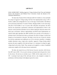
MAZDA SKYACTIV-D Engine (EURO 6)
Common Rail System (CRS) Service
Manual
Issued : April 2012
Applicable Vehicle :
Vehicle Name
Release Date
CX-5
March 2012
50000061E
© 2012 by DENSO CORPORATION
All rights reserved. This material may not be reproduced
or copied, in whole or in part, without the written
permission of DENSO Corporation.
Table of Contents
Operation Section
1. Introduction
1.1
SKYACTIV . . . . . . . . . . . . . . . . . . . . . . . . . . . . . . . . . . . . . . . . . . . . . . . . . . . . . . . . . . . . . . . . . . . . . . . . . . . . . 2-1
1.2
SKYACTIV-D Features . . . . . . . . . . . . . . . . . . . . . . . . . . . . . . . . . . . . . . . . . . . . . . . . . . . . . . . . . . . . . . . . . . . 2-1
2. Applicable Vehicles and Parts Information
2.1
Outline . . . . . . . . . . . . . . . . . . . . . . . . . . . . . . . . . . . . . . . . . . . . . . . . . . . . . . . . . . . . . . . . . . . . . . . . . . . . . . . . 2-2
2.2
Applicable Vehicles . . . . . . . . . . . . . . . . . . . . . . . . . . . . . . . . . . . . . . . . . . . . . . . . . . . . . . . . . . . . . . . . . . . . . . 2-3
2.3
List of Primary Parts . . . . . . . . . . . . . . . . . . . . . . . . . . . . . . . . . . . . . . . . . . . . . . . . . . . . . . . . . . . . . . . . . . . . . 2-3
2.4
System Configuration . . . . . . . . . . . . . . . . . . . . . . . . . . . . . . . . . . . . . . . . . . . . . . . . . . . . . . . . . . . . . . . . . . . . 2-5
3. Supply Pump
3.1
Outline . . . . . . . . . . . . . . . . . . . . . . . . . . . . . . . . . . . . . . . . . . . . . . . . . . . . . . . . . . . . . . . . . . . . . . . . . . . . . . . . 2-8
3.2
Suction Control Valve (SCV) . . . . . . . . . . . . . . . . . . . . . . . . . . . . . . . . . . . . . . . . . . . . . . . . . . . . . . . . . . . . . . . 2-9
4. Rail
4.1
Outline . . . . . . . . . . . . . . . . . . . . . . . . . . . . . . . . . . . . . . . . . . . . . . . . . . . . . . . . . . . . . . . . . . . . . . . . . . . . . . . 2-10
5. Injectors
5.1
Outline . . . . . . . . . . . . . . . . . . . . . . . . . . . . . . . . . . . . . . . . . . . . . . . . . . . . . . . . . . . . . . . . . . . . . . . . . . . . . . . 2-11
5.2
Operation. . . . . . . . . . . . . . . . . . . . . . . . . . . . . . . . . . . . . . . . . . . . . . . . . . . . . . . . . . . . . . . . . . . . . . . . . . . . . 2-12
5.3
Injector Return Back Pressure System . . . . . . . . . . . . . . . . . . . . . . . . . . . . . . . . . . . . . . . . . . . . . . . . . . . . . . 2-13
6. Control System Parts
6.1
Engine ECU. . . . . . . . . . . . . . . . . . . . . . . . . . . . . . . . . . . . . . . . . . . . . . . . . . . . . . . . . . . . . . . . . . . . . . . . . . . 2-15
6.2
Sensors . . . . . . . . . . . . . . . . . . . . . . . . . . . . . . . . . . . . . . . . . . . . . . . . . . . . . . . . . . . . . . . . . . . . . . . . . . . . . . 2-15
7. Fuel Injection Control
7.1
Injection Pattern. . . . . . . . . . . . . . . . . . . . . . . . . . . . . . . . . . . . . . . . . . . . . . . . . . . . . . . . . . . . . . . . . . . . . . . . 2-19
7.2
Microinjection Quantity Correction Control . . . . . . . . . . . . . . . . . . . . . . . . . . . . . . . . . . . . . . . . . . . . . . . . . . . 2-20
7.3
Injector Temperature Characteristic Correction Control . . . . . . . . . . . . . . . . . . . . . . . . . . . . . . . . . . . . . . . . . 2-23
7.4
Interval Dependence Correction . . . . . . . . . . . . . . . . . . . . . . . . . . . . . . . . . . . . . . . . . . . . . . . . . . . . . . . . . . . 2-25
7.5
Exhaust Gas Recirculation (EGR) Control . . . . . . . . . . . . . . . . . . . . . . . . . . . . . . . . . . . . . . . . . . . . . . . . . . . 2-26
7.6
i-stop Control . . . . . . . . . . . . . . . . . . . . . . . . . . . . . . . . . . . . . . . . . . . . . . . . . . . . . . . . . . . . . . . . . . . . . . . . . . 2-27
8. Other Controls
8.1
Jet Pump (4WD Only) . . . . . . . . . . . . . . . . . . . . . . . . . . . . . . . . . . . . . . . . . . . . . . . . . . . . . . . . . . . . . . . . . . . 2-29
9. Exhaust Gas Treatment System
9.1
Diesel Particulate Filter (DPF) System . . . . . . . . . . . . . . . . . . . . . . . . . . . . . . . . . . . . . . . . . . . . . . . . . . . . . . 2-30
10. Diagnostic Trouble Codes (DTC)
10.1
DTC List. . . . . . . . . . . . . . . . . . . . . . . . . . . . . . . . . . . . . . . . . . . . . . . . . . . . . . . . . . . . . . . . . . . . . . . . . . . . . . 2-32
11. Wiring Diagrams
11.1
Engine ECU External Wiring Diagrams . . . . . . . . . . . . . . . . . . . . . . . . . . . . . . . . . . . . . . . . . . . . . . . . . . . . . . 2-52
11.2
Connector Diagrams . . . . . . . . . . . . . . . . . . . . . . . . . . . . . . . . . . . . . . . . . . . . . . . . . . . . . . . . . . . . . . . . . . . . 2-58
Operation Section
2 1
1. Introduction
1.1 SKYACTIV
The name SKYACTIV was chosen for several innovative next generation MAZDA technologies to evoke an
image of vehicles that are not only "fun to drive", but achieve "superior environmental friendliness and safety." This manual introduces the following six key SKYACTIV technologies.
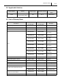
Technological Field
Engine
Name
SKYACTIV-G
Description
A next-generation, high efficiency Direct Fuel
Injection (DFI) engine that suppresses knocking
and achieves a high compression ratio (14:0).
SKYACTIV-D
A next-generation clean diesel engine that
achieves a low compression ratio (14:0).
Transmission
SKYACTIV-Drive
A next generation, high efficiency automatic
transmission that achieves a high torque transmission ratio via lockup in all regions.
SKYACTIV-MT
A next-generation manual transmission for FF
vehicles that is both lightweight and compact.
Body
SKYACTIV-Body
A next-generation, lightweight body that achieves
high rigidity combined with high collision safety.
Chassis
SKYACTIV-Chassis
A next-generation, high-performance, lightweight
chassis that creates an effective balance between
handling, and driving comfort.
1.2 SKYACTIV-D Features
SKYACTIV-D takes the following measures to lower fuel consumption.
Use of a variable valve lift mechanism to improve ignition stability when the engine is cold.
Use of two-stage supercharging control to generate high levels of supercharging efficiently. As such low
emissions performance, low fuel consumption performance, high torque, and high response are attained.
Use of Exhaust Gas Recirculation (EGR) to clean exhaust gas and improve fuel economy.
Use of i-stop to improve fuel economy, as well as to lower the amount of exhaust gas and idling noise.
Low Compression Ratio
Combustion performance is improved via a low compression ratio (14:0).
Weight Reductions
Aluminum alloy cylinder block
Integrated exhaust manifold and cylinder head
Weight Reductions and Reduced Mechanical Resistance Losses
Optimized piston shape
Lightweight crankshaft journals
2 2
Operation Section
2. Applicable Vehicles and Parts Information
2.1 Outline
The SKYACTIV-D engine is equipped with the MAZDA CX-5 released in March 2012.
As a result, a Common Rail System (CRS) for the SKYACTIV-D engine has been newly designated.
This manual describes items specific to the parts used in the CRS for the SKYACTIV-D engine. For CRS
basics, refer to the "COMMON RAIL SYSTEM SERVICE MANUAL -OPERATION (Doc ID: 00400534EA)."
The SKYACTIV-D engine CRS has undergone the following improvements to comply with exhaust gas regulations for 2014 (Euro 6).
System pressure: 200 MPa
Supply pump (HP3): Complies with pressures up to 200 MPa, newly designated injector return system
discharge port
Rail: Complies with pressures up to 200 MPa, use of pressure relief valve
Injectors: G3P (use of piezo injectors)
Use of DPF system
Use of injector return system
Operation Section
2 3
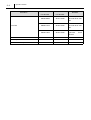
2.2 Applicable Vehicles
Vehicle Name
CX-5
Vehicle
LDA-KE2FW (2WD)
LDA-KE2AW (4WD)
Engine Type
Exhaust Volume
SH
2.2 L
Production Start
Date
March 2012
2.3 List of Primary Parts
DENSO
Customer
Part Number
Part Number
Supply Pump
294000-166#
SH01-13800
Rail
095600-502#
SH01-13GC0
Injector
295900-026#
SH01-13H50
275700-507#
SH02-18881
275700-511#
SH04-18881
275700-508#
SH01-18881
275700-506#
SH1A-18881
275700-509#
SH1B-18881
275700-504#
SH1J-18881
275700-502#
SH1K-18881
275700-510#
SH1M-18881
Crankshaft Position Sensor
949979-066#
PE01-18221
NE Sensor
Cylinder Recognition Sensor
949979-188#
N3R4-18221
G Sensor
Coolant Temperature Sensor
179700-048#
SH01-18840
Fuel Temperature Sensor
294009-010#
SH01-18822
A/F Sensor
211200-444#
SH01-188G1
265600-327#
SH01-187G0
Part Name
ECU
(Diesel Air Control Valve)
Exhaust Gas Recirculation (EGR) Valve
HP3
G3P
AT, 2WD
Low power
AT, 4WD
High power
MT, 2WD
Low power
MT, 4WD
Low power
AT, 4WD
Low power
MT, 4WD
High power
AT, 4WD
High power
AT, 2WD
High power
With O-ring
Oxidation
catalyst
inlet
Exhaust Gas Temperature Sensor
ETB
Remarks
265600-328#
SH02-187G0
197920-010#
SH01-136B0
150100-020#
SH01-20300
DPF catalyst inlet
2 4
Operation Section
Part Name
DENSO
Customer
Part Number
Part Number
Remarks
With heater,
186300-898#
SH01-13480
left-hand driver vehicles
Without heater,
Fuel Filter
186000-707#
SH02-13480
left-hand driver vehicles
Without heater,
186300-706#
SH03-13480
right-hand
vehicles
Intercooler
127100-411#
SH01-13565
Jet Pump
167750-106#
-
Electric Water Pump
113730-059#
KD-612FX
4WD
For the EU
driver
Operation Section
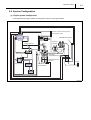
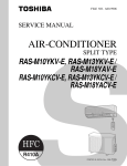
2.4 System Configuration
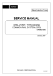
(1) Engine System Configuration
The SKYACTIV-D engine system is configured as shown in the figure below.
2 5
2 6
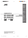
Operation Section
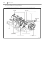
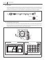
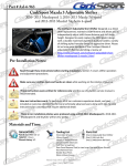
(2) Mounting Figure for Primary CRS Parts
The primary parts for the SKYACTIV-D CRS are mounted as shown in the figure below.
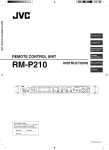
Operation Section
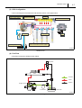
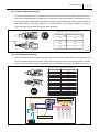
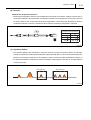
(3) CRS Configuration
The functional parts of the SKYACTIV-D CRS are shown in the figure below.
SKYACTIV-D
(4) Fuel Flow
Fuel flows through the CRS as shown below.
Conventional Type
2 7
2 8
Operation Section
3. Supply Pump
3.1 Outline
The supply pump used with the SKYACTIV-D engine CRS (HP3) complies with pressures up to 200 MPa.
In addition, a port has been established to feed fuel to the injector return system used with the CRS.
The fuel temperature sensor is separate from the pump, and is now set in the path between the supply pump
and the fuel return.
Operation Section
2 9
3.2 Suction Control Valve (SCV)
The SCV used with the SKYACTIV-D engine CRS is a normally open SV3 type. The SV3 type has the following features.
A more compact design compared to the SV1 type due to a smaller solenoid
Improved valve sliding performance
Operation Concept Diagram
2 10
Operation Section
4. Rail
4.1 Outline
The rail used with the SKYACTIV-D engine CRS is compliant with pressures up to 200 MPa. The rail uses
a new model pressure relief valve.
(1) Pressure Relief Valve
The pressure relief valve controls rail fuel pressure. If rail pressure reaches or exceeds a specified value,
a solenoid coil is energized to open a path in the valve and return fuel to the fuel tank, thereby reducing
pressure to the specified value.
(2) Rail Pressure Sensor
The rail pressure sensor is compliant with pressures up to 200 MPa.
Operation Section
2 11
5. Injectors
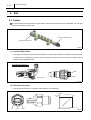
5.1 Outline
The G3P type piezo injectors equipped with the SKYACTIV-D engine CRS can inject fuel at extremely high
pressure (200 MPa). As a result, the atomization of the fuel mist from the nozzle is improved, leading to
increased combustion efficiency, and reduced exhaust gas quantity.
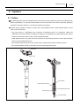
A piezo injector primarily consists of a piezo stack, large diameter piston, small diameter piston, control
valve, and nozzle needle.
The piezo stack is a laminated body consisting of alternating layers of a substance called PZT
(PbZrTiO3), and thin electrodes. By applying voltage, the characteristics of a piezo element are used to
expand and shrink the stack via the inverse piezoelectric effect.
Small displacements of the piezo stack are expanded by transmitting actuation from the large diameter
piston to the small diameter piston.
The small diameter piston moves the control valve to regulate the pressure inside the injector.
The nozzle needle is moved up and down via control valve pressure control.
2 12
Operation Section
Correction Points Using QR Codes
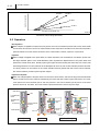
5.2 Operation
Non-Injection
When voltage is not applied to the piezo stack, the pressure in the control chamber and at the bottom of the nozzle needle
is at the same value as fuel in the rail. The nozzle needle remains closed due to the difference in surface area exposed to
pressure between the control chamber and bottom of the nozzle needle. Therefore, injection is not performed.
Injection
When voltage is applied to the piezo stack, the stack expands. The transmission of actuation power from
the large diameter piston to the small diameter piston expands the displacement of the piezo stack and
pushes the control valve down, thereby opening the upper seat and closing the lower seat. As a result, fuel
is discharged from the control chamber to the leak path via orifice A, and control chamber pressure decreases. Since pressure on the bottom of the nozzle needle becomes greater than that of the control chamber,
the nozzle needle is pushed up and injection begins.
Injection Complete
When the voltage applied to the piezo stack is removed, the stack shrinks, and both the large and small diameter
pistons, as well as the control valve rise. Additionally, the lower seat opens and the upper seat closes. As a result,
a fuel path to the control chamber opens, and fuel pressure in the control chamber quickly returns to the same
pressure as the rail. Therefore, the nozzle needle is pushed downward, and fuel injection stops.
Operation Section
2 13
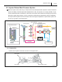
5.3 Injector Return Back Pressure System
When the injector return side is dry (no fuel) and air enters the displacement expansion chamber inside the
injector, the ability to transmit piezo stack displacement is lost, and injection is no longer possible. To prevent the aforementioned circumstances, fuel is sent to the injector return side from the supply pump via the
feed valve to apply back pressure. The air is therefore compressed and eliminated to improve startability.
The injector return system is built into the lower case of the engine compartment. Injector return system construction and operation are detailed below.
(1) Construction
Injector return system construction is shown in the figure below.
2 14
Operation Section
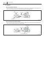
(2) Operation
When the Feed Valve Operates
When the pressure in the lower case drops below a constant value, a ball inside the valve presses on a
spring, and fuel flows into the lower case (injector side) from the supply pump.
When the Back Pressure Valve Operates
When the fuel returning from the injectors exceeds a constant value, a ball inside the valve presses on a
spring, and a fuel path is opened to the fuel tank side.
Operation Section
2 15
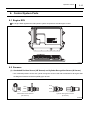
6. Control System Parts
6.1 Engine ECU
The engine ECU regulates the fuel injection system and performs overall engine control.
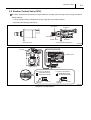
6.2 Sensors
(1) Crankshaft Position Sensor (NE Sensor) and Cylinder Recognition Sensor (G Sensor)
The crankshaft position sensor and cylinder recognition sensor used with the SKYACTIV-D engine CRS
are Magnetic Resistance Element (MRE) type devices.
2 16
Operation Section
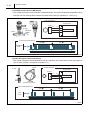
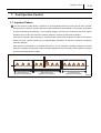
Crankshaft Position Sensor (NE Sensor)
The crankshaft position sensor detects the crankshaft angle. The pulsar has 56 teeth (separated at 6°CA
intervals, with four missing teeth to detect Top Dead Center [TDC] for cylinders no. 1 and no. 4).
Cylinder Recognition Sensor (G Sensor)
The cylinder recognition sensor identifies the engine cylinders. The pulsar has five teeth (recognition of
TDC for each cylinder + recognition of cylinder no. 1).
Operation Section
2 17
(2) Coolant Temperature Sensor
The coolant temperature sensor is attached to the engine cylinder block to detect engine coolant temperature.
The coolant temperature sensor makes use of a thermistor. Thermistors display a characteristic in which
the resistance value of the element changes in accordance with temperature. As such, the thermistor detects temperature by converting changes in coolant temperature into changes in resistance. As temperature increases, the thermistor resistance value decreases.
(3) Fuel Temperature Sensor
The fuel temperature sensor detects the fuel temperature, and sends corresponding signals to the engine ECU. The
ECU then calculates an injection correction suited to the fuel temperature based on the signal information. The SKYACTIV-D engine CRS has a fuel return path from the supply pump built into the engine compartment lower case.
2 18
Operation Section
(4) A/F Sensor
The A/F sensor detects the air-fuel ratio in the engine across all regions from rich to lean based on the
oxygen concentration in the vehicle exhaust gas and the concentration of unburned fuel. The air-fuel ratio
is fed back to the engine ECU to control combustion in a state optimized to the driving conditions.
(5) ETB (Diesel Air Control Valve)
The ETB operates a DC throttle motor to change the throttle position in accordance with signals from the
ECU that correspond to the accelerator position. Additionally, the ETB is interlocked with the key switch
to block intake air when stopping the engine to reduce engine vibration.
Operation Section
2 19
7. Fuel Injection Control
7.1 Injection Pattern
The fuel injection system allows a maximum of nine separate injections (a limit exists for each injection
group) to be set. However, injection settings are performed with a guard placed on the number of injections
to prevent exceeding the following: 1) the charging capacity of the DC-DC converter for the piezo injector
actuation circuit, and 2) the maximum actuation frequency limit due to ECU heat generation.
Pilot and pre-injections are performed in accordance with engine load conditions and the environment to
shorten the main injection ignition lag, to suppress NOx generation, as well as to decrease combustion
noise and vibration.
After-injection is performed to re-combust PM and CO, and to activate the oxidation catalyst at an early
stage. Post-injection is performed to raise the DPF temperature to the necessary value required to combust
the PM accumulated within the DPF.
2 20
Operation Section
7.2 Microinjection Quantity Correction Control
Outline
Under microinjection quantity correction control, multiple injections are performed under stable idle conditions. The difference between the injection command value at the time of injection and the actual injection
quantity (standard injection quantity) necessary to achieve equilibrium with the target idle rotational speed
is learned by the system. The learning results are then used to correct the actual injection quantity.
Goal
To reduce injection quantity disparity and to suppress engine noise and smoke generation.
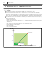
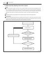
Control Outline
Learning is automatically performed every 2,000 km with the engine in an idle state. Rail pressure is raised
in order from 35 MPa to 65 MPa, and finally to 95 MPa with learning being performed at each of the three
pressure levels. Actual learning takes place under the following control flow.
Operation Section
2 21
Determinations for Learning Conditions
Learning is performed when the engine is in an idle state and all environmental conditions such as temperature are satisfied.
The figure below shows the specific details for each learning determination.
Performing Multiple Injections
Learning is performed when the engine is in an idle state and all environmental conditions such as temperature are satisfied.
The figure below shows the specific details for each setting.
Learning Correction Quantity Calculation
The learning correction quantity is calculated by detecting the difference between the injection command
value setting for multiple injections and the actual injection quantity (standard injection quantity) necessary to achieve equilibrium with the target idle rotational speed.
The figure below shows the processing for the aforementioned corrections.
2 22
Operation Section
Reflection of the Learning Correction Quantity
In this process, the learning correction quantity is reflected in the command injection pulse width (TQ) so
that the actual injection quantity becomes the target injection quantity. The figure below shows the processing for the aforementioned corrections.
[ REFERENCE ]
In addition to the learning performed automatically at three different pressure levels, the learning performed
by a dealer (with diagnostic tools) when an injector or the engine ECU is replaced adds learning at 140
MPa and 197 MPa for a total of five different levels.
However, learning at 140 MPa and 197 MPa is performed while the engine is in an idle-up state with an
eye towards supply pump reliability.
Operation Section
2 23
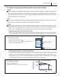
7.3 Injector Temperature Characteristic Correction Control
Outline
Injectors possess a characteristic under which the injection quantity changes according to the fuel temperature. As a result of fluctuations in this characteristic, a disparity occurs between the injection quantity command value and the actual injection quantity. Injector temperature characteristic correction control corrects
any discrepancies due to temperature.
Goal
To achieve the combustion target and to stabilize engine performance (emissions, output) by minimizing injection quantity discrepancies caused by fuel temperature fluctuations.
Control
Control takes place as follows: 1) fuel temperature inside the injector is estimated, 2) the difference is calculated between the command injection quantity and the actual injection quantity at the estimated fuel temperature, 3) the calculated difference is passed along to injector control as the correction quantity.
1) Estimating Fuel Temperature Inside the Injector
Injectors are heavily influenced by the engine temperature (roughly equivalent to engine coolant temperature). Additionally, combustion heat and heat generated by injector leak also act as influencing factors.
2) Calculating the Difference in Injection Quantities
To calculate the difference in injection quantities, first the actual injection quantity is estimated from the
following: 1) the fuel temperature estimated in step 1 and, 2) the injection conditions (rail pressure, command injection quantity) from the pre-adjusted injection quantity fluctuation characteristics map. Finally
the actual quantity is used to calculate the difference with the command quantity.
2 24
Operation Section
3) Calculating the Difference in Injection Quantities
The calculated difference in injection quantities is passed along to injector actuation control to adjust the
actuation pulse duration for each injection stage.
Operation Section
2 25
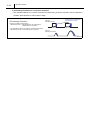
7.4 Interval Dependence Correction
Outline
The interval dependence correction compensates for fluctuations in the post-injection quantity due to pressure pulsations that occur when an injector nozzle seats.
Control Outline
The interval dependence correction performs control by calculating the pre-adjusted injection quantity correction based on the following: 1) the length of the high-pressure fuel path from the injector nozzle to the rail,
2) the pressure pulsation transmission interval calculated from the fuel environmental conditions (fuel temperature and pressure), and 3) injection conditions (fuel pressure, fuel injection quantity, injection interval).
2 26
Operation Section
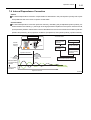
7.5 Exhaust Gas Recirculation (EGR) Control
Outline
EGR control decreases the NOx generated in large quantities at high temperatures by recirculating the exhaust gas through the combustion chamber and lowering the combustion temperature.
Furthermore, the EGR cooler path contains an EGR valve with a DC motor to perform control that is optimized to the engine state. The EGR valve has an angle sensor that detects the valve position and outputs
corresponding signals to the ECU. The ECU sends current through the DC motor so that the valve opens
to the appropriate angle.
Operation Section
2 27
7.6 i-stop Control
Outline
i-stop control is a system that automatically stops and starts the engine when the vehicle is not moving to
improve fuel economy, reduce exhaust gas, and decrease idling noise.
i-stop Operating Conditions
i-stop operates under the conditions shown below.
Engine Stop Conditions
Brake pedal depressed
AT
Engine Restart Conditions
When any of the following are detected:
Shift position in the "D" or "M" range
Foot released from the brake pedal
Accelerator pedal not depressed
Shift position in the "P" or "N" range
Vehicle speed within a predetermined range
Accelerator pedal depressed
(0 km/h)
Accelerator pressed while in the "D" or "M"
Coolant temperature within a predetermined
range
range (30°C ~ 110°C)
Shift position changed
A/C set temperature at a value other than
("P" or "N" range - "D", "M" or "R" range)
MAX or MIN
When A/C set temperature is changed to
Battery voltage at least 11.2 V
MAX or MIN
Steering angle 65° or less left to right
Altitude 1,500 m or less
Brake pedal depressed
MT
When any of the following are detected:
Shift position in the "N" range
Clutch pedal depressed
Accelerator pedal not depressed
Accelerator pedal depressed
Vehicle speed within a predetermined range
When A/C set temperature is changed to
(0 km/h)
MAX or MIN
Coolant temperature within a predetermined
Change in vehicle speed
range (30°C ~ 110°C)
A/C set temperature at a value other than
MAX or MIN
Battery voltage at least 11.2 V
Steering angle 65° or less left to right
Altitude 1,500 m or less
2 28
Operation Section
Improved Engine Restarts When Under i-stop Control
Smooth startability is required when restarting the engine with i-stop control. Therefore, the crankshaft position sensor identifies the cylinder prior to top dead center of compression so that injection to that cylinder
can be pinpointed.
Operation Section
2 29
8. Other Controls
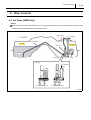
8.1 Jet Pump (4WD Only)
Outline
When the fuel tank main-side level is low, the jet pump feeds fuel from the sub-tank side to the main side
so that the fuel level inside the tank is always stable.
2 30
Operation Section
9. Exhaust Gas Treatment System
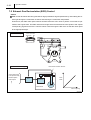
9.1 Diesel Particulate Filter (DPF) System
The DPF system efficiently traps and purifies Particulate Matter (PM), CO, and HC contained in diesel engine exhaust gas. The DPF system comes with PM forced regeneration control that allows exhaust gas to
be purified according to driving conditions.
(1) System Configuration
Electronic Control Configuration
Sensors: Exhaust gas temperature sensor, differential pressure sensor (non-DENSO products)
ECU: Engine ECU
Actuators: Injectors
Mechanical Configuration (Non-DENSO Products)
DPF, Oxidation catalyst
Operation Section
2 31
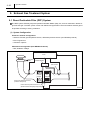
(2) Sensors
Exhaust Gas Temperature Sensors
Exhaust gas temperature sensors are installed before and after the oxidation catalyst to detect the exhaust gas temperature across the DPF. Temperature increase control signals are sent by the sensors to
the engine ECU for use in NOx reduction and PM regeneration. The exhaust gas temperature sensor is
a thermistor element in which the resistance value changes according to temperature variations.
(3) Operation Outline
Fuel injection patterns are optimized by using the common rail type fuel injection system so that afterinjection increases the exhaust gas temperature to approximately 250°C, even from low exhaust gas temperatures. Post-injection adds HC to the catalyst to further increase the DPF temperature to 650°C, or
the PM self-combustion temperature, thereby enabling the PM trapped in the DPF to be regenerated in
a short time period.
Operation Section
2 32
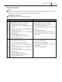
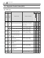
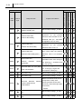
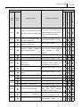
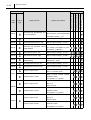
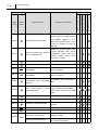
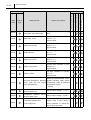
10. Diagnostic Trouble Codes (DTC)
10.1 DTC List
DTC
Fail-Safe
SAE
Check
Code
Light
Diagnosis Item
Judgment Conditions
Crank- cam pulse input
P0016
Speed-G phase gap malfunction
relative position abnormality
Crank-cam error correction quantity > 15°CA
A/F sensor heater abnormality: Actuation circuit voltage
P0030
high
A/F sensor heater abnormality: Actuation circuit voltage
low
Two-stage turbocharger
P0034
> 0.25 V (battery voltage)
compressor bypass valve:
open circuit, ground short
< 0.25 V (battery voltage)
Actuation circuit voltage
< 0.35 V (battery voltage)
Two-stage turbocharger
P0035
compressor bypass valve:
Actuation circuit current > 5.9 A
+B short
Two-stage turbocharger
P0047
regulator valve:
open circuit, ground short
Actuation circuit voltage
< 0.35 V (battery voltage)
Two-stage turbocharger
P0048
regulator valve:
Actuation circuit current > 5.9 A
+B short
Two-stage turbocharger
P004C
wastegate valve:
ground short
Actuation circuit voltage
< 0.35 V (battery voltage)
Two-stage turbocharger
P004D
wastegate valve:
Actuation circuit current > 3.5 A
+B short
P0072
A/C ambient temperature sensor:
low
Sensor output voltage
0.182 V
Operation Section
DTC
Fail-Safe
SAE
Check
Code
Light
P0073
P0079
Diagnosis Item
A/C ambient temperature sensor
high
Exhaust VVL valve ground short
Judgment Conditions
Sensor output voltage
4.886 V
Actuation circuit voltage <
0.35 V (battery voltage)
Difference
in
temperature
between the intake air temperaP007B
Abnormal intake air sensor char- ture sensor (with Mass Air Flow
acteristics
[MAF] meter) and the intake air
temperature sensor (intake manifold)
P007C
P007D
P0080
Intake air temperature sensor:
low
Intake air temperature sensor:
high
Exhaust VVL valve +B short
50°C
Sensor output voltage
0.041 V
Sensor output voltage
4.900 V
Actuation circuit current > 5.9 A
Rail pressure divergence (under-
P0087
Rail under-pressure abnormality
shoot side)
threshold level (ex.: 30 MPa)
state continues
Rail pressure divergence (over-
P0088
Rail over-pressure abnormality
shoot side)
threshold level (ex.: 30 MPa)
state continues
P0089
Rail high-pressure abnormality
Actual rail pressure > 217 MPa
Difference with calculated value
P0093
Fuel leak
for high-pressure fuel consumption (every 90°CA) > threshold
level (ex.: 120 mm3/st)
Difference in temperature between
P0096
P0097
2 33
Abnormal intake manifold temperature sensor characteristics
Intake air temperature sensor
(intake manifold): low
the intake air temperature sensor
(with Mass Air Flow [MAF] meter)
and the intake air temperature sensor (downstream of I/C)
50°C
Sensor output voltage
0.044 V
Operation Section
2 34
DTC
Fail-Safe
SAE
Check
Code
Light
P0098
Diagnosis Item
Judgment Conditions
Intake air temperature sensor
(intake manifold): high
Sensor output voltage
4.900 V
Number of MOS switch actuation
detections
pressure relief valve
for
the
pressure
reduction valve actuation circuit >
coil short abnormality
threshold level (ex.: 190 times,
energization time: 10 msec)
P009B
Number of MOS switch actuation
pressure relief valve
actuation line abnormality
detections
for
the
pressure
reduction valve circuit < 4
Downstream voltage for the actu-
pressure relief valve
ation circuit when the pressure
MOS short abnormality (ECU)
reduction valve is not actuated:
high
Pressure reduction flow volume
pressure relief valve
P009F
pressure
reduction
function
abnormality
P0101
(calculated value from change in
rail pressure) < threshold level
(ex.: 40 mm3/st)
Abnormal Mass Air Flow (MAF)
meter characteristics
Air flow volume
threshold level
(ex.: 210 mg/cyl, engine rotational speed: 2,000 rpm)
P0102
MAF meter: low
Sensor output voltage
0.289 V
P0103
MAF meter: high
Sensor output voltage
4.624 V
Difference between MAP sensor
Abnormal
P0106
Manifold
Absolute
Pressure (MAP) sensor
characteristics
(compressor outlet), atmospheric pressure sensor (built
into ECU), and exhaust gas pressure sensor
50 kPa
P0107
P0108
MAP sensor (intake manifold):
low
MAP sensor (intake manifold):
high
Sensor output voltage
0.136 V
Sensor output voltage
4.910 V
Operation Section
DTC
Fail-Safe
SAE
Check
Code
Light
Diagnosis Item
Judgment Conditions
Difference between intake air
P0111
Intake air temperature sensor
(with MAF meter) CCM diagnosis
temperature sensor (intake manifold) and intake air temperature
sensor (downstream of I/C)
50°C
P0112
P0113
Intake air temperature sensor
(with MAF meter): low
Intake air temperature sensor
(with MAF meter): high
Sensor output voltage
0.336 V
Sensor output voltage
4.511 V
Difference
P0116
between
maximum
Abnormal coolant temperature and minimum coolant temperasensor characteristics 2
tures
recorded
in
history
0.004 °C
Sensor output voltage < 0.090 V
P0117
Coolant temperature sensor: low
P0118
Coolant temperature sensor: high Sensor output voltage
4.826 V
Abnormal accelerator pedal posi- Voltage
between
P0121
P0122
P0123
difference
tion sensor 1
accelerator pedal position sen-
characteristics
sor systems 1 and 2 > 0.5 V
Accelerator pedal position sensor
Sensor output voltage
0.277 V
Sensor output voltage
4.828 V
A/F sensor + terminal: low
Sensor output voltage
0.400 V
A/F sensor - terminal: low
Sensor output voltage
0.400 V
A/F sensor + terminal: high
Sensor output voltage
4.400 V
A/F sensor - terminal: high
Sensor output voltage
4.400 V
1: low
Accelerator pedal position sensor
1: high
P0131
P0132
A/F sensor resistance value
P0133
2 35
Poor A/F sensor activation
100
(after heater activation:
less than or equal to 40 )
P0134
A/F sensor +, - terminal short
P0154
Atmospheric learning abnormality
Difference between sensor output terminal voltages
0.1 V
Deviation from atmospheric O2
concentration
36.5%
Operation Section
2 36
DTC
Fail-Safe
SAE
Check
Code
Light
P0181
Diagnosis Item
Abnormal fuel temperature sensor characteristics
Judgment Conditions
Difference
between
maximum
and minimum fuel temperatures
recorded in history
1°C
P0182
Fuel temperature sensor: low
Sensor output voltage
0.118 V
P0183
Fuel temperature sensor: high
Sensor output voltage
4.833 V
P0191
Abnormal rail pressure sensor
characteristics
Amount of change in sensor output voltage (compared to previous value)
0.00245 V
P0192
Rail pressure sensor: low
Sensor output voltage
0.514 V
P0193
Rail pressure sensor: high
Sensor output voltage
4.808 V
P0196
Abnormal oil temperature sensor Difference with coolant tempera50°C
characteristics
ture sensor
P0197
Oil temperature sensor: low
Sensor output voltage
0.211 V
P0198
Oil temperature sensor: high
Sensor output voltage
4.929 V
Injector 1 open circuit
P0201
Open circuit downstream of cylinder no. 1 injector circuit
Short in ECU internal cylinder
Cylinder switch 1 short
selection switch
for cylinder no. 1 injector
Open circuit downstream of cylin-
Injector 4 open circuit
der no. 2
injector circuit
P0202
Short in ECU internal cylinder
Cylinder switch 4 short
selection switch
for cylinder no. 2 injector
Open circuit downstream of cylin-
Injector 2 open circuit
der no. 3
injector circuit
P0203
Short in ECU internal cylinder
Cylinder switch 2 short
selection switch
for cylinder no. 3 injector
Operation Section
DTC
Fail-Safe
SAE
Check
Code
Light
Diagnosis Item
Judgment Conditions
Open circuit downstream of cylinInjector 3 open circuit
der no. 3
injector circuit
P0204
Short in ECU internal cylinder
Cylinder switch 3 short
selection switch
for cylinder no. 3 injector
P0219
P0222
P0223
Engine overrun abnormality
Accelerator pedal position sensor
2: low
Accelerator pedal position sensor
2: high
Engine rotational speed
5,670
rpm
Sensor output voltage
0.217 V
Sensor output voltage
4.147 V
The difference between the target manifold pressure and actual
P0234
Excessive supercharging (com- manifold pressure in the compact
pact turbocharger region)
turbocharger range is below the
specified value continuously for
seven seconds
Difference between MAP sensor
P0236
Abnormal MAP sensor (compres- (intake manifold), pressure sensor outlet) characteristics
sor (built into ECU), exhaust gas
pressure sensor
P0237
P0238
MAP sensor
(compressor outlet): low
MAP sensor
(compressor outlet): high
50 kPa
Sensor output voltage
0.127 V
Sensor output voltage
4.092 V
The difference between the target manifold pressure and actual
P0299
2 37
Insufficient supercharging (com- manifold pressure in the compact
pact turbocharger region)
turbocharger range exceeds the
specified value continuously for
seven seconds
Operation Section
2 38
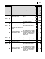
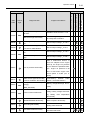
DTC
Fail-Safe
SAE
Check
Code
Light
Diagnosis Item
Judgment Conditions
The difference between the target manifold pressure and actual
P02CA
Excessive supercharging (heavy manifold pressure in the heavyduty turbocharger region)
duty turbocharger range is below
the specified value continuously
for seven seconds
The difference between the target manifold pressure and actual
P02CB
Insufficient supercharging (heavy manifold pressure in the heavyduty turbocharger region)
duty turbocharger range exceeds
the specified value continuously
for seven seconds
Difference in rotational fluctuations between cylinders > 0.212
P0301
Injector function (non-injection) 1
msec (MT vehicles; target rotational speed: 750 rpm, coolant
temperature: 80°C)
Difference in rotational fluctuations between cylinders > 0.212
P0302
Injector function (non-injection) 2
msec (MT vehicles; target rotational speed: 750 rpm, coolant
temperature: 80°C)
Difference in rotational fluctuations between cylinders > 0.212
P0303
Injector function (non-injection) 3
msec (MT vehicles; target rotational speed: 750 rpm, coolant
temperature: 80°C)
Difference in rotational fluctuations between cylinders > 0.212
P0304
Injector function (non-injection) 4
msec (MT vehicles: target rotational speed: 750 rpm, coolant
temperature: 80°C)
P0313
P0336
RDP control status 2
Remaining fuel quantity < 4 L
Crankshaft position sensor
NE pulse count between missing
pulse count abnormality
teeth does not equal 56
Operation Section
DTC
Fail-Safe
SAE
Check
Code
Light
P0337
Diagnosis Item
Judgment Conditions
Crankshaft position sensor
No NE pulse input
pulse input failure
Deviation
reverse
pulse
output
abnormality
abnormality
6 CA
Reverse rotation pulse input (during forward rotation)
Cylinder recognition sensor pulse G pulse count between extra
count abnormality
Cylinder recognition sensor pulse
count input failure
Actuation signal between ECU
P0383
tion during restart cylinder recognition
forward/reverse pulse inversion
P0342
recorded
failure engine stall and crankshaft posi-
Crankshaft position sensor
P0341
between
crankshaft position during an
Crankshaft position sensor
P0339
and glow unit:
open circuit, ground short
teeth does not equal five
No G pulse input
Actuation circuit voltage < 0.35 V
(battery voltage)
Actuation signal between ECU
P0384
and glow unit:
Actuation circuit current > 5.9 A
+B short
EGR flow volume at or below a
P0401
Low Exhaust Gas Recirculation constant value in relation to the
(EGR) flow volume abnormality
target
value
continuously
for
eight seconds
EGR flow volume at or above a
P0402
2 39
High EGR flow volume abnormal- constant value in relation to the
ity
target
value
continuously
for
eight seconds
P0404
EGR DC motor abnormality
DC motor actuation current > 8 A
P0405
EGR lift sensor: low
Sensor output voltage
0.241 V
P0406
EGR lift sensor: high
Sensor output voltage
4.856 V
Operation Section
2 40
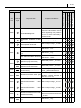
DTC
Fail-Safe
SAE
Check
Code
Light
Diagnosis Item
Judgment Conditions
Difference in exhaust gas temperature before and after passing
P0421
Oxidation catalyst diagnosis
the oxidation catalyst is at or
below the specified value continuously for between 60 and 80
seconds
Difference between MAP sensor
P0471
Abnormal exhaust gas pressure
sensor characteristics
(intake manifold), MAP sensor
(compressor outlet), and atmospheric pressure sensor (built
into ECU)
50 kPa
P0472
Exhaust pressure sensor: low
Sensor output voltage
0.117 V
P0473
Exhaust pressure sensor: high
Sensor output voltage
4.858 V
P0480
P0481
FANPWM1
malfunction Radiator fan 1 actuation duty
(FANPWM1)
stuck in high/low
FANPWM2
malfunction Radiator fan 2 actuation duty
(FANPWM2)
stuck in high/low
EGR valve (cooler side)
P0488
energization
duty
abnormality
detection
Energization duty continuously
90%
Vehicle speed signal error mes-
P0500
CAN
communication
vehicle sage received from ABS/DSC, or
speed malfunction
CAN ID217 received from ABS/
DSC
P0522
Oil pressure sensor: low
Sensor output voltage
0.135 V
P0523
Oil pressure sensor: high
Sensor output voltage
4.809 V
P0524
Oil pressure zero abnormality
P0532
A/C compressor sensor: low
Sensor output voltage
0.053 V
P0533
A/C compressor sensor: high
Sensor output voltage
4.950 V
Blow-by heater relay:
Actuation circuit voltage < 0.35 V
open circuit, ground short
(battery voltage)
P053B
BBH circuit low abnormality
Engine oil pressure is less than
30 hPa
Circuit voltage is low when there
is a relay ON command
Operation Section
DTC
Fail-Safe
SAE
Check
Code
Light
Diagnosis Item
Judgment Conditions
Blow-by heater relay:
P053C
Actuation circuit current > 1.5 A
+B short
BBH circuit high abnormality
P0545
P0546
Exhaust gas temperature sensor:
low
Abnormal exhaust gas temperature sensor characteristics
Master vacuum pressure sensor:
P0555
low
Master vacuum pressure sensor:
high
Circuit voltage is high when there
is a relay OFF command
Sensor output voltage
0.134 V
Sensor output voltage
4.96 V
Sensor output voltage
0.133 V
Sensor output voltage
4.906 V
After a determined amount of
time has elapsed since engine
start-up, the engine oil pressure
P055F
Low oil pressure abnormality
is at or below the specified value.
(Ex.: engine oil pressure is 80
kPa or less when engine rotational speed is 2,000 rpm or
lower)
P0571
Brake switch signal abnormality
Inconsistency
(1 and 2 correlation abnormality)
switch 1 and brake switch 2
Battery
P057F
deterioration
(overall
energy)
(BMS_SOHCBF)
between
brake
Battery charge/discharge abnormality
Current sensor internal abnor-
P058A
Current sensor malfunction
mality, battery voltage abnormality,
battery
fluid
temperature
abnormality
P0601
2 41
Diesel Particulate Filter (DPF) Data flash
related EEPROM abnormality
P0602
VID writing abnormality
P0605
ECU flash ROM abnormality
data corruption abnormality
Data flash
writing value abnormal
Data flash
checksum abnormal
Operation Section
2 42
DTC
Fail-Safe
SAE
Check
Code
Light
P0606
P0607
P0610
Diagnosis Item
ECU abnormality (main IC abnormality)
Judgment Conditions
Main IC run pulse input failure
ECU abnormality (monitoring IC Monitoring IC run pulse input failabnormality)
VID checksum abnormality
ure
Data flash
checksum abnormality
Engine start-up speed exceeds
P0615
Starter malfunction (ISS_STA)
the
guaranteed
performance
speed for the starter or starter
relay
SCV +B short
P062A
SCV actuation system abnormality
P062B
Injector actuation circuit D3P
communication abnormality
Diagnosis signal fixed at high
Diagnosis signal fixed at low
Communication
abnormal
between injector actuation IC
and ECU
P0642
Sensor voltage 1: low
Sensor output voltage
3.894 V
P0643
Sensor voltage 1: high
Sensor output voltage
4.115 V
A/C magnetic clutch relay:
Actuation circuit voltage < 0.35 V
open circuit, ground short
(battery voltage)
P0646
P0647
A/C magnetic clutch relay:
+B short
Actuation circuit current > 1.5 A
P0652
Sensor voltage 2: low
Sensor output voltage
3.894 V
P0653
Sensor voltage 2: high
Sensor output voltage
4.115 V
Sensor output voltage
0.100 V
Sensor output voltage
4.900 V
P0668
P0669
P0670
P0671
ECU internal temperature sensor: low
ECU internal temperature sensor: high
Glow unit control
Abnormality due to diagnosis sig-
circuit abnormality
nal from glow unit
No. 1 cylinder glow plug circuit Abnormality due to diagnosis sigabnormality
nal from glow unit
Operation Section
DTC
Fail-Safe
SAE
Check
Code
Light
P0672
P0673
P0674
Diagnosis Item
Judgment Conditions
No. 2 cylinder glow plug circuit Abnormality due to diagnosis sigabnormality
nal from glow unit
No. 3 cylinder glow plug circuit Abnormality due to diagnosis sigabnormality
nal from glow unit
No. 4 cylinder glow plug circuit Abnormality due to diagnosis sigabnormality
nal from glow unit
DI signal between ECU and glow Glow unit diagnosis signal
P0683
stuck high
stuck high
DI signal between ECU and glow Glow unit diagnosis signal
stuck low
P0684
stuck low
No DI signal connection between Glow unit diagnosis signal
ECU and glow
not received
Data flash read/write abnormality
P06B8
Data flash abnormality
Data
flash
writing
counts
325,000 times
P06DB
P06DC
P06DD
P06DE
Variable relief oil pump valve:
Actuation circuit voltage < 0.35 V
ground short
(battery voltage)
Variable relief oil pump valve:
+B short
Actuation circuit current > 5.9 A
Oil pump switching high-pressure Engine oil pressure exceeds 250
abnormality
hPa
Oil pump switching low-pressure Engine oil pressure is less than
abnormality
250 hPa
No brake switch input even
though the vehicle has been
P0703
Brake switch diagnosis
stopped several times at or
above a constant vehicle speed
value
No clutch switch input even
though the vehicle has been
P0704
Clutch switch diagnosis
stopped several times at or
above a constant vehicle speed
value
P07BE
2 43
Neutral switch malfunction
Inconsistency between neutral
switch, neutral sub-switch
Operation Section
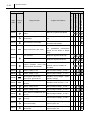
2 44
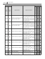
DTC
Fail-Safe
SAE
Check
Code
Light
Diagnosis Item
Judgment Conditions
No neutral switch input even
P0850
Neutral switch diagnosis
though there have been several
clutch switch inputs at or above a
constant vehicle speed value
P0A0F
IR run failure (ISS_IRFAIL)
i-stop
i-stop restart fault
When the battery voltage, ECU
P0A8D
Decreased battery voltage
control voltage, or DC-DC converter control voltage is low at
engine start-up
P0A94
DC-DC
malfunction
(DCDC_FAIL1)
Abnormality received in communications from the DC-DC converter
When the water level switch (with
P1140
Water level switch diagnosis
P115A
RDP control status 1
Remaining fuel quantity < 5 L
P115B
RDP control status 3
Remaining fuel quantity < 3.9 L
P1196
Main relay abnormality
P1200
fuel filter) is ON
Main relay stuck high
during main relay OFF command
Learning incomplete (failure to Incomplete injector microinjection
finish learning)
Q learning
P1260
Immobilizer abnormality
Immobilizer verification failure
P1282
Pump protective fail plug
P1303
EGR valve initialize abnormality
P1329
Pump replacement fail flag
Actual rail pressure > threshold
level (ex.: 123 MPa, 750 rpm)
Failure to learn EGR valve fully
closed position
Actual rail pressure
threshold
level (ex.: 200 MPa, 750 rpm)
Wastegate valve is open when
P132E
Wastegate valve function diagno- there is a wastegate valve close
sis
command in the compact turbocharger region
Operation Section
DTC
Fail-Safe
SAE
Check
Code
Light
Diagnosis Item
Cylinder
P1336
recognition
Judgment Conditions
sensor
installation phase disparity abnor- NE-G phase deviation > 4.56°CA
mality
P1378
Injector low charge
P1379
Injector overcharge
P1589
P1675
injector
actuation
circuit
charge voltage
High injector actuation circuit
charge voltage
Target opening - actual opening
sticking abnormality
4.2°
QR data write failure abnormality
No injector QR correction data
Injector QR correction data
checksum abnormality
QR correction information input Injector QR correction data
abnormality
P167B
Low
Intake throttle valve
QR data abnormality
P1676
range abnormality
Learning execution failure (failure Injector microinjection Q learning
to start)
cannot be executed
Clutch stroke sensor: low
Sensor output voltage
0.202 V
Clutch stroke sensor: high
Sensor output voltage
4.852 V
P176E
Inconsistency between the clutch
Clutch malfunction (ISS_CLAB)
switch, clutch cut switch, clutch
stroke sensor
P1905
P2002
P2032
Test terminal short
Differential pressure type DPF
diagnosis
Upstream oxidation catalyst tem-
Test terminal ON
Pressure difference across the
DPF is less than the specified
value
Sensor output voltage
0.107 V
istics upstream of oxidation cata- Sensor output voltage
4.960 V
perature low
Abnormal temperature character-
P2033
lyst
P2101
P2105
2 45
DC motor overcurrent abnormality
Overrun diagnosis
DC motor actuation current > 8 A
Engine rotational speed
rpm when the key is OFF
1,000
Operation Section
2 46
DTC
Fail-Safe
SAE
Check
Code
Light
P2118
Diagnosis Item
Judgment Conditions
Intake throttle valve
Energization duty continuously
energization duty abnormality
90%
Open circuit upstream of cylin-
P2146
COM1 open circuit
ders no. 1, 4
injector circuit
Ground short upstream of cylin-
P2147
COM1 ground short
ders no. 1, 4
injector circuit
+B short upstream of cylinders
P2148
COM1 +B short
no. 1, 4
injector circuit
Open circuit upstream of cylin-
P2149
COM 2 open circuit
ders no. 2, 3
injector circuit
Ground short upstream of cylin-
P2150
COM 2 ground short
ders no. 2, 3
injector circuit
+B short upstream of cylinders
P2151
COM 2 +B short
no. 2, 3
injector circuit
Difference between MAP sensor
Abnormal atmospheric pressure (intake manifold), MAP sensor
P2227
sensor (built into the engine (compressor outlet), and exhaust
gas pressure sensor
ECU) characteristics
50 kPa
P2228
P2229
Atmospheric
pressure
sensor
(built into ECU): low
Atmospheric
pressure
(built into ECU): high
sensor
Sensor output voltage
1.151 V
Sensor output voltage
4.656 V
Turbocharger
P2261
compressor
Compressor bypass valve
bypass valve is open during a
function diagnosis
close command, or closed during an open command
Operation Section
DTC
Fail-Safe
SAE
Check
Code
Light
Diagnosis Item
Judgment Conditions
Difference between the target
P2263
regulating valve position and the
Regulator valve
actual regulating valve position is
lift feedback diagnosis
10 mm or more continuously for
three seconds
P242C
P242D
Temperature upstream of DPF
low
Abnormal temperature characteristics upstream of the DPF
DPF PM accumulation abnormality 3
P242F
DPF PM accumulation abnormality 4
DPF PM accumulation abnormality 5
Differential
P244A
pressure
sensor
upstream piping abnormality
Differential
pressure
sensor
upstream piping abnormality
P2452
P2453
Sensor output voltage
0.107 V
Sensor output voltage
4.960 V
PM volume
17 g/L
PM volume
17 g/L
PM volume
100 g/L
Differential pressure
0.2 kPa
Differential pressure
0.2 kPa
Differential pressure sensor off- Differential pressure
set abnormality
5 kPa
Differential pressure sensor gain
abnormality
Differential
P2454
-5 kPa
differential pressure
Differential pressure
threshold
level (ex.: 100 kPa, exhaust gas
flow rate: 10 m3/min)
pressure
upstream/downstream
sensors
of
DPF Sensor output voltage
0.217 V
low
Differential
P2455
pressure
upstream/downstream
sensors
of
DPF Sensor output voltage
4.843 V
high
P2456
P2458
2 47
Differential pressure sensor intermediate abnormality
DPF PM accumulation abnormality 1
Difference between differential
pressure maximum and minimum
0.1 kPa
PM volume
10 g/L
Operation Section
2 48
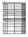
DTC
Fail-Safe
SAE
Check
Code
Light
P245A
Diagnosis Item
EGR valve (cooler side)
DC motor status abnormality
EGR
P245B
P2463
Judgment Conditions
DC motor temperature
abnormality
DC motor actuation current > 8 A
DC motor actuation current > 8 A
EGR bypass valve (ECU side)
Energization duty continuously
high duty abnormality diagnosis
95%
DPF PM accumulation abnormality 2
PM volume
13 g/L
Oil dilution quantity (calculated
P246C
from injection quantity)
Oil dilution 6
thresh-
old level (Ex.: 16,751 g, intake air
temperature: 20°C)
P2494
EGR lift sensor 2: low
Sensor output voltage
0.168 V
P2495
EGR lift sensor 2: high
Sensor output voltage
4.870 V
EGR feedback abnormality
P24A5
Energization duty continuously >
69%
EGR valve position sensor output
EGR bypass valve stuck open
value is not at fully closed during
a fully closed command
When the alternator generated
P2502
B terminal open circuit warning voltage is at least 17 V and the
(ALC_BOPEN)
battery voltage is 11 V or less
continuously for five seconds
Alternator generated current is
between 8 to 5 V or less continu-
P2503
malfunction ously for five seconds, regardless
Alternator
of whether or not the alternator
(ALC_ALTTF)
target power generation current
is 20 A or more
Alternator generated voltage is at
P2504
Excessive
voltage
(ALC_OVCHG)
warning least 18.5 V, or battery voltage is
16 V or more continuously for five
seconds
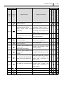
Operation Section
DTC
Fail-Safe
SAE
Check
Code
Light
Diagnosis Item
Back-up memory
P2507
power supply malfunction determination (PBATTF)
P252F
Oil dilution
Oil dilution 2
Judgment Conditions
Back-up power supply voltage
1/4 battery voltage
Oil dilution quantity (calculated
from injection quantity)
1,161 g
Oil dilution quantity (calculated
from injection quantity)
2,236 g
Oil dilution quantity (calculated
P253F
Oil dilution 5
from injection quantity)
thresh-
old level (ex.: 16,751 g, intake air
temperature: 20°C)
Engine oil pressure has dropped
Oil dilution
50 kPa or more compared to
when the oil was changed
P2564
P2565
P2610
P2621
P2622
U0073
U0074
VNT lift sensor: low
(two-stage turbocharger)
VNT lift sensor: high
(two-stage turbocharger)
Sensor output voltage
0.214 V
Sensor output voltage
4.786 V
Soak timer abnormality diagnosis HEC internal failure detection
Intake throttle valve
position sensor: low
Intake throttle valve
position sensor: high
Sensor output voltage
0.113 V
Sensor output voltage
4.812 V
CAN 1 communication bus off When the HS-CAN (public) bus is
abnormality
off
CAN 2 communication bus off When the HS-CAN (private) bus
abnormality
is off
CAN 1 communication no TCM When the CAN (public) message
U0101
reception abnormality
is not received from TCM
CAN 2 communication no TCM When the CAN (private) mesreception abnormality
U0104
2 49
sage is not received from TCM
CAN 1 communication no PCS When the CAN message is not
reception abnormality
received from PCS
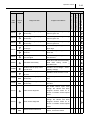
Operation Section
2 50
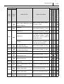
DTC
Fail-Safe
SAE
Check
Code
Light
U0121
U0131
U0140
U0151
U0155
U0214
U0235
U0298
U0302
U0305
Diagnosis Item
CAN 1 communication no DSC When the CAN message is not
reception abnormality
received from DSC
CAN 1 communication no EPAS When the CAN message is not
reception abnormality
received from EPAS
CAN 1 communication no FBCM When the CAN message is not
reception abnormality
received from FBCM
CAN 1 communication no RCM When the CAN message is not
reception abnormality
received from RCM
CAN 1 communication no HEC When the CAN message is not
reception abnormality
received from HEC
CAN 1 communication no SSU When the CAN message is not
reception abnormality
received from SSU
CAN 1 communication no CVM When the CAN message is not
reception abnormality
received from CVM
DC-DC communication error
CAN
communication
CAN
communication
abnormality
diagnosis
U0320
U0323
U0336
U0338
U0433
communication
CNTCS
communication
checksum abnormality from PCS
communication
communication
When there is a CAN message
checksum
abnormality
from
EPAS
CNTCS When there is a CAN message
checksum abnormality from HEC
CNTCS When there is a CAN message
abnormality diagnosis (RCM)
CAN
checksum abnormality from TCM
DSC
abnormality diagnosis (HEC)
CAN
communication error from FBCM
(ABS/ checksum abnormality from ABS/
abnormality diagnosis (EPAS)
CAN
information
CNTCS When there is a CAN message
DSC)
CAN
converter
CNTCS When there is a CAN message
abnormality diagnosis (PCS)
communication
DC-DC
CNTCS When there is a CAN message
abnormality diagnosis (TCM)
CAN
U0315
Judgment Conditions
checksum abnormality from RCM
CNTCS When there is a CAN message
abnormality diagnosis (SSU)
checksum abnormality from SSU
ICA updatebit fail determination i- Correct data cannot be received
stop
from RBCM
Operation Section
DTC
Fail-Safe
SAE
Check
Code
Light
Diagnosis Item
Judgment Conditions
HEC not configured or correct
U2300
GCC abnormality diagnosis
data cannot be received from
HEC
U3000
B10A2
2 51
Immobilizer abnormality
Data
flash
three-point
check
abnormality
History of fuel cut-off control Fuel cut-off command received
operation during a collision
from RCM
2 52
Operation Section
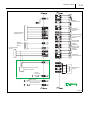
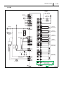
11. Wiring Diagrams
11.1 Engine ECU External Wiring Diagrams
(1) AT
Operation Section
2 53
2 54
Operation Section
Operation Section
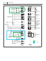
(2) MT
2 55
2 56
Operation Section
Operation Section
2 57
2 58
Operation Section
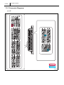
11.2 Connector Diagrams
(1) AT
Operation Section
(2) MT
2 59
Service Division DENSO CORPORATION
1-1, Showa-cho, Kariya-shi, Aichi-ken, 448-8661, Japan
06K500S