1
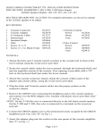
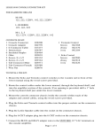
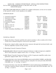
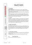
CONSOLE CONNECTOR KIT 7281 INSTALLATION INSTRUCTIONS
FOR USE WITH: HAMMOND T-500 Organs
LESLIE Speaker Models 110, 120, 125, 145, 147, 225, 247
KIT CONTENT
Console Connector Assembly
Console Adapter
Cable Assembly, 6-conductor, 30-foot
Hardware Package
Screw, wood, 6 x 1/2,
Phillips head (4)
Screw, sheet metal, 8 x 1/2,
Phillips head (2)
Staple, insulated (8)
012617
109140
017277
045989
029124
029132
028464
Tremolo Control
brown
012625
ebony
012633
ivory
012641
Echo Control
brown
029397
ebony
029405
ivory
029413
Oiler
053025
- CAUTION
Due to the presence of electrical charges and the danger of moving mechanical parts,
installation procedures or adjustments requiring work inside the LESLIE speaker
cabinet or the organ console should be performed ONLY BY a service man authorized
by the dealer or factory to perform such work.
INSTALLATION
CAUTION: DISCONNECT ORGAN POWER BEFORE PROCEEDING!
1. Mount the echo and tremolo control switches to the wooden rail in front of the
lower manual, using the wood screws provided.
2. Route the control cables under the lower manual, through the keyboard shelf, and
into the amplifier section of the console. If no opening is provided, drill a 7/8"
hole in the keyboard shelf just under the lower manual.
3. Mount the console connector chassis inside the console within reach of the
adapter and control cables, using the wood screws provided.
4. Plug the echo and tremolo control cables into the proper sockets on the connector
chassis.
5. Remove the GREEN wire connecting the headphone jack to the console speakers
and connect it to the RED adapter wire (A). Insulate with the plastic sleeve
provided.
6. Connect the GREEN adapter wire to the terminal previously occupied by the green
headphone jack wire (B).
Page 1 of 4
7. Insert the adapter plug into the socket on the rear apron of the console amplifier.
8. Fit the adapter socket on the plug marked CONSOLE, on the connector chassis.
9. Plug the LESLIE speaker cable into the socket marked LESLIE SPEAKER, on the
connector chassis.
10. Set the speaker load resistor to the 8-0HM position as outlined in the LESLIE
service manual.
11. Adjust speaker volume as outlined in the LESLIE service manual.
The installation is now complete.
SWITCH POSITION
ECHO
ENSEMBLE
MAIN
CONTACTS MADE
RED/BLACK
RED/BLACK;
WHITE/BLACK
WHITE/BLACK
Page 2 of 4
Ordering Parts
Standard hardware, connectors, and electronic components should be purchased
locally. Non-standard items may be obtained through a LESLIE speaker dealer. Orders
should include part numbers as listed.
PARTS LIST
Fuseholder
Fuse
Chassis Cover
Chassis
S3 Socket, 5-contact
P2 Plug, 5-pin
S4 Socket, 6-contact
055178
029280
026054
012674
029652
025437
060459
P1 Plug, 9-pin
S1 Socket, 5-contact
S1 Cap
Tab, female
Tab, male
024653
029264
013136
029389
029371
S5 Socket, 2-contact
029298
Page 3 of 4
ECHO CONTROL
TREMOLO CONTROL
Echo Switch Case
brown
ebony
ivory
Switch Case Cover
brown
ebony
ivory
Switch Knob
brown
ebony
Switch Retainer (2)
Switch Only
5-pin Plug
Tremolo Switch Case
brown
ebony
ivory
Switch Case Cover
brown
ebony
ivory
103750
103760
103770
048702
048710
048728
Switch Knob
048066
048074
048116
010249
021238
brown
ebony
Switch Retainer (2)
Switch Only
2-pin Plug
103750
103760
103770
048702
048710
048728
048066
048074
048108
042911
029165
PARTS LIST: 017277 CABLE ASSEMBLY
Plug, 6-pin
061721
Socket, 6-pin
029546
Cap Body
022046
Clamp, cut
022079
Screw, machine, 6-32 x 3/8
027979
MULTIPLE SPEAKER INSTALLATION
For complete information, see the service manual for the LESLIE speaker to be added.
Page 4 of 4