1
LESLIE 9100 CONSOLE CONNECTOR KIT INSTALLATION INSTRUCTIONS
For Use With: HAMMOND Models A-100, RT2, RT3, D-100
LESLIE 900 Speaker
MULTIPLE SPEAKER INSTALLATION: For complete information, see the service manual
of the specific mode1 Leslie speaker to be added.
CONTENTS OF KIT:
1 Console Connector
1 Extension Cable
1 9-Conductor Cable
1 Instructions
10 Insulated Staples
1 Oiler
4 Screws, 8 X 1/2
6 Screws, 8 X 1/2
12 Wire Nuts
1 Cable Assembly, Red/Black, 24"
043604
043612
021600
043661
028464
053025
029132
029124
028076
043679
1 Reverb Control
brown
042564
ebony
042572
ivory
042580
1 Tremolo
brown
ebony
ivory
Control
042606
042614
042622
1 Echo Control
brown
032243
ebony
032250
ivory
03226B
TO INSTALL THE KIT:
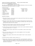
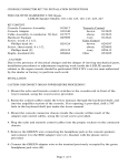
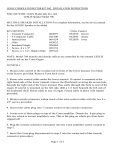
1. Mount the Echo, Tremolo and Reverb control switches to the wooden rail in front
of the lower manual using the wood screws provided.
2. Route the control cables under the lower manual, through the keyboard shelf, and
into the amplifier section of the console.
3. Mounting Console Connector Chassis:
D-100, RT2, RT3: Mount Console Connector Chassis to right of organ pre-amplifier
above tone generator support shelf. (See "I" on Figs. 1 and 2).
A-100: Mount Console Connector Chassis to left of organ pre-amplifier under tone
generator support shelf. (See "I" on Fig. 3).
4. Connect the three wires from the REVERB control and the RED, WHITE, and BLACK
TWISTED wires from the connector chassis using the wire nuts provided. MATCH
COLORS. (see "A" on Figs. 1,2 and 3) .
5. Connect the three wires from the TREMOLO control and the three JACKETED wires
from the connector chassis using the wire nuts provided. MATCH COLORS. (See "B"
on Figs. 1,2 and 3).
Page 1 of 5
6. Connect the four wires from the ECHO control and the four JACKETED wires from
the connector chassis using the wire nuts provided. MATCH COLORS. (See "C" on
Figs. 1, 2 and 3).
7. Connect the BLUE and GRAY extension cable wires to the 117VAC terminals behind
the protective cover on the console Pre-amp. (See "D" on Figs. 1, 2, and 3).
8. Connect the BLACK connector wire to the "GND" terminal on the console Pre-amp.
(See "E" on Figs. 1,2 and 3).
9. Remove the RED and BLACK wires from the two "G" terminals on the console Preamp and connect them to the two screw terminals on the connector chassis. (See
"F" on Figs. 1, 2 and 3) .
10. Strip ends of red and black wires removed from "G" Terminals. Now add them to
matching red and black leads supp1ied in hardware package, using the two wire
nuts provided. Connect ends of these extension wires to the two screw terminals
on connector chassis. (See "F" on Figs. 1, 2 and 3).
11. Connect the two RED connector wires to the two "G" terminals on the console Preamp. (See "G" on Figs. 1, 2 and 3).
NOTE: Terminals in steps 8-11 may be solder-type terminals. If this is the case,
remove the spade lugs from the connector wires and solder the wires to the
terminals.
12. P1ug the Leslie Speaker cable into the socket on the extension chassis.
13. Adjust the volume as outlined on the speaker back card and in the Leslie Service
Manual. The installation is now complete.
Page 2 of 5
Page 3 of 5
Page 4 of 5
PARTS LIST
CONSOLE CONNECTOR
CONSOLE ADAPTER
Chassis
Circuit Assy
S1
S1, Insert
C1
C2, C4
C3
C5
C6
C7
R1
R2, R3
R4
R5
R6
R7, R8
R9
Q1, Q2
Q3
042390
042457
042119
023556
028589
028431
025262
031294
060467
022251
022277
028373
018036
042549
024133
028530
028571
061366
033563
043612 Extension
Chassis
S2
P1
P1 Insert
043646
061713
023259
023309
ECHO CONTROL
TREMOLO CONTROL
REVERB CONTROL
Echo Switch Case
brown
029199
ebony
029207
ivory
029215
Switch Case Cover
brown
048702
ebony
048710
ivory
048728
Switch Knob
brown
048066
ebony
048074
Tremolo Switch Case
brown
040543
ebony
040550
ivory
040568
Switch Case Cover
brown
048702
ebony
048710
ivory
048728
Switch Knob
brown
048066
ebony
048074
Reverb Switch Case
brown
040576
ebony
040584
ivory
040592
Switch Case Cover
brown
048702
ebony
048710
ivory
048728
Switch Knob
brown
048066
ebony
048074
Switch Retainer (2)
Switch Only
048116
029173
Switch Retainer (2)
Switch Only
048116
029173
Switch Retainer (2) 048116
Switch Only
029173
ORDERING PARTS:
Standard hardware, connectors, and electronic components should be purchased
1ocally. Non-standard items may be obtained through a Leslie speaker dea1er. Orders
should include part numbers shown above.
Page 5 of 5