1
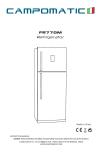
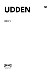
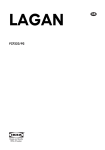
900 & 9100 Series
Refrigerators
Installation Requirements
for Models:
9162 9163 9182 9183
962 963 982 983
WARNING
Improper installation, adjustment, alteration, service, or maintenance can cause
injury or property damage. Read this manual. For assistance or additional information
consult a qualified installer, service agency, or a gas supplier.
NORCOLD
P O BOX 4248
SIDNEY OH 45365-4248
Part No.: 618474B (96-03)
Table of contents
Safety Awareness ........................................ 2
Gas Supply and Connection......................... 7
Product Specifications.................................. 3
120 Volt AC Supply and Connection............ 8
Certification and Codes................................ 3
12 Volt DC and Supply Connection.............. 8
Preparing for Installation .............................. 4
Supply Wire and Fuse Size.......................... 9
Certified Enclosure Requirements ............... 4
Door Panels ................................................ 9
Ventilation Requirements ............................. 4
Test Gas Supply Piping................................ 9
Certified Vents and Dimensions................... 5
Flame Failure Safety Device Check............10
Certified Vent Installation ............................. 5
Hypot Test....................................................10
Optimum Clearance Requirements.............. 6
Lighting Instructions ..............................10, 11
Alternate Construction.................................. 6
Diagnostic Codes and Meanings .........10, 11
Combustion Seal/Trim Piece........................ 7
Read this manual carefully and become thoroughly acquainted with its contents before installing this refrigerator.
NOTICE: THIS APPLIANCE IS NOT APPROVED FOR USE AS A FREE-STANDING REFRIGERATOR OR FOR MARINE APPLICATIONS. THIS APPLIANCE IS EQUIPPED FOR
LP GAS AND CANNOT BE CONVERTED TO ANY OTHER FUELS (NATURAL GAS,
BUTANE, ETC.).
Safety Awareness
Be alert to potential Safety Hazards when the Safety Alert Symbol
manual.
appears on the refrigerator or in this
A signal word (i.e. Warning or Caution) accompanying the Safety Alert Symbol identifies the severity of the Safety
Hazard. Review the safety symbols and signal words below. Carefully read their descriptions to understand their
meaning. They are for your safety.
Warning indicates the presence of a hazard that can cause severe personal injury, death, or
substantial property damage if ignored.
Caution indicates the presence of a hazard that will or can cause minor personal injury or
substantial property damage if ignored.
• Improper installation, adjustment, alteration, and unauthorized or improper servicing and maintenance of this
refrigerator can cause severe personal injury, property damage, or both.
• Propane gas can cause an explosion that can result in property damage, personal injury or death. Never smoke
or light a flame when working gas appliances.
• Ground the 120 VAC circuit in compliance with any applicable local, state, or national codes. Never cut or remove
the round grounding prong from the refrigerator’s AC power cord. Do not use a two-prong adapter. Do not use
an extention cord.
• Protect all wiring from physical damage, vibration, and excessive heat.
• Keep liquids away from electrical connections. Many liquids are electrically conductive and could cause serious
arcing damage and fires.
2
• Never bend, drop, drill, weld, manipulate, or hammer the refrigerant system. Doing so can cause the system to
rupture, releasing chemicals that can irritate eyes and skin.
• This refrigerator has sharp edges and corners at the rear. Use care when working on this refrigerator. To prevent
cuts or abrasions, wear cut resistant gloves.
be strong enough to support the combined weight of the refrigerator and its food load.
• Never install the refrigerator directly on carpeting. To protect carpeting, the refrigerator must be placed on a
metal or wood panel extending at least the full width and depth of the refrigerator.
• When discarding an appliance, remove all doors to prevent accidental entrapment and suffocation.
• Never bypass or alter the refrigerator’s electrical components or features.
• Follow Norcold’s Ventilation and Installation recommendations explicitly. Installation must assure complete
isolation of the living space of the vehicle from the refrigerator’s combustions system. Inspect foam strip around
refrigerator before installing. Replace if necessary.
• Keep the refrigerator and the surrounding area clear and free of combustible materials, gasoline, and other
flammable vapors and liquids.
• A circuit overload can result in an electrical fire when undersized wires or improperly sized fuses are used. To
Safety Awareness
• The refrigerator must be installed on a solid and level floor away from heat generating sources. The floor must
prevent a possible electrical fire, follow ANSI A119.2 Standards, Norcold’s wire and fuse specifications, or
applicable state and local codes.
• Use two wrenches when manipulating the gas inlet fitting. Failure to use two wrenches can over stress the tubing
and create gas leaks.
• Combustion and ventilation vents must be installed as directed in this manual without modification.
LP Gas Operation 11 inches Water Column Propane
12 volts DC control voltage (15.4 volts max. - 10.5 volts min.)
AC Operation
120 volts AC voltage (132 volts max. - 108 volts min)
12 volts DC control voltage (15.4 volts max. - 10.5 volts min.)
DC Operation
12 volts DC (15.4 volts max. - 11.5 volts min.)
Operation where these specifications are exceeded can damage the refrigerator’s electrical circuit and its related
components and will void the refrigerator’s warranty.
This appliance is certified under the latest edition of ANSI Z21.19 by The American Gas Association (A.G.A.)
and is approved by the Canadian Gas Association (CGA).
Installation must be made in accordance with these standards and with the following installation instructions for
Norcold’s factory warranty to be in effect.
Installation must conform with local codes, or in the absence of local codes, with the following standards as
applicable.
In the United States:
a. National Fuel Gas Code, ANSI Z223.1.
b. Manufactured Home Construction and Safety Standard, Title 24 CFR,
Part 32-80.
c. Standard for Recreational Vehicles, ANSI A119.2 latest edition.
When an external electrical energy source is utilized, the refrigerator must be electrically grounded in accordance
with local codes, or in the absence of local codes, the National Electrical Code, ANSI/NFPA 70.
3
Installation Requirements
Certification and Code Requirements
Specifications
This refrigerator is designed to operate with the following energy sources:
In Canada:
a. Current CGA B149.1 and CGA B149.2 installation code for Propane
Appliances and Equipment.
b. Current CSA Z240.4.2 Installation Requirement for Propane Appliances
and Equipment in Recreational Vehicles.
c. Current CSA Z240.6.2/C22.2 No. 148 Electrical Requirement for
Recreational Vehicles.
When installed, the refrigerator must be electrically grounded in accordance with Canadian Electrical Code C22.2
Parts 1 and 2.
Preparing for Installation
Installation Requirements
Certified Refrigerator
Enclosure Requirements
• Solid level floor
• Do not place refrigerator directly on
carpet.
The refrigerator is certified for
built-in installation. Follow enclosure requirements for installation certification.
• Place refrigerator on metal or wood
panel extending at least full width and
depth of refrigerator.
• Floor must support refrigerator and
it’s food load
• No adjacent heat sources
• No combustible materials stored
near the refrigerator
• Enclosure Cut-Out Dimensions:
982/983
9182/9183
962/963
9162/9163
Height (A)
59 7/8"
52 7/8"
Width (B)
23 1/2"
23 1/2"
Depth (C)
24"
24"
Figure 1
Refrigerator Ventilation Requirements
WARNING Hazardous gas! Carbon monoxide can cause nausea, fainting, or death. Inadequate
ventilation or partial blockage of refrigerator’s flue can result in increased carbon monoxide emissions
when operating in the gas mode. To prevent emission of hazardous levels of carbon monoxide, installation
must assure complete isolation of the living space of mobile home or R.V. from refrigerator’s combustion
system. Follow Norcold’s Ventilation and Installation recommendations explicitly.
Venting is required in an R.V. refrigerator application to remove products of combustion, to isolate the living space
of the vehicle from the refrigerator’s combustion system, to remove excess heat from refrigerator’s cooling system
generator area, and to remove heat that is extracted from the refrigerator cabinet.
Certified installation requires that one intake vent and one exhaust vent be used. Refer to Table 1 on page 4. To
insure adequate refrigerator performance, a continuous air flow is required across the refrigerator’s cooling system.
The intake vent also serves as a service access door. The bottom of the intake vent opening must be flush with
or below the surface on which the refrigerator is mounted. This configuration allows any leaking propane to ventilate
to the outside of the coach.
4
The air passage from the intake vent to the refrigerator coils and from the refrigerator coils through the exhaust
vent must be unobstructed.
The vents for this refrigerator have been certified by A.G.A. and CGA and must be installed as directed in this
manual without modification. Any deviation or substitution:
1. Can result in carbon monoxide levels in the living space of the vehicle.
2. Will void the agencies’ certifications.
3. Will void the refrigerator warranty.
4. Will effect refrigerator performance.
Table 1 - Certified Vents and Their Dimensions
Note: Combination of lower intake vent and exhaust vent makes up Norcold Vent kit no. 3.
Cut - Out Dimensions - inches(cm)
Exhaust Vent
Lower Intake Vent
--
All Models
21 3/4
(55.25)
--
All Models
13 3/4
(34.93)
21 7/8
(55.56)
3 1/4
(8.26)
All Models
--
13 3/4
(34.93)
21 7/8
(55.56)
3 1/4
(8.26)
All Models
5 1/4
(13.34)
--
--
--
All Models
Part No.
Type
Length
Width
Height
617778
Plastic
--
--
616010
Square
Corner
--
--
13 3/4
(34.93)
616009
Radius
Corner
--
--
615998
Radius
Corner
--
615791
Exhaust
Vent
24
(60.96)
Width
13 3/4 (34.93) 21 1/2 (54.61)
Certified Vent Installation
Requirements
• Certified Vent Kit No. 3 installed without modification.
• Intake (lower) vent installed flush with
or below the surface on which the
refrigerator is mounted
• Exhaust (upper) vent centered directly over the condenser of the refrigerator’s cooling unit
• Unobstructed air flow at rear
Figure 2
5
Installation Requirements
Radius
Approved
Models
A.G.A. and CGA certification permits installing the refrigerator with zero (0) inches clearance between
the refrigerator and any adjacent walls. This certification does not specify any maximum clearance. However, to
insure adequate air flow across the cooling system, the clearances must be minimized. The recommended
clearances between the refrigerator and any adjacent walls or surfaces are illustrated in Figure 3.
Optimum Clearance
Requirements
A
C
• Minimum clearances between the re-
B
frigerator and all adjacent walls and
surfaces:
(A) 0 - 1/4 inch at the top of the re
refrigerator
(B) 0 - 1/2 inch at the sides of the
refrigerator
Installation Requirements
D
Figure 3
Note: Side clearances in
excess of 1/2 inch must
be either filled with fiberglass batting or blocked with
paneling, etc.
Air Flow
The combination of the two vents and the clearances
defined provide the necessary air flow through the
creation of a natural draft, or "chimney effect," across
the cooling system.
A
(C) O-1 inch at the rear of refrigerator
(D) 0 inches at the bottom of the rerefrigerator
Alternate Construction
Requirements
B
• Exhaust (upper) vent opening (A) is
B
inboard in relation to the rear of the
refrigerator
C
• Baffles (B) added to top of refrigerator
to assist in directing air flow out the
exhaust vent
• Angle between baffles (B) and rear top
edge of the refrigerator not to exceed
45 degrees
C
• Deflectors (C) added at rear locations
adjacent to the cooling unit condenser
and absorber coils to reduce clearance to 1 inch max.
Figure 4
• Side clearances are the same as illustrated in Figure 3
6
Combustion Seals Inspection
and Trim Piece Installation
NOTE: Seals must be continuous between the vehicle’s wall and the
mounting flanges to assure a complete combustion seal.
Combustion seals are attached to the
back surface of the mounting flanges (top,
bottom, and both sides). These seals isolate the products of combustion from the
vehicle’s living space. When installing or
removing the refrigerator, insure that the
seal strips are not disturbed.
Bottom Trim Piece
Combustion Seal
Figure 5
Top Trim Piece = No. 1 Mounting Screws = No.2 Screw Covers = No. 3
1
2
3
2
3
Figure 6
Trim Piece Removal
Holes (2)
To remove bottom trim piece from refrigerator, remove screw covers and all
mounting screws. Pull refrigerator forward
to gain access to bottom trim piece removal holes. From the bottom of refrigerator, insert a screwdriver through the holes
to release bottom trim piece. Pull top trim
piece forward for removal. Do not omit
installation of the bottom and top trim
pieces. These trim pieces are part of
the combustion seal.
NOTE: Rotate to install or
remove bottom trim piece.
Gas Supply and Connection
This refrigerator is designed to operate on propane gas at a supply pressure of 11 inches water column. A
pressure regulator is required between the refrigerator and the main gas tank. Do not connect the refrigerator
directly to the main propane tank without a pressure regulator.
Use supply piping and fittings that comply with local, state, and national codes governing type and size. These
components should also comply with NFPA 501C. Flexible metal connectors must comply with current CAN1-6.10
Standard. To prevent gas pressure loss to refrigerator, the propane should be supplied by 3/8 inch diameter copper
piping. The gas supply piping is connected to refrigerator by means of a 3/8 inch SAE (UNF 5/8-18) male flare
connection.
7
Installation Requirements
Remove the bottom trim piece and the
mounting screws from bag located in the
coils at rear of the refrigerator. Slide refrigerator into enclosure until only four (4)
inches of refrigerator remain outside enclosure. Roll the bottom trim piece into
place as illustrated in Figure 6. Slide refrigerator securely against vehicle’s interior wall. Using the four screws provided,
secure the refrigerator to vehicle’s interior
wall through holes in the top and bottom
trim pieces. Press screw covers into trim
pieces. Additional mounting holes are provided at the bottom rear of the refrigerator.
Norcold recommends that at least two of
these holes be used to mount the refrigerator.
Route the gas supply piping to limit the possibility of vibration and abrasion. The gas supply piping should enter
the refrigerator enclosure near the gas connection at the rear of the refrigerator. The hole through which the gas
piping enters should be of sufficient size (approximately 1/2 inch diameter) to provide adequate clearance for the
piping. Once the gas piping is in place, apply a sealant around the piping at its point of entry to minimize abrasion and
vibration, and to serve as a barrier to external moisture.
CAUTION: Use two wrenches when manipulating the gas inlet fitting. Failure to use two wrenches can
over stress the tubing and create gas leaks.
Manual Shut-Off Valve
Installing the Refrigerator
Hold
3/8" Gas
Supply Line
The gas supply is connected to the
refrigerator at the inlet to the manual
gas valve located at the bottom rear of
the refrigerator. Access to this area is
obtained through the vehicle’s vent
door. Care must be taken when connecting the gas line to the refrigerator
to insure the fittings are secure.
Figure 7
Turn
120 Volt AC Supply and Connection
WARNING This refrigerator is designed to operate on a 120 volt, 60 Hertz grounded AC circuit. The
refrigerator’s AC power cord is equipped with a three-prong grounding plug which must mate with a
three-prong grounded receptacle to protect against possible shock hazards. Operating the refrigerator
without proper ground can cause property damage, severe personal injury, or death. It is the installer’s
responsibility and obligation to provide a properly grounded circuit to the refrigerator in accordance with
local codes, or in the absence of local codes, the National Electrical Code, ANSI/NFPA 70. Do not cut
or remove the round grounding prong from the refrigerator’s AC power cord. Do not use a two-prong
adapter or extension cord.
The free length of the refrigerator’s AC power cord is 37 3/4 inches. It is recommended that the three-prong
grounded receptacle be located within reach of the refrigerator’s AC power cord. The refrigerator’s AC power cord
must be routed so as not to contact the refrigerator’s burner, flue pipe, or any other component which could cause
damage to the cord insulation.
Figure 8
Power Board Assembly
DC Positive Input Lead
DC Ground Lead
12 Volt DC Supply and Connection
12 volt DC is required to maintain the refrigerator’s
operating control functions. 12 volt DC connects to the
power board at (2) one quarter inch quick connects
terminals as shown in Figure 6. The positive DC input
connects to terminal labeled "DC+", and the DC ground
lead connects to the terminal labeled "DC " . Correct
polarity must be observed when connecting the DC
supply. Do not use chassis of refrigerator or vehicle
frame as one of the conductors. Connect supply wires at
battery and route to refrigerator .
8
The distance the current travels from the battery to the refrigerator dictates the wire size. Undersized wire can
result in a voltage drop, which will affect the wattage output of the DC heater and result in reduced refrigerator
performance. Norcold recommends the installation of a fuse in the supply wiring between the battery and the
refrigerator. For optimum protection, install the fuse as close to the battery as possible.
WARNING A circuit overload can result in an electrical fire when undersized wires or improperly sized
fuses are used. To prevent a possible electrical fire, follow ANSI A119.2 Standards, Norcold’s wire and
fuse specifications, or applicable state and local codes.
Table 2
Recommended Wire and Fuse Size:
Models 962, 982, 9162, 9182
Models 963, 983, 9163, 9183
Min. Wire Size
Max. Fuse Size
Min. Wire Size
Max. Fuse Size
0’ - 20’
18 AWG
6 AMP
10 AWG
30 AMP
over 20’
18 AWG
6 AMP
8 AWG
40 AMP
Refrigerator doors allows insertion of decorative panels. Prepare panels to the following specifications:
Models
Height
Upper Door
Width
Height
Lower Door
Width
Panel
Thickness
962, 963
9162, 9163
14 17/32"
21 19/32"
31 5/8"
21 19/32"
3/16" max.
982, 983
9182, 9183
14 17/32"
21 19/32"
38 5/8"
21 19/32"
3/16" max.
Door Assembly
Panel Holder
Door Panel Insertion - Both Doors
• Open door(s).
• Grasp top of panel holder and pull away from the
door.
• Slide decorative door panel into door frame slots.
To re-install door panel holder:
• Align the bottom of panel holder with groove in door.
• Rotate top of panel holder into the door groove.
• Press along panel holder to insure that it is firmly seated.
Decorative Panel
Figure 9
Note: It may be necessary to seat the panel holder on the opposite side of the door.
Testing the Vehicle’s Gas Supply Piping
The propane gas supply piping must be inspected and tested for leaks from the refrigerator to main gas supply
tank. Use a leak detection solution. Do not test for leaks with an open flame.
If compressed air is used for leak testing, the gauge pressure must not exceed 1/2 pound per square inch (14
inches water column).
The appliance and its individual shut-off valve must be disconnected from gas supply system during any pressure testing
of that system at test pressures greater than 1/2 psig (14 inches water column).
The appliance must be isolated from gas supply system by closing its individual manual shut-off valve during any
pressure testing of that system at test pressures equal to or less than 1/2 psig (14 inches water column).
Check gas pressure to the refrigerator without other gas appliances operating. The pressure should not exceed
11 inches water column. With other appliances operating the pressure should not be less than 10.5" water column.
9
Installing the Refrigerator
Door Panels
Installation Requirements
Flame Failure Safety Device Check
Out
The purpose of the gas safety device is to prevent
escape of unburned gas from burner if the burner
flame is extinguished. While there is a flame present at burner, disconnect one wire from gas solenoid valve located at rear of refrigerator. Within 30
seconds, flame will go out, indicating the safety
lock-out circuit is operational. Reconnect wire to the
gas solenoid valve upon completion of test.
Gas Solenoid
Valve
Remove wire
from valve
Figure 10
Hypot Test
A Dielectric Strength test (hypot) has been conducted at the factory; this refrigerator does not require an additional
test. If hypot tests are conducted on the vehicle’s 12 volt circuit, the 12 volts must be disconnected from the
refrigerator to protect the flame ignition circuit.
Lighting Instructions - 900 Series
Lighting Instructions & Diagnostics
Note: 12 volt DC must be available for both the Auto and Manual modes.
A
B
C
D
1. Auto Mode - Push ON/OFF button (D) to start refrigerator in fully automatic mode. Push SET POINT
(thermostat) button (B) to a mid range setting. If 120 volt AC is available, AUTO AC will be visible in center display
window (A), indicating AC operation. If 120 volt AC is not available, AUTO LP GAS will be visible in center display
window, indicating LP Gas operation.
2. Manual Mode - Push ON/OFF button (D) to start refrigerator, press and hold mode selection button until LP GAS
is visible in center display window. Push SET POINT (thermostat) button (C) to a mid range setting.
Note: If the gas does not ignite within 30 seconds, the refrigerator’s gas valve will automatically close
and the operating controls will revert to a stand-by mode in which an alarm will sound and the
code "A1" will be displayed in the center display window. If the gas does not ignite after several
attempts, refer to "Diagnostic Codes and Their Meanings" on page 10 for corrective actions.
3. To turn refrigerator "OFF", push and hold "ON/OFF" button (D) for 2 seconds.
10
Lighting Instructions - 9100 Series
Note: 12 volt DC must be available for both the Auto and Manual modes.
A
B
C
D
E
Figure 9
2. Manual Mode - Press and hold MODE selection button until AUTO LED disappears and LP GAS LED is the
only LED illuminated. LP GAS LED will remain illuminated until an alternate mode is selected or the refrigerator is turned off.
Note: If the gas does not ignite within 30 seconds, the refrigerator’s gas valve will automatically close
and the operating controls will select an alternate energy source (AUTO MODE) or revert to a
stand-by mode in which the LP GAS LED flashes, indicating flame ignition fault. If burner flame
does no ignite after several attempts, refer to "Diagnostics" for corrective actions.
3. To turn the refrigerator "OFF", push and hold the "ON/OFF" button (D) for 2 seconds.
Table 3
900 and 9100 Series Diagnostic Fault Indicators and their Meanings
900 Series
Codes
9100 Series
LED
Meanings
Corrective Actions
No Illumination of
Display Panel
No LED’s
A1 & A2
Flashing LP Gas
LED (Flash,
pause, flash,
pause, etc.)
LP gas ignition fault
(Initial start-up)
A7
Flashing
BATTERY LED
(flash flash,
pause, flash flash,
pause, etc.)
Fault external to refrigerator controls
DC input voltage too low
A8
Flashing Battery
LED (flash flash,
pause, flash flash,
pause, etc.)
Check:
10.5 to 15.4 DC being supplied to refrigerator?
Battery charging equipment
Converter
DC connection to the refrigerator
Refrigerator’s DC fuse (3 Amp - Control Fuse)
Refer to Norcold’s Service Manual
Check:
10.5 to 15.4 VDC being supplied to refrigerator?
Have gas lines been purged?
LP tank valve on?
LP tanks empty?
LP supply pressure 11" water column?
Refrigerator’s manual shut-off valve open?
Refer to Norcold’s Service Manual
Check:
Battery(s) supplying DC to refrigerator
Battery charging equipment
Converter
DC connection to the refrigerator
Refer to Norcold’s Service Manual
Check:
Battery(s) supplying DC to refrigerator
Battery charging equipment
Converter
DC connection to the refrigerator
Refer to Norcold’s Service Manual
Control voltage unavailable to display panel
Fault external to refrigerator controls
DC input voltage too high
Note: For more information refer to the Operator’s Guide or contact an authorized Norcold Service Center.
11
Lighting Instructions & Diagnostics
1. Auto Mode - Push the ON/OFF button (E) to start the refrigerator in the fully automatic mode. Push the
SET POINT" (thermostat) button (D) to a mid range setting. If 120 volt AC is available, AUTO LED and AC LED
will illuminate, indicating AC operation. After 10 seconds, the AC LED will turn off and only the AUTO
LED will remain illuminated. If 120 volt AC is not available, AUTO LED and LP GAS LED will illuminate. After
10 seconds, LP GAS LED will turn off and only the AUTO LED will remain illuminated. Press and release any button
to display operating mode. Push the SET POINT (thermostat) button (D) to a mid range setting.