1
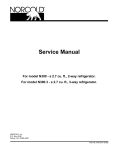
900 & 9100
Series
Service Manual & Parts List
for Models
9182 9183
9162 9163
982 983
962 963
Contents
Safety Information . . . . . . . . . . . . . . .
1
Step-by Step Trouble Shooting . . . . . . . . . 15
Introduction . . . . . . . . . . . . . . . . . . .
2
Internal Control Information - 900 Series . . . . 19
Specifications . . . . . . . . . . . . . . . . . .
3
Internal Control Information - 9100 Series . . . 24
Operating Controls . . . . . . . . . . . . . . .
5
Diagnosing Cooling Problems . . . . . . . . . . 29
Operating Sequence . . . . . . . . . . . . . .
6
Component Check-Out Procedures . . . . . . . 31
Alphanumeric Codes-900 Series . . . . . . . .
7
Procedure for Cleaning Cooling System Flue . . 33
Flashing LEDs-9100 Series(Diagnostic Indicators) . . . . . . . . . . . . .
11
Diagnostics Fault Indicators-900 & 9100 Series
13
618526C (96-05)
Fuse Replacement Procedure
. . . . . . . . . 34
Wiring Pictorials . . . . . . . . . . . . . . . . . 35
Read this manual carefully and become thoroughly acquainted with its contents before servicing this refrigerator
NOTICE: THIS APPLIANCE IS NOT APPROVED FOR USE AS A FREE-STANDING REFRIGERATOR OR
FOR MARINE APPLICATIONS. THIS APPLIANCE IS EQUIPPED FOR LP GAS AND CANNOT
BE CONVERTED TO ANY OTHER FUELS (NATURAL GAS, BUTANE, ETC.).
Be alert to a potential Safety Hazard when the Safety Alert Symbol
appears on your refrigerator or in this manual.
Also, be alert to the shaded areas in this manual; they contain important safety and performance information.
A signal word (i.e., Danger, Warning, Caution) accompanying the Safety Alert Symbol identifies the severity of the Safety
Hazard. Review the safety symbols and signal words below. Carefully read their descriptions to understand their meaning.
They are for your safety.
DANGER indicates the presence of a hazard that will cause severe personal injury, death, or substantial property
damage if ignored
WARNING indicates the presence of a hazard that can cause severe personal injury, death, or substantial property
damage if ignored.
CAUTION indicates the presence of a hazard that will or can cause a minor personal injury or substantial property
damage if ignored.
Always apply the following safety precautions when servicing this refrigerator. Failure to follow these precautions
can result in substantial property damage, severe personal injury, or death.
• Improper installation, adjustment, alteration, unauthorized or improper servicing and maintenance of this refrigerator can
cause severe personal injury, property damage, or both.
• This refrigerator must be used in the manner for which it was designed. Refer to the "Operator’s Guide" and "Installation
Requirements" manuals for refrigerator’s intended use and installation.
• Keep refrigerator and surrounding area clean. Never store combustible materials at rear of refrigerator. Storing combustible
materials at rear of refrigerator not only creates a safety hazard, but also inhibits air flow to the cooling system, reducing
cooling efficiency.
• Keep liquids away from electrical connections. Many liquids are electrically conductive and can cause arcing or fires.
• Propane gas can cause an explosion that may result in property damage, personal injury, or death. Use extreme care when
working with or near a propane gas system. Do not smoke or create sparks. Do not use an open flame to check supply piping
and fittings for leaks.
• To prevent gas leaks and damage to gas supply lines and fittings, use two wrenches when connecting or disconnecting gas
fittings.
• The 120 volt AC circuit must be properly grounded. Never cut or remove round grounding prong from refrigerator’s AC
power cord. Do not use a two-prong adapter. Do not use an extension cord.
• To prevent short circuits, connect positive DC supply lead to refrigerator before attaching ground lead.
• Always replace a blown fuse with a fuse of same ampere rating. A circuit overload can result in an electrical fire if undersized
wires or improperly sized fuses are used. To prevent a possible electrical fire, follow Norcold’s wire and fuse size specifications
and any applicable state, local, or national codes.
• Always disconnect both AC and DC power sources from refrigerator when performing routine maintenance.
• Keep liquids away from electrical connections. Many liquids are electrically conductive and can cause serious arcing
damage and fires.
• Cooling unit contents under pressure. Leaking cooling unit contents can cause severe burns to eyes and skin, and can ignite
and burn with an intense flame. The cooling unit contains sodium chromate. Inhalation of certain chromium compounds
can cause cancer. Do not attempt to repair or to recharge a defective cooling unit. Do not bend, drop, drill, weld, manipulate,
or hammer the cooling unit.
1
• This refrigerator has sharp edges and corners at the rear. Use care when working on this refrigerator. To prevent cuts or
abrasions, wear cut resistant gloves.
• Surfaces at rear of refrigerator are extremely hot. Contact with these surfaces can result in minor burns. Turn refrigerator
off for several hours before attempting to move or service refrigerator.
• To prevent child entrapment, limit access to the refrigerator and insure all wire shelf retainers are securely fastened. Always
remove the doors before disposing of any refrigerator.
Introduction
To thoroughly understand the 900/9100 series refrigerator, review "Installation Requirements" and "Operator’s Guide".
Purpose
This manual provides service information for Norcold’s 900/9100 series refrigerators. This is a service guide for the
experienced repair technician, and covers diagnostic procedures, trouble shooting, and repair procedures. It is recommended
that repair technicians be knowledgeable with the function of an absorption refrigerator and have a basic understanding of
propane and electrical systems.
Read all service procedures, cautions, and warnings before servicing refrigerator. It is critical that the refrigerator installation
is in accordance with Norcold’s recommended procedures, which are in compliance with standards for RV installations (see
"Installation Requirements" manual). The areas which are crucial to the user’s safety and refrigerator performance include
removal of the products of combustion, isolation of living space of vehicle from the combustion system of refrigerator, removal
of excess heat from the generator area of refrigerator’s cooling system, and removal of heat that is extracted from the
refrigerator cabinet (review the "Installation Requirements" manual).
Parts
Always use genuine Norcold replacement parts when servicing the refrigerator. Generic replacement parts may look similar
but do not meet Norcold quality and performance specifications. Only genuine Norcold replacement parts have been proven
to provide reliable, safe operation and performance. Order genuine replacement parts through your local Norcold parts
distributor.
Technical Support
This manual is intended to provide the repair technician with all necessary information for successful service of the
refrigerator. If after referring to this manual the problem has not been resolved, technical service is available at 1-800-5431219.
2
Specifications
MODEL
982 & 9182
983 & 9183
962 & 9162
963 & 9163
Storage Volume
cu. ft.
7.5
7.5
6.3
6.3
Cut-Out Dimensions
W x H x D
in.
23 1/2 x 59 7/8 x 24
23 1/2 x 59 7/8 x24
23 1/2 x 52 7/8 x 24
23 1/2 x 52 7/8 x 24
Certified Vent Kit
Refer to "Installation Requirements"
manual for details
Kit No. 3
Certified Installation Requires;
Vent Kit No. 3 installed without modification,
Unobstructed air flow across the refrigerator’s cooling system,
Clearances between the refrigerator and any adjacent surface
Top
0"- 1/4"
Sides
0"-1/2"
Rear
0"-1"
Bottom
0"
Venting & Installation
Door Panel Dimensions (Inches)
Upper Door H x W
Lower Door H x W
Thickness = 3/16"
14 17/32 x 21 19/32
38 5/8 x 21 19/32
14 17/32 x 21 19/32
38 5/8 x 21 19/32
14 17/32 x 21 19/32
31 5/8 x 21 19/32
14 17/32 x 21 19/32
31 5/8 x 21 19/32
Supply Voltage Requirements
DC
15.4 Max.-10.5 Min.
15.4 Max.-11.5 Min.
15.4 Max.-10.5 Min.
15.4 Max.-11.5 Min.
AC
132 Max.-108 Min.
132 Max.-108 Min.
132 Max.-108 Min.
132 Max.-108 Min.
Operating Requirements
LP Gas Operation
12 volt DC is required to operate and maintain the operating controls.
12 volts are needed to operate the interior light, moisture reduction heater, and the gas ignition
circuit. LP (Propane) Gas at supply pressure of 11" Water Column needed for LP GAS operation.
.0155 Orifice
AC Operation
.0155 Orifice
.015 Orifice
.015 Orifice
12 volt DC is required to operate and maintain the operating controls
120 volt, 60 Hertz grounded AC circuit is needed to operate the AC heater.
12 volts are needed to operate the interior light and the moisture reduction heater.
3
MODEL
DC (heater) Operation
982 & 9182
983 & 9183
962 & 9162
963 & 9163
12 VDC required to operate and maintain the operating control.
12 volts needed to operate the DC Electric (heater) and to operate the interior light and the
moisture reduction (divider) heater.
Fuses
Refrigerator Internal Fuse
DC Control Voltage
3 Amp Blade Type
AC Circuit
5 Amp 3AG (Glass)
DC Control Voltage
3 Amp Blade Type
AC Circuit
5 Amp 3AG (Glass)
DC Electric (Heater)
30 Amp Blade Type
DC Control Voltage
3 Amp Blade Type
AC Circuit
5 Amp 3AG (Glass)
DC Control Voltage
3 Amp Blade Type
AC Circuit
5 Amp 3AG (Glass)
DC Electric (Heater)
30 Amp Blade Type
DC Supply Wire Requirements
Min. Wire Size
Max. Wire Size
18 AWG
18 AWG
10 AWG
8 AWG
18 AWG
18 AWG
10 AWG
8 AWG
Min. fuse Size
Max. Fuse Size
*6 Amp
**6 Amp
*30 Amp
**40 Amp
*6 Amp
**6 Amp
*30 Amp
**40 Amp
300 /2.7 /40.3
300 /2.7 /40.3
*0-20’
**over 20’
Heater Specifications
AC Heater
Watts/Amps/Ohms
300 /2.7 /40.3
300 /2.7 /40.3
DC Heater
Watts/Amps/Ohms
225/16/.87
Ohms reading +/- 5%
Additional Current Draws
Automatic Ignition
Moisture Reduction (Divider) Heater
Interior Light
.50 amps
.11 to .17 amps
.60 amps
4
225/16/.87
Operating Controls
A 12 volt DC supply is required to maintain refrigerator’s operating control functions. The refrigerator receives its DC power
from the vehicle’s 12 volt system; either an auxiliary battery, a converter, or the engine battery. The 12 VDC system not only supplies
power to the refrigerator, but to other DC components in the vehicle.
The operating controls consist of two printed circuit board assemblies. The Control Board, located at the rear of the
refrigerator, contains the circuitry to operate the refrigerator. The Front Display Panel (located between the two doors) contains
the display area, the push-button switches, and a magnetically actuated door sensor.
900 Series Front Display Panel
C
A
E
D
Figure 1
B
A. Display Window. The control panel is equipped with a light which turns on when any button is pressed,
and remains on for 10 seconds after button is released. The display window shows temperature setting, operating
modes, and diagnostic codes
B. Temperature Settings. The temperature setting is shown in form of a thermometer in display window, with
the shortest thermometer reading indicating coldest setting.
C. Mode Button. Pressing and holding Mode button cycles through operating modes; AUTO, AC, LP GAS,
and BATT (3-Way models). The refrigerator will not switch to new operating mode until the MODE
button i s r eleased.
D. TEMP SET Button. The TEMP SET (thermostat) button controls refrigerator and freezer temperature.
Press and hold TEMP SET button to select desired temperature setting.
E. ON/OFF Button. The ON/OFF button turns refrigerator on or off. The refrigerator reverts to AUTO mode when
first turned on. To turn refrigerator OFF, press and hold button for 2 seconds.
9100 Series Front Display Panel
A
B
C
D
E
Figure 2
A. LED Indicators. The front display panel is equipped with LED indicators which illuminate to indicate the
refrigerator’s operating mode or flash when a problem exists within the operating controls.
B. Temperature Setting. The temperature setting is shown with nine (9) LED’s, with the LED furthest to the right
indicating the coldest setting,
C. Mode Button. Pressing and holding the MODE button cycles through the operating modes; AUTO, AC, LP GAS,
and BATTERY (3-Way models). The refrigerator will not switch to the new operating mode until the MODE button is
released.
D. TEMP SET Button. The TEMP SET (thermostat) button controls the refrigerator and freezer temperature. Press
and hold the TEMP SET button to select the desired temperature setting.
E. ON/OFF Button. The ON/OFF button turns the refrigerator on or off. The refrigerator reverts to the AUTO mode
when first turned on. To turn the refrigerator off, press and hold the button for 2 seconds.
5
Operating Sequence-900 and 9100 Series
Auto Mode
When AUTO mode is selected, the operating control automatically selects the energy source using the following priority
scheme:
When 120 volt AC is available, the refrigerator will operate on AC electric. If 120 volt AC is not available, the refrigerator
will switch to and operate in LP Gas mode. On 3-Way models, when neither 120 volt AC nor LP gas are available, the
refrigerator will switch to DC electric. DC electric operation is not as efficient as LP Gas or AC electric operation. DC electric
should not be used to initially cool refrigerator; it should be used only when other modes are unavailable (for example; while
in transit). If no input source (i.e 120 VAC, 12 VDC, or LP Gas) is available, the refrigerator will cease operation.
During operation in AUTO mode, when a higher priority energy source becomes available, the operating controls will cease
using the current energy source and will switch to the higher priority energy source. For example, if AC electric becomes
available while refrigerator is operating in AUTO LP GAS mode, the refrigerator will switch to AUTO AC operation. If AC
power becomes available and is found to be non functional or out of tolerance, the control will revert to the lower-priority
source.
Manual Mode
To operate in MANUAL mode, press and hold MODE button until word AUTO (900 Series) or the AUTO LED (9100
Series) disappears and desired operating mode is displayed. If energy source is interrupted while operating in MANUAL
mode, the corresponding fault indicator will appear, and refrigerator will cease operation until an alternate energy source is
selected or the problem is corrected.
AUTO and MANUAL Modes - Gas Operation Only
If gas does not ignite within 30 seconds, which may occur on initial start-up, the refrigerator’s gas valve will automatically
close and the operating controls will select an alternate energy source ( AUTO Mode) or, MANUAL mode, will revert to a
stand-by mode in which a fault indicator will appear. The fault indicator will remain until operating controls are turned OFF
and then ON again. If gas does not ignite after several attempts, refer to "Diagnostic" and "Trouble Shooting" sections for
corrective actions. A different mode of operation may be selected by pressing and holding MODE button. The refrigerator
will not switch to new operating mode until the MODE button is released.
LP GAS Mode Operation
When operating in LP Gas mode, the control opens the gas valve and sends a spark to the burner to ignite flame. The ignition
cycle is carried out as follows.
1. The gas valve is opened and spark output is activated for 1 second.
2. The spark output is de-activated and flame sense circuit is monitored. If there is no flame 1 second later,
spark output is re-activated.
3. Steps 1 and 2 are repeated until 30 seconds have elapsed, or until a flame is sensed during Step 2.
If burner fails to ignite, the control will turn off gas valve, lock out LP GAS mode, and display appropriate fault code. With
3-Way models operating in AUTO LP GAS mode, the control will automatically switch to DC Electric (heater) mode. While
operating in DC Electric mode, the appropriate fault indicator will be displayed. If DC voltage is available to refrigerator but
is below specification, the appropriate fault indicator will be displayed.
If the flame goes out, the control attempts to re-ignite flame, beginning with a new 30 second ignition trial. There is no limit
to the number of times flame can be lost and re-ignited.
If the control is displaying a fault indicator, pressing MODE button will disable the indicator and re-initiate 30 second trial
for ignition. During 30 the second time interval, an alternate mode of operation can be selected by pressing the MODE button.
When control measures input voltage below 10.5 VDC, gas operation is locked out.
Back-Up Operating System (BOS)
The refrigerator’s operating controls feature a Back-Up Operating System which provides a means for the refrigerator to
cool in the event of a temperature sensor failure. Once the BOS mode is entered, the temperature sensor is ignored and the
control displays a fault indicator. This mode provides adjustable cooling until the refrigerator is serviced. Norcold recommends
the refrigerator owner seek service as soon as practical to restore normal operation.
6
Description of Alphanumeric Codes for 900 Series (Diagnostic Indicators)
The refrigerator’s operating control is equipped with Alphanumeric Codes which assist the service technician in trouble
shooting and alert the refrigerator owner to a problem in any mode of operation. When a problem occurs within a given mode, the
operating controls will revert to a stand-by mode in which an alarm will sound and a two digit alphanumeric code will be displayed in
the center control window. The alarm will sound until an alternate operating mode is selected. The alphanumeric code will continue
to be displayed until the controls are turned off and then back on or until the problem is corrected. Diagnostic codes which begin
with A indicate a minor problem that may usually be corrected by the refrigerator owner. Diagnostic codes beginning with C or D
indicate faults which are not owner serviceable but instead require service from a qualified service technician. Codes and their
meanings begin below.
A1-LP Gas Ignition Failure-Initial Refrigerator Start-Up
Burner ignition failure on initial start-up can occur whenever the refrigerator is started after each shut-down period.
AUTO MODE - 2-Way Models
Alarm, flashing backlight and bell will be
active.
AUTO MODE - 3-Way Models
No alarm, flashing backlight or bell.
Operating controls switch to and operate in the
BATT (DC Heater) mode
MANUAL MODE - 2-Way Model
Alarm, flashing backlight and bell will be
active.
Controls will not switch to another energy
source. Refrigerator will cease operation.
MANUAL MODE - 3-Way Model
Alarm, flashing backlight and bell will be active.
Controls will not switch to another energy
source. Refrigerator will cease operation.
A2-LP Gas Re-Ignition Failure-During Normal gas Operation
A2 code will appear when the gas fails to re-ignite during a cycle period.
AUTO MODE - 2-Way Models
Alarm, flashing backlight and bell will be
active.
AUTO MODE - 3-Way Models
No alarm, flashing backlight or bell.
Operating controls switch to and operate in the
BATT (DC Heater) mode
MANUAL MODE - 2-Way Model
Alarm, flashing backlight and bell will be
active.
Controls will not switch to another energy
source. Refrigerator will cease operation.
MANUAL MODE - 3-Way Model
Alarm, flashing backlight and bell will be active.
Controls will not switch to another energy
source. Refrigerator will cease operation.
A3-Fresh Food Compartment Door Ajar
If the fresh food compartment door is left open for more than two minutes, the refrigerator control turns off the light,sounds
an alarm, and displays the A3 code to the alert the owner that the door is ajar.
AUTO and MANUAL MODE-2 & 3-Way Models
Alarm, flashing backlight and bell will be active. Operation will not be interrupted.
A4-AC Mode Selected, AC Power Not Available
AUTO MODE-2 & 3-Way Models
No code, alarm, flashing backlight or bell. Operating controls will switch to and operate in the next
available energy source.
MANUAL MODE-2 & 3-Way Models
Alarm, flashing backlight and bell active. Controls will not switch to another energy source.
Refrigerator will cease operation.
7
A5-AC Input Voltage Too Low
AUTO MODE-2 & 3 Way Models
No code, alarm, flashing backlight or bell. Operating controls will switch to and operate in the next
available energy source.
MANUAL MODE-2 & 3-Way Models
Alarm, flashing backlight and bell active. Controls will not switch to another energy source.
Refrigerator will cease operation.
A6-AC Input Voltage Too High
AUTO MODE-3 & 3-Way Models
No code, alarm, flashing backlight or bell. Operating controls will switch to and operate in the next
available energy source
.MANUAL MODE-2 & 3-Way Models
Alarm, flashing backlight and bell active. Controls will not switch to next energy source.
Refrigerator will cease operation.
A7-DC Input Voltage Too Low
When the voltage range is below the specifications, the control will lock-out and will not allow operation on "LP GAS"
or power the "BATT" (DC Heater) operation.
AUTO MODE-2 & 3-Way Models
Alarm, flashing backlight and bell active. Operating controls will not switch to next energy source.
Refrigerator will cease operation.
MANUAL MODE-2 & 3-Way Models
Alarm, flashing backlight and bell active. Operating controls will not switch to next energy source.
Refrigerator will cease operation.
A8-DC Input Voltage Too High
AUTO MODE-2 & 3 Way Models
No alarm, flashing backlight or bell. Code will remain on until DC input voltage corrected.
Refrigerator will operate.
MANUAL MODE-2 & 3-Way Models
No alarm, flashing backlight or bell. Code will remain on until DC input voltage corrected.
Refrigerator will operate
C1-Burner Failed Ignition and DC Heater Failed-3 Way Models Only (AUTO Mode)
In AUTO mode, if there is a burner ignition failure (Codes A1 0r A2), the control will attempt to select BATT (DC heater).
If DC heater is open, the C1 failure occurs.
3-Way Models Only
Alarm, flashing backlight and bell active. Fault code, alarm, flashing backlight and bell remain on
until the problem is corrected and the controls are reset.
8
C2-AC Heater Output Fault
The control senses AC heater current when the AC heater should be "OFF".
AUTO MODE-2 & 3 Way Models
Alarm, flashing backlight and bell active. Controls will not select an alternate energy source.
Controls will lock out all modes of operation until AC is disconnected from refrigerator or problem
is corrected. Disconnecting AC power source to refrigerator will allow refrigerator to switch to and
operate in the LP GAS mode.
MANUAL MODE-2 & 3 Way Models
Alarm, flashing backlight and bell will be active. Controls will lock out all modes of operation until
AC is disconnected or the problem is corrected. Refrigerator can be manually switched to operate
in the LP GAS mode.
C3-DC Heater Output Fault 3-Way Models Only
The control senses DC heater current when the DC heater should be "OFF".
AUTO MODE 3-Way Models Only
Alarm, flashing backlight and bell active. Refrigerator will cease operation. Control will not select
an alternate energy source. Control will lock-out all operating modes. Switch and operate the
refrigerator in the manual mode until problem is corrected.
MANUAL MODE 3-Way Models Only
Alarm, flashing backlight and bell will be active. Refrigerator will cease operation until problem
corrected. Refrigerator can be manually switched and operated in either the AC electric or LP Gas
mode.
C4-3-Way Models Only-DC Heater Failed Open
DC voltage is being supplied to the heater but the heater is not drawing current (no cooling).
AUTO MODE 3-Way Models Only
Alarm, flashing backlight and bell will be active. Controls will not switch to or operate in the next
available energy source. Refrigerator will cease operation. Fault code will remain on until the
problem is corrected and the controls are reset.
MANUAL MODE 3-Way Models Only
Alarm, flashing backlight and bell will be active.
Controls will not select the next available energy source.
Refrigerator will cease operation until problem is corrected. Fault code will remain on until the
problem is corrected and the controls are reset.
C5-Back-Up Operating System
If the thermistor becomes inoperable, the power board will revert to the Back-Up Operating System. When the refrigerator
enters this mode the thermistor is ignored and the refrigerator will interpret the thermostat setting as a duty cycle command.
AUTO MODE 2 & 3 WAY Models
No Alarm, flashing backlight or bell. Operating controls will switch to and operate in the "Back-Up
Operating System". Fault code will remain until corrected and controls reset.
MANUAL MODE 2 & 3 Way Models
No alarm, flashing backlight or bell. Operating controls will operate in the "Back-Up Operating
System". Fault code will remain until corrected and the controls are reset.
9
C6-AC Heater Failed Open
AC voltage supplied to heater; AC heater not drawing current.
AUTO MODE-2 & 3 Way Models
No alarm, flashing backlight, or bell. Operating controls will switch to and operate in the next
available energy source.
MANUAL MODE-2 & 3 Way Models
Alarm, flashing backlight, and bell will be active. Controls will not switch to next available energy
source. Refrigerator will cease operation until another energy source is manually selected.
C7-Flame Sense Circuit Failure
AUTO MODE-2 & 3 Way Models
No alarm, flashing backlight or bell. Operating controls will switch to and operate in the next
available energy source.
MANUAL MODE-2 & 3 Way Models
Alarm, flashing backlight and bell will be active. Controls will not switch to the next available
energy source.
Refrigerator will cease operation until another energy source is manually selected.
C8-AC Heater Failed for Current Out-of-Tolerance
AUTO MODE- 2 & 3 Way Models
No alarm, flashing backlight or bell will be active. Operating controls will not switch to or operate in
another energy source.
MANUAL MODE-2 & 3 Way Models
Alarm,flashing backlight and bell will be active. Operating controls will not switch to the next
available energy source. Refrigerator will cease operation.
C9-DC Heater Failed for Current-Out-Tolerance-3 Way Models
AUTO MODE
No alarm, flashing backlight or bell will be active. Operating controls will not switch to or operate in
another energy source. Fault code will remain on until problem is corrected and the control is
reset.
MANUAL MODE
Alarm, flashing backlight and bell will be active. Operating controls will not switch to the next
available energy source. Refrigerator will cease operation until problem is corrected or another
energy source is selected.
d1-Inter Control Failure
AUTO & MANUAL MODES
This is a fault within the control board
10
Description of 9100 Series Flashing LED’s (Diagnostic Indicators)
The LEDs on the front display panel flash if a fault occurs within the operating controls. The flashing LEDs assist the service
technician in trouble shooting and alert the refrigerator owner to a problem in any mode of operation. When a problem occurs
within a given mode, the operating controls revert to a stand-by mode in which an LED or series of LEDs begin flashing. The
LED or LEDs continue flashing until either the control is turned Off and then back On or the problem is corrected. Flashing
LED’s and their meanings begin below.
Flashing LP Gas LED-All Models
(LED will flash, pause, flash, pause, etc.)
Burner ignition failure on initial start-up or gas re-ignition during a cycle period.
Flashing AC LED-All Models
(LED will flash, pause, flash, pause, etc.)
Fault external to refrigerator controls. AC mode selected, AC power not available.
Flashing AC LED-All Models
(LED will flash, flash, pause, flash, flash, pause, etc.)
Fault external to refrigerator controls. AC input voltage either too high or too low.
Flashing Battery LED-All Models
(LED will flash, flash, pause, flash, flash, pause, etc.)
Fault external to refrigerator controls. DC input voltage either too high or too low.
All LED’s Flashing-3 Way Models Only
All LED’s will flash, pause, flash, pause, etc.)
In the AUTO mode, the burner failed ignition and DC heater failed.
All LED’s Flashing-All Models
(The LED will flash, pause, flash, pause, etc.)
AC heater output fault. The control senses AC heater current when the AC heater
should be OFF.
All LED’s Flashing-3 Way Models Only
(The LED’s will flash, pause, flash, pause, etc.)
DC heater output fault. The control senses DC heater current when the DC heater
should be OFF.
11
All LED’s Flashing-3 Way Models Only
(LED’s will flash, pause, flash, pause, etc.)
DC heater failed open. DC voltage is being supplied to the heater but the heater is not
drawing current (no cooling).
Flashing Temperature Setting LED-All Models (LED will flash, pause, flash, pause, etc.)
Back-Up Operating System. If the thermistor becomes inoperable, the power board will
revert to the Back-Up Operating System. When the refrigerator enters this mode the
thermistor is ignored and the refrigerator will interpret the thermostat setting as a duty
cycle command.
All LED’s Flashing-All Models
(LED’s will flash, pause, flash, pause, etc.)
AC heater failed open. AC voltage supplied to heater; AC heater not drawing current.
All LED’s Flashing-All Models
(LED’s will flash, pause, flash, pause, etc.)
Flame sense circuit failure.
All LED’s Flashing-All Models
(LED’s will flash, pause, flash, pause, etc.)
AC heater failed for current out-of-tolerance.
All LED’s Flashing-3-Way Models Only
(LED’s will flash, pause, flash, pause, etc.)
DC heater failed for current out-of-tolerance.
12
900 & 9100 Series Diagnostic Fault Indicators & Corrective Actions
The following table is designed to show the commonalty between the fault indicators of the 900 and the 9100 Series. The
corrective actions on the following pages are designed
900 Series
Code
9100 Series
LED
Meanings
Corrective Action
No Illumination of
Display Panel
No LED’s
Control voltage unavailable to display
panel
See Section 1 on page 15
A1
Flashing LP Gas
Indicator
(flash, pause,
flash, pause, etc.)
LP Gas Ignition Fault
See Section 2 on page 16
A2
Flashing LP Gas
Indicator
(flash, pause,
flash, pause, etc.)
LP Gas Ignition Fault
(During Normal Operation)
See Section 2 on Page 16
A3
Not Applicable
Door ajar and interior light on for more
than 2 minutes.
See Section 3 on Page 16
A4
Flashing AC LED
(flash, pause,
flash, pause, etc.)
Fault external to refrigerator controls
AC mode selected, AC power not
available
See Section 4 on Page 16
A5
Flashing AC LED
(flash, flash,
pause, flash, flash,
pause, etc.)
Fault external to refrigerator controls
AC input voltage too low
See Section 5 on Page 17
A6
Flashing AC LED
(flash flash, pause,
flash flash, pause,
etc.)
Fault external to refrigerator controls
AC input voltage too high
See Section 6 on Page 17
A7
Flashing Battery
LED (flash flash
pause, flash flash
pause, etc.)
Fault external to refrigerator controls
DC input voltage too low
See Section 7 on Page 17
A8
Flashing Battery
LED (flash flash
pause, flash flash
pause, etc.)
Fault external to refrigerator controls
DC input voltage too high
See Section 8 on Page 17
C1
All LED Flashing
(flash, pause,
flash, pause, etc.)
Burner failed ignition and DC heater failed
3- way models only
See Section 9 on Page 17
C2
All LED Flashing
(flash, pause,flash,
pause, etc.)
AC Heater fault
See Section 10 on Page 17
C3
All LED Flashing
(flash, pause,flash,
pause, etc.)
DC heater output fault- 3-Way Models
See Section 11 on Page 17
13
900 Series
Code
9100 Series
LED
Meanings
Corrective Action
C4
All LED Flashing
(flash, pause,flash,
pause, etc.)
3-Way Models Only - DC Heater Failed
(voltage but no current)
See Section 12 on page 18
C5
Current TEMP
SET LED Flashing
(flash, pause,
flash, pause, etc.)
Back-Up Operating System
See Section 13 on Page 18
C6
All LED Flashing
(flash, pause,flash,
pause, etc.)
AC Heater Failed Open
See Section 14 on Page 18
C7
All LED Flashing
(flash, pause,flash,
pause, etc.)
Flame Circuit Failure
See Section 15 on Page 18
C8
Not applicable
AC Heater Failed - Current out of
Tolerance
See Section 16 on Page 18
C9
Flashing Battery
LED (flash flash
flash, pause, flash
flash flash, pause,
etc)
DC Heater Failed - Current out of
Tolerance- 3 WAY Models Only
See Section 17 on Page 18
d1
Not Applicable
Internal Control Failure
See Section 18 on page 19
14
900 and 9100 Series Step-by-Step Trouble Shooting by Diagnostic Fault Indicators
This section is intended to serve as a check list to aid the repair technician in solving a problem. Look at the fault indicator
(Diagnostic Fault Indicators and Corrective Actions on page 13) and its meaning, then follow the guide to correct the problem.
Wire Harness
connection.
Section 1 - No Display on Display Panel
3 Amp control
voltage fuse
5 Amp Fuse
Corrective Action
1.
Battery charging equipment or converter.
2.
Input DC supply voltage to the refrigerator’s
control board. Correct if DC Voltage is below 10.5
VDC.
3.
12 VDC supply wire connections to the control board.
Correct if loose.
4.
Remove the control board cover and check the 3 Amp
control voltage fuse. Replace if defective.
5.
If the 3 amp fuse blows after replacement, insure the
interior light cover is installed correctly. If the 3 amp
fuse continues to blow, disconnect the light wires from
the light bracket. Start refrigerator. If fuse does not
blow, replace light bracket. If fuse blows, replace control board.
30 Amp DC
Heater Fuse
12 VDC
Supply Wires
Figure 3
Top of Connector
Caution: A circuit overload can result in an
electrical fire when incorrect size fuses are
used. To prevent a possible electrical fire,
replace a blown fuse with the exact replacement. Refer to "Specifications" chart on page
4 for correct fuse size and type.
Wire Harness
6.
Check wire harness connection to control board. Secure
connection if needed.
7.
At front of refrigerator, remove front display panel to
gain access to wire harness connection.
A
8.
Inspect pins of the wire harness. Insure they are seated
within the connector.
B
9.
Check for 12 VDC between points A and B (Figure 4).
10.
If 12 VDC is present, replace front display panel. If 12
VDC is not present, replace power board.
15
Figure 4
Section 2 - LP Gas Ignition Failure - Initial Refrigerator Start-Up & LP Gas Re-Ignition
Failure - During Normal Gas Operation
Corrective Action
1. Has LP gas tank been filled recently? Purge gas line to refrigerator.
2. Is LP gas tank valve on? Turn valve on.
3. Is refrigerator’s manual shut-off valve on? Turn manual valve on.
4. Is LP Gas supply pressure to the refrigerator at 11" water column?
5. Check input DC supply voltage to refrigerator’s power board. Correct if DC voltage below 10.5 VDC or a bove 15.4 VDC
6. Secure ignition wire connection at power board if necessary.
7. Secure wire connections from power board to gas valve if necessary.
8. If ignition wire is damaged, replace ignition/sense electrode assembly
9. Does the sense/electrode wire have continuity? Replace if no continuity found.
10. Check the sense/ignition wire for short to ground. Any reading, replace sense/ignition wire.
11. Measure DC voltage across the terminals of the gas valve during the trial for ignition. If the voltage is between
10.5 to 15.4 VDC and an audible click is not heard from the valve during trial for ignition, replace the gas valve.
If the DC voltage is not being supplied to the gas valve, replace the power board.
12. Inspect the burner flame to verify that it has a sharp blue and stable appearance. If there is a constant yellow component
observed or if the flame appears erratic or unstable (roaring), the burner, orifice, and the cooling unit’s flue must be
cleaned.
13. Check the alignment of the electrode for the correct spark gap. The electrode tip is to be positioned between 1/8" - 3/16"
from the top of the burner.
Section 3 - Fresh Food Compartment Door Ajar
Corrective Action
1. Close the door to turn off the alarm, flashing backlight and bell, and to remove code.
2. If the light is on with door closed, use a magnetic screwdriver and move it diagonally across the
bottom of the Control Box Assembly.
3. If the code disappears, alarm ceases, and the flashing backlight and bell ceases, the magnet in the
door is defective. Replace lower door.
4. If the code remains, the alarm sounds and the flashing backlight and bell remain active, replace
the Control Box Assembly.
Section 4 - AC Mode Selected, AC Power Not Available
Corrective Actions
1. Check vehicle AC fuse or circuit breaker. Replace fuse if blown or reset circuit breaker if tripped.
2. Check input AC supply voltage to receptacle into which refrigerator is plugged. Correct power source to
receptacle. AC voltage must be between 108 VAC min.-132 VAC max.
3. Check input AC supply voltage to refrigerator’s power board. Disconnect AC power cord from power board.
Measure AC voltage at the terminal end of the AC power cord. If AC voltage not available, replace
power cord
4. Insure AC fuse holder compresses fuse. Tighten fuse holder clips if necessary.
5. Check refrigerator’s AC fuse (5 Amp). Replace if blown.
16
Section 5 - AC Input Voltage too Low (See Internal Control Information)
Corrective Actions
Check input AC supply voltage to refrigerator. Correct input AC voltage (108 VAC 132 VAC max.).
Section 6 - AC Input Voltage too High (See Internal Control Information)
Corrective Actions
Check input AC supply voltage to refrigerator. Correct input AC voltage (108 VAC 132 VAC max.).
Screen 7 - DC Input Voltage too Low (See Internal Control Information)
Corrective Actions
1. Check input DC supply voltage to refrigerator. Correct input DC voltage(10.5 VDC min.)
2. Check DC supply wire connections at power board. Secure connections if loose.
3. Check vehicle’s battery charging equipment. Correct charging equipment.
Section 8 - DC Input Voltage too High (See Internal Control Information)
Corrective Actions
1. Check input DC supply voltage to refrigerator. Maximum input DC voltage is 15.4 VDC.
2. Check vehicle’s battery charging equipment. Correct equipment.
Section 9 - Burner Failed Ignition and DC Heater Failed - 3 Way Models Only
Corrective Action
Correct input DC supply voltage (10.5 VDC min. - 15.4 VDC max.).
Section 10 - AC Heater Output Fault
The control senses AC heater current when the AC heater should be OFF.
Corrective Action
Replace power board
Section 11 - DC Heater Output Fault - 3 Way Models Only
The control senses DC heater current when the DC heater should be OFF.
Corrective Action
Replace power board
17
Section 12 - 3 Way Models Only - DC Heater Failed Open
Corrective Action
1. Measure the resistance through the DC heater. An open heater reads infinity and requires replacement.
2. Check all wire connections. If wire connections are secure and DC heater is not found open, replace power board.
Section 13 - Back-Up Operating System
If the thermistor becomes inoperable, the power board will revert to the Back-Up Operating System. When the refrigerator
enters this mode the thermistor is ignored and the refrigerator interprets the thermostat setting as a duty command.
Corrective Action
Replace Lamp/Thermistor Wire Assembly
Section 14 - AC Heater Failed Open
AC voltage being supplied to AC heater but the heater is not drawing current.
Corrective Action
1.Measure the resistance through the AC heater. An open heater reads infinity and requires replacement.
2. If AC heater is not found open, replace power board.
Section 15 - Flame Sense Circuit Failure
Corrective Action
1. Check for cracks or breaks in the sense/ignition wire. Replace when cracks or breaks are found.
2. Check alignment of electrode. Adjust to 1/8" to 3/16 " from top of burner.
2. Check the sense/electrode wire for continuity. Replace if no continuity found.
3. Check the sense/ignition wire for short to ground. Any reading, replace sense/ignition wire.
4. Check ignition wire connection at power board. Secure connection if loose.
5. Replace power board.
Section 16 - AC Heater Failed for Current Out of Tolerance
Corrective Action.
Check AC heater for correct wattage (300 Watt) and measure resistance of the heater. The heater is to measure between
38.3 and 42.3 Ohms. Replace if resistance is not within specifications.
Section 17 - DC Heater Failed for Current Out of Tolerance
Corrective Action.
Check DC heater for correct wattage (225 Watt) and measure resistance of the heater (page 31). The heater is to measure
between .83 and .91 Ohms. Replace if resistance is incorrect.
18
Section 18 - Internal Control Failure
Corrective Action
Replace power board.
Internal Control Information - 900 and 9100 Series
Internal Control Information provides additional information to aid in trouble shooting. To access the Internal Control
Information mode (900 and 9100 series), press the TEMP SET and the MODE buttons simultaneously for 10 seconds. While
in the Internal Control Information mode, the refrigerator continues to operate in the mode selected prior to entering the
information mode. Different control information displays can be selected with the MODE button. The 900 series control
illuminates images on the display panel. The 9100 series internal information is communicated through the 9 temperature
LED’s. The Internal Control Information mode can be exited by pressing the MODE and TEMP SET buttons simultaneously
for 2 seconds, after which the control reverts to the normal display mode.
900 Series Informational Screens
Screen No. 1 - Input Images
A
B
C
Figure 5
A. Identifies the information screen.
B. When operating in the LP Gas mode, this bar signifies burner flame is sensed by the power board.
C. All modes of operation. This bar signifies that the door switch is in the closed (normal) position, that the fresh food
compartment door is closed, and that the interior light is OFF.
19
Screen No. 2 - Output Images
On this screen, the refrigerator control illuminates images corresponding to output it is energizing. These images are intended
to aid in trouble shooting when the images are compared against the actual control output voltages.
H
A
B
C
D
E
F
G
Figure 6
A. Identifies information screen.
B. When operating in the "BATT" mode, when this bar is illuminated, it signifies the power board is supplying
DC voltage to the DC heater.
C. All modes of operation. When this bar is illuminated, it signifies the power board is supplying DC
voltage to the moisture reduction (divider) heater.
D. When operating in the "LP GAS" mode, when this bar is illuminated, it signifies the power board
is providing ignition spark to the burner.
E. When operating in the "AC" Electric mode, when this bar is illuminated, it signifies the power board
is supplying AC voltage to the AC heater.
F. When operating in the "LP GAS" mode, when AC is illuminated, it signifies that the power board
is supplying DC voltage to the gas valve.
G. All modes of operation. When "BATT" is illuminated, it signifies that the power board is supplying
DC voltage to activate the alarm and backlight
H. All modes of operation. When "LP GAS" is illuminated, it signifies the power board is supplying DC
voltage to activate the interior light.
20
Screen No. 3
On this screen, the refrigerator control illuminates an image which is a real time indication of control activity.
I
J
A
B
C
D
Figure 7
E
F
G
H
A. Identifies information screen.
B. All modes of operation. When this bar is illuminated, it signifies that the controls are calling for cooling.
C. When operating in the "AC" electric mode, when this bar is illuminated, it signifies that AC voltage
is present and within specifications (108 VAC min.-132 VAC max.)
D. All modes of operation. When illuminated, this bar signifies that the fresh food compartment door
has been opened for more than 2 minutes.
E. All modes of operation. When illuminated, this bar signifies that the control’s temperature sensing
circuit is satisfied and not calling for cooling.
F. When operating in the "LP GAS" mode, when this bar is illuminated, it bar signifies that a flame is present at the burner.
G. When "AC" is illuminated, the current operating mode is AC electric
H. When "BATT" is Illuminated, the current operating mode is BATT (DC electric)
I. When "LP GAS" is illuminated, the current operating mode is LP GAS.
J. When "AUTO" is illuminate, the current operating mode is AUTO.
21
Screen No.4 - Fin Temperature Sensed by the Thermistor
The Thermistor is mounted on the 11th (from the right) cooling fin and monitors the refrigerator cabinet temperature
A
B
Figure 8
A. Identifies information screen
B. Cooling Fin Temperature (° F).
The following procedure verifies the thermistor is functioning:
1. Remove the thermistor from the fin and immerse thermistor end in ice water. The temperature
displayed on Screen No. 4 should be between 29 ° F and 35° F.
2. Remove the thermistor from the ice water and hold thermistor end in hand. The temperature
displayed on Screen No. 4 should rise.
3. If the temperature does not fall and rise when performing steps 1 and 2, replace the thermistor.
Screen No. 5 AC Electric Input Voltage
This screen displays AC input voltage measured by the control.
A
C
B
Figure 9
A. Identifies information screen.
B. The refrigerator control displays AC input voltage measured by the control over the range of 108
132 VAC.
C. Indicates AC electric mode of operation.
To verify:
1. Measure the input voltage at the receptacle supplying the AC voltage to the refrigerator. The voltage
should be +/- 10 VAC of the control’s display.
2. Measure the output voltage of the control board to the AC heater. The voltage should equal the
input voltage measured in Step 1.
22
Screen No. 6 AC Heater Current
This screen displays AC current measured by the control (decimal point implied).
A
C
B
Figure 10
A. Identifies information screen.
B. The refrigerator control displays AC current measured by the control. Figure 10 indicates 2.9 amps.
C. Indicates AC electric mode of operation.
To verify:
1. Measure the AC current draw through the AC heater (2.7 - 2.9 Amps). The current will be +/- 10%
of the control’s display.
Screen No.7-DC Input Voltage
This screen displays the measured DC (decimal point is implied) input voltage to the control.
C
A
B
Figure 11
A. Identifies information screen.
B. The refrigerator control displays the DC input voltage measured by the control over the range of 10.5 to 15.4 VDC. (Figure 11
indicates 12 VDC).
C. BATT will be displayed indicating DC voltage.
To verify:
1. Measure the input DC voltage at the control board. The voltage will be +/- 1.0 VDC of the control’s
display.
23
Screen No.8 - 3-Way Models Only DC Heater Current
This screen displays the measured DC heater current (decimal point is implied).
C
A
B
Figure 12
A. Identifies information screen.
B. The control displays the current through the DC heater measured by the control over a range of 9 to 21 amperes. (Figure 12
indicates 16 amps).
C. Indicates BATT (DC heater) mode of operation.
To verify:
Measure DC current through the DC heater. The current will be +/- 10% of the control’s display.
Internal Control Information-9100 Series
Screen No. 1 - Input and Output
A - Identifies information screen.
1 - Not Applicable
2 - Not Applicable
3 - All modes of operation. LED on signifies the fresh
food compartment door is closed and the interior light
is off.
4 - LP GAS mode, LED on signifies a burner flame
present at the burner.
5 - AC electric mode, LED on signifies that the power
board is supplying AC voltage to power the AC heater.
6 - BATTERY mode, LED on signifies the power
board is supplying DC voltage to power the DC heater.
7 - All modes of operation, LED on signifies the
power board is supplying DC voltage to power the
moisture reduction (divider) heater.
8 - LP GAS mode, LED on signifies the power board
is supplying power to the gas valve.
9 - All modes of operation, LED on signifies the
power board is supplying DC voltage to activate the
interior light.
Screen No. 2
24
On this screen, the refrigerator control illuminates
LED’s which are real time indication of control activity.
A - Identifies information screen.
1 - Not Applicable
2 - Not Applicable
3 - Not Applicable
4 - ALL modes of operation, LED on signifies that
the control temperature sensing circuit is not satisfied
and is calling for cooling.
5 - AC Electric mode, LED on signifies that AC
voltage is present to AC heater and within specifications (108 VAC min. - 132 VAC max.).
6 - LED on signifies current operating mode is AUTO.
7 - LED on signifies current operating mode is AC
electric.
8 - LED on signifies current operating mode is LP
GAS.
9 - LED on signifies current operating mode is BATTERY (DC electric).
Screen No. 3 - Fin Temperature
Sensed by Thermistor
The thermistor is mounted on the 11th cooling fin
from the right and monitors the refrigerator cabinet
temperature.
A - Identifies information screen.
B - The temperature will be displayed in °F on the 9
LED TEMP SET display as shown in Figure 15. Each
LED is assigned a number. To determine cooling fin
temperature, add numbers above illuminated LED for
fin temperature.
Shown: 32 +2+1= 35°F.
The following verifies thermistor functionality:
1 - Remove thermistor from fin and immerse thermistor end in ice water. The numerical result (temperature) should be between 29° F and 35° F.
2 - Remove thermistor end from ice water and hold in
hand. The temperature should rise.
If temperature does not fall or rise when performing
the steps above, replace thermistor.
25
Screen No. 4 - AC Electric Input Voltage
This screen displays AC input voltage measured by
control.
A - Identifies information screen.
B -The control will display the AC input voltage to refrigerator. Each LED is assigned a
number. To determine AC input voltage, add
numbers above illuminated LED for voltage.
Shown: 64+32+16+8=120 VAC
To verify:
1 - Measure input voltage at receptacle supplying AC voltage to refrigerator. Voltage should
be +/- 10 VAC of control display.
2 - Measure output voltage of the control board
to AC heater. Voltage should equal input voltage measured in Step 1.
Screen No. 5 - AC Heater Current
This screen displays AC current measured by the
control (decimal point implied).
A - Identifies information screen.
B - The control will display the AC heater
current measured by control. Each LED is assigned a number. To determine current of AC
heater, add numbers above illuminated LED.
Shown: 16+8+4+1=29 or 2.9 amps
(decimal point implied)
To verify:
1 - Measure AC current draw through AC
heater (2.7-2.9 amps). The current will be +/10% of the control display.
26
Screen No. 6 - DC Input Voltage
This screen displays the DC input voltage as measured by the control.
A - Identifies Information screen.
B - The control displays the DC input voltage to
refrigerator. Each LED is assigned a number. To
determine DC input voltage, add numbers above illuminated LED for voltage.
Shown: 8+4=12
To verify:
Measure the input DC voltage at control board. The
voltage will be +/- 1.0 VDC of the control’s display.
Screen No. 7 - DC Heater Current
(3-Way Models Only)
This screen displays DC heater current measured by
the control.
A - Identifies information screen.
B - The control displays the measured DC current.
Each LED is assigned a number. To determine DC
current, add numbers above illuminated LED.
Shown: 16=16 amps
To verify:
Measure the DC current through DC heater. The current should be +/- 10% of the control’s display.
27
Screen No. 8
This screen verifies that the control is able to turn the
LED’s off. If any LED remains on, replace power
board.
Screen No. 9
This screen verifies that all LEDs are functioning. If
any LED fails to light, replace either the display panel
or the power board. See Section 1 on page 13 to
determine which part requires replacing.
28
Diagnosing Cooling Problems
Note: If the refrigerator operates on one heat source but not another, the problem is not the cooling
system. Before continuing with this procedure, refer to the diagnostic section. Diagnose the cooling
system only when the refrigerator does not cool or cools marginally on both the AC electric and
LP Gas modes.
Make Certain the refrigerator owner understands:
• Unlike a home refrigerator, an RV refrigerator requires the foods to be pre-cooled; frozen foods should be pre-frozen before
loading the refrigerator. Loading a warm refrigerator with warm food increases the cool down time. Turn the refrigerator
on for several hours before loading.
• For best cooling performance, air must be free to circulate within the fresh food compartment. Do not cover the shelves
with paper, plastic, etc.
• Reduce frost formation, cover liquids and moist foods. Do not place hot foods in the refrigerator, and do not leave the door
open longer than necessary.
• Periodically inspect the ventilation system. Remove obstructions such as bird and squirrel nests, etc.
• Do not use the intake vent area for storage. Storing items will block the air flow needed for cooling performance.
• Place ice cube trays flat on bottom surface of the freezer to make ice.
Off Level Condition
WARNING
Operating refrigerator outside of the cooling system specification of 3 degrees off level side-to-side
and 6 degrees off level front-to-back can cause irreparable damage to cooling system and can
create a risk for personal injury or property damage. Level vehicle before operating refrigerator.
Insure that refrigerator is operating within cooling systems specifications of 3 degrees off level side-to-side and 6 degrees
off level front-to-back. The vehicle may be level but refrigerator may not be because of improper installation.
Good Installation/Ventilation
1
6
2
3
Installation/Ventilation
Extremely hot days ( 90 ° or higher) can lead to warmer temperatures in both the freezer and fresh food compartments, especially
when air flow across cooling system is restricted. Make sure
refrigerator is installed in accordance with Norcold’s installation
requirements. Refer to Figure 22, the statements below, and
"Installation Requirements" manual (provided with each refrigerator).
1. Exhaust vent centered directly over the condenser of refrigerator.
2. Baffle added at top of refrigerator to assist in directing air flow
out exhaust vent. 0-1/4" minimum clearance at top of refrigerator.
3. Unrestricted air flow from intake vent to refrigerator absorber
coils and from refrigerator absorber coils through condenser and
out exhaust vent.
4. 1" maximum clearance at rear of refrigerator.
5. Intake vent installed flush with surface on which the refrigerator
is mounted.
5
4
Figure 22
6. 1/2" maximum clearance between the vehicle walls and sides
of the refrigerator.
29
Inputs:
Make certain that:
• The AC and DC voltages and the LP Gas supply pressure are within the required specifications. Refer to "Specification"
charts on pages 3 and 4.
Checking Door Seals
The door gaskets must seal completely around the entire length of
the door. Frequent frost formation or reduced cooling can be indications of air leaks.
Pull paper away from
refrigerator
To check for proper door seal, lay a long narrow strip of paper
between the gasket and the refrigerator. Close the door and withdraw
the paper. A frictional drag should be observed. Repeat all around
the doors. If the paper does not have a noticeable drag, the gasket is
not sealing.
Strip of paper
Figure 23
Refrigerant Charge Solution
WARNING
Corrosive liquid. Eye or skin contact can cause severe burns. Contents under pressure. Leaking
gas can ignite and burn with intense flame. Leaking coolant solution can cause severe burns to the
eyes or skin, and can ignite and burn with intense flame. Sodium chromate contains chromium.
Certain chromium compounds can cause cancer by inhalation. Do not cut, weld, hammer, drill or
bend unit. Do not drain or recharge. Avoid skin and eye contact with liquid contents. Keep away
from ignition source if contents are leaking. FIRST AID: Skin or eye contact: Immediately flush eyes
or skin with water for a minimum of 15 minutes.
Refrigerant Leaks
The cooling unit must be replaced if:
• A yellow powder is visible at rear of the refrigerator.
• An ammonia odor is detected inside the refrigerator cabinet or at
the rear of the refrigerator.
Blocked Cooling System
A
• Allow the refrigerator to operate for a maximum of 1 hour.
• Check the absorber coils on the cooling system. If the absorber
B
coils "A" are cold and the flue canister "B" is hot to the touch,
the cooling unit is blocked and requires replacement.
Figure 24
30
Component Check-Out Procedure
Figure 25
AC Heater and DC Heater-Figure 25
A. Measure resistance through the AC or DC heater using an
ohmmeter. The resistance should read:
1. AC Heater - 40.3 ohms +/- 5%.
2. DC Heater - .87 ohms +/- 5%.
B. Measure the resistance between each heater lead and the
metal case of the heater. If any reading is observed, replace
heater.
Gas Valve-Figure 26
1. During a trial for ignition, measure for 12 volt DC at the
gas valve. If 12 volt DC is not present, check:
Figure 26
A. Connection of the gas valve wires at the power board.
Secure if loose.
B. Continuity of the gas valve wires. Replace gas valve
wires if no continuity.
C. If 12 volt DC is not present at the gas valve terminals
replace power board.
D. If 12 volt DC is present, replace gas valve.
Sense/Ignition Electrode Wire-Figure 27
1. Turn the refrigerator off.
2. Disconnect the sense/ignition electrode wire from the
power board.
3. Measure continuity of the sense/ignition electrode wire. If
Figure 27
no continuity, replace sense/ignition electrode wire.
4. Check the sense/ignition electrode for a short to ground.
Replace the sense/ignition wire if a reading is observed.
31
Sense/Ignition Electrode Alignment
Figure 28
The alignment of the electrode is to be between 1/8"-3/16" from
the top of the burner.
Burner Flame Appearance-Figure 29
A visual check of the burner flame should be made regularly. The
flame should be sharp blue with a stable burning appearance. If
there is a constant yellow component observed or if the flame
appears erratic or unstable, the burner and burner orifice must be
cleaned.
Figure 28
Ignition/Sense
Electrode
Flue Tube
Pale Blue
Outer Cone
Sharp Blue
Inner Cone
Burner Orifice Removal and Cleaning
Figure 29 & 30
1. Turn off the gas at the main tank.
2. Turn the refrigerator off.
3. Remove the screws securing the burner
cover and burner box to the refrigerator.
4. Loosen the flare nut and remove the burner
tube from the orifice. To prevent damage to the gas line, use
two wrenches when loosening the flare nut.
Burner
5. Carefully remove the gas tube from the
burner.
Figure 29
6. Remove the orifice and clean with alcohol and air pressure
(80 psi max)
Flare Nut
(On Gas Tube)
7. Remove the screw securing the burner to the burner
Orifice
bracket. Remove the burner.
8. Use air pressure to remove dust, spider webs, etc., from
inside the burner. Clean the ports of the burner with a brush.
9. Clean and inspect the ignition/sense electrode. Replace if
corroded, cracked, or broken.
10. Using air pressure, clean any debris from burner bracket of
Burner
cooling system.
11. Thread orifice into the burner until finger tight. Tighten
additional 1/4 turn with wrench. Thread flare nut to orifice. Do not cross-thread connections. To prevent damage,
use two wrenches when tightening.
Caution: Do not clean the orifice with a
pin, drill or similar object.
12. Leak test all fittings using a soapy water solution. Do not
use a solution which contains ammonia. Ammonia will
attack the brass fittings of the burner and gas valve assemblies. Do not leak test fittings with an open flame.
Figure 30
32
Procedure for Cleaning the Cooling System Flue
WARNING Hazardous gas! Carbon Monoxide can cause nausea, fainting, or death. Inadequate ventilation or
partial blockage of the refrigerator’s flue can result in increased carbon monoxide emissions when operating in
the gas mode. To prevent hazardous levels of Carbon Monoxide, installation must assure complete isolation of
the living space of the R.V., and the burner, burner orifice, and the cooling system’s flue tube must be cleaned at
least once a year and after all prolonged (seasonal) shut-down periods. Follow Norcold’s Ventilation and
Installation recommendations explicitly and refer to the following cleaning procedures.
Condenser
Heat Deflector Cap
Flue Tube
Spiral Flue Baffle
Suspension Wire
Flue
Absorber Coils
Spiral Flue Baffle
Burner Assembly
Figure 31
Burner Box
1. Remove refrigerator from its enclosure.
2. When cool to touch, remove heat deflector cap from flue, remove spiral baffle from flue tube.
3. Using a wire brush or fine emery cloth, clean the spiral flue baffle of debris.
5. Cover burner. Clean inside of flue tube with a flue brush.
6. Re-install spiral flue baffle. Insure spiral flue baffle is securely in place. The spiral flue baffle is required for efficient
cooling while operating in gas mode.
33
Fuse Replacement Procedure
WARNING A circuit overload can result in an electrical fire when incorrectly sized fuses are used. Follow the fuse
specifications given below:
1. Turn refrigerator off.
2. Disconnect AC power cord from wall
receptacle.
3 Amp Blade
Type Fuse Blade
5 Amp Fuse
Glass Cartridge
Mounting Screw
3. Disconnect AC power cord from power
board cover (A) at rear of refrigerator.
4. Disconnect 12 volt DC supply wires from
power board cover.
5. Remove ignition wire/sense wire from
power board cover and pull cover away.
A
AC Power Cord
30 Amp Blade
Type Fuse (3Way Models Only
6. Remove three screws which secure power
cover and pull cover away.
7. For 3-Way models, disconnect the supply
wires from the DC module (B) as shown in
Figure 32.
1. Blue wire from power board connects to
terminal #7 of DC module
2. Red wire from power board connects to
terminal #9 of DC module.
3. Black wire connected to refrigerator chassis connects to terminal #8 of DC module.
4. Yellow wire of DC heater connects to
terminal #6 of DC module.
+
1
Grd.
DC
Ignition/Sense
Supply Wires Wire
B
2
Figure 32
3
4
IMPORTANT
• Replace blown fuse with fuse specified by Norcold.
8. Remove two screws which secure DC
module board cover (B) to refrigerator. Pull
cover away from refrigerator.
• DC Control Circuit - 3 amp (purple) blade-type automotive
9. Replace a blown fuse with fuse specified
by Norcold. (See IMPORTANT under illustration or refer to SPECIFICATION section.
• Do not operate refrigerator without the power board cover or the
DC Heater Circuit - 30 amp (green) blade-type automotive
AC Circuit - 5 amp glass cartridge
DC module cover.
• Reattach all wires to same location as they were before removed.
34
35
!"
!
(
#$% &
&
'
'