1
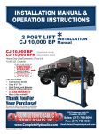
INSTALLATION MANUAL &
OPERATION INSTRUCTIONS
2 POST LIFT
CJ 10,000 OHA
*
INSTALLATION
Manual
CJ 10,000 OH (Symmetric Arms)
CJ 10,000 OHA (Asymmetric Arms)
Heavy-Duty DualSymmetric 2 Post
ost Lift
10,000 LB. Capacity
Call Your Distributor Today!
EXTENDED
WARRANTY
Protect Yourself For An
Additional 12 Months
Contact Distributor For Details!
Warranties Go Away
Equipment Stays!
LIFT FEATURES:
• Commercial Grade
• Only 11’ 11” Tall
• Dual Point Lock Release
• Drop-In Lifting Adapters
• 5 YEAR WARRANTY
• More Lifts Available!
Thank You For
Your Purchase!
We reserve the right to make changes in speci¿cations
without notice and without making changes retroactive.
130 Commerce Park Dr.
Franklin, IN 46131
www CompleteHydraulic com
www.CompleteHydraulic.com
Volume: 01.05.2009 12:16 PM
Sales: (317) 736-5094
Fax: (317) 738-0555
Email: [email protected]
INFORMATION ABOUT THIS LIFT:
Model No.:
Capacity:
2 Post Lift: CJ 10,000 OHA
INSTALLATION manual
CJ 10,000 OH(A)
10,000 lbs.
Serial No.:
Installation Date:
Distributor:
Dist. Phone Number:
Installer:
Installer Phone Number:
COMPLETE HYDRAULIC
SERVICE & SALES, INC.
Volume: 01.05.2009 12:16 PM
www.CompleteHydraulic.com
2 of 30
Introduction / Table of Contents
2 Post Lift: CJ 10,000 OHA
INSTALLATION manual
INSTALLATION & MAINTENANCE
MANUAL FOR C.H.S.S.I. TWO-POST
“CJ 10,000 OHA” VEHICLE LIFT!
(10,000 POUND MAXIMUM CAPACITY)
(Catalog Number: CJ 10,000 OHA)
TABLE OF CONTENTS
READ THIS BEFORE INSTALLING THE LIFT ......................................................4
TOOLS FOR INSTALLATION ................................................................................4
BOLT BOX CONTENTS.........................................................................................5
SPECIFICATIONS ............................................................................................. 6-7
INSTALLATION ................................................................................................ 8-12
POWER UNIT WIRING DIAGRAM ......................................................................13
HOSE ROUTING & POWER UNIT ......................................................................14
MANUAL RELEASE HANDLE POWER UNIT .....................................................15
ADJUSTMENTS ............................................................................................ 16-18
MAINTENANCE & SAFETY .......................................................................... 19-24
TROUBLESHOOTING .........................................................................................25
WARRANTY.........................................................................................................26
NOTES.................................................................................................................27
DISTRIBUTOR INVITATION ................................................................................28
WARRANTY ACTIVATION FORM .......................................................................29
READ THIS MANUAL
COMPLETELY
BEFORE
C
INSTALLING LIFT!!!
DISTRIBUTED BY:
COMPLETE HYDRAULIC SERVICE & SALES, INC.
130 COMMERCE PARK DRIVE
FRANKLIN, IN 46131
(317) 736-5094
Web: www.CompleteHydraulic.com
E-mail: [email protected]
COMPLETE HYDRAULIC
SERVICE & SALES, INC.
Volume: 01.05.2009 12:16 PM
www.CompleteHydraulic.com
3 of 30
2 Post Lift: CJ 10,000 OHA
INSTALLATION manual
READ THIS BEFORE INSTALLING THE LIFT!
Improper installation can cause injury or damage!
1. Read this installation and operation manual in its entirety before attempting to install
the lift. Manufacturer or Distributor assumes no responsibility for loss or damage of any
kind, expressed or implied, resulting from improper installation or use of this lift. Always use
professional installation companies.
2. All persons using this equipment must be responsible, quali¿ed, and carefully follow the operation
and safety guidelines contained in this manual.
3. A level Àoor is required for proper lift installation and operation.
4. DO NOT install this lift on any asphalt surface. Only on concrete surface a minimum of 4” thick
and 3,500 psi tensile strength with steel or ¿ber mesh reinforcement.
5. DO NOT install this lift over concrete expansion joints or cracks. (Check with your building
architect.)
6. DO NOT install this lift on an upper Àoor without written authorization from your building architect.
Should only be installed on basement Àoor.
7. DO NOT attempt to lift only part of a vehicle. This lift is intended to raise the entire body of a
vehicle only. This will bend the arms and void the warranty.
8. DO NOT attempt to use the overhead beam to lift engines, or any other parts out of a vehicle.
Doing so will bend the overhead beam and void the warranty.
9. NEVER lift any persons or vehicles containing persons. This lift is designed to lift empty vehicles
only.
TOOLS FOR INSTALLATION
Concrete Rotary Hammer Drill with 3/4 inch Carbide Bit
Rubber Hammer
Chalk line
Sockets and Open End Wrenches
Ratchet Driver
Vice Grips
Measuring Tape
Screwdrivers
Torque Wrench
Step Ladder
4 Foot Bubble Level
12 Inch Crescent Wrench
AW32 Non-Foaming Hydraulic Fluid (4 gallons)
COMPLETE HYDRAULIC
SERVICE & SALES, INC.
Volume: 01.05.2009 12:16 PM
www.CompleteHydraulic.com
4 of 30
2 Post Lift: CJ 10,000 OHA
INSTALLATION manual
BOLT BOX CONTENTS
QTY
1
1
2
6
10
9
1
4
2
4
1
1
4
4
2
1
1
1
1
2
1
1
2
1
1
2
PART DESCRIPTIONS
Power Unit Hydraulic Fitting Straight Thread O-Ring Branch Tee C5715 X 6
Overhead Safety Limit Switch (250V - 5A) Blue & Yellow & 4 Screws
Over Head Safety Cable Clevis Screw 4 Flat Washers, 3 Lock washers 1 Nut
(Sometimes Not Used)
Column Hydraulic Hose Clamps With 6, ¼ Screws
Anchor Bolt 3/4 x 5 1/2" With Flat Washers & Nuts
½ Bolts x 1 ½ Long For Overhead Cross Beam For Mounting To Column Extensions
Extension Hydraulic Fitting (Extra Sometimes Not Used)
5/16 x 1” Mounting Bolts For Hyd. Power Unit, W/ 2 Flat Washers, 1 Lock Washer &
1 nut
Rubber Grommets For Hydraulic Hose To Run Through For Extensions
Arm Pins 1 ½ x 7 1/16 Long
Hydraulic Hose Long
Hydraulic Hose Short
Black Truck Adapters Screw Up Style 2” Diam. x 6 ¼ Long End To End
Carriage Lift Arms
Lock Handle With Ball For Arm Restraints (Sometimes Already Mounted on
Carriage)
Hydraulic Power Unit 220 Volt / 30 AMP Breaker w/ Manual Release Handle
CHSSIMRH220V
Overhead Safety Bar Padding For Shut Off Bar Approx. 6’ 6”
Overhead Safety Bar Approx. 7/8 x 93
Overhead Safety Bar Wire To Wire Safety Switch To Power Unit Circuit Approx 11’ 8”
3/8 x 33’ 8 ½ Inch Wire Rope Equalizer Cables (Sometimes Already Attached To
Carriages) W/ 5/8 Threads On 6” Long W/ 8, 5/8 Nuts & 4, 5/8 Flat Washers
Short 65.5” x 3/8 Hydraulic Hose W/ Female JIC #6 Straight Fittings
Long 28’ 6” x 3/8 Hydraulic Hose W/ Female JIC #6 Straight Fittings
32” Top Column Extensions (Bolted Upside Down Inside Each Column W/ Pulleys
Attached)
(A) Top Overhead Cross Beam Approx. 61 ¾ Long
(B) Top Overhead Cross Beam Approx. 58” Long
Columns 9’ 3” Tall
COMPLETE HYDRAULIC
SERVICE & SALES, INC.
Volume: 01.05.2009 12:16 PM
www.CompleteHydraulic.com
5 of 30
CJ 10,000 OHA SpeciÀcations
2 Post Lift: CJ 10,000 OHA
INSTALLATION manual
2’-8”
Distance Between Posts:
110¼”
11’-11”
Drive Through Clearance:
107½”
134½”
COMPLETE HYDRAULIC
SERVICE & SALES, INC.
Volume: 01.05.2009 12:16 PM
www.CompleteHydraulic.com
12”
6’-0”
Lifting Height
6’-8”
102”
9’-3”
6 of 30
2 Post Lift: CJ 10,000 OHA
INSTALLATION manual
CJ 10,000 OHA SpeciÀcations
CJ 10,000 OH
Symmetric (50/50)
WALL
WALL
Arm
Dimensions:
Center of Pin to Center of
Lifting Pad Measurements:
IN:
OUT:
12 FT.
Minimum
14”
32”
45”
Back of Arm to Front of Arm:
IN:
OUT:
36¼”
49½”
18”
11’ 2”
12”
CJ 10,000 OHA
Asymmetric (30/70)
WALL
WALL
Short Arm
Dimensions:
Center of Pin to Center of
Lifting Pad Measurements:
12 FT.
Minimum
IN:
OUT:
29½”
40¼”
Back of Arm to Front of Arm:
IN:
OUT:
33”
44½”
18”
Long Arm
Dimensions:
Center of Pin to Center of
Lifting Pad Measurements:
IN:
OUT:
39”
57½”
Back of Arm to Front of Arm:
IN:
OUT:
11’ 2”
All measurements are approximate
COMPLETE HYDRAULIC
SERVICE & SALES, INC.
Volume: 01.05.2009 12:16 PM
•
44”
62”
12”
Drawings are not to scale
•
Overall lift height is 11’ 11” tall
www.CompleteHydraulic.com
7 of 30
2 Post Lift: CJ 10,000 OHA
INSTALLATION manual
Installation
INSTALLATION & OPERATION MANUAL
Your lift is designed for many years of trouble-free service
when properly installed & maintained. Please take the time to
read this Installation Manual before proceeding.
INSTALLATION TIPS
This Lift is built from very heavy metal material. Use proper lifting techniques when lifting individual
pieces. Use plenty of help when moving Lift pieces. It is a good idea to wear work gloves to protect
your hands.
This Lift is designed to be installed on a minimum of 4” thick, 3500 psi, wire or ¿berglass reinforced
concrete. Do not install this Lift on asphalt, wood, or any other surface other than described. A level
surface is recommended.
Do not install this Lift over expansion joints or cracks. Check with your quali¿ed engineer or architect.
Do not install Lift over a basement or on any level other than ground level (i.e. second Àoor) without
written authorization from your building engineer or architect.
Improper installation can cause damage or injury. Manufacturer will assume no liability for loss or
damage of any kind, expressed or implied, resulting from improper installation or use of this product.
Read this installation manual in its entirety before attempting to install this lift.
LIFT STRUCTURE INSTALLATION
Determine where the lift is to be installed. Make sure there is enough room in front,
behind, above and on the sides of the lift. See (FIGURE 1) for proper dimensions.
Layout with a chalk line your concrete Àoor to the proper layout you want and check for proper
clearances.
Remove any loose Cables, Hoses, Part Boxes, Hydraulic Power Unit, etc. if they are inside the columns
or banded to the columns.
Remove the Power Unit Box and four Swing Arms from the Lift. Next remove the bolts holding the two
columns together. Remove the Top Column from the Bottom Column out of the shipping crate and
discard the steel.
Unbolt the 4 bolts at the end of each Column and slide the Overhead Extensions out of the Columns. Turn the
Extensions 180 degree and rebolt the Extension to the top of each Column where you just unbolted them. Place
the opening of the Extension to the inside, just like the carriage opening. There are 2 rubber grommets for the
Hydraulic Hose to pass through in the parts box. Install them in the top of each extension where the cut out area
is.
Stand up the Power Unit Column (the one with the power unit bracket welded on it) and position it inside the
chalked lines to your chalked out dimensions. It is recommended that this column be placed on the passenger
side of the car, but it can go on the driver’s side if desired. Keep in mind this is the Column where your main
electrical power supply will be connected and your hydraulic Power Unit is attached. The Column should face
straight toward the other Column. (Continued Next Page)
COMPLETE HYDRAULIC
SERVICE & SALES, INC.
Volume: 01.05.2009 12:16 PM
www.CompleteHydraulic.com
8 of 30
Installation
2 Post Lift: CJ 10,000 OHA
INSTALLATION manual
Stand up the other Column just opposite the main Power Unit Column inside the chalk lines as shown as you see
it in (FIGURE 1) to your dimensions. Using a tape measure, measure from the back corner to the back corner of
the base to ensure the Columns are square to each other. Adjust as necessary to obtain best ¿t and still provide
good passage.
Now drill 5 holes in for 1 Column and place the Anchors as you go in the holes. Do not tighten Anchor Bolts at
this time. Hammer drill all the way through the cement Àoor.
Using a level check the 1 Column to insure it is level side-to-side and front to back.
Anchor the Column using the 5 ¾” X 5 ½” Anchors that are provided. If shimming is required in leveling the
Columns, keep the Shims as close to the Anchors as possible by using shim stock. If ½ inch or more of shim
is required, either re¿nish concrete or use steel plates and extra long Anchor Bolts (FOR EXTRA PLATES OR
LONGER ANCHORS CALL YOUR LIFT DISTRIBUTOR). Tighten 5 ¾” X 5 ½” Anchor Bolts and recheck for level
and plum. Hammer the Anchor Bolts all the way down. Tighten Anchor Bolts using a torque wrench to 125
ft. / lbs. (DO NOT use an impact gun when tightening the Anchor Bolts!) NOTE: 4” - 6” of embedment is
the minimum requirement for reinforced concrete.
Now bolt the 2 piece Overhead Cross Bar together on the Àoor and assemble the Overhead Safety Shut Off Bar
and Switch as necessary to the Overhead Bar see (FIGURE 2). Using a helper lift the overhead assembly to the
top of the Column Extensions and bolt the Overhead to the top of the Extensions on each side with the opening
of the Overhead Cross Bar facing upward to enable you to run the Cables and the Hydraulic Hose through the
Cross Bar at the top without allowing the Hose to rub against the Cables.
After completing the installation of the Overhead Beam, level the 2nd Column and Shim, as necessary. Drill the
other 5 Anchor Holes as you did the 1st Column and tighten Anchor Bolts using a torque wrench to 125 ft. /
lbs. (again, DO NOT use an impact gun when tightening the Anchor Bolts!).
Now, manually lift both Carriages on each Column about waist high. Let the Carriages down allowing them to set
on the Lift Safety Lock Stops. Make sure they are at the same height and on the Safety Lock Stops. Check to
insure the Cylinders are properly seated into the Cylinder Hole in the Base Plate. If they are properly seated the
round part of the Cylinder will be sitting down on the steel Àat and Àush.
If the Equalizer Cables are not attached to the Lift Carriages, do the following: Take the 3/8” X 33’ 8 1/2” Equalizer
Cables and place a ¾” SAE Àat washer over the threads and onto the Cable. Using vise grips and a socket,
tighten the Cable Nut half way down the threads. See (FIGURE 3) for proper cable routing. Tighten the Nuts on
the threads until the proper slack is out of the Cables much like a banjo string or a fan belt.
COMPLETE HYDRAULIC
SERVICE & SALES, INC.
Volume: 01.05.2009 12:16 PM
www.CompleteHydraulic.com
9 of 30
Extensions & Overhead Beam
2 Post Lift: CJ 10,000 OHA
INSTALLATION manual
Use 4 bolt sets on each side of
the Overhead Beam to mount
the Overhead Assembly to the
tops of the Column Extensions.
11’ 8” Cable from the Overhead
Cutoff Switch to the Power Unit,
See Figure 4 for Wiring Diagram.
Slide Foam Rubber Pad over
the Overhead Safety Cut Off
Bar before installing the Bar.
Mount the Overhead
Cutoff Switch to the
Bracket with 4 Screws.
Install Pin and Retaining
Clip to hold the Padded
Cut Off Bar in place.
Use 4 sets of Bolts to attach
the 2 Column Extensions to
the two 9’ 3” Column Bases
COMPLETE HYDRAULIC
SERVICE & SALES, INC.
Volume: 01.05.2009 12:16 PM
www.CompleteHydraulic.com
10 of 30
2 Post Lift: CJ 10,000 OHA
INSTALLATION manual
Installation
CABLE ROUTING DIAGRAM
Cables are routed over the Pulleys at the tops of the
Columns through the Overhead Beam Assembly.
PASSENGER’S SIDE
CARRIAGE
DRIVER’S SIDE
CARRIAGE
CABLE #2
PASSENGER’S SIDE
CARRIAGE
DRIVER’S SIDE
CARRIAGE
CABLE #1
These Pulleys Are Located
At The Base Of The Columns.
FIGURE 3
COMPLETE HYDRAULIC
SERVICE & SALES, INC.
Volume: 01.05.2009 12:16 PM
www.CompleteHydraulic.com
11 of 30
2 Post Lift: CJ 10,000 OHA
INSTALLATION manual
Installation
CONNECTING POWER UNIT & HYDRAULIC HOSES
Using the four 5/16” X 1” Bolts mount the Power Unit to the Main Side Column.
Install the TEE Fitting with o-ring end going into the Power Unit in the hole that is stamped “P”
(For Pressure).
Connect the 3/8” x 65 ½” SHORT Hydraulic Hose to the bottom of the Tee Fitting and run the Hose
down the side of the Column and connect it to the end of the 90-degree Elbow at the bottom of the
Column. Do not over tighten, as you will crack the Fitting. Secure the Hose to the Column by using
one of the 6 hose clamps and screws that are in your parts box.
Connect the 3/8” x 28’ 6” LONG Hydraulic Hose to the driver’s side Hydraulic Fitting at the bottom of
the Column Hydraulic Cylinder outside the Column. Run the Hose up the Column and through the
Rubber Grommet that is in your parts box (you should have already installed the Rubber Grommet into
the Overhead Cross Beam for the Hose to run through). Run the Hose across the Cross Beam going
through the round welded guides. Go across the entire Overhead through the Rubber Grommet on
the Power Unit side and down to the Tee Fitting at the Power Unit and tighten the Fitting. Secure the
Hydraulic Hose with the screws & hose clamps provided on both sides of the Columns.
See (FIGURE 5) for Hose layout and routing the Power Unit.
INSTALLING SWING ARMS
Locate the 4 Swing Arms and Swing Arm Pins. The Pins are in the misc. parts box. Take one of the
Arms and insert it over the hole in the Carriage Torsion Tube. Line up the holes and insert the Pin.
Repeat for the three other Arms. Asymmetrical lift; owners the Short Arm with the crook in it goes
closest to the front of the vehicle as your pulling into the Lift.
ELECTRICAL CONNECTION
IT IS BEST TO HAVE A QUALIFIED ELECTRICIAN HOOK THE MAIN ELECTRICAL POWER
CONNECTION TO THE POWER UNIT AND THE OVERHEAD SAFETY CUT OFF BAR SWITCH.
FOLLOW LOCAL CODES IN YOUR AREA.
The electricity is to be hooked up to the Power Unit. There are 2 wires inside the electrical box on the
Motor. Make a connection with the 2 loose wires inside the motor box with 2 wires from your main
power supply to the Lift. The power supply to the Lift should be 220 volt with a 20 amp breaker. Attach
the ground wire to the back of the box with the screw if it is not connected. This is a 220-volt Power
Unit. Green is usually the ground wire. Wire the Overhead Safety Bar Cut Off Switch in a series so
when the Switch is activated it will shut down the power to the Hydraulic Motor when you are raising a
vehicle.
See (FIGURE 4) for electrical connections.
NOTE: Power Unit Wiring (Choose One)
1. If You Have The Power Unit With The Clear Tank Use Wiring Diagram 1.
2. If You Have The Power Unit With The Black Tank Use Wiring Diagram 2.
COMPLETE HYDRAULIC
SERVICE & SALES, INC.
Volume: 01.05.2009 12:16 PM
www.CompleteHydraulic.com
12 of 30
2 Post Lift: CJ 10,000 OHA
INSTALLATION manual
Power Unit Wiring Diagram
Note: Power Unit Wiring (Choose One):
Overhead Safety
Switch mounted to
the Overhead Safety
Bar Bracket on the
Power Unit Side.
1. If you have an SPX or Monarch
Power Unit (Clear Tanks), use
wiring diagram 1.
2. If you have an Applied Power
Unit (Black Tank), use wiring
diagram 2.
Approx. 11’ 8” Cord
Supplied With The Lift
FIGURE 4
Power Unit
Motor
This is your 220 Volt AC
incoming power supply
off of a 20 Amp breaker.
Attach the Black Wire
to either of the 11’ 8”
Overhead Safety Switch
Wires.
Attach the White Wire
to the Push Button
Switch.
White
Black
Green / GRND
See the push button
switch detail below.
Connect either wire from the
Overhead Safety Switch Cord
to the Black Wire on the top of
the Push Button Switch.
Connect the White Wire
from the 220 Volt Breaker
Box to the White Wire 2nd
terminal down on the switch
See the detail
below on how
to wire the
Push Button
Switch
Black
Push
Button
Switch
White
Diagram 1
Fixed wiring to the motor from the factory.
Connect one motor wire to the
terminal marked “C” on the switch.
C
Connect one power wire from
your 220 Volt Breaker Box to
the center terminal marked
“N.O.” on the switch
N.O.
N.C.
FIGURE 4
Push
Button
Switch
Diagram 1
Connect the other power wire
from your 220 Volt Breaker
Box to the other wire from the
motor.
COMPLETE HYDRAULIC
SERVICE & SALES, INC.
Volume: 01.05.2009 12:16 PM
www.CompleteHydraulic.com
13 of 30
Hose Routing & Power Unit
2 Post Lift: CJ 10,000 OHA
INSTALLATION manual
Run The Hose Through The Crossbar Eyelets And
Overhead Beam To Ensure That The Equalization
Cables Do Not Rub The Hose.
Attach One End Of
The 28’ 6” Hose
To The Top Of “T”
Fitting In The “P”
Port Of The Power
Unit And The Other
End Of The Hose
To The Fitting At
The Bottom Of The
Hydraulic Cylinder.
Attach One End Of The 65.5”
Hose To The Bottom Of The
“T” Fitting In The “P” Port
On The Power Unit And The
Other End Of The Hose To
The Fitting At The Bottom Of
The Hydraulic Cylinder.
65.5” Hose
CYLINDER 1
CYLINDER 2
NOTE:
Should There Be A 90º Fitting
in The “P” Port Of The Power
Unit, Remove it and Replace
It With The “T” Fitting In The
Parts Bag.
FIGURE 5
COMPLETE HYDRAULIC
SERVICE & SALES, INC.
Volume: 01.05.2009 12:16 PM
www.CompleteHydraulic.com
14 of 30
Manual Release Handle Power Unit
SPX
2 Post Lift: CJ 10,000 OHA
INSTALLATION manual
DO YOU HAVE THIS STYLE
HYDRAULIC POWER UNIT?
IF SO, SEE NOTES BELOW!
Fill Here
Fill Line
Fill to this line, takes
approx. 3 gallons.
Monarch
Fill Here
Ground Wire
(INSTALLATION OF THE ELECTRICAL
TO THE POWER UNIT IS TO BE DONE
ONLY BY A CERTIFIED ELECTRICIAN.
BEFORE THE POWER UNIT IS
INSTALLED, HAVE THE ELECTRICIAN
WIRE
A
QUICK
DISCONNECT
BETWEEN THE MAIN POWER
BREAKER BOX AND THE CONTROL
BOX, THEN HAVE THIS QUICK
DISCONNECT MOUNTED TO THE
SIDE OF THE COLUMN NEXT TO THE
POWER UNIT.)
Remove the junction box cover on the Motor.
Run your electrical power wires from the Main
Breaker Box with a 220 Volt Single Phase on
a Dedicated 20 Amp Breaker.
Remove the knock out hole on the side/top
(depending on the type of Power unit) of the
Junction Box on the Motor. Line the hole with
a Strain Relief. Now run your main power
wires through the knock out hole on the
side/top of the Motor Junction Box to make
the electrical connection to the switch wires
inside the box.
SEE PAGE 13 FOR WIRING TO SWITCH.
Attach the Green Wire to the Ground Screw
on the Motor in the back of the Motor Junction
Box.
Put the Junction Box Cover back on after the
wiring is complete.
COMPLETE HYDRAULIC
SERVICE & SALES, INC.
Volume: 01.05.2009 12:16 PM
www.CompleteHydraulic.com
15 of 30
2 Post Lift: CJ 10,000 OHA
INSTALLATION manual
Adjustments
HYDRAULIC FLUID
In some cases remove the Red or Black hex head plug from the Tank at the top where you are going to
¿ll the Tank with Àuid. Remove the black vent cap from the bottom of the Tank as this is just screwed
into a blind hole. It will not leak out any oil that you may put in the Tank. Now, screw the Red or Black
plug into the bottom of the Tank where you just removed the black vent cap. Put the vented plug in the
top after ¿lling with oil. Place a funnel into ¿ll hole and ¿ll the Tank with one of the following Àuids as
below. When the oil is about 1 inch from the bottom of the hole that is your full mark. Re¿ll the Tank
after running the Lift up and down a few times to bleed out the air from the Cylinders and Hoses. There
is no bleeding procedure except for running the Lift up and down 3 times. Do not ¿ll the Tank with the
Lift up as you will over¿ll the Tank and it will discharge out when you lower the Lift. Only top off Tank
with Lift Carriages on the Àoor
When ¿lling the Hydraulic Tank use the following Àuids.
•
AW 32 Hydraulic Oil
•
Dexron III Automatic Transmission Fluid
This Tank will hold approximately 16 quarts or 4 gallons when ¿lled 1 inch below the vent plug.
ADJUSTING CABLES
Place a pair of small or medium vise grips around the shoulder of the long threaded adjusting bolt on
the Cable to make any adjustments.
Use a deep socket to adjust the slack out of the Cable. Adjust tension to Cables equally.
Do not over tighten. Note: If one of the Cables is tighter than the other, the carriage will go up
uneven. These should be tightened like a Banjo String or Fan Belt.
ADJUSTING & SYNCHRONIZING THE CARRIAGES
One of the most important things to remember is not to tighten down one side more than the other.
The key is to tighten one side a half dozen turns then the opposite side a half dozen turns. After getting
both Cables equally tight (YOU SHOULD BE ABLE TO MOVE THE CABLES ABOUT AN INCH BACK
AND FORTH WITH SLIGHT PRESSURE LIKE A FAN BELT OR A BANJO STRING) raise the Lift
all the way up by pressing the up button on the Power Unit. Do not bottom the Lift out at the top by
holding down on the Switch.
Raise the Lift off the locks by pushing the Power Button, this will enable you to pull each release cable
ring located at the bottom of both carriages. See (FIGURE 6). Pull down on the Lowering Valve
Handle on the Power Unit and lower the Lift all the way to the Àoor. Raise the Lift again and listen
for the clicking of the Safety Locks in each Column. Determine which side is slower and tighten the
adjusting bolt on the opposite side carriage. Remember to only tighten a few turns at a time until the
Locks click at the same time when raising the Lift. Cycle the Lift up and down and listen to the Safety
Latches clicking and make the proper adjustment. Adjust until the carriages are with-in a ¼” of each
other or the clicks are almost at the same time with each side. When Cables are adjusted properly they
should be fairly tight.
COMPLETE HYDRAULIC
SERVICE & SALES, INC.
Volume: 01.05.2009 12:16 PM
www.CompleteHydraulic.com
16 of 30
2 Post Lift: CJ 10,000 OHA
INSTALLATION manual
Adjustments
DUAL POINT LOCK RELEASE
To disengage the Locking
System, raise the Lift up off of
the Locks, and then pull the
rings located at the bottom of
each carriage.
FIGURE 6
COMPLETE HYDRAULIC
SERVICE & SALES, INC.
Volume: 01.05.2009 12:16 PM
www.CompleteHydraulic.com
17 of 30
2 Post Lift: CJ 10,000 OHA
INSTALLATION manual
Adjustments
FINAL ASSEMBLY
Check all Bolts and Nuts to make sure they are tight. Do not use an impact gun on Concrete Anchors.
Check all Fittings for leaks. If necessary make sure the Arm Lock Restraints are engaging properly
and smoothly. If not, tap the Main Lock forward or backward as needed with a rubber mallet to insure
proper engagement on all 4 gears with the Arm Restraint Locks.
Cycle Lift up and down to insure Carriages are synchronized.
Place a vehicle on the Lift and raise until Swivel Pads are in contact with the frame of the vehicle.
Raise the vehicle up about 3 feet and lower until the tires touch the Àoor. Keep raising and lowering the
vehicle increasing the height each time until the vehicle is completely to the top. This procedure pumps
all the air from the system. Now the lift is ready for use.
OPERATION
1. Center vehicle left and right between the Posts.
2. Position the Swivel Pads under frame of vehicle at the proper lifting points.
3. Push the Up Button and raise the Lift until the Swivel Pads make contact with lifting points.
4. Check all Swivel Pads to make certain all Adapters are making full and proper contact.
5. Raise vehicle approximately 2 feet and check the stability by rocking the vehicle from the bumper.
6. Raise vehicle to the desired height and lower on to the Locking Device. Never leave the vehicle
suspended off the Locks.
7. To lower, raise the Lift off the Locks by 2” then pull the Lock Release Cable Ring on each Carriage
downward releasing the Lock Release and lower slowly.
8. After lowering, rotate the Swing Arms back out of the way.
Manual Push
Button (UP)
Manual Release
Handle (DOWN)
1. UP Button - Used to raise the Lift
*NOTE: This button must also be
used to raise the Lift up off of the
Safety Locks before the Lift can be
lowered.
2. DOWN Handle / Lever - Use this
Manual Release Handle to lower
the Lift. This Lever is also used to
lower the Lift onto the Safety Locking
system. *NOTE: To lower the Lift,
you must ¿rst raise the Lift up off of
the Safety Locks & Disengaged the
Locks using the Single Point Lock
Release Handle before the Lift can
be lowered.
NOTE: The CJ 10,000 OHA comes with a “MRH” (Manual Release
Handle) Power Unit, this unit serves as both the Power Unit and
Control Box for your Lift.
COMPLETE HYDRAULIC
SERVICE & SALES, INC.
Volume: 01.05.2009 12:16 PM
www.CompleteHydraulic.com
18 of 30
Maintenance & Safety
2 Post Lift: CJ 10,000 OHA
INSTALLATION manual
MAINTENANCE
Lubrication:
Lubricate all Nylon Wear Block Corners inside each Post with heavy duty bearing grease once every
six months. Lubricate Chains every six months.
Anchor Bolts:
During ¿rst week of use, check Anchors daily. Do not use an impact wrench. After ¿rst week, check
once a month for the ¿rst six months. Tighten as necessary.
Concrete:
Check concrete for stress cracks daily for the ¿rst two weeks of use as a precaution. Thereafter, check
monthly. Check all Bolts and Nuts every six months.
Hydraulic Oil:
If your Lift will raise all the way to the top the Hydraulic Tank is full of hydraulic oil. The hydraulic oil
should be changed once a year, along with cleaning the Suction Filter.
SAFETY LATCH ADJUSTMENT
Do not make any adjustments on the Lift or the Cables.
If the Safety Latch in either Column does not operate, use the following procedure to adjust it.
Raise the Lift until you can see the Latch through the access hole inside of the Column by removing the
2 Screws and the Cover.
Do not set Lift on Safety Latch for this adjustment. Allow the hydraulic system to hold the Lift up during
this adjustment. Do not have a vehicle on the Lift during this time.
Pull the Latch forward with a screwdriver.
If the Latch, is not working during ascent, tighten the Adjustment Bolt one full turn and test the Latch
and follow this procedure until the Latch operates.
If the Latch, is not working during descent, loosen the Adjustment Bolt one full turn and test the Latch
and follow this procedure until the Latch operates.
Latch and or Cable adjustments are normal maintenance and are not warranty items.
COMPLETE HYDRAULIC
SERVICE & SALES, INC.
Volume: 01.05.2009 12:16 PM
www.CompleteHydraulic.com
19 of 30
Maintenance & Safety
2 Post Lift: CJ 10,000 OHA
INSTALLATION manual
AUTOMOTIVE LIFT SAFETY TIPS
POST THESE SAFETY TIPS WHERE THEY WILL BE A CONSTANT REMINDER TO YOUR LIFT
OPERATOR. FOR INFORMATION SPECIFIC TO THE LIFT, ALWAYS REFER TO THE LIFT
MANUFACTURER’S MANUAL, YOUR DEALER, OR INSTALLER.
•
Inspect your Lift daily. Never operate the Lift if it malfunctions or if it has broken or damaged parts.
Repairs should be made with original equipment parts.
•
Operating controls & safeties are designed to close when released. Do not block them open or
override them at any time.
•
Never overload your Lift. Manufacturer’s rated capacity is shown on the serial # tag af¿xed to the
Lift above the Power Unit.
•
Only trained and authorized personnel should do positioning of vehicle(s) and operation of the Lifts.
•
Never raise vehicle with anyone inside it. Customer or bystanders should not be in the lift area
during operation.
•
Always keep lift area free of obstructions, grease, oil, trash and other debris.
•
Before driving vehicle over Lift, position Arms and Supports to provide unobstructed clearance. Do
not hit or run over Lift Arms, Adapter, or Axle Supports. This could damage Lift or vehicle.
•
Load the vehicle on Lift carefully. Position the Lift Supports to contact at the vehicle manufacturers
recommended lifting points. Raise the Lift until Supports contact the vehicle.
•
Check Supports for secure contact with the vehicle. Raise the Lift to desired working height.
•
CAUTION: If you are working under the vehicle, the Lift should be raised high enough for
the Locking Devise to be engaged. Always set the Lift down on the Safety Locks while your
using the Lift.
•
Note that with some vehicles, the removal (or installation) of components may cause a critical shift
in the center of gravity and result in raised vehicle stability. Refer to the vehicle manufacturer’s
service manual for recommended procedures when vehicle components are removed.
•
Before lowering Lift, be sure tool trays, stands, jacks, etc. are removed from under vehicle. Raise
the vehicle off the Locking Devices before attempting to lower the Lift and pull the Safety Lock
Rings under each Carriage.
•
Before removing vehicle from lift area, position Lift Arms and Supports to provide a safe
unobstructed exit.
COMPLETE HYDRAULIC
SERVICE & SALES, INC.
Volume: 01.05.2009 12:16 PM
www.CompleteHydraulic.com
20 of 30
Maintenance & Safety
2 Post Lift: CJ 10,000 OHA
INSTALLATION manual
NOTE: IT IS THE CUSTOMER’S OR THE END USER’S RESPONSIBILITY TO MAINTAIN THE
PROPER TENSION ON THE EQUALIZER CABLES. ASKING A QUALIFIED LIFT
TECHNICIAN TO RETURN IN THE FUTURE TO MAINTAIN THE CABLE ADJUSTMENTS
AFTER THE LIFT IS INSTALLED WOULD NOT BE A WARRANTY FOR THE
ADJUSTMENTS.
IF AT ANY TIME YOU’RE NOT SURE OF THE SAFE OPERATION OF THE LIFT,
DISCONTINUE USING IT AND CALL YOUR DISTRIBUTOR FOR ASSISTANCE.
TESTING AND ADJUSTING LIFT
With the power properly hooked up and hydraulic oil in the Pump Reservoir push the Push Button on
the side of the Motor to raise the Carriages off the Locks. Release the Push Button and then pull the
Lock Release Cable under each Carriage to release the Locks. Run the Lift all the way up and down
two more times to bleed all the air from the system.
While running the Lift, listen to the Safeties clicking. Each side should click simultaneously or with-in
a ½ second of each other. If they are not clicking together, then adjust the Cables to compensate by
tightening the side opposite the one that is clicking last at the Cable Bolt at the top of the Carriage on
the same side.
Remember not to over tighten Cables---they should be ¿rm, much like a banjo string or a fan belt in a
car.
COMPLETE HYDRAULIC
SERVICE & SALES, INC.
Volume: 01.05.2009 12:16 PM
www.CompleteHydraulic.com
21 of 30
Maintenance & Safety
2 Post Lift: CJ 10,000 OHA
INSTALLATION manual
GENERAL SAFETY INSTRUCTIONS
•
•
•
•
•
•
•
•
•
•
•
•
•
•
•
•
•
•
•
•
ALWAYS make sure the Lift is on the Locks before going under the vehicle and that they
work correctly.
NEVER allow anyone to go under the Lift when raising or lowering.
Care must be taken as burns can occur from touching hot parts.
Do not operate equipment with a damaged cord or if the equipment has been dropped or damaged
until a CHSSI Authorized Service Person has examined it.
To reduce the risk of ¿re, do not operate equipment in the vicinity of open containers of Àammable
liquids.
Adequate ventilation should be provided when working on internal combustion engines.
Keep hair, loose clothing, ¿ngers, and all parts of the body away from moving parts.
To reduce the risk of electrical shock, do not use on wet surfaces or expose to rain.
Use only as described in this manual.
Use only manufacturer’s recommended parts.
ALWAYS WEAR SAFETY GLASSES.
NEVER allow unauthorized personnel to operate Lift.
ALWAYS know the gross weight of vehicle.
NEVER EXCEED CAPACITY OF LIFT. (10,000 LBS)
NEVER use the Lift to raise one end or one side of vehicle.
ALWAYS keep unquali¿ed people away from area while loading, unloading, raising, or lowering the
Lift.
NEVER allow anyone to ride in the vehicle while raising, or lowering the Lift.
ALWAYS keep the area clean and free of water grease, and oil.
ALWAYS remove wheel chocks, tools, hoses, etc. before loading, unloading, raising, or lowering the
Lift.
ALWAYS ensure all cables are on all Pulleys at all times.
LIFT OPERATING INSTRUCTIONS
Swing the Front Arms to the front and the Rear Arms to the rear. Once Arms are in position, pull a car
into the bay. A general rule of thumb is to stop the car with the center of the wheelbase even with the
center of the Columns. Swing the Four Arms under the vehicle and position the Pads under the appropriate lifting points. (If you are not sure of the proper lifting points, you should check the vehicle's
service manual or contact the vehicle manufacturer).
Adjust the Screw Pads so they all hit their lifting points at the same time. This will allow the car to be
level when rising. With the Pads in their proper locations and no obstructions around the Lift or vehicle,
you may now press the Green Button on the Power Unit to raise the vehicle.
Raise the vehicle so that the tires are 6 inches off the ground. Walk to the back of the vehicle and push
up and down on the bumper. The vehicle will rock, but should not at any time lose contact with the
Swivel Pads. If the vehicle is bouncing off the Pads or feels at all unstable, you should lower it back to
the ground and reposition the Arms & Pads to balance the load. Repeat this process until the vehicle
is completely stable. When the vehicle is stable, you many raise the Lift all the way to the top. Listen to
Safeties clicking and adjust if necessary.
COMPLETE HYDRAULIC
SERVICE & SALES, INC.
Volume: 01.05.2009 12:16 PM
www.CompleteHydraulic.com
22 of 30
Maintenance & Safety
2 Post Lift: CJ 10,000 OHA
INSTALLATION manual
THE PROPER OPERATION OF THE LIFT REQUIRES THAT ANY TIME YOU RAISE A VEHICLE TO WORK
ON IT, YOU MUST LOWER THE LIFT ONTO THE SAFETY LOCKS. This is done by raising the vehicle to the
desired height and lowering the lift by pressing the red lowering button until the arms stop on the next available
lock.
To lower the vehicle, you must ¿rst raise the lift off of the locks using the green button. Then engage and hold
the lowering handle until the lift is on the ground.
NEVER WORK UNDER OR NEAR THIS LIFT WITHOUT THE LOCKS BEING ENGAGED. THE POWER
UNIT IS NOT DESIGNED TO BE A LOAD-HOLDING DEVICE. NOT USING THE LOCKS WILL RESULT IN
A PREMATURE FAILURE OF THE CYLINDERS, PUMP AND/OR CABLES AND CAN CAUSE SERIOUS
PROPERTY DAMAGE OR PERSONAL INJURY! FAILURE TO COMPLY TO THIS WARNING WILL RESULT IN IMMEDIATE TERMINATION OF YOUR WARRANTY.
MAINTENANCE SCHEDULE
The following periodic maintenance is the suggested minimum requirements and minimum intervals; accumulated hours or monthly period, which ever comes sooner. If you hear a noise or see any indication of possible
failure - cease operation immediately and inspect, correct and/or replace parts as required. Following these
maintenance procedures is the key to prolonging the useful life of your lift.
IF AT ANY TIME YOU’RE NOT SURE OF THE SAFE OPERATION OF THE LIFT, DISCONTINUE USING IT
AND CALL YOUR DISTRIBUTOR FOR ASSISTANCE.
WARNING: OSHA AND ANSI REQUIRE USERS TO INSPECT LIFTING EQUIPMENT AT THE START OF EVERY SHIFT. THESE AND OTHER PERIODIC INSPECTIONS ARE THE RESPONSIBILITY OF THE USER.
DAILY PRE-OPERATION CHECK
The user should at least perform the following checks daily and not use the Lift if anything is not correct.
•
•
•
•
•
•
•
•
•
Daily check of all Safety Locks & Arm Restraints - the discovery of device failure could save you
from expensive property damage, lost production time, serious personal injury and even death.
Check Safety Locks for free movement and full engagement with Lift, make sure the Arm Restraint
Gears mesh together completely and are working 100% each and every time the Lift is used. If not,
do not use the Lift.
Check Hydraulic Connections, and Hoses for leakage.
Insure Snap Rings at all Rollers, Sheaves and on all Screw-up Pads & optional Truck Adapters are
correct and safe.
Check All Bolts, Nuts, and Screws and tighten.
Check Wiring & Switches for damage and that they all work correctly.
Check for any stress cracks in the concrete Àoor near the Anchor Bolts which, if present, could
cause the Anchor Bolts to loosen and pull out of the Àoor. Do not use the Lift if this is apparent.
Check daily Anchor Bolts torque to 125 ft-lbs. Do NOT tighten using impact gun. NEVER use the Lift
with loose Anchor Bolts! All Anchor Bolts should be the correct torque speci¿cations.
Ensure all Cables are on all Pulleys at all times.
(Continued. Pg 24)
COMPLETE HYDRAULIC
SERVICE & SALES, INC.
Volume: 01.05.2009 12:16 PM
www.CompleteHydraulic.com
23 of 30
Maintenance & Safety
•
•
2 Post Lift: CJ 10,000 OHA
INSTALLATION manual
Check Equalization Cables: The Cables keep both sides of the Lift equal allowing the Safety Locks
to catch together. If one side of your Lift is running ahead of the other, it is most likely time to adjust
your Cables.
All of the Pulleys / Sheaves on your Lift should be sprayed with a light oil such as WD-40 or similar
lubricant, two to three times a year.
WEEKLY MAINTENANCE
•
•
•
•
•
•
Check anchor bolt torque daily to 125ft. lbs.
Check Àoor for stress cracks near anchor bolts
Check hydraulic oil level.
Check and tighten all bolts, nuts, and all screws.
Check all Cables are on all the proper Pulleys at all times.
Grease the inside of the Columns, where the Carriages run up and down.
YEARLY MAINTENANCE
•
•
•
•
All of the Pulleys / Sheaves on your Lift should be sprayed with a light oil, such as WD-40 or
similar lubricant, two to three times a year.
Check all Cables are on all the proper Pulleys each time you use your Lift.
Change the hydraulic Àuid - good maintenance procedure makes it mandatory to keep
hydraulic Àuid clean. No hard fast rules can be established; - operating temperature, type of
service, contamination levels, ¿ltration, and chemical composition of Àuid should be
considered. If operating in dusty environment a shorter interval may be required.
Grease the inside of the Columns, where the Carriages run up and down.
All repairs should only be performed by a CHSSI Authorized
Lift Installer.
•
•
•
•
•
•
Replacement of Hydraulic Hoses.
Replacement of Cables and Sheaves.
Replacement or rebuilding Hydraulic Cylinders.
Replacement or rebuilding Power Unit Pumps / Motors.
Checking Hydraulic Cylinder Rods and Rod Ends (threads) for deformation or damage.
Checking Cylinder Mounting for looseness and /or damage.
Relocating or changing components may cause problems. Each component in the system must
be compatible; an undersized or restricted line will cause a drop in pressure. All Valve, Pump, and
Hose connections should be sealed and/or capped until just before use. Air Hoses can be used to
clean Fittings and other components. However, the air supply must be ¿ltered and dry to prevent
contamination. Most important - cleanliness - contamination is the most frequent cause of malfunction
or failure of Hydraulic Equipment.
COMPLETE HYDRAULIC
SERVICE & SALES, INC.
Volume: 01.05.2009 12:16 PM
www.CompleteHydraulic.com
24 of 30
2 Post Lift: CJ 10,000 OHA
INSTALLATION manual
Troubleshooting
TROUBLE
CAUSE
SOLUTION
Pump/ Motor does not start
Improper electrical hook up
Blown fuse
Pump binding or stuck
Motor thermal overload tripped
Thermal overload in starter box
Tripped
Rewire
Replace fuse
Remove (Àush) or replace
Let Cool 30 sec.
Push button reset
Replace switch
Call Electrician
Pump/Motor operates but has
no pressure.
Wrong rotation of motor
Rewire
Pump/Motor operate low Àow
and/or low pressure (in raise
mode.) (in pressure mode)
Clogged inlet strainer
(cracking noise)
Relief valve leaking dirt on seat
Release valve leaking
Dirt on seat
Release stem out of adjustment
O-ring missing or cut
Relief valve setting too low
Clean strainer in solvent
Flush seat or ball seat again
Flush seat
Re-adjust stem setting
Replace o-ring
Replace
Pump/Motor operates but does
not hold system
Fitting loose
Check valve leaking
Dirt on seat
Release stem out of adjustment
O-ring missing or cut
Tighten or replace ¿tting
Flush seat
Re-adjust stem setting
Replace o-ring
Replace Motor
Failure to lower
Sticking release valves stem, or
out of adjustment
Replace stem and/or cartridge
Re-adjust stem setting
Air in oil
Loose inlet connection or low
oil level
Leaky or blown oil seals in pump
Siphon check does not seat
Tighten connection
Add oil
Replace oil seat
Replace
Motor does not run when
energized
Breaker thrown or fuse blown
Motor thermal overload tripped
Thermal overload in starter box
Tripped
Check micro switch
Faulty wiring, connections
Reset or replace
Wait for overload to cool
Push button to reset
Replace if necessary
Call Electrician
Oil blows out the breather /
¿lter port
Oil overload
Vehicle has been lowered too
fast
Remove to ½ - 2/3 full
Restrict lowering with
Manually controlled release
Cylinder will not lift load
Seal damage to piston
Oil leaking from cylinder front
Call factory / distributor for
instructions
Oil requirements
Use AW 32 Hydraulic Oil Dexron
III Automatic Transmission Fluid
Call factory / distributor for
instructions
COMPLETE HYDRAULIC
SERVICE & SALES, INC.
Volume: 01.05.2009 12:16 PM
www.CompleteHydraulic.com
25 of 30
Warranty
2 Post Lift: CJ 10,000 OHA
INSTALLATION manual
LIMITED LIFT WARRANTY
THIS LIMITED WARRANTY IS NOT TRANSFERABLE
FROM THE ORIGINAL RETAIL PURCHASER.
No warranty exists until each piece of equipment is completely
paid in full and the Lift Warranty Sheet has been returned to the
manufacture or master distributor.
Power Units are covered for defects in workmanship for one (1) year. Any misuse of Power Unit
will void this Warranty. For Power Unit Warranty repairs the original purchaser needs to provide
the following information: (1) Date code of the Power Unit, (2) Serial Number of the Power Unit,
and (3) Model Number. In cases of Power Unit replacements, you will be sent a replacement
Power Unit after billing your charge card. It is the Original Purchaser’s responsibility to properly
drain and box the defective Unit, tag it, and call UPS to pick it up and have it shipped back to us.
After receiving the Power Unit back to our facility, an inspection will be made to the Unit to insure
it was defective from the Manufacturer. If it is the manufacture’s defective Unit, we will credit
your credit card back, less any shipping. Failure to follow these procedures will void the Power
Unit warranty and any credit to your credit card.
Any wearable Lift part is not covered under warranty, such as Cables, Slide Blocks, Arms, Pullies,
Pins, Adapters, Pads, Switches, Hoses, & Fittings unless authorized by the manufacturer, and
which was not found to have been abused, will be repaired or replaced (at the Manufacturer’s
option). Defects caused by ordinary wear and tear, abuse, misuse, overloading, accident
(including shipping damages), improper maintenance and alterations are not approved by the
Manufacturer or Master Lift Distributor are speci¿cally excluded.
The Manufacturer reserves the absolute right to decline responsibility for repair work made or
attempted by any Company or Person not associated with, or approved beforehand, by the
Manufacturer. This Lift must be installed by a CHSSI Authorized Installer. Not having this Lift
installed by an Authorized Installer voids the Warranty.
WARRANTY LABOR IS NOT INCLUDED UNDER
WARRANTY. UNLESS EXPRESSLY APPROVED BY
THE MANUFACTURER, IN WRITING, BEFORE THE
REPAIRS ARE ATTEMPTED.
COMPLETE HYDRAULIC
SERVICE & SALES, INC.
Volume: 01.05.2009 12:16 PM
www.CompleteHydraulic.com
26 of 30
Notes
COMPLETE HYDRAULIC
SERVICE & SALES, INC.
Volume: 01.05.2009 12:16 PM
2 Post Lift: CJ 10,000 OHA
INSTALLATION manual
www.CompleteHydraulic.com
27 of 30
2 Post Lift: CJ 10,000 OHA
INSTALLATION manual
Distributor Invitation Letter
COMPLETE HYDRAULIC
SERVICE & SALES, INC.
MAKE IT HAPPEN
130 Commerce Park Drive
Franklin, IN 46131
(317) 736-5094 Of¿ce
(317) 738-0555 Fax
www.CompleteHydraulic.com
E-mail: [email protected]
SUCCESS IN QUALITY!
I would like to introduce you to COMPLETE HYDRAULIC SERVICE & SALES, INC. We are a Hydraulic Lift
Company specializing in Automotive Equipment as well as many other aspects of the Hydraulic Industry as you
will see in our “Sales Flyer” enclosed. This introduction comes to you as an invitation to be part of our Special
Distributor Program in your area that will include a “Protected Territory”.
We can offer you Special Lift Prices as a Distributor at an UNBELIEVABLE $1,649.95
with a Power Unit.
With this Special Pricing you will maintain a “Protected Territory” and
“FREE FREIGHT” with any container orders to your door with a 20 piece container order. Please see the CJ
10,000 OH Lift Brochure we have enclosed detailing speci¿cations of this particular lift or visit our web site www.
CompleteHydraulic.com. This Lift comes with a 5 Year Structural Warranty and a 1 Year Warranty on the Hydraulics
and Electrical. “WOW!” We sell over 500 Lifts per month of this style lift and are looking for Distributors to increase
this count to reach beyond all boundaries. Payments and Open Credit Options are based on Credit Approval. In
addition, we have other 2-Post Overhead & Base Plate Lifts, 4-Post Portable Lifts, Motorcycle Lifts, 14,000 lb. Four
Post & Alignment Rack Lifts, and a full line of Shop Equipment at UNBELIEVABLY low prices!
At this Low Low $1,649.95 Price, you have the opportunity to increase the Pro¿ts of your Business. I invite you to
visit our Warehouse at any time or you may contact me personally for an appointment, 317-736-5094, 24 hours a day, 7
days a week to discuss this program. You may also ¿nd our web site helpful to familiarize yourself with our company at
www.CompleteHydraulic.com or E-mail me at [email protected].
Thank You,
WOW!
Commercial Grade Lift
$1,649 .
95
Randy Brown / Chairman-C.E.O.
Complete Hydraulic Service & Sales, Inc.
130 Commerce Park Drive
Franklin, IN 46131
North American Division
(317) 736-5094 Of¿ce
(317) 738-0555 Fax
Free Freight With
h
A 20 Piece
Container Order!
COMPLETE HYDRAULIC
SERVICE & SALES, INC.
Volume: 01.05.2009 12:16 PM
CJ 10,000 OHA
www.CompleteHydraulic.com
28 of 30
WARRANTY ACTIVATION FORM
2 Post Lift: CJ 10,000 OHA
INSTALLATION manual
ATTENTION: MAIL TODAY TO ACTIVATE YOUR WARRANTY !
WARRANTY IS NON-TRANSFERABLE
Company Name: _______________________________________________________
Owner / Shop Manager: _________________________________________________
Address: _____________________________________________________________
Phone: (
) _____________Fax: (
) _____________Cell: (
) _____________
City/State/Province/Zip: _________________________________________________
E-mail: ______________________________________________________________
CJ 10,000 OHA
Model No.: CJ 10,000 OHA
Capacity: 10,000 lbs.
Serial No.:
Date:
Purchased From: ____________________________________ Purchase Date: ______
Address: ______________________________________________________________
City: ________________________________State: ___________________ Zip: _____
Of¿ce Phone: (
) ____________________ Cell Phone: (
COMPLETE HYDRAULIC
SERVICE & SALES, INC.
Volume: 01.05.2009 12:16 PM
) _________________
www.CompleteHydraulic.com
29 of 30
Complete Hydraulic Service & Sales, Inc.
130 Commerce Park Drive
Franklin, IN. 46131
www.CompleteHydraulic.com
E-mail: [email protected]
Place
Stamp
Here
Complete Hydraulic Service & Sales, Inc.
130 Commerce Park Drive
Franklin, Indiana 46131
ATTN.: Warranty Dept.
- - - - - - - - - - - - - - - - - - - - - - - - - - - - - - - - - - - - - - -- - - - - -- - - -- - - - -- - - - - - - - -