1
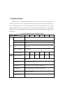
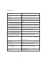
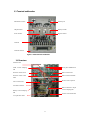
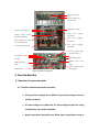
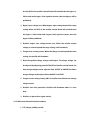
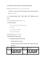
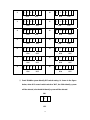
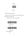
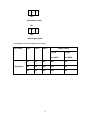
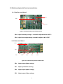
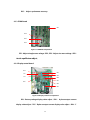
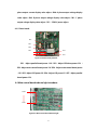
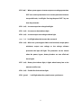
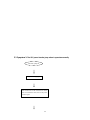
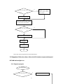
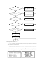
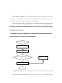
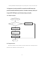
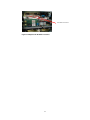
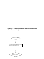
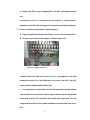
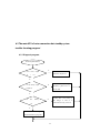
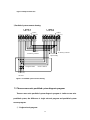
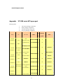
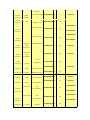
ST5100 series Maintenance Manual 10~60KVA www.allis.com.tw 1 Index 1. System overview ..........................................................................................................................4 2. Working principle .......................................................................................................................5 2.1 Working Principle Drawing .............................................................................................5 2.2 Working mode ...................................................................................................................6 2.3 The electrical connect drawing ........................................................................................7 3.The structure of UPS ...................................................................................................................8 3.1 Shape ..................................................................................................................................8 3.2 Display panel .....................................................................................................................9 3.3 Terminal and breaker ..................................................................................................... 11 3.4 Structure .......................................................................................................................... 11 4. Function describe ......................................................................................................................12 4.1 Function of system main parts .......................................................................................12 4.1.1 Rectifier control board function introduce: .......................................................12 4.1.2 Main control board function introduce:.............................................................13 4.1.3 PWM board function introduce:.........................................................................14 4.1.4 Display board function: .......................................................................................14 4.1.5 Rectifier driver board: Rectifier driver signal isolate and enlarge..................15 4.1.6 Inverter driver board: Inverter driver signal isolate and enlarge. ..................15 4.1.7 Bypass, inverter static switch driver board: Bypass, inverter output SCR driver isolate and enlarge. ............................................................................................15 4.1.8 Power board: Supply +12VDC、-12VDC、30VDC、5VDC、24VDC power to the system.......................................................................................................................15 4.1.9 Power backup and transfer board: Power transfer...........................................15 4.1.10 Fans control board:............................................................................................15 4.1.11 Parallel board: Parallel control function..........................................................15 4.2 Each board DIP switch setting:......................................................................................15 4.2.1 Display control board DIP switch setting:..........................................................15 4.2.2 Main control board DIP switch setting: .............................................................17 4.2.3 Rectifier control board DIP switch setting:........................................................18 4.3 Each board potential function introduction: ................................................................19 4.3.1 Rectifier control board: .......................................................................................19 4.3.2 Main control board: .............................................................................................19 4.3.3 SPWM board ........................................................................................................20 4.3.4 Display control board: .........................................................................................20 4.3.5 Power board: ........................................................................................................21 4.4 Main control board indicate light introduce: ...............................................................21 5. Some familiar symptoms and diagnosis ..................................................................................23 5.1 symptom 1:After close the power breaker or bypass breaker, the panel PHASE light 2 is on and the buzzer beep continually..................................................................................23 5.2 Symptom 2: The panel rectifier light is off, LCD display that rectifier is abnormal and the buzzer beep Intermittently. ....................................................................................24 5.2.1 Diagnosis program: ..............................................................................................24 5.2.2 Program describe: ................................................................................................24 5.3 Symptom 3: The UPS power breaker jump when it operation normally...................40 5.4 Symptom 4: When the utility is fail the UPS shut-down output and the panel BAT.LOW indicate light is on. .............................................................................................41 5.4.1 Diagnosis program: ..............................................................................................41 5.4.2 Program describe: ................................................................................................42 5.5 Symptom 5: In utility mode UPS is normal, but the battery breaker will jump off when it is turned on in battery mode...................................................................................43 5.6 Symptom 6: In utility mode UPS is normal, but the UPS battery low protection enable when battery breaker is turned on in battery mode, and the panel BAT.LOW light on and the buzzer beep continually.............................................................................44 5.6.1 Diagnosis program: ...........................................................................................44 5.6.2 Program describe: ................................................................................................44 5.7 Symptom 7: The UPS switch to bypass, panel FAULT indicate light on and buzzer beeps continually ...................................................................................................................46 5.8 Symptom 8: Close the bypass, power breaker, turn on the UPS and protection enable as soon as the inverter start......................................................................................52 5.9 Symptom 9:The protection enable as soon as the UPS switch to inverter output after it is turned on about 30 seconds. ..........................................................................................53 6. Series Connection Hot Standby System diagnosis program..................................................53 6.1 The standby UPS of series connection hot standby system diagnosis program:.....53 6.2 The main UPS of series connection hot standby system trouble-shooting program: .................................................................................................................................................55 6.2.1 Diagnosis program: ......................................................................................................55 6.2.2 Program describe: ................................................................................................56 7. Paralleled system trouble-shooting program:.........................................................................56 7.1 Two units paralleled system trouble-shooting program: .............................................56 7.1.1 Diagnosis program: ..............................................................................................56 7.1.2 Program describe: ................................................................................................57 7.2 Three or more units paralleled system diagnosis program: ........................................60 Appendix :ST5100 series UPS spare part................................................................................62 3 1. System overview ST5100 series UPS adopt advanced DSP control technique, it has a easy viewing and easy operating interface and a strong communication function, the structure design of the product is easy to maintenance, and it so has excellent EMC design, these make the product to be a high reliability UPS. The series have eight models: Single model ST5100-10KVA~ ST5100-60KVA and parallel model ST5100-10KVA~ST5100-60KVA, the technical specification is shown in the table below: SPECIFICATION input TAB 2-1 ST5100 SERIES TECHNICAL SPECIFICATION MODEL 10KVA 20KVA 30KVA 40KVA Voltage range (Vac) 380±25% Frequency range (Hz) 40~65 Synchronous range (Hz) 50±5% Phase 3φ4W+GND Battery voltage(VDC) 12V×29=348V Charge current(A) OUTPUT Rated power(KVA) 10 10 50KVA 10 15 15 20 20 30 40 50 Phase 3φ4W+GND Voltage(Vac) L−N:220 Frequency(Hz) Trace the mains when it is normal, else 50/60±0.2% Voltage stability 2%,permit three phase output load 100% unbalance Wave form Linear load THD<3% Switch time(ms) L-L:380 0 4 60KVA 20 60 Efficiency 90% Overload 125% of rated load last for 15min;150% of rated load last for 1min; Maintenance bypass Available DC start Available Input voltage, Frequency, Output voltage, Battery voltage, Load, DC LCD display OTHER current etc. LED display Operation status Alarm function Overload, AC input abnormal, Low battery, Failure, Over-temperature Communication function RS232/RS485, dry connection communication signal Battery test function Available Protect function Low battery, Overload, Overheat, Output short circuit, Output over voltage EMC Meets GB/T 7260.3-2003 standard Noise(dB) <65 Cooling mode Fans Working temperature 0∼40 (℃) Relative humidity 0∼95%, no condensation Dimension(W × D × H) 500×800×1180 (mm) 250 Weight (Kg) 300 320 350 450 460 2. Working principle 2.1 Working Principle Drawing Maintenance bypass Bypass Load AC source Filter Rectifier Inverter Utility Transformer Battery 5 2.2 Working mode When the utility is normal, the rectifier convert the AC input to DC power, it supply the inverter and charge the battery at the same time. Through the process of AC power changed to DC power, the inverter can supply more reliable and pure power to load, as the rectifier can dispel the problems of the portent, noise, unstable frequency and so on. When the utility is abnormal the battery connected to DC BUS will supply power to inverter, to protect load from AC power interrupting. when the inverter is failure (such as over-temperature, short circuit, output voltage abnormity, overload and so on), the inverter should shut off automatically. If the utility is normal at this moment, the switch will switch to bypass power to supply power to load. When you are maintaining, and the power must not be interrupted, you can shut off the inverter, and turn on the maintenance switch, then turn off the rectifier and bypass breaker. At this mode, AC power goes through maintenance switch to supply power to load. And at this time, there will be no any electricity in the UPS inside, and the maintenance person can work without any danger. 6 2.3 The electrical connect drawing 7 3.The structure of UPS 3.1 Shape 3-1 ST5100 series 10 60KVA shape 8 3.2 Display panel UPS 60KVA MODEL 60KVA INPUT 398V/50Hz OUTPUT 398V/50Hz >>>>>>>>>>>>======= Figure 3−3 Display panel 9 Figure descripe: (1)、LCD (2)、ON (3)、OFF (4)、Phase indicate light(red) (5)、Rectifier indicate light(green) (6)、Inverter indicate light(green) (7)、Bypass indicate light(red) (8)、Battery low indicate light(red) (9)、Overload indicate light(red) (10)、Fault indicate light(red) (11)、Page up Display UPS working parameters and status Press “ON” key for 1s will start inverter Press “OFF” key for 1s will shutdown inverter It will light when AC input is phase lose or phase wrong It will light when the rectifier works normally It will light when the inverter works normally It will light when the bypass output It will light when the battery low It will light when the UPS is overload It will light when the UPS is fault This key is display upward / parameter setting + function repeat. (12)、Enter (13)、Back (14)、Page down Push this key to confirm the function. Push this key to back to previous page. Push this key mean display downward / parameter setting -”. (15)、left Push this key to check the item LCD display or turn on background light 10 3.3 Terminal and breaker Maintenance switch Parallel port Output breaker Battery breaker Power breaker Bypass breaker Terminal Terminal describe Figure 3-4 UPS terminal and breaker 3.4 Structure Parallel board IGBT current sampling Three phase PWM board hall Rectifier control board Main control board Rectifier control board Main control board DSP DSP Rectifier filter capacitor Fans control board DC buffer contactor Main transformer output current sampling hall Battery current sampling hall Inverter main transformer AC input filter choke 11 Power supply board Power backup and transfer board Maintenance switch Inverter output capacitor Utility power sampling Parallel average current transformer sampling transformer Bypass power sampling Main transformer output transformer current sampling hall Fans Inverter main transformer power sampling transformer Inverter, bypass output SCR driver board Inverter driver board Display control board LCD display board DC fuse IGBT filter board Rectifier SCR driver IGBT board Rectifier output current Rectifier SCR sampling hall Figure 3-5 Structure of the UPS 4. Function describe 4.1 Function of system main parts 4.1.1 Rectifier control board function introduce: ① AC input phase wrong/lose test: When AC input phase wrong or lose the rectifier shutdown; ② AC input voltage test: When the AC input voltage beyond the range setting before, the rectifier shutdown; ③ Bypass input phase wrong/lose test: When bypass input phase wrong or 12 lose the DSP of the rectifier control board will conclude that the bypass is failure and send a bypass fault signal to inverter, then the bypass will be prohibited; ④ Bypass input voltage test: When bypass input voltage beyond the range setting before the DSP of the rectifier control board will conclude that the bypass is failure and send a bypass fault signal to inverter, then the bypass will be prohibited; ⑤ Rectifier output over voltage/current test: When the rectifier output voltage or current beyond the range setting, it will shutdown; ⑥ Charger over current protect: When the charge current beyond the value setting, the rectifier will shutdown. ⑦ Boost charge/float charge voltage small adjust: The charge voltage can be adjusted by adjusting potential RP6,RP8 of rectifier control board, the float charge voltage can be adjusted from 390VDC to 400VDC,the boost charge voltage can be adjusted from 400VDC to 410VDC. ⑧ Charge current setting: Setting SW1 of rectifier control board can change charge current. ⑨ Rectifier over heat protection: Rectifier will shutdown when it is over heat. ⑩ Rectifier six-pulse driver signal control. 4.1.2 Main control board function introduce: ① DSP voltage stability control. 13 ② Output frequency 50Hz/60Hz, synchronous frequency range setting, output voltage, phase synchronous tiny adjust function. ③ Inverter protect function: over temperature, over load, output over voltage/low voltage, battery low, switch control, bus over current etc. ④ UPS failure appearances indicate. 4.1.3 PWM board function introduce: ① Three phase inverter signal produce; ② Automatic equilibrium control; ③ Current feedback and current limit protection. 4.1.4 Display board function: ① Some parameter value display; ② Battery test, charge control; ③ System alarm signal display. 14 4.1.5 Rectifier driver board: Rectifier driver signal isolate and enlarge. 4.1.6 Inverter driver board: Inverter driver signal isolate and enlarge. 4.1.7 Bypass, inverter static switch driver board: Bypass, inverter output SCR driver isolate and enlarge. Power board: Supply +12VDC、-12VDC、30VDC、5VDC、24VDC power to the 4.1.8 system. 4.1.9 Power backup and transfer board: Power transfer. 4.1.10 Fans control board: ① Fans speed control (full speed, half speed, stop); ② DC buffer; ③ DC voltage isolate and sample. ④ DC current isolate sample. 4.1.11 Parallel board: Parallel control function. 4.2 Each board DIP switch setting: 4.2.1 Display control board DIP switch setting: ① Communication ID code setting: There are 16 ID codes, the value and the DIP switch setting is shown in the table below. ID code 1 DIP switch ↑ ↑ U16 ↑ ID code 9 ↑ U15 DIP switch ↑ ↑ U16 15 ↑ ↓ U15 2 ↓ ↑ ↑ U16 3 ↑ ↓ ↓ ↓ ↑ ↑ ↑ ↓ ↑ ↑ ↓ ↓ ↓ U16 ↓ ↓ 13 ↑ 14 ↑ ↓ ↑ ↓ ↓ U15 ↑ ↓ ↑ U15 ↓ ↓ ↑ U15 ↓ ↓ U16 15 ↑ ↑ U15 ↓ ↓ U15 U16 U15 ↓ ↓ U16 U15 U16 8 12 ↑ U16 7 ↑ U15 ↓ ↑ U16 ↑ U16 6 11 U15 ↑ ↑ U16 ↑ U16 5 ↓ U15 U16 4 10 ↑ ↓ U15 ↓ ↓ U16 16 ↑ U15 ↓ ↓ U15 ↓ ↓ U16 U15 ② Panel 50/60Hz system identify DIP switch setting: As shown in the figure below, when U15 second switch switch to ON , the 50Hz identify system will be selected, else the 60 Hz identify system will be selected. ON ↑ U15 16 50Hz system ON ↓ U15 60Hz system 4.2.2 Main control board DIP switch setting: Main board has two DIP switch SW1, SW2, it can be used for parallel/single unit system setting and output 50/60Hz setting. ① Parallel/single unit setting: As shown in the figure below. ON ↓ ↓ ↑ ↓ ↓ ↓ ↓ ↓ ↑ ↑ ↑ SW2 Parallel unit setting ON ↑ ↑ ↓ ↑ ↑ SW2 Single unit setting ② Output 50/60Hz setting: ON 17 ↓ ↓ ↓ SW1 50Hz output system ON ↓ ↑ ↓ SW1 60Hz output system 4.2.3 Rectifier control board DIP switch setting: SW1 setting Appearance SW1-1 SW1-2 Charge current SW1-3 ST5100 ST5100 40 60KVA 10 30KVA OFF OFF OFF 40A 20A ON OFF OFF 30A 15A ON ON OFF 20A 10A 18 4.3 Each board potential function introduction: 4.3.1 Rectifier control board: RP6 RP8 SW1 Figure 4-1 Rectifier board potential and DIP switch RP6:Adjust float charge voltage,it should be adjusted to 394±4VDC; RP8:Adjust boost charge voltage, it should be adjust to 405±5VDC. 4.3.2 Main control board: SW2 SW1 RP9 RP8 RP6 RP7 R35 Figure 4-2 Rectifier board potential and DIP switch RP6: Adjust output B phase voltage; RP7: Adjust synchronous accuracy; RP8: Adjust output A phase voltage; RP9: Adjust output C phase voltage; 19 R35: Adjust synchronous accuracy. 4.3.3 SPWM board RP1 RP4 RP3 RP2 Figure 4-3 SPWM board potential RP1: Adjust triangle wave voltage;RP2、RP3:Adjust sine wave voltage;RP4: Handle equilibrium adjust。 4.3.4 Display control board: R24 R23 U16 R25 U15 R40 R41 R26 R42 RP1 Figure 4-4 Display control board potential R23:Battery voltage display value adjust;R24: A phase output current display value adjust;R25:B phase output current display value adjust;R26:C 20 phase output current display value adjust;R40: A phase output voltage display value adjust;R42: B phase output voltage display value adjust;R41: C phase output voltage display value adjust;RP1:CPU 5V power adjust. 4.3.5 Power board: RP6 RP5 RP4 RP2 RP3 RP7 RP1 Figure 4-5 Power board potential RP1:Adjust parallel board power -12V;RP2:Adjust SCR driver power 12V ; RP3:Adjust main control board power 12V;RP4:Adjust main control board power -12V;RP5:Adjust DSP power 5V;RP6:Adjust LCD power 5V;RP7:Adjust parallel board power 12V。 4.4 Main control board indicate light introduce: LED9 LED1 Figure 4-6 Main control board indicate light 21 LED1(red): When system appears inverter output over voltage protection, IGBT over current protection or over current protection between two parallel units, it will light. Pressing the panel OFF key can clear the protection. LED2(red):Inverter output low voltage fault light. LED3(red):Inverter over heat indicate light. LED4(red):Inverter output over voltage indicate light. LED5(red) :It will light when the inverter does not work. LED6(red):When the system appear 200% rated overload, output phase unbalance, output over voltage or low voltage software protection the light will light. The protection can be cleared when the power, bypass, battery breaker are turn offed and closed again. LED7(red):Battery low indicate light, it lights when battery low or the moment rectifier start. LED8(red):Parallel line fault indicate light. LED9(green): It will light when the system become synchronous. 22 5. Some familiar symptoms and diagnosis 5.1 symptom 1:After close the power breaker or bypass breaker, the panel PHASE light is on and the buzzer beep continually. This is caused by the input AC power phase lose or phase wrong, turn off the power breaker or bypass breaker, test the voltage between terminal AC input three phase LA, LB, LC to N, if one or two phase voltage is abnormal, it should be input phase lose, check the AC input line, else it should be input phase wrong, exchange any two lines of the three phase line and close the power breaker or bypass breaker. 23 5.2 Symptom 2: The panel rectifier light is off, LCD display that rectifier is abnormal and the buzzer beep Intermittently. 5.2.1 Diagnosis program: Symptom Is AC input voltage, UPS will shutdown rectifier Y when frequency abnormal? the AC input is abnormal, it will recover when the AC input recover. N Diagnosis ready program The rectifier fault that is Y Is inverter failure? caused by inverter diagnosis N Rectifier fault diagnosis Inverter test UPS function test End 5.2.2 Program describe: ① Utility voltage and frequency abnormal distinguish: When the input utility voltage or frequency is abnormal, close the power breaker the panel rectifier light will be on, fault light will be off and the buzzer will beep intermittently. Test the voltage between the input three phase live line 24 to neutral line, the value should be 165 275Vac, and the frequency should be 40 65Hz, as shown in figure 5-1, else it should be utility voltage or frequency abnormal. Figure 5-1 The input utility test ② Diagnosis ready program: A. Press the panel OFF key to turn off the UPS. B. Close the maintenance bypass switch or turn it to BYPASS , as shown in figure 5-2. 25 Figure 5-2 Maintenance bypass switch operation C. Turn off the power, bypass, battery and output breaker. D. Discharge the rectifier capacitor with a resistance of 3KΩ/10W until the voltage of capacitor reduce to 0 VDC, as shown in figure 5-3. Figure 5-3 Discharge the rectifier capacitor Note:High voltage exists in the UPS, the programs should be carried out before the parts are replaced. ③ Inverter fault diagnosis: The inverter fault diagnosis: Remove the inverter DC fuse, as shown in figure 5-4. Close the power breaker, if the rectifier start normally and the panel rectifier light is on, test the voltage between the battery breaker upper part to “BAT-” of the terminal with a multimeter(confirm that the battery breaker is Turn off) , as shown in figure 5-5. If the voltage is 394±4VDC,then the rectifier is normal, the fault should be caused by the inverter. DC fuse screw Figure 5-4 Remove the three phase DC fuse 26 Figure 5-5 Test the rectifier voltage ④ Rectifier fault diagnosis program and describe: Abnormal symptom Is A01 sampling transformer or fuse Y Replace A01 (rectifier damage? N Is rectifier over 27 ? Y Replace rectifier control board or fan control board N Is rectifier over Y connect line, SCR or its connect line ? N Is Temperature relay or its rectifier Replace over Y the rectifier output current sampling current? damage current hall, charge sampling hall, rectifier SCR or rectifier N Is the SCR connect capacitor Y line contact good? Line the SCR again ensure that it is contact good N Is the rectifier driver Y ? Replace the control board rectifier and rectifier driver board. SCR rectifier driver board damage replace it N Is the Rectifier Y End A. Rectifier control board utility sampling transformer and fuse test: Close the power breaker, test the voltage between both sides of the fuse and N of CN6 on the board with a multimeter, the value should be about 220 Vac, else the fuse should be damage. Test the voltage between cathode of V01, V02, V03 on 28 the board and GND(left pin of C64A), the value should be about 30Vac, as shown in figure 5-6. If the value is wrong, the transformer should be damage, replace the rectifier control board. V01~V03 Figure 5-6 Utility sample voltage test B. Diagnosis of rectifier over voltage: Turn off the power or bypass breaker, close the power breaker, test the rectifier output voltage with a multimeter, as shown in figure 5-5. If the voltage raise to 415VDC, and panel RETIFIER light off, FAULT light on, buzzer beep intermittently, and the rectifier output voltage descend, it means that the rectifier output is over voltage, it may caused by the damage of rectifier output voltage sampling hall of fans control board or damage of rectifier control board. Replace the rectifier control board or fans control board. C. Diagnosis of rectifier over heat: When the UPS over heat protection enable, test the voltage between R75 with a multimeter, if the value is 0VDC then it should be rectifier over heat (it will be 5VDC normally). The problem may caused by temperature relay connect line contacting badly, temperature relay 29 being bad, fans being bad or rectifier SCR being bad etc. D. Diagnosis of rectifier over heat: When the rectifier over current protection enable, test the voltage between U9A-1P、U12-1P or V8+ and GND (C64A left pin), if the value is about 5 VDC, it should be rectifier over current or over charge protection, as shown in figure 5-8. It may caused by rectifier output current sampling hall, charge current sampling hall, rectifier capacitor or rectifier SCR being bad. GND U12-1P U9-1P V08 Figure 5-8 Rectifier over current or charge over current protection test E. Rectifier driver signal test: Turn off the power breaker, pull out CN12 of power backup and transfer board, as shown in figure 5-9. Close the power breaker again, test left pin of R98, R99, right pin of R100,R101,R102, upper pin of R103 to GND (left pin of C64A, as shown in figure 5-8) on the rectifier control board with a oscillograph, the signal wave shape tested should be 50Hz pulse group, as shown in figure 5-10. It can be tested with a multimeter, the value should be 1.0±0.2VDC、1.4±0.2Vac. 30 CN12 Figure 5-9 Power backup and transfer board CN12 GN Figure 5-10 Rectifier driver signal test and wave shape F.SCR test: test the SCR any two pin between each of the pin 1,2,3 with a multimeter, the resistance tested should not be short circuit; test pin 4 to 5,pin 6 to 7 ,the resistance should be 10 100Ω,as shown in figure 3-17. 31 4 3 2 5 1 7 6 Figure 5-11 SCR test G. Rectifier test: Turn off the power breaker, put on the CN12 of power backup and transfer board, close the power breaker again, test the rectifier output voltage with a multimeter, the value tested will rise slowly, and stabilize at 394±4VDC at last. ⑤ The rectifier symptom that caused by inverter diagnosis program: A. Turn the maintenance switch to “BYPASS”, Turn off the power, bypass and battery breaker, discharge the rectifier capacitors with a 3KΩ/10W resistance until its voltage reduce to 0VDC. B. Remove the inverter DC fuse, test the resistance between C1 and E2 of IGBT, as shown in figure 5-12, the value should be more than 10KΩ, else it should be IGBT or its filter board damage. IGBT test: Test the E1C2 to C1, E2 to E1C2 of IGBT with a multimeter in diode mode(the first one tested with red pen), the value should be 0.3 0.6, test it contrary, the value should be ∞. Test G1 to E1, G2 to E2 of the IGBT with a multimeter in capacitor mode, the value tested should be shown in figure 5-13. 32 30∼40nF, as Dismantle the fuse before test Figure 5-12 Inverter test G2 E2 E1C2 E1 E2 G1 C1 Figure 5-13 IGBT test IGBT filter board test: Remove the board, test the resistance between C1 and E2 on the board, the value should be more than 10 KΩ, else it should be damage. Replace it. ⑥ Inverter test: Remove the inverter fuse, pull out CN11, CN12 of power backup and transfer board, pull out CN9, CN15 of main board. A. Close the power breaker, test J1 of main board with a oscillograph, the wave shape will be 9KHz square wave, the wave Vp-p should be 23±2V, frequency should be 9.00±0.05KHz. The oscillograph ground line can be connected to R37 down pin, as shown in figure 5-12. The signal can be tested with a multimeter, the value should be 11.10±0.2Vac,0.2±0.1VDC. 33 Figure 5-14 Main board 9KHz square wave signal test and wave shape B. Test the PWM board (3 board) IC3-1P, 7P signal with a oscillograph, the wave should be two anti-phase 9KHz triangle wave, as shown in figure 5-13. It can be tested with a multimeter, the value tested should be 2.1±0.2Vac,0.1±0.1VDC (GND connect to right pin of R54). 34 Figure 5-13 Triangle wave signal test and wave shape C. Press ON key to turn on the UPS, test the three phase PWM board IC9-1P, the wave shape should be sine wave and there is a slow start period, the phase differ between any two of the three sine wave of PWM board should be 120°. It can be tested with a multimeter, the value should be 1.0±0.2Vac,0.1± 0.1VDC (GND connect to right pin of R54). Figure 5-14 PWM board sine signal test and wave shape D. Test left pin of R113, R115, R104, R107 of the three PWM board, the wave is 35 SPWM wave, its Vp-p is 12±1V, as shown in figure 5-15. It can be tested with a multimeter, the value is 6.2±0.2Vac,6.2±0.2VDC. f PWM wave shape Figure 5-15 PWM board SPWM signal test and wave shape E. Test inverter driver board four SPWM driver signal between each G and E with a oscillograph, as shown in figure 5-16, It can be tested with a multimeter, the value is 10.8±0.2Vac,5.2±0.2VDC. 36 IGBT driver signal Figure 5-16 Inverter driver board SPWM driver signal F. Turn off the UPS, Turn off the power breaker, test the signal of V21+, V32+ of the main board, the ground line connect to R37 down pin. Close the power breaker, the voltage V21+ tested will be about 5VDC, the voltage V32+ tested will be 0VDC, turn on the UPS 30 seconds later its protection will enable, buzzer beep continually. Turn off the UPS. G. Put on the CN12 of power backup and transfer board, put on CN09 of the main board, install three 5A fuse between the place the three inverter fuse uninstalled before. H. Close the power breaker, test the voltage between CN1-1P and 3P, it should have a rise period, and stabilize at about 30Vac, as shown in figure 5-18. Test the voltage between any two upper pins of the bypass breaker with a multimeter, the value should be 20∼30Vac, else the bypass SCR or its control board should be damaged. Figure 5-18 Inverter output sampling voltage test 37 I. Turn off the UPS, Turn off the power breaker, discharge the rectifier capacitor until its voltage reduce to 0VDC, install the inverter fuse again, close the bypass breaker, turn the maintenance switch to UPS mode, put on the CN15 of main board. ⑦ UPS function test: A. Close the power breaker, the panel BAT.LOW indicate light and RECTIFIER indicate light on, close the bypass and output breaker, the panel BYPASS indicate light on and buzzer beep continually, 20s later the rectifier start normally, the BAT.LOW indicate light off, buzzer stop beeping, close the battery breaker. Turn on the UPS, the inverter start to work, the panel rectifier indicate light on, 30s later the inverter output SCR is turned on, and the bypass SCR is turned off, the panel BYPASS indicate light off, the inverter supply to output. B. Switch function test: Turn off and turn on the UPS AC input power breaker of the power cabinet, test the UPS output voltage on the terminal, it should be uninterruptible, as shown in figure 5-21. C. Charge function test: Turn off the battery breaker, test voltage between the UPS battery breaker upper connector and BAT- of the terminal, the value should be 395±3VDC, as shown in figure 5-20. 38 Figure 5-20 Charge voltage test D. Operation with load function test: Turn on and turn off load, test the voltage between any line of the three live lines and the neutral of the terminal with a multimeter, the value should be 220Vac±2%, as shown in 5-19. Figure 5-21 Output voltage test E. Bypass function test: Press “OFF” key to turn off the UPS, the RECTIFIER indicate light on, 30 seconds later it will switch from bypass to inverter output, and the BYPASS light off; during the switch, test the UPS output with a multimeter, it should be uninterruptible. F. Display function test: During the test program concerned previously, the UPS panel LED/LCD should display correctly. 39 5.3 Symptom 3: The UPS power breaker jump when it operation normally Abnormal symptom Diagnosis ready program Pull out the line on the rectifier driver board that is connected to SCR, turn on the power breaker again 40 N Will the UPS power b k j Replace the rectifier control board, rectifier i ? driver board Y Replace the rectifier SCR Put on the driver board connect line, turn on the power breaker N Will the UPS power b k j i ? Y Replace the UPS power breaker Inverter test UPS function test End Some step of the program has been described before. 5.4 Symptom 4: When the utility is failure the UPS shutdown output and the panel BAT.LOW indicate light is on. 5.4.1 Diagnosis program: Abnormal symptom Y Is the UPS turned on or ? 41 Turn on the UPS or reduce the load N Y Is the battery connected Check the battery cabinet breaker, battery connect line and UPS ? battery breaker N Y Is the battery low? The utility long-time failure cause the battery low, when the utility recover recharge the battery for 10 hours and it will be normal. N Y Is the battery bad? Replace the battery N Y Is the DC contactor Replace the DC contactor ? N Y Is the rectifier voltage Replace the fan control board ? N Replace the main board Inverter test End 5.4.2 Program describe: It is very possible that the symptom caused by battery bad, especially for the UPS that has been used for more than three years. ① Battery test: The UPS has battery test function, in the panel LCD there is a battery test function menu, there are three items in it, as shown in figure below. Choose the GENERAL TEST or DEEP TEST, the UPS will discharge the battery and test it, if the battery is bad, the panel LCD will display alarm message. 42 ② Test the DC contactor:Test the voltage between the two control pins of the DC contactor with a multimeter, the value should be 197±2VDC, and the voltage between two contact pin should be 0, else the DC contactor should be damage. ③ Test the rectifier voltage sampling hall:Check the rectifier voltage that panel LCD display, if the value is much smaller than it is tested in fact, so the rectifier voltage sampling hall should be bad. 5.5 Symptom 5: In utility mode UPS is normal, but the battery breaker will jump off when it is turned on in battery mode. Abnormal symptom Diagnosis ready program Replace DC contactor Y Does the battery breaker j f i i l Replace the battery breaker d? N System recover program End Program describe:System recover program:① Close the power, bypass, output breaker. ②Turn the maintenance switch to “UPS” mode. ③ Close the battery breaker 43 after the panel BAT.LOW indicate light is off. ④ Press panel “on” key to turn on the UPS. 5.6 Symptom 6: In utility mode UPS is normal, but the UPS battery low protection enable when battery breaker is turned on in battery mode, and the panel BAT.LOW light on and the buzzer beep continually. 5.6.1 Diagnosis program: Abnormal symptom Act as program 5.4.1 Battery low? Diagnosis ready program Replace the DC buffer resistance System recover program End 5.6.2 Program describe: Test the DC resistance: test the resistance of the DC resistance that is locked upon the fan control boar with a multimeter, as shown in figure 5-22。 44 DC buffer resistance Figure 5-22 Replace the DC buffer resistance 45 5.7 Symptom 7: The UPS switch to bypass, panel FAULT indicate light on and buzzer beeps continually Abnormal symptom Check the main board indicate light, confirm that which protection the UPS is in Y Output over voltage? 46 Inverter output over voltage diagnosis program N Inverter l output low Y ? Inverter output low voltage diagnosis program N Inverter over Y ? Inverter over temperature diagnosis program N Y IGBT over current or IGBT over current or paralleled over current diagnosis program paralleled over current? N Y Inverter output overload h Inverter output overload or phase unequal diagnosis program l? 47 N Y Paralleled line failure? Paralleled line failure diagnosis program UPS function test End Program describe: ① Confirm that which protection the UPS is in according to main board LED display: Panel indicate light has been described before in the manual。 ② Inverter output over voltage diagnosis program: A. Press panel off key to turn off the UPS, test the voltage between CN2-1P and 3P on the PWM board, as shown in figure 5-18, press panel on key to turn on the UPS, the voltage tested should rise and stabilize at about 30Vac at last during the start process. 48 B. If the voltage is too small or is zero then the inverter output voltage-sampling transformer on the power backup and transfer board should be bad, if the value that voltage and frequency tested is variable, then the inverter output capacitor should be bad. C. Diagnosis ready program (act as 5.1.2 mentioned in the manual). D. Replace the bad power backup and transfer board or inverter output capacitor, as shown in figure 5-23. Power backup and transfer board Inverter output capacitor Figure 5-23 Replace the power backup and transfer board, inverter output capacitor E. Inverter test, system recover program(act as 5.1.2 and 5.4 mentioned in the manual) ③ Inverter output low voltage diagnosis program: A. Turn off the UPS, test the voltage between inverter DC fuse, if the value is not zero, the fuse should be bad. B. Diagnosis ready program(act as 5.1.2 mentioned in the manual). C. Test IGBT: Test the E1C2 to C1, E2 to E1C2 of IGBT with a multimeter in diode mode (the first one tested with red pen), the value should be 0.3 0.6, test it contrary, the value should be ∞. Test G1 to E1, G2 to E2 of the IGBT 49 with a multimeter in capacitor mode, the value tested should be 30∼40nF. E1C2 G2 E2 E2 E1 C1 G Figure 5-24 IGBT test D. Inverter test(act as 5.1.2 mentioned in the manual), if a board signal is abnormal, turn of the UPS, discharge the DC capacitor and replace the board. E. System recover program. ④ IGBT over current, paralleled over current diagnosis: A. Exit the paralleled system: act as paralleled system exit program described in the manual. B. Turn on the failure UPS again, check the main board indicate light that if the IGBT over current or paralleled over current light is on, the light is on means that it is IGBT over current, else it should be paralleled over current, turn off the UPS, Turn off all the breakers of the UPS, discharge DC capacitor and replace the paralleled board and paralleled average current sampling transformer. C. If it is IGBT over current, carry out diagnosis ready program (act as 5.1.2 mentioned in the manual). 50 D. Replace the IGBT current sampling hall, test IGBT, and replace the bad one. E. Inverter test (act as 5.1.2 mentioned in the manual), if a board signal is abnormal, turn of the UPS, discharge the DC capacitor and replace the board. ⑤ Inverter overload or output phase unequal diagnosis: A. Expel the problem of the load first if there is short circuit or overload in it. B. Test the current three phase output, as shown in figure 5-25. Figure 5-25 Output current test Calculate the actual load by Pn=Un*In (n=1,3), and compare to the load displayed in panel LCD, if the difference is too much (over 50%), the UPS output current sampling hall should be bad. C. For output phase unequal fault, the UPS will operation normally without load, the difference amount three phase output voltages should enlarge with small load, and the UPS protection will enable with large load. Test the voltage between three DC fuse with a multimeter to confirm that if the fuse is bad. 51 D. Proceed diagnosis ready program. E. Test IGBT. F. Inverter test (act as 5.1.2 mentioned in the manual), if a board signal is abnormal, turn of the UPS, discharge the DC capacitor and replace the board. G. System recover program. ⑥ Paralleled line failure diagnosis program: A. In single system the problem may be caused by main board DIP switch setting mistake, it can be reset according to 4.2.2 mentioned in the manual. B. It should be paralleled line poor contact or bad, turn off the UPS and connect it again or replace it. 5.8 Symptom 8: Close the bypass, power breaker, turn on the UPS and protection enable as soon as the inverter start. Diagnosis program: ① Turn off the load, Turn off the bypass breaker, turn off the UPS. ② Turn on the UPS again, if the symptom still exist, it should be inverter failure. Act as 5.6 mentioned in the manual. ③ If the UPS start normally, test the voltage between CN2-1P and 3P on the PWM board, the value has a low start progress, then it should be inverter output SCR , SCR driver board failure. ④ Proceed UPS diagnosis ready program. ⑤ Replace the inverter output SCR, SCR driver board. ⑥ Proceed system recover program. 52 ⑦ UPS function test. 5.9 Symptom 9:The protection enable as soon as the UPS switch to inverter output after it is turned on about 30 seconds. Diagnosis program: ① Turn off the load of the UPS, Turn off the bypass breaker, turn off the UPS. ② If the problem still exist, it should be inverter failure, act as 5.6 mentioned in the manual. ③ If it start normally, test the voltage between any two pins of the bypass breaker upper pins, the value should be 20~30Vac, else the bypass SCR, SCR driver board or main board should be bad. ④ Proceed UPS diagnosis ready program. ⑤ Replace bypass SCR, SCR driver board or main board. ⑥ Proceed system recover program. ⑦ Proceed UPS function test. 6. Series Connection Hot Standby System diagnosis program 6.1 The standby UPS of series connection hot standby system diagnosis program: ① Press “off” key of the panel to turn off the UPS, Turn off the standby UPS utility and bypass breaker; ②Turn off the main UPS bypass breaker; ③Operation as single unit trouble-shooting program; ④ When the standby UPS is normal, close the utility and bypass breaker, press “on” key to turn on the UPS, close the battery breaker when the rectifier start normally, and close the bypass breaker of the main UPS. 53 54 6.2 The main UPS of series connection hot standby system trouble-shooting program: 6.2.1 Diagnosis program: Abnormal phenomenon Over load, output h i Y Reduce the load or check the output wire i? N Is the utility input Check the utility voltage, N frequency, phase lose or normal? not in order Y Is the battery Confirm that if the battery is N full charge, is bad or is connected correctly, correct it. l? Y Turn off the load and go to abnormal UPS test program 55 Check the UPS function End 6.2.2 Program describe: The program has been described before in the manual. 7. Paralleled system trouble-shooting program: 7.1 Two units paralleled system trouble-shooting program: 7.1.1 Diagnosis program: Abnormal phenomenon Over load, output h i Y Reduce the load or check the output wire i? N Is the utility input Check the utility voltage, N frequency and phase normal? Y Is the battery Confirm that if the battery is N fully charge, is bad or is connected correctly, correct it. l? Y UPS is failure 56 Single unit exit program in Single unit diagnosis Parallel system launching End 7.1.2 Program describe: ①Single unit exit program in the paralleled system: A. Turn off the load of the UPS, press “off” key on the panel to turn off the two paralleled UPS; B. Turn off the power, bypass and battery breaker of the two UPS, and turn off paralleled output breaker of the failure UPS. C. Remove the paralleled wire, set the SW2 switch of the main board of two UPS to make them in single mode, as shown in 4.2.2 in the manual. D. Close the power, bypass breaker of the normal UPS, close the battery breaker when the rectifier start normal, press “on” key on the panel to turn on the UPS. ②Paralleled system launching program: A. Turn off the load of the UPS, Turn off the paralleled output breaker of the normal UPS; B. Press “on” key on the panel to turn on two UPS; C. Turn off the power, bypass and battery breaker of the two UPS; D. Connect the two UPS with the paralleled wire, set the SW2 switch of the main board of two UPS to make them in two unit paralleled system mode; E. Close the power, bypass breaker of the two UPS, close the battery breaker when the rectifier start normally, press “on” key on the panel to turn on the UPS. F. After the UPS start normally, test the voltage between two UPS output with same phase, the value should be less than 10Vac, as shown in figure 7-1. Close the two 57 output breaker without load, test the three live lines output current, and the value should be less than 3A, as shown in figure 7-2. Turn off the utility cabinet power breaker, test the voltage two UPS output should be 50Hz and the voltage should be 220Vac, test the output current should less than 3A. Close the cabinet power breaker, add the UPS load, and test the two UPS output current, the difference should less than 5% of nominal output current. 58 Paralleled port C2 Paralleled line B2 A2 C1 B1 A1 Figure 7-1 Test the difference between two paralleled UPS output 59 Figure 7-2 Output current test ③Paralleled system connect drawing: UPS2 UPS1 ½µ ÓØ (GND) Ê ³ä ö (OUTPUT) Ê È ä ë (INPUT) N LA LB LC Ê ³ä ö (OUTPUT) N LA LB LC ÊÈ ä ë (INPUT) µ ³ç Ø (BATTERY) £ « £ ³ Ø (BATT.) GND µ ç ½µ ÓØ (GND) Ê ³ä ö (OUTPUT) Ê È ä ë (INPUT) N LA LB LC Ê ³ä ö (OUTPUT) N LA LB LC ÊÈ ä ë (INPUT) µ ³ç Ø (BATTERY) £ « £ (BATT.) GND µ ³ç Ø ½Ó Ö» ÷ ú µ ç³ ¹Ø ñ ½Ó Ö÷ » ú µ ç³ ¹Ø ñ To battery cabinet To battery cabinet ½Ó ÈÊ ë Ð µ ç Input utility Output breaker Ó Ã Power cabinet » § ŵ ä ç ¹ ñ Êä ³ ö ¿Õ ¿ª N0 L10 L20 L30 ½Ó à » § ¸ ºÔ Ø To load Figure 7-3 Paralleled system connect drawing 7.2 Three or more units paralleled system diagnosis program: Three or more units paralleled system diagnosis program is similar to two units paralleled system, the difference is single unit exit program and paralleled system recover program. ① Single unit exit program: 60 A. Turn off all UPS from panel; B. Turn off the failure UPS bypass, power, battery and output breaker; C. Pull out the failure UPS paralleled line, set the UPS to single unit, act as 4.2.2 in the manual. D. Turn on the other UPS from the panel (if the load is bigger than one unit output nominal load, the load should be turned off or reduced). ② Paralleled system recover program: A. Turn off the load, turn off all the UPS from the panel and turn off their output breaker; B. Turn off the bypass, power, and battery breaker of all the UPS. C. Connect the paralleled line and set the UPS that used to be failure to paralleled mode. D. Close power, bypass breaker of all the UPS, and close the battery breaker after the rectifier start normally, turn on all UPS from the panel. E. After the UPS start normally, test the voltage between two UPS output with same phase, the value should be less than 10Vac, as shown in figure 7-1, Turn off the output breaker, test the voltage between two output breaker upper three pins A1 and A2, B1 and B2, C1 and C2. Close the two output breaker without load, test the three live lines output current, and the value should be less than 3A, as shown in figure 7-2. Turn off the utility cabinet power breaker, test the voltage two UPS output should be 50Hz and the voltage should be 220Vac, test the output current should less than 3A. Close the cabinet power breaker, add the UPS load, and test the two UPS output current, the difference should less than 5% of 61 nominal output current. Appendix :ST5100 series UPS spare part Damage grade: 1 2 3 4 The easiest damage component Easier damage component Possible damage component Not easy damage component Nu Model Part Code Part model Note m ST5100 10/30(KVA) Fuse Fuse ST5100 10/30(KVA) IGBT RGS4-63A-660V 2MBI150N-060 Damage grade 302-011630-00 3 1 251-150060-00 6 2 607-UT3320-00 1 2 LCD display board ST5100 LCD display 10/30(KVA) board Display control ST5100 board 10/30(KVA) ST5100 10/30(KVA) ST5100 10/30(KVA) Universal ST5100-20KVA CPU program is Display control board 606-BT3320-00 1 2 different ST5100P-20KVA Hall BLF300-S7 266-308S70-AA 7 2 Universal Hall LT308-S7 266-300S70-AU 4 2 Universal 605-UK3350-10 1 3 Universal 350-A17251-50 1 3 Universal 350-A12038-5B 5 3 Rectifier SCR Rectifier SCR driver ST5100 driver board 10/30(KVA) ST5100 board ST5100-50KVA Fan AA1752HB-AW Fan TDP201A/2123HBT 10/30(KVA) ST5100 10/30(KVA) 220V~/0.125A 62 Resistance ST5100 Buffer 10/30(KVA) resistance ST5100 10/30(KVA) SCR Main board RX27-4H-40W-10Ω 201-D01100-XJ 2 3 Universal -J SKKT92-12E 247-09212E-00 9 2 601-BT3320-00 1 4 Main board ST5100P-20KVA ST5100 It is different for 20 and 30 KVA 10/30(KVA) Main board Main board ST5100P-30KVA ST5100 It is different for 601-BT3330-00 1 4 20 and 30 KVA 10/30(KVA) Main board ST5100 DSP 10/30(KVA) FR-UK3350 Rectifier TMS320F240PQA DSP 10/30(KVA) FR-UK3350 4 Universal 602-UK3350-10 1 4 Universal 213-5J3330-0M 4 4 608-UB3350-00 1 3 216-4J1700-0J 6 4 605-UK3350-00 3 2 Universal 608-UK3350-50 3 3 Universal TMS320F240PQA control board ST5100 602-UK3350-20 1 CD135ST5100 3300μ-450V 10/30(KVA) Capacitor ST5100 Fan control Fan control board 10/30(KVA) board ST5100P-50KVA ST5100 10/30(KVA) ST5100 Capacitor Capacitor CBB65-70u-450V-J Inverter driver Inverter driver board 10/30(KVA) board ST5100-50KVA ST5100 SCR control SCR control board 10/30(KVA) board ST5100-50KVA Rectifier Rectifier control control board board ST5100 ST5100-20KVA It is different for 602-UB3320-01 1 4 20 and 30 KVA 10/30(KVA) Rectifier Rectifier control control board board ST5100 ST5100-30KVA It is different for 602-UB3330-01 1 4 20 and 30 KVA 10/30(KVA) ST5100 10/30(KVA) Contactor DC contactor LP1K 0910MD Universal 331-009220-3A 2 63 4 ST5100 40/60(KVA) Fuse Fuse ST5100 40/60(KVA) IGBT RGS17-100A-600V 2MBI300N-060 302-042100-00 3 1 251-300060-00 6 2 607-UT3320-00 1 2 606-BT3340-00 1 2 LCD display board ST5100 LCD display 40/60(KVA) board ST5100 40/60(KVA) ST5100 40/60(KVA) ST5100 40/60(KVA) Display control board Universal ST5100-20KVA Display control board ST5100P40KVA Hall BLF300-S7 266-308S70-AA 7 2 Universal Hall LT308-S7 266-300S70-AU 4 2 Universal 605-UK3350-10 1 3 Universal 350-A17251-50 5 3 Universal 350-A12038-5B 1 3 RX27-4H-40W-10Ω 201-D01100-XJ 2 3 Rectifier SCR Rectifier SCR driver ST5100 driver board 40/60(KVA) ST5100 board ST5100-50KVA Fan AA1752HB-AW Fan TDP201A/2123HBT 40/60(KVA) ST5100 40/60(KVA) 220V~/0.125A Resistance ST5100 Buffer 40/60(KVA) resistance ST5100 40/60(KVA) ST5100 40/60(KVA) SCR SCR Main board Universal -J SKKT162/12E SKKT92/12E 247-16212E-00 6 3 247-09212E-00 3 2 Main board FR-UK3340T ST5100 It is different for 601-BT3340-00 1 4 40 and 50 KVA 40/60(KVA) Main board Main board ST5100-50KVA ST5100 It is different for 601-BT3350-00 1 4 40 and 50 KVA 40/60(KVA) Main board DSP ST5100 ST5100-50KV 10/30(KVA) A TMS320F240PQA 602-UK3350-20 1 64 4 Universal Rectifier TMS320F240PQA control board DSP ST5100 ST5100-50KV 10/30(KVA) A CD135-4700μ ST5100 40/60(KVA) Capacitor ST5100 40/60(KVA) Capacitor 4 213-5J3470-0M 3 4 CBB65-70μ-450V 216-4J1700-0J Rectifier control control board board ST5100P-40KVA 6 4 602-UB3340-01 1 4 It is different for 40 and 50 KVA 40/60(KVA) Rectifier Rectifier control control board board ST5100 ST5100P-50KVA It is different for 602-UB3350-01 1 4 40 and 50 KVA 40/60(KVA) SC-0/G-220V(20A 331-020220-3D 2 ST5100 40/60(KVA) DC contactor Universal -450V Rectifier ST5100 602-UK3350-10 1 ×6) 65 4