1
HP Archive
This vintage Hewlett Packard document was
preserved and distributed by
www.hparchive.com
Please visit us on the web !
Scanned by on-line curator: Tony Gerbic
** For FREE Distribution Only ***
OPERATING
AND
SERVICE
MANUAL
AC VOLTMETER
4038
, . S "tIS
i
un
0"
f
J
I
/
0
FUNCTION
lUT
I
ON
CI.VIlI,,'
INPUT
HEWLETT~PACKARD
iI
=
HEWLETT
PACKARD
CE RTI FI CATION
The Hewlett-Packard Company certifies that this instrument was
thoroughly tested and inspected and found to meet its published
specifications when it was shipped from the factory. The HewlettPackard Company further certifies that its calibration measurements are traceable to the U.S. National Bureau of Standards to
the extent allowed by the Bureau's calibration facility.
WARRANTY AND ASSISTANCE
All Hewlett-Packard products are warranted against defects in
materials and workmanship. This warranty applies for one year
from .tne date of delivery, or, in the case of certain major components listed in the operating manual, for the specified period. We
will repair or replace products which prove to be defective during
the warranty period provided they are returned to HewlettPackard. No other warranty is expressed or implied. We are not
liable for consequential damages.
Service contracts or customer assistance agreements are available
for Hewlett-Packard products that require maintenance and repair on-site.
For any assistance, contact your nearest Hewlett-Packard Sales and
Service Office. Addresses are provided at the back of this manual.
OPERATING AND SERVICE MANUAL
-hp- Part No. 00403-90010
MODEL 4038
AC VOLTMETER
Serials Prefixed: 0986A
If other serial prefixes require modification of this
manual, the changes will
appear in Appendix C or
in an associated "Manual
Changes" supplement.
Copyright Hewlett-Packard Company 1962
P. O. Box 301, Loveland, Colorado, 80537 U. S.A.
Printed: January 1973
Mode1403B
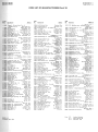
Table of Contents
TABLE OF CONTENTS
Section
I
GENERAL INFORMATION . .
1-1. Description. : . . . .
1-5. Instrument and Manual
Identification. • . . .
1-7. Accessories Available.
Page
1-1
1-1
Section
II
INSTALLATION . • . . . .
2-1. Inspection . • . . • . .
2-4. Power Requirements . . • • .
2-6. Installation
.
2-8. Repackaging For Shipment.
Page
2-1
2-1
2-1
2-1
2-1
1-1
1-1
Section
Page
OPERATING INSTRUCTIONS
3-1
3-1. Introduction . . . . . .
3-1
3-3. Front Panel Description. .
3-1
3-5. Operating Procedure. . . .
3-1
3-7. Battery Charging Information.
3-1
3-9. Instrument Temperature Limits. . 3-1
3-11. Input Protection . • . .
3-1
3-13. Voltage Measurements
.
3-1
3-18. Waveform Errors
.
3-1
3-21. Decibel Measurements
.
3-4
3-24. Impedance Correction Graph
3-4
3-27. Current Measurements . . . .
3-4
3-28.
Clip -On Probe. . . . . .
3-4
ill
Section
IV
THEORY OF OPERATION . .
4-1. Introduction . • . . . .
4-3. Preliminary Attenuator .
4-6. Input Circuit. • • . . .
4-11. Intermediate Attenuator .•
4-20. Meter Rectifier Circuit
4-25. Power Supply. . . • . . • .
Page
4-1
4-1
4-1
4-1
4-2
4-2
4-3
Section
Page
V
MAINTENANCE
.
5-1
5-1
5-1. Introduction
.
5-6. Test Instruments Required.
5-1
5-8.
Meter, Mechanical Zero.
5-1
5-2
5-10. Performance Checks
.
5-12.
Calibration Checks
.
5-2
5-13.
Frequency Response Checks.
5-2
5-16.
Noise Check
.
5-3
5-3
5-17.
Input Resistance Check. .
5-18. Adjustment and Calibration
5-3
Procedures. . . . . . . . .
5-20.
Power Supply Adjustment
5-3
5-4
5-21.
Input Resistance . . . . .
5-4
5-23.
Overload Check. . .
5-24.
Calibration and Tracking.
5-4
5-25.
High Frequency Response
5-5
5-26.
30-Volt Response Calibration . 5-5
5-27. Troubleshooting . . . . . . . . . . 5-5 5-29. Repair. . • . . . . . . . . . . . . . 5-6
5-30.
Cabinet Removal
. 5-6
5-31.
Servicing Etched Circuit Boards 5-6
5-7
5-33.
Transistor Replacement
.
5-35.
Function Switch Repair
. 5-7
5-37.
Fluorescent Indicator Decal.
5-7
Section
VI
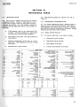
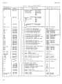
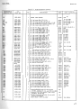
REPLACEABLE PARTS . .
6-1. Introduction.......
6-4. Ordering Information. .
6-6. Non-Listed Parts. . .
Page
6-1
6-1
6-1
6-1
Appendix
A
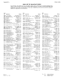
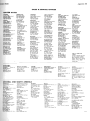
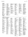
CODE LIST OF MANUFACTURERS
B
SALES AND SERVICE OFFICES
C
MANUAL BACKDATING CHANGES
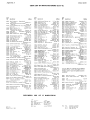
LIST OF TABLES
Number
Page
1-1. Specifications. . . . . . • . . . . . .
. 1-1
1-2. Accessories Available . • . . . • • . . .• 1-2
3-1. Effect of Harmonics on Model 403B
3-4
Voltage Measurements • . • • • • .
3-2. Examples of Voltage and DB Measurements. 3-4
5-1. Test Instruments Required. . . . . • . . • 5-1
Number
5-2. Calibration Check Table. . . . . . .
5-3. Troubleshooting. . . . . . . . . .
5-4. Test Procedure Troublesliooting .
5-5. Transistor Replacement.
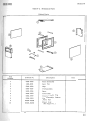
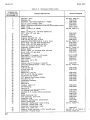
6-1. Replaceable Parts.
6-2. Mechanical Parts
Page
5-2
5-6
5-6
5-7
6-2
6-5
LIST OF ILLUSTRATIONS
Number
Page
1-1. Model 403B Transistorized AC
Voltmeter. • . . . . . . .
. . . . . . 1-0
3-1. Front Panel Description . . . . • . . . . . 3-2
3-2. Voltage Measurements. . . . • . . . . . . 3-3
3-3. Model403Blmpedance Correction Graph . . 3-5
4-1. Model403BFunctionaiBIockDiagram . • . 4-0
4-2. Input Amplifier. . . • . • . . . . . . . . 4-1
4-3. Diode Current Vs Diode Voltage
4-2
4-4. Fixed Amplifier Block Diagram. . .
. 4-2
4-5. Meter Rectifier, Simplified Diagram . . . 4-3
Number
Page
4-3
4-6. Meter Rectifier Circuit.
5-0
5-1. Model 403B Top View.
5-2
5-2. Model 403B Bottom View
5-3. Overload Check Setup . . . • ••••.
5-4
5-4
5-4. Performance Check Setup. .
5-5
5-5. Frequency Response Setup
5-6. Range SWitch Detail . . .
. • • •• 5-8
5-7. Function Switch Detail. •
5-9/5-10
5-8. Schematic Diagram
5-9/5-10
. . . . . 6-7
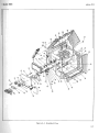
6-1. Exploded View
.
iii
Sect ion I
Mod el40 3B
8
J
\
\.\
I
'>'
\
,\\;)
r
~
I
1
\
-s
,
./
:x
,
I
OECI8HS
'''1100
~/
"HI
RANGE
VOLn
oe
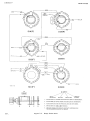
Mod el 403B Ac Vol tme ter
stan dard
Mod el 403B Ac Vol tme ter
Opti on 01
tme ter
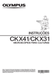
Figu re 1-1. Mod el 403B Ac Vol
1-0
Section I
Model403B
SECTION
GENERAL
1-1.
INFORMATION
DESCRIPTION.
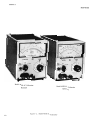
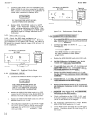
1-2. The -hp- Model 403B Transistorized AC Voltmeter is a general purpose instrument that measures
rms values of ac voltages in the 5 Hz to 2 MHz range.
The instrument has full-scale ranges from 1 mV to
300 volts (-72 dBmto+52dBm) in a 1,3,10 sequence.
The Model 403B meter face is calibrated with the upper
scale in volts (rms); the Model 403B Option 01 meter
face is calibrated with the upper scale in dB. Models
403B and 403B Option 01 are shown in Figure 1-1, and
specifications are given in Table 1-1.
1-3. The Model403B operates from Nickel Cadmium
batteries. The instrument also includes a self-contained battery charger which operates on 115 or 230
volts ac.
1-5.
INSTRUMENT AND MANUAL
IDENTIFICATION.
1-6. Hewlett-Packard uses a two-section serial number. If the first section (serial prefix) of the serial
number on your instrument does not agree with those
Table 1-1.
RANGE:
O. 001 to 300 volts rms full scale (12 ranges) in a
1, 3, 10 sequence.
FREQUENCY RANGE:
5 Hz to 2 MHz
MODEL 403B ACCURACY SPECIFICATION
o to
50 0 C
o to
-20 oC
10 Hz to 1 MHz
±2%
±8%
5 to 10 Hz
and
1 to 2 MHz
±5%
±8%
MODEL 403B OPTION 01 ACCURACY SPECIFICATION
Frequency
on the title page of this manual, change sheets supplied with the manual will define the differences between your instrument and the Model 403B described
in this manual. Some serial numbers may have a letter separating the two sections of the number. This
letter indicates the country in which the instrument
was manufactured.
1-7.
ACCESSORIES AVAILABLE.
1-8. To increase the usefulness of your instrument,
the following accessories are available:
a.
-hp- Model 11005A Line Bridging Transformer.
b.
-hp- Model 11039A Capacitive Voltage
Divider.
c.
-hp- Model 10111A BNC-To-Binding Post
Adapter.
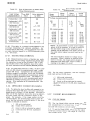
1-9. Table 1-2 provides information and use of the
accessories mentioned above as well as other useful
accessories.
Specifications
NOMINAL INPUT IMPEDANCE:
2 megohms; shunted by < 60 pF on O. 001-volt
to O. 03-volt ranges, < 30 pF on O. 1-volt to
300-volt ranges.
OVERLOAD PROTECTION:
Fuse protected:
ACCURACY:
% of Full Scale.
Frequency
I
o to 500 C
o to -20 o c
10 Hz to 1 MHz
±0.2 dB
±0.7 dB
5 to 10 Hz
and
1 to 2 MHz
±0.4 dB
±0.7 dB
METER:
Individually calibrated, taut band. Responds to
average value of input waveform and is calibrated
in the rms value of a sine wave.
DC ISOLATION:
Signal ground may be ±500 Vdc from external
chassis.
POWER SUPPLY:
4 rechargeable batteries (furnished). 40-hour
operation per recharge (20 hours at -20 0 C), up
to 500 recharging cycles (expected battery life of
20,000 hours). Recharging circuit is self-contained and functions automatically when instrument is operated from ac line (115 or 230V ±10%
48 to 440 Hz, < 3 watts).
TEMPERATURE RANGE:
-20 o C to +50 o C.
DIMENSIONS:
5-1/8 in. wide, 6-3/32 in. high, 8 in. deep.
ACCESSORIES AVAILABLE:
-hp- 11002A Test Leads, 5 ft. long, dual banana
plug to alligator clips. -hp- 11003A Test Leads,
5 ft. long, dual banana plug to probe and alligator
clip.
ACCESSORY FURNISHED:
Detachable power cord.
1-1
Model403B
Section I
Table 1-2. Accessories Available
Model No.
Use
Features
11002A
11003A
Test Leads
Dual Banana Plug to Alligator Clips
Dual Banana Plug to Probe and Alligator Clip
1l01lA
Adapter
Binding Post to BNC
1l005A
Line Bridging Transformer
Provides balanced 600 -ohm input
to unbalanced 600-ohm output for
measurements on balanced lines.
Terminating Resistance: 600 or 10 K ohms
Frequency Range:
20 Hz to 45 kHz
Power Handling Capacity: +15 dBm (4.5 V into 600n)
1l039A
Capacitive Voltage Divider
(Division ratio: 1000:1)
Accuracy:
±3%
Input Capacity:
15 pF ± 1 pF
60 Hz 25 kV, 100 kHz
Max. Voltage Rating:
22 kV, 1 MHz 20 kV, 10 MHz 15 kV, 20 MHz 7 kV
456A
AC Current Probe
1 mY/rnA ±1% at 1 kHz
Resistance
Max. Current
Accuracy
< 50 milliohms
1 amp rms
1. 5 amp peak
±2%
100 Hz to 3 MHz
11004A
1-2
Line Matching Transformer
Provides balanced 135 or 600 ohm
input to 600 ohm unbalanced output for measurements on balanced
lines.
Terminating Resistance: 600 or 10 K ohms
5 kHz to 600 kHz
Frequency Range:
Power Handling Capacity: 22 dBm (10 V into 600 n)
Model403B
section II
SECTION II
INSTALLATION
2-1.
INSPECTION.
2-8. REPACKAGING FOR SHIPMENT.
------NOTE - - - - -
2-2. Unpack the instrument upon receipt and inspect
it for signs of physical damage such as scratched
panel knobs etc. If there is any apparent damage,
file a claim with the carrier and refer to the warranty
page on the back side of the front cover of this manual.
If the instrument is to be shipped to
Hewlett-Packard for service or repair, attach a tag to the instrument
identifying the owner and indicating
the service or repair to be accomplished; include the model number
and full serial number ofthe instrument. In any correspondence, identify the instrument by model number,
serial number and serial number
prefix.
2-3. An electrical inspection should be performed as
soon as possible after receipt. To aid in electrical
inspection, performance checks are included in section V, Paragraph 5-10.
2-4.
POWER REQUIREMENTS.
2-5. The ac power circuit which provides charging
current tothe Nickel-Cadmium batteries in the instrument can be connected to a 115- or 230- volt, 48 - 440·
Hz, source. A switch located on the rear panel of
the instrument allows the user to select 115- or 230volt modes of operation.'
I WARNING I
WHEN THE 403B IS USED WITHOUT
THE POWER CORD, THERE IS NO
GROUND RETURN. USE CAUTION
TO AVOID ELECTRICAL SHOCK.
2-6. INSTALLATION.
2-7. The -hp- Model 403B is fully transistorized;
therefore no special cooling is required. However,
the instrument should not be operated where the ambient temperature exceeds 50 0 C (131 0 F).
2 -9. The following is a general guide for repacking
for shipment. If you have any questions, contact your
local -hp- Sales and service Office. (see Appendix B
for office locations.)
a.
Place instrument in original container if available. If original container is not available,
one can be purchased from your nearest -hpSales and service Office.
If original container is not used,
b.
Wrap instrument in heavy paper or plastic before placing in an inner container.
c.
Use plenty of packing material around all sides
of instrument and protect panel faces with cardboard strips.
d.
Place instrument and inner container in a heavy
carton or wooden box and seal with strong
tape or metal bands.
e.
Mark shipping container with 'Delicate Instrument, " "Fra~ile" etc.
2-1
Model403B
section ill
SECTION III
OPERATING INSTRUCTIONS
3-1.
INTRODUCTION.
3-2. This voltmeter is ready for use upon receipt
from the factory and will give specified performance
after a short warm-up period. Allow approximately
60 seconds warm-up for optimum performance.
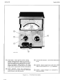
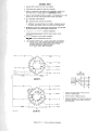
3-3.
FRONT PANEL DESCRIPTION.
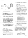
3-4. A description of front panel controls is given in
Figure 3-1. The descriptions are keyed to the photo
that accompanies the figure.
3-5.
BATTERY CHARGING INFORMATION.
3-8. The 403B has a self-contained battery charger.
This instrument is continually charging the batteries
whenever the FUNCTION switch is ON and the line
cord connected to a 115 or 230 volt source. In the
event of complete discharge, the 403B can be used
after twenty minutes of recharging with the line cord
connected to an ac source. Complete recharge requires
approximately 60 hours (depending on setting of R39)
when the Nickel Cadmium cells are completely discharged. (Refer to Section IV, Paragraph 4-25).
THE FOUR NICKEL CADMIUM BATTERIES IN THE -HP- 403B ARE IN
HERMETICALLY-SEALED CONTAINERS. UNDER HIGH TEMPERATURES
(ABOVE 50 0 C), HYDROGEN IN THE
HERMETICALLY -SEALED BATTERY
CONTAINER CAN BUIlD UP TO LARGE
PRESSURE, CAUSING DAMAGE TO THE
BATTERIES AND/OR INSTRUMENT.
(REFER TO SECTION IV, PAGE 4-3.)
3-9.
3-11.
INPUT PROTECTION.
3-12. A 1/16 A fuse is included in series with the
input Circuit which will open with repeated or excessive overload. This fuse is accessible when the cabinet is removed. A spare fuse is included inside the
instrument.
3-13.
VOLTAGE MEASUREMENTS.
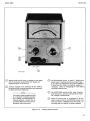
OPERATING PROCEDURE.
3-6. The operating procedure for the Model 403B is
given in Figure 3-2. Instructions are keyed to the
photo that accompanies the figure.
3-7.
at temperatures below OOC, be certain the batteries
are fully charged prior to subjecting instrument to
this temperature.
INSTRUMENT TEMPERATURE LIMITS.
3-10. This instrument has certain temperature limitations. The design of this instrument has provided
for safe and stable operation over the range of -20 to
+50 o C (-4 to +131 0 F). This temperature range is
quite adequate for most users; however, keep these
limits in mind when operating under field conditions.
Internal temperatures in excess of 122 0 F are quite
easy to obtain if the instrument is left in the sun, even
if the air temperature is quite moderate. A good
practice is to be certain that the instrument is not
stored or operated in direct sunlight to avoid the possibility of reduced performance. When using 403B
3-14. Always leave the instrument onthe1-voltrange
or higher when making initial connections to circuits
which have dc levels over 25 volts. Then switch to
the appropriate lower range to obtain an up-scale
reading. This practice should be used when making
power supply ripple measurements where the dc voltage may be as much as 600 volts, but the ac ripple is
only a few millivolts. To obtain specified accuracy,
the ground strap should be connected except when
the signal ground is dc offset from chassis ground.
3-15. If measurements are made from a high-impedance source, hum pick-up can affect the meter indication because of high impedance of both the source
and voltmeter. Shielded leads will reduce pick-up
although they will cause an increase in the capacity
shunted across the source, with the possibility of
excessive circuit loading.
3-16. The rated 2 megohms input resistance will be
effectively reduced (above 1 kHz) by shunt input capacity. (This fact is true for any ac voltmeter.) 50 pF
has a reactance of 0.8 megohm at 4 kHz, 80,000 ohms
at 40 kHz, etc. The shunt capacity decreases on the
higher ranges (see Table 1-1). This factor should be
considered when measuring higher frequency voltages
in circuits of moderate impedance level.
3-17 . severe RF circulating currents are generated
at potentials approaching 300 volts in the 1 to 2 MHz
frequency range. These severe ground currents limit
the accuracy of the 403Bto±10% on the 300-volt range.
By using -hp- accessories 1000lA (10:1 divider) and
a 10111A (adapter) shunted by a 2-megohm resistor,
the accuracy of the 403B can be retained to ±5%.
3-18.
WAVEFORM ERRORS.
3-19. In order to maintain accuracy of measurement, one must remember that this instrument is an
average responding device, but the meter scale is
calibrated in terms of the rms value of a pure sine
wave. If the waveform of the voltage being measured
contains appreciable harmonics or other spurious
voltages, the meter indication will deviate from the
true rms value on the order indicated by Table 3-1.
3-1
section
m
Mode1403B
.Ull lilt
FUNCTION: Three-position switch checks
CD battery
charge when the switch is in the ON
Fluorescent Iooicator: Glows when instrument
is on.
position; it applies 27. 5 volts from the NickelCadmium batteries to the Mode1403B circuitry.
When in the BATT. TESf position, the meter
should read above 2.4 volts on the "0-3" meter
scale, which is equivalent to 24 Vdc at the battery.
BATT. CHARGE: Glows when instrument is
CD connected
to an AC source with the FUNCTION
switch turned to the ON position.
Figure 3-1.
3-2
RANGE: selects range from 0.001 volt to 300
volts rms full scale in a 1, 3, 10 sequence.
CD
INPUT: Connect voltage to be measured to
these terminals.
Front Panel Description
Section
Model403B
m
4058-A-IIIZA
o
Select range which gives a reading in the upper
2/3 of the meter scale (This will insure the
highest degree of accuracy).
CD terminals
Connect voltage to be measured at the INPUT
(red terminal positive and unground-
Set FUNCTION switch to BATT. TEsr; front
panel meter reading should be greater than
2.4 volts (corresponds to 24 volts at battery).
If less than 2.4 volts, the battery needs recharging. Refer to Paragraph 3-7 for battery
charging instructions.
ed black terminal negative).
----NOTE----The outer black ground terminal
is connected to chassis ground.
For voltage measurements at
chassis ground, connect the ungrounded black terminal to the
grounded black terminal.
Set FUNCTION switch to ON; lamp function
knob will glow, and the instrument is ready
for voltage measurement.
When the instrument is connected to an AC
power source and the FUNCTION switch is to
ON, the BATT. CHARGE lamp will glow, indicating that the battery is being charged.
Figure 3-2. Voltage Measurements
3-3
Section ill
Model403B
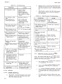
Table 3-1.
Table 3-2.
Effect of Harmonics on Model 403B
Voltage Measurements
Input Voltage
Characteristics
True RMS
Value
Value Indicated
by 403B
Examples of Voltage and DB
Measurements
Meter
Scale
Range
Switch
Fundamental = 100
100
100
Voltage measurements:
Fundamental +10%
2nd harmonic
100.5
100
300
10
Fundamental +20%
2nd harmonic
102
100 - 102
Fundamental +50%
2nd harmonic
112
100 - 110
Fundamental +10%
3rd harmonic
100.5
96 - 104
Fundamental +20%
3rd harmonic
102
94 - 108
Fundamental +50%
3rd harmonic
112
90 - 116
3-20. This table is a general one and applies to any
average responding rms calibrated voltmeter. As
can be seen in the table, errors are small even with
a badly distorted signal (e. g.; 20% 2nd harmonic gives
+0, -2% error).
3-21.
DECIBEL MEASUREMENTS.
3-22. Measurements in terms of decibels are made
in the same way as voltage measurements except that
the indication is read on the dB scale (-12 to +2 dB).
The decibel level is the algebraic sum of the meter
dB scale indication and DB VOLTS (RANGE) position.
3-23. To read power directly in dBm, (0 dBm=l milliwatt into 600 ohms) the mE;asurement must be made
across 600 ohms. Comparative dB measurements
(without respect to reference level) may be obtained
by direct reading provided each measurement is made
across the same impedance value. The difference in
decibels between two or more measurements may be
obtained by reading directly from the dB-scale indications. (For examples of dB measurements, refer
to Table 3-2.)
3-24.
3-4
.003
.001
+ 1
+30
(dB-scale indication)
(range switch position)
+31
+ 8
(level in dB as indicated by meter)
(correction for 90-ohm impedance)
+39
dBm
1.8
0.44
2.3
.27
Actual
Level
180
4.4
.0023
.00027
DB measurements:
+40
+40
+10
-30
-30
*-50
-60
dB
dB
dB
dB
dB
dB
dB
dB
dB
dB
dB
dB
dB
dB
+2 dB
-7 dB
-6 dB
o dB
-8 dB
-9 dB
+1 dB
+42
+33
+ 4
-30
-38
-59
-59
dB
dB
dB
dB
dB
dB
dB
*NOTE: In cases where a meter scale reading
below -8 dB is obtained, it is best to switch to
the next lower range on the instrument so a
reading will be obtained in the upper portion of
the scale where highest accuracy may be obtained.
The same situation exists for voltage measurements. When a reading is obtained in the
lower 1/3 scale, the range switch should be
switched to the next lower range to obtain a
reading in the upper 2/3 scale.
3-26. For the same conditions, with the measurement made across 10,000 ohms:
+ 1
+30
(dB-scale indication)
(range switch position)
+31 (level in dB as indicated by meter)
-12.5 (correction for 10,OOO-ohm impedance)
+18.5dBm
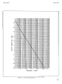
IMPEDANCE CORRECTION GRAPH.
3-25. To obtain the level in dBm with respect to impedances other than 600 ohms, the meter correction.
graph shown in Figure 3-3 may be'Used. The level In
dBm will be the algebraic sum of the level as indicated on the meter and the correction shown on the
graph. For example, if the range switch is at the
+30 dB position, the measurement made across 90
ohms, and the indication ontheDB scale +1, the level
in dBm is obtained as follows:
3
1
3
1
Meter
Indicates
3-27.
3-28.
CURRENT MEASUREMENTS.
CLIP-ON PROBE.
3-29. The -hp- Model 456A Current Probe provides
quick measurement of current from 1 rnA to 1 amp
full scale with minimum circuit loading.
3-33. To use the Model 456A, simply clamp the probe
around the current carrying wire and plug the output
into the Model 403B. The probe output is 1 mV/mA.
Section III
Model403B
+20
+15
~
OJ
+10
0
I
Z
0
+5
~
U
W
a:
a:
0
u
0
a:
w
~
W
~
-5
-10
-15
-20
-25
I
10
100
IK
10K
lOOK
IMPEDANCE - OHMS
Figure 3-3. Model 403B Impedance Correction Graph
3-5
~
I
o
INPUT
IMV-300V
~Ol
0.3
0.1
.03
.01
.003
.001
:
I
~
2
I
I
4
2
I
I
"
I
I
L
I
I
I
,
I
12
300
I
,
I
,
II
~
100
I
I
I
,
I
I
I
~
r::fo==:::=:::~-;.:::::::=;:::~
I
I
I
r
r-------------"1
I
,.--
1
12
"
'0
9
4
2
,
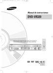
Figure 4-1. Model 403B Functional Block Diagram
POSTIVE
~ AC FEEDBACK
+
SI
RANGE
SWITCH
l
D.~ F
NEGATIVE AC FE
( , NEGATIVE
Model403B
Section IV
SECTION IV
THEORY OF OPERATION
4-1. INTRODUCTION.
4-6. INPUT CIRCUIT.
4-2. The Model403B includes a preliminary input
attenuator, a high impedance emitter follower circuit, a range attenuator and a wide range fixed gain
amplifier. Refer to Figure 4-1.
4-7. Rll, CR1, and CR2 make up a limiting circuit
which is used for overload protection to prevent high
instantaneous voltages from being impressed on the
base of Q1. F1 is a 1/16 amp fuse used to protect
the 403B against a continuous or repeated overload.
4-3.
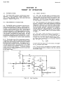
4-8. Since transistors are inherently low impedance
devices, a need for a high input impedance is required.
Referring to Figure 4-2, it would seem that the input
resistance of the first stage would be approximately
Ri of a grounded collector configuration in parallel
with R9, plus the R7-RB combination. Q1 and Q2 ~e
emitter followers, exhibiting unity gain and no phase
reversal. (Ri = approx. input Z of a common collector stage.)
PRELIMINARY ATTENUATOR.
4-4. The RANGE switch is divided up into two sections: the preliminary attenuator, located between
the input terminals and Q1, and the intermediate attenuator, located between Q2 and Q3. The preliminary
input attenuator has two ranges, 100:1 and 10,000:1,
which are switched in at the appropriate time to keep
the input voltage to Q1 less than O. 030 volt. This not
only prevents overloading the input system, but also
provides the necessary accurate attenuation to work
with the intermediate attenuator to produce the conventional 1, 3, 10 sequence for correct meter operation.
4-5. The attenuators are of the compensated resistorcapacitor (rc) type, with the capacitive division ratio
made equal to the resistive ratio to maintain a constant
division ratio at all frequencies. By making one of
the capacitors adjustable, the small variations in stray
circuit capacity can be compensated for, so the voltmeter will have a flat response. The exact division
ratio is set at low audio frequencies by the trimmer
potentiometers, which bring the resistor division ratio
to the exact value.
4-9. The output of Q2 is fed back to the junction of
R9 and R7 -R8. There is an ac voltage existing at this
point that is very nearly the same amplitude as, and
in phase with, the input voltage. Since a very small
ac voltage exists across R9 (due to the feedback from
Q2), the input current lin will be very small. Thereby:
Zin
=
E in
~
10
It can be seen that when lin is very small, the appar-
ent Zin becomes very large.
4-10. The Ri of Q1 is increased in a similar manner
by feeding the Q2 emitter voltage to both the collector
and emitter of Q1.
-13V
R7
C9
+
-13V
CIO
02
RI5
+
~
-S-POSITIVE
FEEDBACK
~
+
~EOUT
RIG
CI2
Figure 4-2. Input Amplifier
4-1
Section IV
4-11.
Mode1403B
INTERMEDIATE ATTENUATOR.
4-12. The output of Q2 is fed to the intermediate section of the range attenuator. The range attenuator is
a voltage divider, in sequence with the preliminary
attenuator. A (1, 3, 10 etc.) ratio is obtained resulting in 10 DB steps. Refer to Figure 4-1.
4-13. Refer to schematic diagram (Figure 5-8) in
the back of this manual.
~I
/
/
4-14. Transistors Q3 through Q6 make up the fixed
gain amplifier which is used to develop the current
for (full scale) meter deflection and to provide the
meter circuit with a high impedance source for linear
operation at all current levels.
4-15. The output of the intermediate range attenuator
is fed to the base of Q3 (djfferential amplifier), and
compared with a feedback signal to its emitter from
the meter circuit. This difference signal is fed to Q4
which in turn is directly coupled to Q5 and Q6. Q4 is
a grounded emitter amplifier. Q5 is a common collector amplifier which impedance matches Q6, a common base amplifier. The direct couple feature of the
amplifiers is necessary because of the low-frequency
(5 hertz) response of the 403B. R24 through R26 make
up the dc feedback loop which tends to minimize any
tendency for dc drift due to ambient temperature
change. R33 corrects the total gain of Q3 through Q6.
/
o
/
V
/
0.6
V
VOLTAGE INCREASING----•• RO
DIODE
VOLTAGE (Ed)
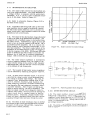
Figure 4-3. Diode Current Vs Diode Voltage
4-16. The meter source impedance is increased by
the use of negative feedback from the output of the
meter rectifier bridge to the emitter of Q3. Resistor
R28 through R30, and C15 and C16 correct the phase
of the feedback at high frequ~ncies.
_ _ _ NEGATIVE D.C.
FEEDBACK
RZ4
C20
T
4-17. The necessity of high meter source impedance
can be understood by referring to Figures 4-3 and 4-4.
4-18. To have correct voltmeter action, it is necessary that the change in meter circuit be proportional
to a change in amplifier input voltage. The load resistance, then, should remain constant. Note in Figure 4-3, however, that when 10 (and therefore the
diode voltage Ed) decreases, the diode resistance Rei
(and therefore the load resistance) increases, affecting meter linearity. Note in Figure 4-4 that Rei appears in series with Ro ' the source impedance. The
effect on output current, due to changes in diode resistance with voltage, can be minimized by feeding the
meter circuit from a constant current or high impedance source. In this way, changes of diode resistance will have a negligible effect ,on the total current
passing through them and hence through the meter.
4-19. The effect of diode resistance change is further
minimized by Q6 current through R35 which impresses
a fixed 0.3 volt across CR3 and CR4, biasing them
close to their contact potential.
4-2
'-------------.__---iM
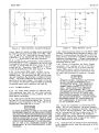
+---NEGATIVE A.t. FEEDBACK
Figure 4-4.
4-20.
Fixed Amplifier Block Diagram
METER RECTIFIER CIRCUIT.
4-21. The meter rectifier circuit is arranged in a
bridge-type configuration, with a crystal diode and a
capacitor in each branch and adc microammeter connected across its midpoints. The current through the
meter is proportional to the average value of the input voltage waveform.
4-22. The 403B meter rectifier circuit operation can
best be explained by analyzing the circuit in a simplified
Model403B
Section IV
+
R35
CR2
CRI
I
I
I
I
I
I
I
I
I
1
+
t-----------,
1
•
I
03-06
1---
I
+
+13
---,
Ro
f\.;
I
1
L ___
R36
1
1
CR4
CR3
I
1
1
Es 1
1
Rm
I
+
I
___ JI
•
I
CI9
CI7
+
+
CIS
E f TO 0 3 - - -....
'~~OA-8-0'a9
Figure 4-5. Meter Rectifier, Simplified Diagram
form. Figure 4-5 shows a voltage source generating
a voltage E s across a circuit made up of CR1, CR2,
M1, Rf, and C1, C2. Note that the current flow for
each half cycle (as imicated by the arrows) always
passes through the meter in the same direction.
4-23. In this circuit, disregarding contact potential
aM assuming zero meter resistance, the circuit could
be considered as a small resistance made up of CR1
aM CR2, in series with one capacitor (C1 + C2) in
series with Rt. Therefore, there will be a voltage
across Rf proportional to the input signal.
4-24. In the actual 403B meter rectifier circuit,
capacitors C17 and C18 provide a path for the AC
feedback loop. The generator (Q3-Q6) with its large
internal impedance (Ro) develops a voltage across the
bridge. The meter is deflected according to the average value of the input: voltage. The signal across Rt
as in Figure 4-6 provides negative feedback, resulting
in extreme linear meter operation and large Ro.
4-25.
POWER SUPPLY.
4-26. The Model 403B operates on batteries only.
This instrument uses four 6. 5 volt nickel cadmium
batteries and is designed to have a battery life of 40
hours before recharging.
4-27. R39 has been adjusted at the factory for a charging rate of 6.2 rnA to prolong battery life. If the instrument is used frequently in the field, R39 can be
adjusted for a charging rate of 11 rnA.
IF R39 IS ADJUSTED TO THE 11 rnA RATE, THE
INSTRUMENT SHOULD BE USED ON BATTERIES
ONLY EXCEPT WHEN RECHARGING BATTERIES.
THE BATTERIES ARE RECHARGED WHEN THE
403B IS CONNECTED TO AN AC SOURCE WITH
THE FUNCTION SWITCH TO ON. THE BATTERY
LIFE OF THE INSTRUMENT CAN BE PROLONGED AT THE 11 rnA CHARGING RATE IF THE
INSTRUMENT lS NOT CONTINUOUSLY OVERCHARGED.
Figure 4-6.
Meter Rectifier Circuit
4-28. When the function switch is in the BATT TEST
position, and the instrument indicates a battery voltage of 2.4 volts, recharge the batteries for 20 to 25
hours at the 6.2 rnA rate to completely recharge the
batteries in the instrument. A longer charging period
will be required if the batteries have been allowed to
discharge below 24 volts.
4-29. Figure 5-8 illustrates the Power Supply
Assembly, which supplies 4.8 rnA of current to
the instrument and 6.2 rnA of current to the batteries. R39 is used to control the amount of current used to charge the batteries and caution must
be used if R39 is adjusted to maximum charging
rate.
THE FOUR NICKEL-CADMIUM BATTERIES
IN THE 403B ARE IN HERMETICALLY
SEALED CONTAINERS. THE USER MUST
BE COGNIZANT OF TEMPERATURE EXTREMES WHILE CHARGING THE BATTERIES. UNDER HIGH TEMPERATURE
(ABOVE 50 0 CENTIGRADE), HYDROGEN IN
THE HERMETICALLY SEALED BATTERY
CONTAINER CAN BUILD UP LARGE PRESSURE CAUSING DAMAGE TO THE BATTERIES AND/OR INSTRUMENT. DO NOT CHARGE
BATTERIES ABOVE 40 0 CENTIGRADE OR
104 0 FAHRENHEIT, IF R39 IS SET ABOVE
6. 2 MA CHARGING RATE.
4-30. Figure 5-8 illustrates a conventional power
supply. For 115 volt operation, the power transformer primaries are connected in parallel, and in series
when used for 230 volt operation. The rectifier circuit is a conventional full wave bridge using C21 for
a filter capacitor. Diode CR9 (7 volt breakdown
diode) am Q7 make up the Constant Current Generator.
The collector current of Q7 is equal to the voltage
across CR9 divided by R37 and R39.
4-31. CR10 prevents the batteries from discharging
to the charging circuit when the instrument is in the
OFF position.
4-3
Model403B
Section V
METER METER
(-)
(+)
-13V -6.5V
t
l3V
CI6
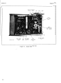
·CAL IMV
2MC
R29
METER CAL
IMV RANGE
403B-A-1333
PRE-AMPL
INPUT
SIG
GRD
PRE-AMPL
OUTPUT
R33
LOOP GAIN
ADJ
Figure 5-1. Model 403B Top View
5-0
METER AMPL
INPUT
Model403B
section V
SECTION V
MAINTENANCE
5-1. INTRODUCTION.
5-8. METER, MECHANICAL ZERO.
5-2. This section contains test and maintenance information for your 403B. Included is a quick performance check that may be made with the instrument in
its cabinet, as a part of roUtine maintenance or as a
part of incoming quality control inspection.
5-9. When the meter is properly zero-set, the
pointer will rest over the zero mark on the meter
scale when the voltmeter is 1) at normal operating
temperature, 2) in its normal operating position, and
3) turned off. Zero-set as follows to obtain best accuracy and mechanical stability.
5-3. This instrument should require very little maintenance. Should failure occur, however, a troubleshooting paragraph (5-27) has been included to assist
in locating the failure. An exploded view of the Model
403B is given in Figure 6-1 to help in locating parts.
5-4. If it becomes apparent that transistor replacement is necessary, consult Paragraph 3-33 to avoid
damage to the new transistor. Care should be taken
not to damage the printed circuit board.
5-5. Errors may be introduced in the 403B because
of the capacity added in the circuit after cabinet replacement. Therefore, after making gain or frequency
response adjustments) temporarily place covers back
on instrument and recheck the adjustment.
5-6. TEST INSTRUMENTS REQUIRED.
5-7. Table 5-1 gives the test equipment required to
check the 403B.
a.
Allow the voltmeter to operate for at least
20 minutes; this allows the meter movement
to reach normal operating temperature.
b.
Turn voltmeter off and allow 30 seconds for
all capacitors to discharge.
c.
Rotate mechanical zero-adjustment screw
CLOCKWISE.
d.
Continue to rotate adjustment screw CLOCKWISE; STOP when pointer is right on zero.
e.
Rotate adjustment screw COUNTERCLOCKWISE 15 0 to remove tension.
f.
If step e causes the meter to move off
zero, repeat procedure, making the
COUNTERCLOCKWISE rotation less than
15 0 •
Table 5-1. Test Instruments Required
INSTRUMENT TYPE
MINIMUM REQUIRED SPECIFICATIONS
RECOMMENDED
-hp- INSTRUMENTS
DC Electronic Voltmeter
sensitivity: 1 volt full scale minimum
Input resistance: 10 megohms or higher
Model 412A
Vacuum Tube Voltmeter
Voltmeter Calibration
Generator
Output voltage range: .001 to 300 volts
Signal frequency: 400 Hz
Distortion: less. than 0.2%; Accuracy
±0.25%
Model 738BR
Voltmeter Calibrator
Termination
Resistor
Resistor
Feedthrough, 50' ohm
15 kilohm ± 10%,' 10 watt
200 kilohm ± 1% ~
Model 11048B
0811-9034
0757-0128
AC Electronic Volt.meter
Input impedance: 10 megohms shunted by
25 pF (below the 0.3 volt range)
Accuracy: ±2% from 20 Hz to 1 MHz
Model 400E/EL Electronic
Voltmeter
Clip OnDC
Milliammeter
Current Range: 3 mA to 1 ampere
Accuracy: ±3% ±0.1 mA
Model 428A/B
DC Milliammeter
Oscillator
Frequency range: 5 Hz - 2 MHz
Output impedance: 600 ohms, 50 ohms
Output level: o to 1 V rms into 600 ohms
Monitor: meter circuit with expand function
Model 652A
5-1
Model403B
Section V
51
403B-A-1334
RANGE
R3
R4
Figure 5-2. Model 403B Bottom View
5-10.
5-11. The performance checks are in-cabinet tests
that compare the 403B with its specifications. These
procedures can be used bothfor incoming and periodic inspections. Refer to Table 5-1 for test equipment
required throughout this procedure.
5-12. CALIBRATION CHECKS.
a.
Connect the 403B as shown in Figure 5-4.
c.
Set the Voltmeter Calibrator for 400 Hz and
300 V rms and set the 403B to the 300 V
range.
d.
The 403B should indicate between 294 V and
306 V.
Repeat steps c and d for each voltage indicated in Table 5-2.
5-13.
Table 5-2.
FREQUENCY RESPONSE CHECKS.
300V
100V
30V
10V
3V
lV
0.3V
O.lV
30mV
10mV
3mV
lmV
5-2
MODEL 403B
INDICATION (V RMS)
Minimum
Maximum
294V
98V
29.4V
9.8V
2.94V
0.98V
0.294V
0.098V
29.4mV
9.8mV
2.94 mV
0.98 mV
306V
102V
30.6V
10.2V
3.06V
1. 02V
0.306V
0.102V
30.6 mV
10.2 mV
3.06 mV
1. 02 mV
d.
Change the 652A frequency to 500 kHz and
adjust the output level for the same reference level as in step c.
The 403B meter indication should be within
0.92 mV and 0.96 mY.
Repeat step d for 1 MHz and 2 MHz. The 403B
meter reading should be between O. 89 mV
and 0.99 mY.
5-14. HIGH FREQUENCY RESPONSE CHECK.
a.
Connect the 403B as shown in Figure 5-5.
e.
b.
Set the 652A for 400 Hz and adjust the output
level for 0.94 mV indication on 1 mV range
of the 403B meter.
f.
Place the 652A OUTPUT MONITOR switch to
EXPAND and adjust the REF SET control for
a convenient reference point.
g.
c.
Calibration Check Table
VOLTMETER
CALIBRATOR
OUTPUT (400 CPS RMS)
Rotate the 403B 'FUNCTION switch to BATT
TEST. Meter' should read 2.4 volts on the
3.0 volt scale. If 403B does not read 2.4
volts, recharge the batteries.
b.
e.
-----NOTE-----Do not adjust the REF SET control
for the remainder of the check.
PERFORMANCE CHECKS.
Repeat the same procedure for the 0.003,
0.01, 0.03, 0.1 and 3 volt range.
Mode1403B
Section V
h.
Turn the 403B RANGE switch to 30 volts.
- - - - - NOTE-------
i.
Connect an oscillator (-hp- Model 200 CD}to
the 403B INPUT. Set the frequency to 400Hz.
This corresponds to an input resistance of 1. 8 to 3. 8 megohms where:
j.
Connect on AC Voltmeter (-hp- Model 400E
E L) to the oscillator output.
k.
Adjust the oscillator for a 20. 0 volt reading
on the 403B meter. Record the reading on
the monitoring voltmeter (connected in Step j).
1.
Adjust the oscillator frequency to 300 kHz.
Adjust the oscillator AMPLITUDE control until the monitoring voltmeter indicates the reference level recorded in step k.
m. The 403B meter should indicate between 19. 4V
and 20. 6V.
5-15.
LOW FREQUENCY RESPONSE CHECK.
Rinput =
E meter
E input - E meter
-----:;::...:...;~---x
R series
5-18. ADJUSTMENT AND CALIBRATION
PROCEDURES.
5-19. The following is a complete adjustment and
calibration procedure and should be made only if it
has been definitely determined that the 403B is out of
adjustment. Transistor changes are usually not cause
for complete adjustment (see Table 5-5). If the instrument fails any of the limits given in the following
steps, carefully recheck your connections and procedure. If the instrument still fails the step, refer
to Table 5-3 and 5-4 for possible cause and corrective action.
a.
Connect the 403B as shown in Figure 5-5.
------NOTE - - - - - -
b.
Set the 652A for 400 Hz and adjust output
level for 0.94 mV indication on 1 mV range
of 403B.
In order to avoid the effects of hand
capacity, a tuning wand with a nonmetallic shank should be used for
all adjustments.
c.
Place OUTPUT MONITOR switch on 652A to
EXPAND and adjust REF SET control for a
convenient reference point.
5-20. POWER SUPPLY ADJUSTMENT.
a.
Connect the 403B to a variable line transformer. Set the line voltage to 115 volts;
turn on the AC Voltmeter, and allow five
minutes for warmup.
b.
Connect a Clip-On DC Ammeter (-hp- Model
428A/B) probe around the violet wire connected to battery BT4. Adjust R39 (see Figure 5-2) for an indication of 6: 2 mA on the
DC Ammeter.
- - - - NOTE - - - - - - Do not adjust the REF SET control
for the remainder of the check.
d.
Change the 652A frequency to 5 Hz and adjust the OUTPUT AMPLITUDE for the same
reference level as in Step c.
e.
The 403B meter indication should be between
0.89 mV and 0.99 mY.
f.
Repeat the same procedure for the 0.003,
0.01, 0.03, 0.1, and 3 volt range.
5-16.
a.
- - - - - NOTE - - - - - If the instrument is to be used
frequently in the field, R39 can be
adjusted for a fast charging rate of
11 mAo Do not charge batteries at
temperatures above 40 0 C if R39 is
set for 11 mA charging rate. Batt~ry life will be prolonged at the
lower charging rate.
NOISE CHE CK.
Disconnect the 403B from the setup shown in
Figure 5-4 and rotate the 403B FUNCTION
switch to ON.
Terminate the 403B input with a lOOK ohmshielded load. The 403B meter deflection
should be less than 3% with battery operation
and less than 8% on any range with ac operation.
5-17. INPUT RESISTANCE CHECK.
b.
a.
Connect the 403B as shown in Figure 5-4
(Position B).
b.
Rotate the 403B RANGE switch to 0.01.
c.
Adjust Voltmeter Calibrator for an output of
0.01 volt 400 Hz rms.
d.
The 403B meter should indicate between
9.0 mV and 9.5 mY.
c.
Vary the input line voltage from 103 to 127
volts; the Clip-On DC Ammeter reading
should not vary more than 1. 0 mA from the
reference setting in step b.
d.
Set line voltage to 115 volts. Using a NEMA
three prong to two prong ac adapter for isolation, connect an AC Voltmeter (-hp- Model
400E/EL) across the red (BTl) and violet
BT4} wires connected to the batteries; the
ripple voltage should not exceed 1. 5 mV.
e.
Set 403B FUNCTION switch to OFF; disconnect ac power source and set FUNCTION
switch to ON.
5-3
Model403B
Section V
f.
Connect volts probe of a DC Voltmeter (-hpModel 412A) to red wire connected to battery
BT 1; connect common lead of dc voltmeter to
violet wire connected to battery BT4.
VOLTMETER CALIBRATOR
hp738BR
o
o
DC VOLTMETER MUST BE ISOLATED FROM 403B GROUND.
o
©
oo@
o
hp403B
AC VOLTMETER
0
'--------------E:r<::::::lA
200K
:t1"4 B
g.
Rotate 403B FUNCTION switch to BATT
TEST. If DC Voltmeter reading is not 24
volts, recharge batteries in the 403B. (See
Paragraph 3-7). Adjust R45 for a 403B-meter
indication equal to voltage indicated on DC
Voltmeter.
5-22. Check the 403B input resistance by following
the procedure outlined in Paragraph 5-17. If the input resistance is not within test limits, the value of
R6 should be changed (typical range of R6 is from 3.9
to 10 megohms).
a.
Disconnectthe 403Bfrom the ac power source.
(The following procedure should be performed
with battery operation).
b.
Connect the 403B as shown in Figure 5-4
(Position A).
-----NOTE------
VOLTMETER CALIBRATOR
hp738f3R
o
hp403B
AC VOLTMETER
The 200K resistor is used only for
the input resistance check (Paragraph 5-21).
o
©
o
c.
Rotate the 403B RANGE switch to O. 001 volt.
d.
Set the Voltmeter Calibrator (-hp- Model
738BR) for 0.001 volt rms at 400 Hz.
e.
Preset R33 (loop gain adj) 1/3 clockwise am
adjust R29 (meter cal. 1 mV range) for a
full-scale imication on the 403B.
f.
Rotate the 403B RANGE switch to O. 1 volt.
Set the Voltmeter Calibrator to O. 1 volt rms
at 400 Hz.
g.
Adjust R3 (cal. 0.1 V 400 HZ) for a fullscale indication on the 403B meter.
h.
Rotate 403B RANGE switch to 30.0 volts and
set Voltmeter Calibrator to 30.0 volts at 400
Hz rms.
j.
Adjust R4 (see Figure 5-2) for a full-scale
indication on the 403B meter.
k.
Check calibration on the 0.003, 0.01, and
0.03 volt ranges; accuracy should be within
±2.0% of full scale on all ranges.
m.
Set Voltmeter Calibrator for 1. 0 volt. Rotate
403B FUNCTION switch to 1. 0 volt.
n.
Check 403B meter tracking at O. 1 volt increments. Variation should be less than ±2% of
full scale.
/
Figure 5-3. Overload Check Setup
5-23. OVERLOAD CHECK.
a.
Connect the 403B as shown in Figure 5-3.
THE 15KQ RESISTOR MUST BE
CONNE CTED AS SHOWN IN FIGURE 5-3 TO PREVENT DAMAGE
TO VOLTMETER CALIBRATOR.
5-4
Performance Check Setup
5-24. CALIBRATION AND TRACKING.
5-21. INPUT RESISTANCE.
o
Figure 5-4.
b.
Rotate the 403B FUNCTION switch to OFF;
connect anAC Voltmeter (-hp-ModeI400E/EL)
between the base of Q1 and chassis ground.
c.
Rotate the 403B FUNCTION switch to ON and
RANGE switch to 0.1 volt.
d.
Set Voltmeter 'Calibrator C,·hp-Model 738BR)
OUTPUT SELECTOR to 400Hz rms and 300
volts; the AC Voltmeter reading should be
less than 3.5 volts. (If necessary, check
CR1 and CR2).
Model403B
section V
hp403B
AC VOLTMETER
TEST OSCILLATOR
n.
Change the 652A frequency to 300 kHz while
maintaining reference on meter.
p.
Adjust C2 for a O. 96 of full scale reading on
the 403B meter.
hp652A
5-26.
a.
c.
Connect anAC Voltmeter (-hp-ModeI400E/EL)
to the Oscillator OUTPUT.
d.
Adjust the Oscillator AMPLITUDE for 9.40
volt indication on the 403B meter. Record
the AC Voltmeter (-hp- Model 400E/EL)
reading.
e.
set the oscillator frequency to 300 kHz. Adjust the Oscillator AMPLITUDE control until
the AC Voltmeter indicates the reference
level recorded in step d. The 403B should indicate 9.2 to 9.6 volts.
Figure 5-5. Frequency Response setup
5-25. mGH FREQUENCY RESPONSE.
a.
Connect the 403B as shown in Figure 5-5.
b.
set oscillator (-hp- Model 652A) to 1 mV
rms range at 400 Hz.
c.
Adjust OUTPUT AMPLITUDE control for
reading of 0.94 mV on the 403B.
d.
Place OUTPUT MONITOR switch to expand
and adjust REF SET for a convenient reference point on 652A meter.
e.
Vary the 652A frequency dial between 1 MHz
and 3 MHz keeping the same reference point
as in step d. Adjust C16 (cal. 1 mV 2 MHz)
for O. 94 mV ±5% frequency response between
1 and 2 MHz with a gradual roll-off between 2
and 3 MHz. If C16 does not have sufticient
range, the value of C15 should be cIlanged
(range of C15 is from 100 pF to 160 pF).
f.
Adjust 652A Oscillator for a 300 kHz output
frequency and same output level as in step d.
g.
Rotate 652A frequency dial between 300 kHz
and 1 MHz while maintaining same reference
on meter. The 403B meter should indicate
0.9 mV ±O. 02 mV (±2%). If necessary, adjust R33 for a flat response.
-----NOTE - - - - - Repeat Paragraphs 5-24 and 5-25
if R33 is adjusted.
h.
Rotate the 403B RANGE switch to O. 1.
j.
set the 652A Oscillator for 400 Hz and O. 1
RANGE.
k.
Adjust the OUTPUT AMPLITUDE control for
an indication of 0.96 of full scale on the 403B
meter.
m. Readjust the 652A OUTPUT AMPLITUDE
control for a convenient reference on the
652A meter.
Turn the 403B RANGE switch to the 10 V
RANGE.
Connect Wide Range Oscillator (-hp- Model
200CD) to the 403B INPUT. set the Oscillator
frequency to 400 Hz.
50n FEEO-THRU
TERMINATION
hpll048B
4038-8-1324
10 VOLT RESPONSE CALIBRATION.
-----NOTE-----The AC Voltmeter used in this
procedure should have been recently calibrated and have a known
frequency response from 400 Hz to
at least 300 kHz. If there is a variation in response between 400 Hz
and 300 kHz, this should be considered when adjusting the 403B.
f.
Adjust C3 for a403B meter indication of 10.0
volts.
g.
Repeat Paragraph 5-25, steps h thru p, adjusting C2 and C3 for optimum performance
between 0.1 volt range at 300 kHz and 10
volt range at 300 kHz.
5-27. TROUBLESHOOTING.
5-28. To assist introubleshooting, Tables 5-3 and5-4
are included in this section of the manual. Table 5-3,
Troubleshooting, is used for evaluating problems
that may be encountered and easily recognized by the
operator, and therefore consists mainly of frontpanel inlications. Tables 5-3 and 5-4. Test Procedure Troubleshooting, is for the technician to localize
areas of trouble encountered while testing the
Mode1403B.
- - - - - NOTE - - - - - When replacing any crystal diodes
or transistors in the Model 403B,
refer to Paragraph 5-33 and Table
5-5.
5-5
section V
Model403B
Table 5-3.
Troubleshooting
SYMPTOM
b.
Bottom Cover: remove the flat head screw
holding the cover to the rear panel and slide
the cover toward the rear. The bail must be
up.
c.
Side Covers: remove the flat head screws
which hold the cover to the side casting of
the instrument.
CAUSE
No response to input
Fuse F 1 blown
Batteries low
Shorted transistor
CR1 or CR2 shorted
Open contacts in range
switch
Table 5-4.
Recharge Batteries
Low reading on Batt.
test
Noise indication on
known quiet source
CR1 or CR2 noisy
Noisy transistors
(usually Q1 or Q2)
CR3 or CR4
Meter pins when switching through ranges
Dirty contacts in range
switch
C7, C12, or C13 leaky
Meter pulsates at frequencies below 15 Hz
C17, 18, 20 open or leaky
Meter calibration off on
ranges above 0.03
Resistors or capacitors
bad in range switch
Meter calibration off on
ranges below 0.1
Resistors bad in intermediate attenuator
Dirty contacts in range
switch
Battery will not hold
charge
CR10 shorted
Shorted cell in battery
Battery charge inoperative
Q7, CR5, CR6, CR7,
CR8, CR9, C21
Switch on 230V position
when using 115V
Test Procedure Troubleshooting
SYMPTOM
CAUSE
R29 will not adjust for
full scale indication
CR1, 2
CR3, 4 bad
Q1 through Q6 bad
Noise (403B input terminated with a shielded
lOOK resistor)
Usually Q1 or Q2 noisy
Input resistance out of
specs
Q1 or Q2 bad
C9, C10, Cll, R6
Meter does not track
properly
1) Meter reads consistently above or below
all meter divisions
CR3, CR4 bad
R35 wrong value
2) Meter reads above
some but below other
divisions
Diodes CR3, CR4 bad
Meter M1 bad
Low frequency response
bad
C1, 7, 12, 13, 18-20
400D reads more than
1. 5 volts on overload
CR1 or CR2 bad
Excessive Charging Rate
R39 No Effect
Bad CR9, Q7
./
0.001, 0.1, 10 cali~ration okay but all other
ranges out of calibration at 400 Hz
Replace C13
If all ranges on 400 Hz
ChangeQ3
5-31.
calibration check out
okay except for one or
two ranges and the
stick resistors check
okay
At 3 volts 2 MHz meter
reads high
No adjustment on charging current
5-32. One double-sided and two single-sided circuit
boards are used in the Model 403B. Follow these
general rules when servicing these boards.
Shorten leads on R18.
If this doesn't fix
problem, replace R18
a.
Do not apply excessive heat to the conductor
or component being soldered.
b.
Use a toothpick or wooden splinter to clean
holes before inserting new components.
c.
To remove a damaged component, clip leads
near component; then apply heat and remove
component lead with a straight upward motion.
d.
To insure good connection between the eyelet and conductor, solder from the conductor
side.
Check for solder splashes
on backside of R39
5-29. REPAIR.
5-30.
a.
5-6
SERVICING ETCHED CIRCUIT BOARDS.
CABINET REMOVAL.
Top Cover: remove the single screw wtich
holds the cover to the rear panel and slide
the cover toward the rear.
Section V
Mode1403B
5-33. TRANSISTOR
REP~CEMENT.
5-34. Transistors can be damaged by excessive heat.
When replacing transistors on the Mode1403B printed
circuit board, use a heat sink, such as an alligator clip,
and use a low wattage soldering iron. Refer to Table 5-5
for any adjustments after replacement.
a.
Moisten the back of the decal with a piece of
tissue soaked in xylene am allow a few minutes for the adhesive to soften.
b.
Place the decal over the FUNCTION switch
shaft, adhesive side down. Position the
black area directly over the OFF line on the
Model 403B panel am press the decal firmly
against the FUNCTION switch nut.
c.
Slide a bushing or nut over the shaft so that
it will hold the decal in contact with the
FUNCTION switch nut, and allow about 20
minutes for the adhesive to dry.
d.
Remove the bushing or nut used for weighting and install the small spacer and FUNCTION switch knob.
5-35. FUNCTION SWITCH REPAIR.
5-36. Figure 5-7 gives cabling detail on Model 403B
FUNCTION switch.
5-37.
FLUORESCENT INDICATOR DECAL.
5-38. If the FUNCTION switch is removed for any
reason, the fluorescent indicator decal will have to
be replaced. This decal has a special adhesive on the
back that holds firmly against the FUNCTION switch
nut. To assure positive contact, proceed as follows:
Table 5-5. Transistor Replacement
REFERENCE
Q1, 2
FUNCTION
Q1 and Q2 work together to provide a high input impedance
(Emitter Follower)
CHE CKS OR ADJUSTMENTS
REQUIRED
REFER TO
PARAGRAPH
Check input impedance
5-17 steps a thru d
Readjust R29
5-24 steps athru e
Check noise
5-16 steps a and b
Q3, 4
Amplifier (Common emitter)
Readjust R33
5-25 steps a thru g
Q5
Amplifier (Common collector)
Readjust R33
5-25 steps a thru g
Q6
Amplifies signal (Common
base)
Readjust R33
5-25 steps a thru g
CR1, 2
Protects Q1 from overload
Recheck overload
characteristic s
5-23 steps a thru d
Check noise
5-16 steps a and b
Readjust R29
5-24 steps a thru e
Readjust R45
5-20 steps e thru g
Rectifier Diodes
Check battery charge
current
5-20 steps a and b
CR3, 4
CR5,
Meter Diodes
CR9
Zener Diode
Readjust R39
5-20 steps a and b
CR10
Isolation Diode
Check battery charge
current
5-20 steps a and b
Q7
Charging Current Regulation
Readjust R39
5-20 steps a and b
5-7
Section V
Model403B
.---------,BARE. - - - - - . .
A3C5-----,
RED
.---------2Q,
T~~~~~L-8
~--A3C2.RI
'-------:~
SIA(F)
SIA(R)
;-------------,-t--,BARE,----------------..,
FI-----,
SIB(R)
SIB(F)
,Jr-----~
A3R4.R5------~
----AICI3
403B-C-1316
SIC(F)
SID(R)
SIA(F)7
51
SWITCH~ ~CONrACT
IRANGEI
\
DESIGNATOR
SECTION
FRONT SIDE
NUMBER
1. WAFER FRONTS (F) VIEWED FROM BOTTOM FRONT OF INSTRUMENT.
2. WAFER REARS (R) VIEWED FROM BOTTOM REAR OF INSTRUMENT.
3. SlC(Rl AND SlD(F) HAVE NO SWITCHING AND ARE NOT SHOWN.
A
5-8
B
c
o
Figure 5-6.
I POSITION.
4.
SWITCH SHOWN IN 1.001/ -60
5.
CIRCLED NUMBERS G) INDICATE CONTACT POSITIONS EVEN
THOUGH SOME POSITIONS MAY BE BLANK.
Range Switch Detail
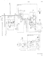
SCHEMATIC NOTES
1. RANGE SWITCH SHOWN ON 0.001 VOLT RANGE.
2.
FUNCTION SWITCH SHOWN IN THE OFF POSITION.
3.
SWITCH CONNECTIONS ARE SHOWN FOR SCHEMATIC SIMPLICITY
AND MAY NOT BE ACCOMPLISHED IN THE MANNER SHOWN.
4.
ALL DC VOLTAGES ARE TYPICAL VALUES. A TOLERANCE OF ± 10%
SHOULD BE ALLOWED WHEN MEASURING THESE VOLTAGES.
5.
W
W
DENOTES CHASSIS GROUND.
DENOTES SIGNAL GROUND (FLOATING).
*
OPTIMUM VALUE SELECTED AT FACTORY. AVERAGE VALUE
IS SHOWN AND IN SOME CASES THE PART MAY BE OMITTED.
6.
RESISTOR VALUES ARE IN OHMS AND CAPACITANCE VALUES ARE
IN MICROFARADS UNLESS OTHERWISE DESIGNATeD.
7.
--------
DENOTES ASSEMBLY.
- - - - - - - - - - - DENOTES MAIN SIGNAL PATH.
8. c==::JDENOTES FRONT PANEL MARKING.
~ DENOTES SCREWDRIVER ADJUST.
9.
~
DENOTES WIRE COLOR: COLOR CODE SAME AS RESISTOR
COLOR CODE. FIRST NUMBER IDENTIFIES BASE COLOR.
SECOND NUMBER IDENTIFIES WIDER STRIP, THIRD
NUMBER IDENTIFIES NARROWER STRIP.
(e. g. ~ = WHITE. RED. YELLOW.)
A2T1-I---J!t----...
~----~----J2
""",__- - ~ - - - R 4 5
b - - - A 2CRIO
-13V TO A I - 2
b---BTI(+)
BT4(~)----L
52
S-+13V TO AI
A2R41----.:L
IFUNCTION I
-----,BARE, - - - - - . /
S2B(F)
AICf7---~--.....
--------&, - - - BT3H
~--6.5V
(F)
(F)
A
B
TO AI
~---A2R44
1.
SWITCH WAFERS VIEWED FROM BOTTOM
FRONT OF INSTRUMENT.
2. SWITCH SHOWN IN ~ POSITION.
MI(-)----J-
~----
~----MI(+)
' - - - - - - ,BAR!:., - - f - - - - - '
4038-8-1317
'-----+--~--AICI9
S2A(F)
Figure 5-7.
Function Switch Detail
3. CIRCLED NUMBERS G) INDICATE CONTACT
POSITIONS EVEN THOUGH SOME POSITIONS
MAY BE BLANK.
Section V
Mode1403B
---------1
IRANGEI
P/O 51
0
~I~R-(~A~- - - - - - - - - - - - - - - - - - - - - - - - -
oill
o(i)
o@
I
I
-13V
o®
I
o@
00
FUNCTION
R7
34K
C9
200
R8
82K
o®
®
+
@
! ~ :r~
IINPUTI
R9
150K
®
~
F
::-....;J..I _ _""l)I~_Po/-°--o!<:JOi0;;:,1•
3
~
T:
II-Q,
I
FI
~to0liil,-C>OP/.....
0-S<lI~.1/Y'16 AMP
..
AR;IT;N~~3;-~ -
-
---'1
2M
1
[i]~11
3
I
W
C2 PF
1.5-7
CAL .IV
300KC
IRANGEI
o
:.°6°ci
ill :?~5
Q) .:~l>
@
:~~
® -~o
® ':I~
o 6
® +~o
® ~~o
@ 13<&
®
~~<&
@
;~g
I
~
0P/0 51
ill 0
Tg~OPF
Q)o
W
@o
®o
@o
00
®o
~/
I
R2
19./K
I
~
~~5 ~~~
~
02
. I,.,
C8
2
~IOPF
I
C3
1.5-7PF
CAL.,
300t<t:
0
I
I
.
~~
T
i 2bPF
I
@
I
@
W
I
AC FEEDBACK
(see Para. 4-10).
I
I
.,,/ASSEMBLY
~
I
MTO SCREWS
RI9
1081
R20
634
R2/
341.9
R22
920
R23
158.1
'\~
I
®
921
~ (f--+13V
FROM
PWR SOURCE
VIA 52
{
R34
8200
I
97
=,:,J1(f-- -13V
961
T~6=-
J
I
I
C6*r:
~I
Q)
I FUNCTION I
Ht--~+-i
P/O S2A(F)
&La
~
@
-<J
@
~
I
IQ>
16
I
I
R35
390
CAL IMV
2MC
I
MI
~
+
I
I
~03K6
l
Q)
I
__
~
;U;
._ .. -
3
L __
+_I_V
~M;L~ (403B-65;) -
R47
150
R37
300
0
~
-_-~~}....:6=3::..---O-...L.,~:!.-t- .......---4-Q)~3!'OO,...L<l>--12-
- - - - - - - - - - - - - -R44
220K
BATT
I
TEST CAL
R45
I
~ 250Kj
07
1--~20-~
I ~
R4"
I
I
ill
7
3900
Q)
BTl _
6.5V
1
WI
J2
18 I
0
(ft
I
0
Q)
ill
I
I
oill
21
:
I
IFUNCTIONI
P/O S2B(F)
...----::0--0
: 00
R42
220
@
~
~~
0
®
_---J..---
,-
I
I
~
22PF~
2 K
I,
®
I
I
~--------~
I
RI8
3419
(j)
R 4
I ~b1
RI7
1080
..=....:..:I
...---"!~
TEST~ON
12."."".} ~
-13V
I
I
I
CI2
200
~I
/;:...9
_____----+----:>-!---__
\V~o
~~
I
RIO
4700
OFF
R46
4700
-13V
R:
82M
I '
BATT.
-13V
r--------l
C7
RII
l 4. . . . .I.,..K"-........--l
~I
4
1
I RANGE I
~
ill
II
CIO
10
-13V
CRi
I
I RANGE I
I
SHORTING
STRAP
o
-13V
®
AN
ill
NEG DC
!FEEDBACf<
AC FEEDBACK
~ (see Para. 4-9)
c;=- +13V
BT2 _
A2R38
33K
I
I
6.5vl~
o
Bn _
6.5V-
I
o
ill
(i)
R41
33K
l - - - - - - - -......- -......- - - - - - - - - - . ; . - 4 o J l
403B-E-131~B
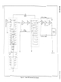
COPYRIGHT 1962 BY HEWLETT -PACKARD COMPANY
l
I
I
~-6.5V
3
o
~-------j
Figure 5-8.
Schermtic Diagram
5-9/5-10
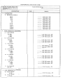
PERFORMANCE CHECK TEST CARD
Hewlett-Packard Model 403B
Transistorized AC Voltmeter
serial No.
DESCRIPTION
Tests Performed by
Date
PAR.
CHECK
l. CALIBRATION
A. RANGE ACCURACY
300V
100V
30V
10V
3V
1V
0.3V
0.1 V
0.03V
0.01 V
0.003V
0.001 V
Full
Full
Full
Full
Full
Full
Full
Full
Full
Full
Full
Full
scale
scale
scale
scale
scale
scale
scale
scale
scale
scale
scale
scale
± 2%
± 2%
± 2%
± 2%
2%
2%
2%
2%
2%
2%
2%
2%
±
±
±
±
±
±
±
±
2. HIGH FREQUENCY RESPONSE
A. 0.001 RANGE
500 kHz
1 MHz
2 MHz
0.94 Full scale ± 2%
0.94 Full scale ± 2%
0.94 Full scale ± 5%
B. 0.003 RANGE
500 kHz
1 MHz
2 MHz
O. 94 Full scale ± 2%
O. 94 Full scale ± 2%
0.94 Full scale ± 5%
C. 0.01 RANGE
500 kHz
1 MHz
2 MHz
0.94 Full scale ± 2%
0.94 Full scale ± 2%
0.94 Full scale ± 5%
D. 0.03 RANGE
500 kHz
1 MHz
2 MHz
0.94 Full scale ± 2%
0.94 Full scale ± 2%
O. 94 Full scale ± 5%
E. 0.1 RANGE
500 kHz
1 MHz
2 MHz
F.
G.
3.
0.94 Full scale ± 2%
O. 94 Full scale ± 2%
0.94 Full scale ± 5%
3 V RANGE
500 kHz
1 MHz
2 MHz
0.94 Full scale ± 2%
O. 94 Full scale ± 2%
O. 94 Full scale ± 5%
10 V RANGE
300 kHz
0.94 Full scale ± 2%
LOW FREQUENCY RESPONSE
A. 0.001 RANGE
10 cps
O. 94 Full scale ± 2%
B. 0.003 RANGE
10 cps
O. 94 Full scale ± 2%
PERFORMANCE CHECK TEST CARD (Cont'd)
Hewlett-Packard Model 403B
Transistorized AC Voltmeter
Serial No.
DESCRIPTION
Tests performed by
Date
PAR.
CHECK
3. LOW FREQUENCY RESPONSE (Cont'd)
C. 0.01 RANGE
10 Hz
0.94 Full scale ± 2%
D. 0.03 RANGE
10 Hz
E.
O~
O. 94 Full scale ± 2%
1 RANGE
10 cps
0.94 Full scale ± 2%
F. 3 RANGE
10 cps
O. 94 Full scale ± 2%
4. NOISE CHECK
A.
BATTERY OPERATION
B. AC OPERATION
5. INPUT RESISTANCE
< 3% Deflection
< 8% Deflection
9.0 to 9.5 mV
section VI
Model403B
SECTION VI
REPLACEABLE PARTS
6-1.
6-3. Miscellaneous parts are listed at the end of
Table 6-1.
INTRODUCTION.
6-2. This section contains information for ordering
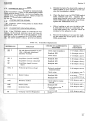
replacement parts. Table 6-1 lists parts in. alphameric order of their reference designators and indicates the description, -hp- part number of each part,
together with any applicable notes, and provides the
following:
a.
6-4. ORDERING INFORMATION.
6-5. To obtain replacement parts, address order or
inquiry to your local Hewlett-Packard Field Office.
(see Appendix B for list of office locations.) Identify
parts by their Hewlett-Packard part numbers. Include
instrument model and serial numbers.
Total quantity used in the instrument (TQ
column). The total quantity of a part is given
the first time the part nUmber appears.
6-6.
NON-LISTED PARTS.
6-7. To obtain a part that is not listed, include:
b.
c.
d.
Description of the part. (see list of abbreviations below.)
a.
Instrument model number.
Typical manufacturer of the part in a fivedigit code. (see Appendix A for list of manufacturers. )
b.
Instrument serial number.
c.
Description of the part.
Manufacturer's part number.
d.
Function and location of the part.
.sil_
eluminum
A .•...........•.............• ernpefels)
Au ............•.................. gold
Ag
AI
C ....................•....... c:epecitor
ABBREVIATIONS
Hz . . . . . . . . . . . .. hertz (cyele(s) per oecond) NPO
10
inside di
t.
impg
impnlllneted
.incendncent
incd
ins ..........•............. in..letion(ed)
cer ...................•........ .c....."ic
coef
coefficient
corn ••••••••••••••••••••••••••• COf'nlT'On
kilohm(s) - 10+3 ohms
kilohertz - 10+ 3 hertz
kn
kHz
comp ........••......•...... composition
conn
dep
OPOT
OPST
elect
connection
deposi ted
double-pole double·throw
double-pole sinllle·throw
electrolytic
encep .•...•..•...•.•••...••encepaJleted
F
.f.edls)
FET .....••......... fiald effect trensistor
fxd ........•.................... .fixed
GeAs
gellium ._ids
GHz ......•........ gigehertz - 10+9 hertz
gd ........•................•. ~.d(edl
Ge ........•................. gtrmenium
ground(ed)
end
H ................•........... henry(ies)
Hg
mercury
negetive positive ..-0
(..-0 ...".,.eture coefficient)
nenooecondls) - 10-9 seconds
not leJ*"etltly replec:eeble
ns
nsr
n
ohm(s)
~::::::::::::::::: :~.~:u~=~:
p •.••..••••...•..•••••••.•••••••• peek
l
inductor
lin .........•................ line. teper
log ....................• logerithmic teper
milliempere(s) - 10-3 _res
MHz
megehertz - 10+6 hertz
Mn
megohm(s)· 10+6 ohms
met tim
film
mlr
menufecturer
rns •...•..•..••••.•........•. millisecond
mtg
: '.'
~~nting
mV ......•........ mlillvolt(s) - 10 volts
J.IF ......•.......•.•.....•• microf.ed(s)
/.II
microsecond(s)
IN
microvolt(s) - 10-6 volts
my
Myl.®
rnA
met"
~:::::::::::::::::::::::.~=:~
12
pF
picof.ed(s) 10-
V
VIICW •••••
plo
_
¥dew
pert 01
position(s)
poly
polystyrene
pot ...........•.......... potentiometer
Pi>
peek·to-peek
ppm
peru per million
prec
precision (tempereture coeffie(lt,
long term stebility end/or toler....,.)
pol . • . • • • . • . • . • • • • • • . . • • • . . .
R
Rh
w
oect
section (s)
Si ...........•......•...........silicon
wett(s)
wiv ..............• Working in_. volt.
wlo
without
YtIW • • • • • • • • • • • • • • • • • • • • • • • • • wirewoun<:t
resistor
rhodium
s. ............................•Ienium
volt(s)
alterneting current working volteglt
v.ieble
direct current working volteglt
wI .......... .•................... with
rrTlS.•.......•.....•....• root.",.....-squ• •
rotary
'
II ide
single-pole double-throw
single-pole single-throw
Te
tentelum
TC
tempereture coefficient
Ti02
titenium dioxide
tog .........•................... toggle
to! .........•...............•. toler....,.
trim
,
trim"....
TSTR
trensistor
piv ..•................ peek in_ _ voltege
rot
nenoempere(s)-10-9 emperes
Nt::
normelly closed
neon
Ne
NO ....•........•........ normelly open
nA
f.eds
II
SPOT
SPST
.. .
.....optimum velue .I«ted at fectory,
_ . velue shown (pert mey be omitted)
no stenderd type number _gned
"ected or speciel type
®
Dupont de Nemours
DECIMAL MULTIPLIERS
....elix
Symbols
tere
T
G
M or Meg
Kor k
h
da
d
gige
rnege
kilo
hecto
deke
deci
A
8
mbly
motor
BT .................•........... bettery
C
cepecitor
CR ......•.............•........ diode
Ol
deley line
OS .......•....................... Iemp
E
mioc alectronic pert
F
','" .•........•.............. fu.
Multiplier
10 12
109
106
103
102
10
10. 1
....elix
centi
milli
micro
pico
femto
etto
Symbols
IJ.
Multiplier
10-2
10.3
10-6
10.9
10. 12
10- 15
10. 18
DESIGNATORS
Fl
filter a
transistor
HR
heater OCR
transistor-<liode
IC
integreted circuit
R
resistOf
J .....••••....•.•................ jeck
RT .............•........... thermistor
K ......•......................... relay S
.-itch
l ..............•.............. inductor T
transformer
terminer bo.d
M ..............•............... meter T8
MP ....••.....•.•....... mechenicel pert TC ......•................. thermocouple
P
plug TP .....••......••............ test point
STD-8·2734
TS
t.minel strip
U
microcircuit
V
vecuum tube, neon bulb.photocell, atc.
cellIe
W
X
lOCket
XOS
Iempholder
XF .........•............... fu.holder
Y ...•..••.•.••.......•.•.•.•.•• crystel
network
Z
.
6-1
section VI
Model403B
Table 6-1
REFERENCE
DESIGNATOR
,
-hpPART NO.
Replaceable Parts (Cont'd)
TQ
DESCRIPTION
Al
403B-65A
Assembly, printed circuit: includes,
Ql thru Q6
C7 thru C20
R6 thru R16
CRl thru CR4
R24 thru R36
R40
R46
A2
403B-65B
Assembly, resistor board: includes,
R37 thru R39
C21
CR5 thru CRI0
R41
R44
Tl
Q7
R45
R47
A3
403B-65C
Assembly, resistor board: includes,
C2 thru C5
Rl thru R5
BTl, 2, 3, 4
1420-0015
4
Battery, Nickel Cadmium 6. 5 Vnom. 225 mAh
0170-0033
1
2
1
1
1
C:
C:
C:
C:
C:
fxd O. 18 /-LF ±10% 600 vdcw
var cer 1. 5-7 pF ±10% 500 vdcw
fxd mica 820 pF ±2% 300 vdcw
fxd mica 560 pF ±2% 300 vdcw
fxd mica 22 pF ±5% 500 vdcw
Cl
C2, C3
C4
C5
*C6
0140-0151
0140-0178
0140-0145
C7
C8
C9
CI0
Cll
0160-0205
0180-0060
0180-0059
0180-0064
1
1
1
1
1
C:
C:
C:
C:
C:
fxd
fxd
fxd
fxd
fxd
C12
C13
C14
*C15
C16
0180-0104
0180-0063
0180-0039
0140-0176
0130-0017
1
1
1
1
1
C:
C:
C:
C:
C:
fxd elect 200
fxd elect 500
fxd elect 100
fxd mica 100
var cer 8-50
C17, C18
C19
C20
C21
0180-0058
0180-0033
0180-0150
0180-0149
2
1
1
1
C:
C:
C:
C:
fxd
fxd
fxd
fxd
CR1, CR2
1901-0044
2
Diode: Si 20 mA/+IV 10 mA/-I0V/50 wiv
2 pF
Diode: hybrid hot carrier
Diode: Si 100 rnA 100 wiv 2 pF
CR3, CR4
CR5 thru
CR8
CR9
CRI0
01~0-0003
0180~100
...
1901~535
2
elect
mica
elect
elect
elect
elect
elect
elect
elect
4. 7 /-L F .±10% 35 vdcw
10 pF ±5% 500 vdcw
200 /-LF +100% -10% 3 vdcw
10 /-L F 10 vdcw
35 /-LF -+,100% -10% 3 vdcw
/-LF 15 vdcw
/-LF +100% -10% 3 vdcw
/-L F 12 vdcw
pF ±2% 300 vdcw
pF 500 vdcw
50 /-LF +100% -10% 25 vdcw
50 /-L F 6 vdcw
1200 /-LF 10 vdcw
65 /-L F 60 vdcw
MFR.
MFR. PART NO.
88220
6.0V/225B
09134
72982
04062
04062
04062
Type 27
503-000-COPO-I0R
DM15F821G
DM15F561G
DM15C220J
56289
04062
56289
56289
56289
150D475X9035B2-DY~
DM15C220J
30D116Al
30D182Al
30D122Al
56289
56289
56289
04062
72982
30D174Al
30D120Al
30D154Al
56289
56289
56289
56289
30D186Al
30D133Al
Type 340
Type 30D
73293
HD
-hp':'
03877
SG-817
557-019-U2 P034R
1901-0025
5
1902-0074
1901-0025
1
Diode: breakdown 7. 15V ±5% 400 mW
Diode: Si 100 rnA 100 wiv 2 pF
07910
03877
CE 35664
SG-817
DSl
1450-0419
1
Indicator: neon
72765
599-237 white
Fl
2110-0011
1
Fuse, 1/16 amp 250 V maximum 5.4 ohm
75915
#312.062
1510-0008
1510-0009
5060-0626
0340-0090
1251-2357
3
1
1
1
1
1
Terminals: three female
Assembly binding post: red
Assembly binding post: black
Assembly binding post: black with strap
Insulator: B. P. double keyed
Connector: ac power
-hp-hp-hp-hp82389
EAC-301
Ml
1120-0315
1120-0316
1
1
Meter: 0-100 /-LA dc
Meter: 0-100 /-LA dc DB Scale (option 01)
-hp-hp-
Ql,Q2, Q3, Q5
Q4, Q6
1853-0020
1854-0071
4
2
TSTR: Si PNP
TSTR: Si NPN
01295
01295
Jl
J2
6-2
SKA1123
SKA1124
Section VI
Model403B
Table 6-1.
Replaceable Parts (Cont'd)
REFERENCE
DESIGNATOR
-hpPART NO.
TQ
Q7
1853-0016
1
TSTR: PNP 2N3638
Rl
R2
R3, R4
R5
*R6
0727-0287
0727-0443
2100-0390
0727-0056
0687-8251
1
1
1
1
1
R:
R:
R:
R:
R:
R7
R8
R9
RIO
R11
0698-4493
0758-0022
0687-1541
0687-4721
0693-1021
1
1
1
2
1
R12
R13
R14
R15
R16
0687-5621
0687-1221
0687-1531
0687-6831
0687-6821
R17
R18
R19
R20
R21
DESCRIPTION
MFR.
MFR. PART NO.
01295
2N3638
fxd comp 2M ±1% 1/2 W
fxd comp 19. lkn ±1% 1/2 W
var comp dual 2k and 6k ohms 1-1/4 W
fxd carbon flm 216 ohms ±1/2% 1/2 W
fxd comp 8. 2M ±10% 1/2 W
19701
19701
71590
19701
01121
DC 1/2 CR5
DC 1/2 CR5
Series Type 73-2
DC 1/2 AR5
EB 825J.
R:
R:
R:
R:
R:
fxd
fxd
fxd
fxd
fxd
flm 34 kn ± 1% 1/8 W
comp 82kn ±5% 1/2 W
comp 150kn ±10% 1/2 W
comp 4. 7kn ±10% 1/2 W
comp lkn ±10% 1/2 W
91637
07115
01121
01121
01121
CMF-l/I0-32 T-l
C20
EB 1541
EB4721
HB 1021
2
1
1
1
1
R:
R:
R:
R:
R:
fxd
fxd
fxd
fxd
fxd
comp
comp
comp
comp
comp
01121
01121
01121
01121
01121
EB
EB
EB
EB
EB
0727-0103
403B-26A
403B-26B
0727-0084
403B-26C
1
1
1
1
1
R:
R:
R:
R:
R:
fxd
fxd
fxd
fxd
fxd
carbon flm 1080n ±1% 1/2 W
ww 3. 41kn ±O. 2% 1/2 W
ww 1. 081kn ±O. 2% 1/2 W
carbon flm 634n ±1% 1/2 W
ww 341. 9n ±O. 2% 1/2 W
19701
-hp-hp19701
-hp-
DC 1/2 CR5
R22
R23
R24
R25
R26
0727-0096
403B-26D
0758-0074
0758-0076
0758-0073
1
1
1
1
1
R:
R:
R:
R:
R:
fxd
fxd
fxd
fxd
fxd
carbon flm 920n ±1% 1/2 W
19701
-hp07115
07115
07115
DC 1/2 CR5
R27
R28
R29
R30
R31
0687-1031
0727-0017
2100-0240
0727-0050
403A-26G
2
1
1
1
1
R:
R:
R:
R:
R:
fxd comp 10kn ±10% 1/2 W
fxd carbon flm 37. 35n ±1/2% 1/2 W
var ww 50n ±20% 1 W
fxd carbon flm 180n ±1% 1/2 W
fxd ww 2 sect 30n
01121
19701
11236
19701
-hp-
EB 1031
DC 1/2 CR5
Series 110
DC 1/2 CR5
R32
R33
R34
R35
R36
0687-1031
2100-0154
0758-0048
0687-3911
0687-1031
1
1
1
R:
R:
R:
R:
R:
fxd comp 10kn ±10% 1/2 W
var comp lkn ±30% 3/10 W
fxd met oxide 8. 2kn :lr5% 1/2 W
fxd comp 390n ±10% 1/2 W
fxd comp 10kn ±10% 1/2 W
01121
11237
07115
01121
01121
EB 1031
UPE70 C5
C5
EB 3911
EB 1031
R37
R38
R39
R40
R41
0686-3015
0687-3331
2100-0391
0687-5621
0687-3331
1
2
1
R:
R:
R:
R:
R:
fxd comp 300n ±5% 1/2 W
fxd comp 33kn ±10% 1/2 W
var ww lkn ±20% 1. 25 W
fxd comp 5. 6kn ±10% 1/2 W
fxd comp 33kn ±10% 1/2 W
01121
01121
11236
01121
01121
EB 3015
EB 3331
Series 110
EB 5621
EB 3331
R42
R43
R44
R45
R46
R47
0687-2211
0687-3921
0687-2241
2100-0144
0687-4721
0758-0007
1
1
1
1
R:
R:
R:
R:
R:
R:
fxd comp 220n ±10% 1/2 W
fxd comp 3. 9kn ±10% 1/2 W
fxd comp 220kn ±10% 1/2 W
var comp 250kn ±30% 0.2 W
fxd comp 4. 7kn ±10% 1/2 W
fxd met oxide 150n ±5% 1/2 W
01121
01121
01121
11237
01121
07115
EB 2211
EB 3921
EB 2241
UPE70
EB 4721
C5
Sl
403B-19W
1
S2
403B-19A
1
7123-0101
1
3101-1234
1
S3
1
5. 6kn ±10% 1/2 W
1. 2kn ±10% 1/2 W
15kn ±10% 1/2 W
68kn ±10% 1/2 W
6. 8kn ±10% 1/2 W
ww 158. In ±O. 2% 1/2 W
met oxide 27kn ±5% 1/2 W
met oxide 68kn ±5% 1/2 W
met oxide 24kn ±5% 1/2 W
Assembly RANGE switch 3 sect 12 pos
includes: C2 thru C6, A3, and R17 thru'R23
Assembly FUNCTION switch 2 sect 3 pos
includes: R42 and R43
Washer fluorescent irrlicator for use with
Function Switch Knob
Switch-Slide: DPDT 115-230V
5621
1221
1531
6831
6821
DC 1/2 CR5
C5
C5
C5
-hp-hp-hp82389
11A-1242A
6-3
Model403B
section VI
Table 6-1. Replaceable Parts (Cont'd)
REFERE CE
DESIGNATOR
Tl
WI
XFl
-hpPART NO.
TQ
9100-0172
8120-1348
1400-0008
1
1
1
DESCRIPTION
MFR.
Transformer
98734
Assembly cable power
70903
Holder fuse 1/2" wide 3/16" thick 1-5/8" long 75915
MISCELLANEOUS
00403-90008
,-
..
6-4
·1
Operating and service Manual
-hp-
MFR. PART NO.
6-2249
KHS-7041
3510-11
Section VI
Model403B
Table 6-2.
Mechanical Parts
Cabinet Parts
0[)::
>
>
>
CD
Item
Number
~ Stock No.
1
5060-0702
2
1490-0031
Stand: Tilt
Hinge
Description
Note
Frame Assembly
3
5040-0700
4
5060-0727
Foot Assembly
5
5020-0700
Spacer
6
5000-8563
Cover: Side
7
5060-8547
Cover Assembly: Top
8
5000-8564
9
00403-00202
Panel: Rear
Cover Assembly: Bottom
10
00403-00203
Panel: Front
(See Figure 6-1. )
6-5
Model403B
Section VI
Table 6-2. Mechanical Parts (Cont'd)
NUMBER ON
ILLUSTRATION
ON FIGUa,E 6-1
1
2
3
4
5
6
7
8
9
10
11
12
13
14
15
16
17
18
19
20
21
22
23
24
25
26
27
28
29
30
31
32
33
34
35
36
37
38
39
40
41
42
43
44
45
46
47
48
49
50
51
52
53
54
55
56
57
6-6
NAME/DESIGNATOR
Indicator, Neon
Retainer clip
Insulation, vinyl tubing (specify 1" length)
Knob, bar w/ indicator, black
Special washer 3/8 inch OD x 0.26 inch ID
Wafer, fluorescent indicator for use with Function Switch Knob
Panel, front
Meter, 0-100 J1.A dc (403B)
or
Meter, 0-100 J1.A dc, DB Scale (Option 01)
3/8" - 32 x 1/2" nut, hex.
AC shield
Vertical shield
Bushing, threaded 3/8 - 32
6.32 x 5/16" nut, hex. w/lock
Assembly FUNCTION Switch: 2 sect, 3 pos
Screw 6-32 x 3/8 flat head phillips drive
Screw 6-32 x 3/8 flat head slot drive
Cover 1/3 module 8 inch deep, top
Assembly, printed circuit
Battery holder
Screw, 6-32 x 1-1/2 binding head with lock
Screw 6-32 x 3/8 pan head
Not assigned
Rear panel, 1/3 module, 1/2 recess
Side frame 6 x 8 sub-module
Switch shield
Side cover, 6 x 8, SM
Same as 15
Bottom cover 1/3 module, 8 inch DP
Assembly RANGE Switch: 3 sect, 12 pos
Same as 15
6. 32 x 5/16" nut
#6 split lock, SS
same as 16
Spacer No. 6 x 5/16
318" ID x 5/8" OD flat washer
#6 internal lock washer
3/8" internal lock (heavy) washer
#6 solder lug "L"
Tinnerman retainers
same as 9
Same as 13
Coupler, shaft 1/4"
#10 solder lug
same as 43
#10 internal-external lock washer
#10 internal lock washer
Insulator B. P. double without locating key
Hinge
stand, third mod. tilt
Foot assembly, third mod.
Assembly, dial
Insulator, binding post: double keyed
Spacer binding post
Assembly, binding post: black w/strap
Assembly, binding post: red
Assembly, binding post: black
Meter trim, third mod.
Battery, nickel cadmium, 6.25 V nom. 225 mAh
Assembly, resistor board
STOCK NUMBER
See DS1, table 6-1
0510-0123
0890-0057
0370-0087
3050-0014
7123-0101
00403-00203
See M1, Table 6-1
2950-0001
403B-6D
403B-6A
1410-0003
2420-0001
See S2, Table 6-1
2370-0013
2370-0002
5060-8547
See A1, Table 6-1
5040-0615
2370-0010
2390-0010
00403-00202
5060-0702
403B-6B
5000-8563
5000-8ij69
See Sl, Table 6-1
2420-0002
2190-0n06
0380-0007
3050-0067
2190-0007
2190-0022
0360~042
0590-0039
5020-0237
0360-0007
2190-0028
2190-0011
0340-0086
5040-0700
1490-0031
5060-0727
403B-99
0340-0090
0400-0084
See J1, Table 6-1
5020-6852
See BTl, 2,3,4, Table 6-1
See A3, Table 6-1
Section VI
Model403B
Figure 6-1.
Exploded V·l ew
6-7
Appendix A
Model403B
CODE LIST OF MANUFACTURERS
The following code numbers are from the Federal Supply Code for Manufacturers Cataloging Handbooks H4-1
(Name to Code) and H4-2 (Code to Name) and their latest supplements. The date of revision and the date of the
supplements used appear at the bottom of each page. Alphabetical codes have been arbitrarily assigned to
suppliers not appearing in the H4 Handbooks.
Cod.
No.
00000
00136
00213
00287
00334
00348
00373
00656
00779
00781
00815
00853
00866
00891
00929
01002
01009
01121
01255
01281
01295
01349
01589
01930
01961
02114
02116
02286
02660
02735
02771
02777
03508
03705
03797
03818
03877
03888
03954
04009
04013
04062
04222
04354
04404
04651
04713
04732
04773
04796
04811
04870
04919
05006
05277
Code
Manufoctur~
Address
U. S. A. Common
Any supplier of U. S.
MCCoy Electronics
Mount Holly Sprines, Pa.
Saee Electronics Corp.
Rochester, N. Y.
Cemco Inc.
Danielson, Conn.
Humidial
Colton, Calif.
Microtron Co., Inc.
Valley Stream, N. Y.
Garlock Inc.
Cherry Hill, N. J.
Aerovox Corp.
New Bedford, Mass.
Amp. Inc.
Harrisbure, Pa.
Amrafl Radio Corp.
Boonton, N. J.
Norlhern Eneineerine Laboratories, Inc.
Burlineton, Wis.
Saneamo Electric Co., Pickens Div.
Pickens, S. C.
Goe Eneineerine Co.
City of Industry, Cal.
Carl L Holmes Corp.
Los Aneeles, Calif.
Microlab Inc.
Livineston, N. J.
General Electric Co., Capacitor Dept.
Hudson Falls, N. Y.
Alden Products Co.
Brockton, Mass.
Allen Bradley Co.
Milwaukee, Wis.
Litton Industries, Inc.
Beverly Hills, Calif.
TRW Semiconductors, Inc.
Lawndale, Calif.
Texas Instruments, Inc.,
Transistor Products Div.
Dallas, Texas
The Alliance Mfe. Co.
Alliance, Ohio
PacifiC Relays, Inc.
Van Nuys, Calif.
Amerock Corp.
Rockford, III.
Pulse Eneinetrine Co.
Santa Clara, Calif.
Ferroxcube Corp. of America
Saueerties, N. Y.
Wheelock Siena Is, Inc.
Lone Branch, N. J.
Cole Rubber and Plastics Inc.
Sunnyvale, Calif.
Amphenol·Borg Electronics Corp.
Chicago, III.
Radio Corp. of America, Semiconductor
and Materials Div.
Somerville, N. J.
Vocallne Co. of America, Inc.
Old Saybrook, Conn.
Hopkins Engineering Co.
San Fernando, Calif.
G. E. Sem Iconductor Prod. Dept. Syracuse, N. Y.
Apex Machine & Tool Co.
Dayton, Ohio
Eldema Corp.
Compton, Calif.
Parker Seal Co.
Los Angeles, Calif.
Transitron Electric Corp.
Wakefield, Mass.
Pyrofllm Resistor Co., Inc.
Ce ar Knolls, N. J.
Singer Co., Diehl Div.
Finderne Plant
Sumerville, N. J.
Arrow, Hart and Hegeman Elect. Co.
Hartford, Conn.
Taurus Corp.
Lambertville, N. J.
Arco Electronic Inc.
Great Neck, N. Y.
HI·Q DiVision of Aerovox
Myrtle Beach, S. C.
PreCIsion Paper Tube Co.
Wheeling, III.
Dymec DiVision of Hewlett·Packard Co.
Palo Alto, Calif.
Sylvania Electric Products, Microwave
Device Dlv.
Mountain View, Calif.
Motorola, Inc., Semiconductor Prod. Div.
Phoenix, Arizona
Filtron Co., Inc. Western Div.
Culver City, Calif.
Automatic Electrrc Co.
Northlake, III.
Sequoia Wire Co.
Redwood City, Calif.
PreciSion COil Sprine Co.
EI Monte, Calif.
P. M. Motor Company
Westchester', III.
Component Mfg. Service Co.
W. Brideewater, Mass.
Twentieth Century Plastics, Inc.
Los Angeles, Calif.
Wesllnghouse Electric Corp.
Seml·Conductor Dept.
Younewood, Pa.
00015-45
ReVised: Aprrl, 1968
No.
Manufacturer
Address
San Mateo, Calif.
05347 UItronix, Inc.
05397 Union Carbide Corp., Linde Div., Kemet Dept.
05574 VikIng Ind. Inc.
05593 IlIumltronlc Engineering Co.
05616 Cosmo Plastic
05624
05728
05729
05783
05820
06004
. 06090
06175
06402
06540
06555
06666
06751
06812
06980
07088
07126
07137
07138
07149
07233
07256
07261
07263
07322
07387
07397
07700
07829
07910
07933
07980
08145
08289
08358
08524
08664
08717
08718
08727
08792
08984
09026
09134
09145
09250
09569
10214
Cleveland, Ohio
Canoga Park, Calif.
Sunnyvale, Calif.
(c/o Electrical Spec. Co.)
Cleveland, Ohio
Barber Colman Co.
Rockford, III.
Tiffen Optical Co.
Roslyn Heights, Long Island, N. Y.
Metro·Tel Corp.
Westbury, N. Y.
Stewart Engineering Co.
Santa Cruz, Calif.
Wakefield Engineering Inc.
Wakefield, Mass.
Bassick Co., Div. of Stewart Warner Corp.
Bridgeport, Conn.
Raychem Corp.
Redwood City. Calif.
Bausch and Lomb Optical Co.
Rochester, N. Y.
E. T. A. Products Co. of America
Chicago, III.
Amalom Electronic Hardware Co., Inc.
New Rochelle, N. Y.
Beede Electrical Instrument Co., Inc.
Penacook, N. H.
General Devices Co., Inc.
Indianapolis, Ind.
Semcor Div. Components Inc.
Phoenix, Ariz.
Torrington Mfg. Co., West Div.
Van Nuys, Calif.
Varian Assoc. Eimac Dlv.
San Carlos, Calif.
Kelvin Electric Co.
Van Nuys, Calif.
Dlgltran Co.
Pasadena, ,Calif.
Transistor Electronics Corp.
Minneapolis, Minn.
Westinghouse Electric Corp.
Electronic Tube Div.
Elmira, N. Y.
Filmohm Corp.
New York, N. Y.
Cinch·Graphik Co.
City of Industry, Calif.
SilIcon Transistor Corp.
Carle Place, N. Y.
Avnet Corp.
Culver City, Calif.
Fallchlld Camera & Inst. Corp.
Semiconductor Div.
Mountain View, Calif.
Minnesota Rubber Co.
Minneapolis, Minn.
Blltcher Corp., The
Monterey Park, Calif.
Sylvania Elect. Prod. Inc., Mt. View Operations
Mountain View, Calif.
Technical Wire Products Inc.
Cranlord, N. J.
BodIne Elect. Co.
Chicago, III.
Continental Device Corp.
Hawthorne, Calif.
Raytheon Mfg. Co ..
Semiconductor Dlv.
Mountain View. Calif.
Hew lell·P ackard Co. , Boonton Radio Div.
Rockaway. N. J.
U. S. Engineering Co.
Los Angeles, Calif.
Blinn, Delbert Co.
Pomona, Calif.
Burgess Battery Co.
Niagara Falls, Ontario, Canada
Deutsch Fastener Corp.
Los Angeles, Calif.
Bristol Co., The
Waterbury, Conn.
Sloan Company
Sun Valley, Calif.
ITT Cannon Electric Inc., Phoenix Div.
PhoeniX, Arizona
National Radio Lab. Inc.
Paramus, N. J.
CBS ElectronIcs Semiconductor
Operations, Div of C. B. S. Inc.
Lowell, Mass.
Mel-Rain
Indianapolis, Ind.
Babcock Relays Div.
Costa Mesa, Calif.
Texas Capacitor Co.
Houston, Texas
Tech. Ind. Inc. Atohm Elect.
Burbank, Calif.
Eleclro Assemblies, Inc.
Chicago, III.
Mallory Battery Co. of
Canada, Ltd.
Toronto. Ontario, Canada
General TranSistor Western Corp.
Los Angeles, Calif.
Code
No.
10411
10646
11236
11237
11242
11312
11314
11534
11711
11717
11870
12136
12361
12514
12697
12728
12859
12881
12930
12954
13103
13396
13835
14099
14193
14298
14433
14493
14655
14614
14752
14960
15203
15287
152ql
15558
15566
15631
15772
15801
15818
16037
16179
16352
16688
16758
17109
17474
17675
17745
17870
18042
18083
18324
18476
18486
18583
18612
18873
18911
19315
Manufacturer
Address
Berkeley, Calif.
Ti-Tal, Inc.
Niagara Falls, N. Y.
Carborundum Co.
CTS of Berne, Inc.
Berne, Ind.
Chicaeo Telephone of California, Inc.
So. Pasadena, Calif.
Bay Slate Electronics Corp.
Wallham, Mass.
Teledyne Inc., Microwave Div. Palo Alto, Calif.
National Seal
Downey, Calif.
Duncan Electronics Inc.
Costa Mesa, Calif.
General Instrument Corp., Semiconductor
Div., Products Group
Newark, N. J.
Imoerral Electronic, Inc.
Buena Park, Calif.
Melabs, Inc.
Palo Allo, Calif.
Philadelphia Handle Co.
Camden, N.J.
Grove Mfg. Co., Inc.
Shady Grove, Pa.
Gullon Ind. Inc. Data System Div.
Albuquerque, N. M.
Clarostat MIg. Co.
Dover, N. H.
Elmar Filler Corp.
W. Haven, Conn.
Nippon Electrtc Co., Ltd.
Tokyo, Japan
Metex Electronics Corp.
Clark, N.J.
Della Semiconductor Inc.
Newport Beach, Calif.
Dickson Electronics Corp.
Scottsdale, Arizona
Thermolloy
Dallas, Texas
Telefunken (GmbH)
Hanover, Germany
Midland-Wright Div. of Pacific Industries, Inc.
Kansas City, Kansas
Sem·Tech
Newbury Park, Calif.
Calif. ReSistor Corp.
Santa Monica, Calif.
American Components, Inc. . Conshohocken, Pa.
ITT Semiconductor, A Dlv. of Int. Telephone
& Telegraph Corp.
West Palm Beach, Fla.
Hewlell·Packard Company
Loveland, Colo.
Cornell Dublier Electric Corp.
Newark, N. J.
Corning Glass Works
Corning, N. Y.
Electro Cube Inc.
San Gabriel, Calif.
Williams Mfg. Co.
San Jose, Calif.
Webster Electronics Co.
New York, N. Y.
SClonlcs Corp.
Northridge. Calif.
Adjustable BUShing Co.
N. Hollywood, Calif.
Micron Electronics
Garden City, Long Island, N. Y.
Amprobe lnst. Corp.
Lynbrook, N. Y.
Cabletronlcs
Costa Mesa, Calif.
Twentieth Century Coil Spring Co.
Santa Clara, Calif.
Fenwal Elect. Inc.
Framingham. Mass.
Amelco Inc.
Mt. View, Calif.
Spruce Pine Mica Co.
Spruce Pine, N. C.
Omni-Spectra Inc.
Detroit, III.
Computer Diode Corp.
Lodi, N. J.
Ideal P,ec. Meter Co., Inc.
De Jur Meter D,v.
Brooklyn, N. Y.
Delco RadiO Dlv. of G.M. Corp.
Kokoma, Ind.
Thermonet,cs Inc.
Canoga Park, Calif.
Tranex Company
Mountain View, Calif.
HamlIn Metal Products Corp.
Akron, OhiO
Angstrohm Prec. Inc.
No. Hollywood, Calif.
McGraw-Edison Co.
Manchester, N. H.
Power DeSign Paclfrc Inc.
Palo Alto, Calif.
Clevlte Corp., Semiconductor Div.
Palo Alia, Calif.
Signetics Corp.
Sunnyvale, Calif.
Holliston, Mass.
Ty·Car Mfg. Co., Inc.
TRW Elect. Compo Dlv.
Des Plaines, III.
Curlis Instrument, Inc.
Mt. Kisco. N. Y.
Vlshay Intertechnology. Inc.
Malvern, Pa.
LI. DuPont and Co., Inc.
Wilmington, Del.
Durant Mfg. Co.
Milwaukee, Wis.
The BendiX Corp., NaVigation & Control Div.
Teterboro, N. J.
From: FSC.
H4-1
H4-2
Handbook Supplement.
Dated AUGUST 1966
Dated NOV. 1962
Mode1403B
Appendix A
CODE LIST OF MANUFACTURERS (Cont'd)
Code
No.
Manufacturer
Address
19500 Thomas A. Edison Industries, Div. of
19589
19644
19701
20183
21226
21335
21520
23783
24455
24655
24681
26365
26462
26851
26992
28480
28520
30817
33173
35434
36196
36287
37942
39543
40920
42190
43990
44655
46384
47904
48620
49956"
52090
52983
54294
55026
55933
55938
56137
56289
59446
59730
60741
61775
62119
63743
64959
65092
66295
66346
70276
70309
70318
70417
70485
70563
70674
70903
McGraw·Edison Co.
West Orange, N. J.
Concoa
Baldwin Park, Calif.
LRC Electronics
Horseheads, N. Y.
Electra Mfg. Co.
Independence, Kansas
General Atronics Corp.
Philadelphia, Pa.
Executone, Inc.
Long Island City, N. Y.
Fafnll Bearing Co., The
New Britain, Conn.
Fansteel Metallurgical Corp.
N. Chicago, III.
Blltish Radio Electronics Ltd. Washington, D. C.
G. E. Lamp Division
Nela Park, Cleveland, Ohio
General Radio Co.
West Concord, Mass.
Memcor Inc., Compo Div.
Huntington, Ind.
Gries Reproducer Corp.
New Rochelle, N. Y.
Grobet File Co. of America, Inc.
Carlstadt, N. J.
Hollister, Calif.
Compac/Hollister Co.
Lancaster, Pa.
Hamilton Watch Co.
Hewlelt-Packard Co.
Palo Alto, Calif.
Heyman Mfg. Co.
Kenilworth, N. J.
Instrument Specialties Co., Inc.
Little Falls, N. J.
G. E. Receiving Tube Oept.
Owensboro, Ky.
Chicago, III.
Lectrohm Inc.
Stanwyck Coil Products Ltd.
Hawkesbury, Ontario, Canada
Cunningham, W. H. & Hill, Ltd.
Toronto Ontario, Canada
P. R. Mallory & Co. Inc.
Indianapolis, Ind.
Mechanical Industries Prod. Co.
Akron, Ohio
Miniature Precision Bearings, Inc.
Keene, N. H.
Muler Co.
Chicago, III.
C. A. Norgren Co.
Englewood, Colo.
Ohmite Mfg. Co.
Skokie, III.
Penn Eng. & Mfg. Corp.
Doylestown, Pa.
Polaroid Corp.
Cambridge, Mass.
PreciSion Thermometer & Inst. Co.
Southampton, Pa.
Microwave & Power Tube Div.
Waltham, Mass.
Rowan Controller Co.
Westminster, Md.
Sanborn Company
Waltham, Mass.
Shallcross Mfg. Co.
Selma, N. C.
Simpson Electric Co.
Chicago, III.
Sonotone Corp.
Elmsford. N. Y.
Raytheon Co. Commercial Apparatus &
Systems Div.
So. Norwalk, Conn.
SpaL .Ing Fibre Co., Inc.
Tonawanda, N. Y.
Sprague Electric Co.
North Adams, Mass.
Telex Corp.
Tulsa, Okla.
Thomas & Betts Co.
Elizabeth, N. J.
Triplett Electrical Inst. Co.
Bluffton, Ohio
Union SWitch and Signal. Div. of
Westinghouse Air Brake Co.
Pittsburgh, Pa.
Universal Electric Co.
Owosso, Mich.
Ward·Leonard Electric Co.
Mt. Vernon,. N. Y.
Western Electric Co., Inc.
New York, N. Y.
Weston Inst. Inc. Weston-Newark
Newark, N. J.
Wittek Mfg. Co.
Chicago, III.
Minnesota Mining & Mfg. Co. Revere Mincom Div.
St. Paul, Minn.
Allen Mfg. Co.
Hartford, Conn.
Allied Control
New York, N. Y.
Allmelal Screw Product Co., Inc_
Garden City, N. Y.
Amplex, Div. of Chrysler Corp.
Detroit, Mich.
Atlantic India Rubber Works, Inc.
Chicago, III.
Amperrte Co., Inc.
Union City, N. J.
ADC Products Inc.
Minneapolis, Minn.
Belden Mfg. Co.
Chicago, III.
Code
No.
70998
71002
71034
71041
71218
71279
71286
71313
71400
'1436
71447
71450
71468
71471
71482
71590
71616
71700
71707
71744
71785
71984
72136
72619
72656
72699
72765
72825
72928
72962
72964
72982
73061
73076
73138
73293
73445
73506
73559
73586
73682
73734
73743
73793
73846
73899
73905
73957
74276
74455
74861
74868
74970
75042
75263
75378
75382
75818
75915
76005
Manufactuntr
Address
Bird Electronic Corp.
Cleveland, Ohio
Birnbach Radio Co.
New York, N. Y.
Bliley Electric Co., Inc.
Erie, Pa.
Boston Gear Works Div. of Murray Co,
of Texas
Quincy, Mass.
Bud Radio, Inc.
Willoughby, Ohio
Cambridge Thermionics Corp.
Cambridge, Mass,
Camloc Fastener Corp.
Paramus, N.J.
Cardwell Condenser Corp.
Lindenhurst L.I., N. Y.
Bussmann Mfg. Div. of McGraw-Edison Co.
St. Louis, Mo.
Chicago Condenser Corp.
Chicago, III.
Calif. Spring Co., Inc.
Pico-Rivera, Calif.
CTS Corp.
Elkhart, Ind.
ITT Cannon Electric Inc.
Los Angeles, Calif
Cinema, Div. Aerovox Corp.
Burbank, Calif.
C. P. Clare & Co.
Chicago, III.
Centralab Div. of Globe Union Inc.
Milwaukee, Wis_
Commercial Plastics Co.
Chicago, III.
Cornish Wire Co., The
New York, N. Y.
Coto Coil Co., Inc.
Providence, R.1.
Chicago Miniature Lamp Works
Chicago, III.
Cinch Mfg. Co., Howard B. Jones Div.
Chicago, III.
Dow Corning Corp.
Midland, Mich.
Electro Motive Mfg. Co., Inc. Willimantic, Conn.
Dialight Corp.
Brooklyn, N. Y.
Indiana General Corp., Electronics Div.
Keasby, N. J.
General Instrument Corp., Cap. Div. Newark, N. J.
Drake Mfg. Co.
Harwood Heights, III.
Hugh H. Eby Inc.
Philadelphia, Pa.
Gudeman Co.
Chicago, III.
Elastic Stop Nut Corp.
Union, N. J.
Robert M. Hadley Co.
Los Angeles, Calif.
Erie Technological Products, Inc.
Erie, Pa.
Hansen Mfg. Co., Inc.
Princeton, Ind.
H. M. Harper Co.
Chicago, III.
Helipot D,v. of Beckman Inst., Inc.
Fullerton, Calif.
Hughes Products DiVision of Hughes
Aircraft Co.
Newport Beach, Calif.
Amperex Elect Co.
Hicksville, L.I., N. Y.
Bradley Semiconductor Corp.
New Haven, Conn.
Carling ElectriC, Inc.
Hartford, Conn.
Circle F Mfg. Co.
Trenton, N. J.
George K. Garrett Co., Div. MSL
Industries Inc.
Philadelphia, Pa.
Federal Screw Products Inc.
Chicago, III.
Fischer SpeCial Mfg. Co.
Cincinnali, Ohio
General Industries Co., The
Elyria, Ohio
Goshen Stamping & Tool Co.
Goshen, Ind.
JFD Electronics Corp.
Brooklyn, N. Y.
Jennings Radio Mfg. Corp.
San Jose, Calif.
Groov·Pin Corp.
Ridgefield, N. J.
Signalile Inc.
Neptune, N. J.
J. H. Winns, and Sons
Winchester, Mass.
Industrial Condenser Corp.
Chicago, III.
R. F. Products Division of Amphenol·Borg
Electronics Corp.
Danbury, Conn.
E. F. Johnson Co.
Waseca, Minn.
International Resistance Co.
Philadelphia, Pa.
Keystone Carbon Co., Inc.
St. Marys, Pa.
CTS Knights Inc.
Sandwich, III.
Kulka Electric Corporalion
Mt. Vernon, N. Y.
Lenz Electric Mfg. Co.
Chicago, III.
Littlefuse, Inc.
Des Plaines, III.
Lord Mfg. Co.
Erie, Pa.
Cod.
No.
76545
76703
76854
77068
77075
77221
77252
77342
77630
77638
77764
77969
78189
78277
78283
78290
78452
78471
78488
78493
78553
78790
78947
79136
79142
79251
79727
79963
80031
80120
80131
80207
80223
80248
80294
80411
80486
80509
80583
80640
80813
81030
81073
81095
81312
81349
81483
81541
81860
82042
From:
00015-45
Revised: Aplll, 1968
Manufacturer
76210 C. W. Marwedel
San Francisco, Calif.
76433 General Instrument Corp., Micamold Division
Newark, N. J.
76487 James Millen Mfg. Co., Inc.
Malden, Mass.
76493 J. W. Miller Co.
Los Angeles, Calif.
76530 Cinch-Monadnock, Div. of United Carr
Fastener Corp.
San Leandro, Calif.
Mueller Eleclric Co.
Cleveland, Ohio
National Union
Newark, N. J.
Oak Manufacturing Co.
Crystal Lake, III.
The Bendix Corp., Electrodynamics Div.
N. Hollywood, Calif.
Pacific Metals Co.
San Francisco, Calif.
Phanostran Instrument and Electronic Co.
South Pasadena, Calif.
Philadelphia Steel and Wire Corp.
Philadelphia, Pa.
American Machine & Foundry Co. Potter
& Brumfield Div.
Princeton, Ind.
TRW Electronic Components Div.
Camden, N. J.
General Instrument Corp., Reclifier Div.
Brooklyn, N. Y.
Resistance Products Co_
Harrisburg, Pa.
Rubbercraft Corp. of Calif.
Torrance, Calif.
Shakeproof Division of Illinois Tool Works
Elgin, III.
Sigma
So. Braintree, Mass.
Signal Indicator Corp.
NewYork,N.Y.
Pitman, N. J.
Struthers·Dunn Inc.
Chicago, III.
Thompson·Bremer & Co.
Ti Itey Mfg. Co.
San Francisco, Calif.
Stackpole Carbon Co.
St. Marys, Pa.
Siandard Thomson Corp.
Waltham, Mass.
Cleveland, Ohio
Tinnerman Products, Inc.
San Gabriel, Calif.
Transformer Engineers
Newtonville, Mass.
Ucinite Co.
Waldes Kohinoor Inc.
Long Island City, N. Y.
Veeder Root, Inc.
Hartford, Conn.
Wenco Mfg. Co.
Chicago, III.
Conlinental·Will Electronics Corp.
Philadetphia, Pa.
Zierick Mfg. Corp.
New Rochelle, N. Y.
Mepco Division of Sessions Clock Co.
Morristown, N. J.
Schnitzer Alloy Products Co.
Elizabeth, N. J.
Electronic Industries Association. Any brand
Tube meeting EIA Standards-Washington, DC.
Unimax SWitch, Div. Maxon Electronics Corp.
Wallingford, Conn.
United Transformer Corp.
New York, N. Y.
Oxford Electric Corp.
Chicago, III.
Bourns Inc.
Riverside, Calif.
Acro Div. of Robertshaw Controls Co.
Columbus, Ohio
All Star Products Inc.
Defiance, Ohio
Avery Label Co.
Monrovia, Calif.
Hammarlund Co., Inc.
New York, N. Y.
Stevens, Arnold, Co., Inc.
Boston, Mass.
Dimco Gray Co.
Dayton, Ohio
Internationat Instruments Inc.
Orange, Conn.
Grayhill Co.
LaGrange, It I.
Triad Transformer Corp.
Venice, Calif.
Winchester Elec. Div. Litton Ind., Inc.
Oakville, Conn.
Military Specification
International Rectifier Corp.
EI Segundo, Calif.
Airpax Electronics, Inc.
Cambridge, Maryland
Barry Controls, D,v. Barry Wright Corp.
Watertown, Mass.
Carter Precision Electric Co.
Skokie, III.
FSC.
H4-1
H4-2
Handbook Supplements
Dated AUGUST 1966
Dated NOV. 1962
Appendix A
Model403B
CODE LIST OF MANUFACTURERS (Cont'd)
Code
No.
Address
MCII'Iufocturer
82047 Sperti Faraday Inc., Copper Hewill
Electric Div.
Hoboken, N. J.
82142 Jeffers Electronics Division of Speer
Carbon Co.
Du Bois, Pa.
82170 Fairchild Camera & Inst. Corp. Space & Defense
82209
82219
82376
82389
82647
82768
82866
81877
82893
83058
83086
83125
83148
83186
83298
83315
83324
83330
83332
83385
83501
83594
83740
83777
8382 I
83942
84171
84396
84411
84970
85454
85471
85474
85660
85911
86197
86579
86684
87034
87216
87473
87664
87930
88140
System Div.
Paramus, N. J.
Maguire Industries, Inc.
Greenwich, Conn.
Sylvania Electric Prod. Inc.
Electronic Tube Division
Emporium, Pa.
Astron Corp.
East Newark, Harrison, N, J,
Switchcraft, Inc.
Chicago, III.
Metals & Controls Inc. Spencer Products
Allleboro, Mass.
Phillips·Advance Control Co.
Joliet, III.
Research Products Corp.
Madison, Wis.
Rotron Mfg. Co., Inc.
Woodstock, N. Y.
Vector Electronic Co.
Glendale, Calif.
Carr Fastener Co.
Cambridge, Mass.
New Hampshire Ball Bearing, Inc.
Peterborough, N. H.
General Instrument Corp., Capacitor Div.
Darlington, S. C.
ITT Wire and Cable Div.
Los Angeles, Calif.
Victory Eng. Corp.
Springfield, N. J.
Bendix Corp., Red Bank Div.
Red Bank, N. J.
Hubbell Corp.
Mundelein, III.
Rosan Inc.
Newport Beach, Calif.
Brooklyn, N. Y.
Smith, Herman H., Inc.
Tech Labs
Palisade's Park, N. J.
Central Screw Co.
Chicago, III.
Gavill Wire and Cable Co.
Div. of Amerace Corp.
Brookfield, Mass.
Burroughs Corp. Electronic Tube Div.
Plainfield, N. J.
Union Carbide Corp. Consumer Prod. Div.
New York, N. Y.
Model Eng. and Mfg., Inc.
Huntington, Ind.
Loyd Scruggs Co.
Festus, Mo.
Aeronauticallnsl. & Radio Co.
Lodi, N.J.
Arco Electronics Inc.
Great Neck, N. Y.
A. J. Glesener Co., Inc.
San Francisco, Calif.
TRW Capacitor Div.
Ogallala, Neb.
Sarkes Tarzlan, Inc.
Bloomington, Ind.
Boonton Molding Company
Boonton, N.1.
A. B. Boyd Co.
San,lFrancisco, Calif.
R. M. Bracamonte & Co.
Sall. Francisco, Calif.
Kolierl Kords, Inc.
Hamden, Gonn.
Sea,... ~ss Rubber Co.
Chicago, III.
Clifton Precision Products Co., Inc.
Clifton Heights, Pa.
Precision Rubber Products Corp.
Dayton, Ohio
RadiO Corp. of America, Electronic
Compo & Devices Div.
Harrison, N.J.
Marco Industries
Anaheim, Calif.
Phil co Corporation (Lansdale Division)
Lansdale, Pa.
Western Fibrous Glass Products Co.
San Francisco, Calif.
Van Walers & Rogers Inc.
San Francisco, Calif.
Tower Mfg. Corp.
Providence, R. I.
Cutler-Hammer, Inc.
Lincoln, III.
Code
No.
88220
88698
89231
89473
89665
90030
90179
90970
91146
91260
91345
91418
91506
91637
91662
91737
91827
91886
91929
91961
92180
92367
92607
92702
92966
93332
93369
93410
93632
93929
94137
94144
94148
94154
94197
94222
94330
94375
94682
94696
95023
95236
95238
95263
95265
95275
95348
95354
95566
9m2
95984
95987
Address
MCII'Iufacturer
Gould·National Balleries, Inc.
SI. Paul, Minn.
General Mills, Inc.
Buffalo, N. Y.
Graybar Electric Co.
Oakland, Calif.
G. E. Distributing Corp.
Schenectady, N. Y.
United Transformer Co.
Chicago, III.
United Shoe Machinery Corp.
Beverly, Mass.
US Rubber Co., Consumer Ind. & Plastics
Prod. Div.
Passaic, N. J.
Bearing Engineering Co.
San Francisco, Calif.
ITT Cannon Elect, Inc., Salem Div. Salem, Mass.
Connor Spring Mfg. Co.
San Francisco, Calif.
Miller Dial & Nameplate Co.
EI Monte, Calif.
RadiO Materials Co.
Chicago, III.
Augatlnc.
Attleboro, Mass.
Dale Electronics, Inc.
Columbus, Nebr.
Elco Corp.
Willow Grove, Pa.
Gremar Mfg. Co., Inc.
Wakefield, Mass.
K F Development Co.
Redwood City, Calif.
Malco Mfg. Co., Inc.
Chicago, III.
Honeywell Inc., Micro Switch Div.
Freeport, III.
Nahm·Bros. Spllng Co.
Oakland, Calif.
Tru·Con nector Corp.
Peabody, Mass.
Elgeet Opltcal Co. Inc.
Rochester, N. Y.
Tensolite Insulated Wire Co., Inc.
Tarrytown, N. Y.
IMC Magnetics Corp. Wesbury Long Island, N. Y.
Hudson Lamp Co.
Kearney, N. J.
Sylvania Electric Prod. Inc.
Semiconductor Div.
Woburn, Mass.
Robbins & Myers Inc.
Palisades Park, N. J.
Stevens Mfg. Co., Inc.
Mansfield, Ohio
Waters Mfg. Co.
Culver City, Calif.
G.V. Controls
Livingston, N. J.
General Cable Corp.
Bayonne, N. J.
Raytheon Co., Compo Div., Ind.
Compo Operations
Quincy, Mass.
Scientific Electronics Producls, Inc.
Loveland, Colo.
Wagner Elect. Corp., Tung·Sol Div. Newark, N. J.
Curtiss·Wright Corp. Electronics Div.
East Paterson, N. J.
South Chester Corp.
Chester, Pa.
Wire Cloth Products, Inc.
Bellwood, III.
Automatic Metal Producls Co.
Brooklyn, N. Y.
Worcester Pressed Aluminum Corp.
Worcester, Mass.
Magnecraft Electric Co.
Chicago, III.
George A. Philbrick Researchers, Inc.
Boston, Mass.
Allies Products Corp.,
Dania, Fla.
Continental Connector Corp.
Woodside, N. Y.
Leecraft Mfg. Co., Inc.
Long Island, N. Y.
Nalional Coil Co.
Sheridan, Wyo.
Vitramon, Inc.
Bridgeport, Conn.
Gordos Corp.
Bloomfield, N.J.
Rolling Meadows, III.
Methode Mfg. Co.
Arnold Engineering Co.
Marengo, III.
Dage Electric Co., Inc.
Franklin, Ind.
Siemon Mfg. Co.
Wayne, III.
Weckesser Co.
Chicago, III.
Code
No.
96067
96095
96256
96296
96330
96341
96501
97464
97539
97979
97983
98141
98159
98220
98278
98291
98376
98731
98734
98821
98978
99109
99313
99378
99515
99707
99800
99848
99934
99942
99957
MCII'Iufoctur.,
THE FOLLOWING HP VENDORS HAVE NO NUMBER
ASSIGNED IN THE LATEST SUPPLEMENT TO THE
FEDERAL SUPPLY CODE FOR MANUFACTURERS
HANDBOOK.
OOOOF
OOOOZ
Malco Tool and Die
Los Angeles, Calif.
Willow Leather Products Corp.
Newark, N. J.
OOOAB
OOOBB
ETA
England
PreCISion Instrument Components Co.
Van Nuys. Calif.
Hewlett-Packard Co., Colorado Springs.
Cotorado Springs, Colorado
Rubber Eng. & Development
Hayward, Calif.
A "N" 0 Mfg_ Co_
San Jose, Calif.
Coollron
Oakland, Calif.
California Easlern Lab.
Burlinglon, Calif.
S. K. Smllh Co.
Los Angeles, Calif.
OOOCS
OOOMM
OOONN
OOOQQ
OOOWW
ooon
SUPPLEMENTAL CODE LIST OF MANUFACTURERS
00015-45
Revised: Aplll, 1968
OOOLM
Newark
Denver, Colorado
13189
Bunt. Metal Product. Co.
Chicaeo. mlnal.
'4163
Phelpe Dodce Corp.
New York. New York
08300
$one Paper Tube Co.
WUhlngton. D. C.
OUII
Skottte
Archibald. Penn.ylvanLJ
Aclclress
Huggins Laboratories
Sunnyvale, Calif.
Hi·Q Div. of Aerovox Corp.
Olean, N. Y.
Thordarson·Meissner Inc.
Mt. Carmel, III.
Solar Manufacturing Co.
Los Angeles, Calif.
Chicago, III.
Carllon Screw Co.
Burlington, Mass.
Microwave Associates, Inc.
Excel Transformer Co.
Oakland, Calif.
Industrial Retaining Ring Co.
Irvington, N. J.
Automatic & Precision Mfg.
Englewood, N.J.
Reon Resistor Corp.
Yonkers, N.Y.
Lillon System Inc., Adler·Westrex
Commun. D,v.
New Rochelle, N. Y.
R·Troncis, Inc.
Jamaica, N. Y.
Rubber Teck, Inc.
Gardena, Calif.
Hewlett·Packard Co. , Moseley Div.
Pasadena, Calif.
Microdot, Inc.
So. Pasadena, Calif.
Sealectro Corp.
Mamaroneck, N. Y.
Burbank, Calif.
Zero Mfg. Co.
General Mills Inc., Electronics Div.
Minneapolis, Minn.
Paeco Div. of Hewlell·Packard Co.
Palo Alto, Calif.
North Hills Electronics, Inc.
Glen Cove, N. Y.
International Electronic Research Corp.
Burbank. Calif.
Columbia Technical Corp.
New York, N. Y.
Varian Associates
Palo Alto, Calif.
Attee Corp.
Winchester, Mass.
Marshall Ind., Capacitor Div.
Monrovia, Calif.
Control Switch Division, Controls Co.
of America
EI Segundo, Calif.
Delevan Electronics Corp.
East Aurora, N. Y.
Wilco Corporation
Indianapolis, Ind.
Renbrandt, Inc.
Boston, Mass.
Hoffman Electronics Corp.
Semiconductor Div.
EI Monte, Calif.
Technology Instrumenl Corp. of Calif.
Newbury Park, Calif.
From:
FSC.
H4-1
H4-2
Handbook Supplements
Dated AUGUST 1966
Dated NOV 1962
Appendix B
Mode1403B
SALES & SERVICE OFFICES
UNITED STATES
ALABAMA
P.O. Box 4207
2003 Byrd Sprine Road S.W.
Hlnlsville 35802
Tel: (205) 881·4591
TWX: 810·726·2204
ARIZONA
2336 E. Magnolia SI.
Phoenix 85034
Tel: (602) 252·5061
TWX: 910·951·1330
5737 East Broadway
Tucson 85716
Tel: (602) 298·2313
TWX: 910·952·1162
CALIFORNIA
1430 East Orangethorpe Ave.
Fullerton 92631
Tel: (714) 870·1000
3939 Lankerehim Boulevard
North Hollywood 91604
Tel: (213) 877·1282
TWX: 910·499·2170
1101 Embarcadero Road
Palo Allo 94303
Tel: (415) 327·6500
TWX: 910·373·1280
2220 Wall Ave.
Sacramento 95825
Tel: (916) 482·1463
TWX: 910·367·2092
9606 Aero Drive
san 01'10 92123
Tel: (714) 279·3200
TWX: 910·335·2000
COLORAOO
7965 East Prentice
£nllewood 80110
Tel: (303) 771-3455
TWX: 910-935'0705
CONNECTICUT
508 Tolland Street
East Hartford 06108
Tel: (203) 289·9394
TWX: 710·425·3416
111 East Avenue
Norwalk 06851
Tel: (203) 853·1251
TWX: 710·468-3750
FLORIDA
P.O. Box 24210
2806 W. Oakland Park Blvd.
FI. lauderdale 33307
Tel: (305) 731·2020
TWX: 510·955·4099
P.O. Box 20007
Herndon Station 32814
621 Commonweallh Avenue
Orlando
Tel: (305) 841-3970
TWX: 810-850'0113
GEORGIA
P.O. Box 28234
450 Interstate North
Allanta 30328
Tel: (404) 436·6181
TWX: 810-766-4890
ILLINOIS
5500 Howard Street
Skokie 60076
Tel: (312) 677-0400
TWX: 910-223·3613
INDIANA
3839 Meadows Drive
Indianapolis 46205
Tel: (317) 546-4891
TWX: 810-341-3263
LOUISIANA
P.O_ Box 856
1942 Williams Boulevard
Ilenner 70062
Tel: (504) 721·6201
TWX: 810-955-5524
MARYLAND
6707 Whitestone Road
Baltimore 21207
Tel: (301) 944·5400
TWX: 710-862-9157
P.O. Box 1648
2 Choke Cherry Road
Rockville 20850
Tel: (301) 948·6370
TWX: 710-828-9684
MASSACHUSETTS
32 Hartwell Ave.
Lexinlton 02173
Tel: (617) 861-8960
TWX: 710-326·6904
MICHIGAN
21840 West Nine Mile Road
Southfield 48075
Tel: (313) 353-9100
TWX: 810·224·4882
MINNESOTA
2459 University Avenue
St_ Paul 55114
Tel: (612) 645-9461
TWX: 910·563·3734
MISSOURI
11131 Colorado Ave.
Ilansas City 64137
Tel: (816) 763-8000
TWX: 910-771-2087
1060 N. Kings Highway
Cherry Hill 08034
Tel: (609) 667-4000
TWX: 710-892-4945
NEW MEXICO
P.O. Box 8366
Station C
6501 Lomas Boulevard H.E.
Albuquerque 87108
Tel: (505) 265-3713
TWX: 910-989-1665
156 Wyall Drive
Las Cruces 88001
Tel: (505) 526-2485
TWX: 910-983-0550
NEW YORK
1702 Central Avenue
Albany 12205
Tel: (518) 869-8462
TWX: 710-441·8270
1219 Campville Road
Endicott 13760
Tel: (607) 754-0050
TWX: 510-252-0890
82 Washington Street
Poulhkeepsle 12601
Tel: (914) 454-7330
TWX: 510·248·0012
39 Saginaw Drive
Rochester 14623
Tel: (716) 473-9500
TWX: 510-253-5981
5858 East Molloy Road
Syracuse 13211
Tel: (315) 454-2486
TWX: 710-541-0482
2812 South Brentwood Blvd.
SI. Louis 63144
Tel: (314) 962-5000
TWX: 910·760-1670
1 Crossways Park West
Woodbury 11797
Tel: (516) 921-0300'
TWX: 510-223-0811
NEW JERSEY
W. 120 Century Road
Paramus 07652
Tel: (201) 265-5000
TWX: 710·990·4951
NORTH CAROLINA
P.O. Box 5188
1923 North Main Street
Hilh Point 27262
Tel: (919) 885-8101
TWX: 510·926-1516
OHIO
25575 Center Ridee Road
Cleveland 44145
Tel: (2)6) 835-0300
TWX: 810-427-9129
3460 South Dixie Drive
Dayton 45439
Tel: (513) 298-0351
TWX: 810·459-1925
1120 Morse Road
Columbus 43229
Tel: (614) 1146·1300
OKLAHOMA
2919 United Founders Boulevard
Oklahoma City 73112
Tel: (405) 848-2801
TWX: 910-830·6862
OREGON
Westhilis Mall, Suite 158
4475 S.W. Scholls Ferry Road
Porlland 97225
Tel: (503) 292-9171
TWX: 910-464·6103
PENNSYLVANIA
2500 Moss Side Boulevard
Monroeville 15146
Tel: (412) 271·0724
TWX: 710-797-3650
1021 8th Avenue
Kine of Prussia Industrial Park
Ilinl of Prussia 19406
Tel: (215) 265-7000
TWX: 510-660-2670
RHODE ISLAND
873 Waterman Ave.
East Providence 02914
Tel: (401) 434-5535
TWX: 710-381-7573
TEXAS
P.O. Box 1270
201 E. Arapaho Rd.
Richardson 75080
Tel: (214) 231-6101
TWX: 910-867-4723
P.O_ Box 22813
6300 Westpark Drive
Suite 100
Houston 77027
Tel: (713) 781-6000
TWX: 910-881-2645
231 Billy Mitchell Road
San Antonio 78226
Tel: (512) 434-4171
TWX: 910·871-1170
UTAH
2890 South Main Street
Salt Lake City 84115
Tel: (80l) 487·0715
TWX: 910-925-5681
VERMONT
P.O. Box 2287
Kennedy Drive
South Burllneton 05401
Tel: (802) 658-4455
TWX: 510·299·0025
VIRGINIA
P.O. Box 6514
2111 Spencer Road
Richmond 23230
Tel: (703) 285-3431
TWX: 710-956-0157
WASHINGTON
433·108th N.E.
Bellevue 98004
Tel: (206) 454·3971
TWX: 910-443-2303
·WEST VIRGINIA
Charleston
Tel: (304) 768·1232
FOR U.S. AREAS NOT
LISTED:
Contact the regional office nearest you: Allanta, Georgia
.
North Hollywood, California
.
Paramus, New Jersey ... Skokie,
Illinois. Their
Jmplete addresses are Iisteo above.
·Service Only
CANADA
ALBERTA
Hewlell-Packard (Canada) Ltd.
11745 Jasper Ave.
Edmonton
Tel: (403) 482-5561
TWX: 610-831-2431
BRITISH COLUMBIA
Hewlell-Packard (Canada) Ltd.
4519 Canada Way
North Burnaby 2
Tel: (604) 433-8213
TWX: 610-922·5059
MANITOBA
Hewlell-Packard (Canada) L d.
511 Bradford CI.
Winnipeg
Tel: (204) 786·7581
TWX: 610·671-3531
NOVA SCOTIA
Hewlell-Packard (Canada) Ltd.
2745 Dutch Village Rd.
Suite 206
Halifax
Tel: (902) 455-0511
TWX: 610-271·4482
ONTARIO
Hewlell·Packard (Canada) Ltd.
880 Lady Ellen Place
Ollawa 3
Tel: (613) 722-4223
TV/X 610·562-1952
HeNlell-Packard (Canada) Ltd.
50 Galaxy Blvd.
Rexdale
Tel: (416) 677·9611
TWX: 610·492-4246
QUEBEC
Hewlell-Packald (Canada) Ltd
275 Hymus Boulevard
Pointe Claire
Tel (514) 697·4232
TWX· 610·422-3022
Telex: 01·20607
FOR CANADIAN AREAS NOT
LISTED:
Contact Hewlell·Packard (Canada) Ltd. in Pointe Claire, at
the complete address listed
above.
CENTRAL AND SOUTH AMERICA
ARGENTINA
Hewlett-Packard Argentina
S.A.C.e.1
Lavalle 1171 - 3
8uenos Aires
Tel: 35·0436, 35·0627, 35·0431
Telex: 012·1009
Cable. HEWPACKARG
BRAZIL
Hewlell·Packard Do Brasil
l.e.C Ltda.
Rua Frei Caneca 1119
Sao Paulo· 3, SP
Tel: 288·7111, 287·5858
Cable: HEWPACK Sao PaulO
Hewlell-Packard Do Brasil
Praca Dam Feliciano 78
Salas 806/808
Porto Alegre
Rio Crande do Sui (RS)-Brasil
Tel: 25·8470
Cable HEWPACK Porto Alegre
Hewlell·Packard Do BraSIl
l.e.C. Ltda.
Rua da Matriz 29
80tafogo ZC·02
Rio de Janeiro, GB
Tel: 246-4417
Cable: HEWPACK RIO de laneoro
Hewlell·Packard Do Brasil
Industria e Comercia llda.
Praca Dam Feliciano 78
Salas 806-8
Porto Alegre RGS
CHILE
Calcagni y Cia, llda.
Bustos, 1932-3er Piso
Casilla 13942
Sanliaeo
Tel: 423 96
Cable: CALCAGNI Santiago
H~ctor
COLOMBIA
Instrumentacion
Henrik A. Langebaek & K,er
llda.
Carrera 7 No. 48·59
Apartado Aereo 6287
BOlota, 1 D.£.
Tel: 45-78-06, 45·55-46
Cable: AARIS Bogota
Telex: 44400 INSlCO
COSTA RICA
Lic. Allredo Gallegos Gurdi~n
Apartado 10159
San Jose
Tel: 21-86-13
Cable: GALGUR San Jos~
ECUADOR
Laboratorios de Radio-Ingenieria
Calle GuayaQuil 1246
Post Ollice Box 3199
auito
Tel: 212·496; 219·185
Cable: HORVATH Quito
EL SALVADOR
Electr6nica
Apartado Postal 1589
Blvd. Venezuela 1231
San Salvador
Tel: 217527; 214895
Cable: ELECTRONICA
San Sal ador
MEXICO
Hewlet ·Packard Mexicana, SA.
de C.V.
622 Adalia Prieto
Col. del Valle
Mexico 12. D.F.
Tel: 541·4232; 523-1874
Telex: 0017·74507
PERU
Campania Electro MedIca S.A.
Ave. EnriQue Canaual 312
San Isidro
Casilla 1030
Lima
Tel: 22·3900
Cable: ELMED Lima
URUGUAY
Pablo Ferrando S.A.
Comercial e Industrial
A enid a Italia 2877
Casilia de Correa 370
Montevideo
Tel: 40·3102
Cable: RADIUM Montevideo
NICARAGUA
Roberto Ter~n G.
Apartado Postal 689
Edificio Ter~n
Managua
Tel. 3451. 3452
Cable: ROTE RAN Managua
PUERTO RICO
San Juan Electronics, Inc.
P.O. Box 5167
Ponce de Leon 154
Pda. 3·PTA de Tierra
San Juan 00906
Tel: (809) 725·3342, 722·3342
Cable: SATRONICS San Juan
Telex· SATRON 3450 332
VENEZUELA
Hewlett·Packard De Venezuela
C.A.
Apartado 50933
Caracas
Tel: 71.88.05, 71.88.69, 71.99.30
Cable: HEWPACK Caracas
Telex: 39521146
PANAMA
Electr6nico 8alboa, S.A.
P.O. Box 4929
Ave. Manuel Espinosa No. 13-50
Bldg. Alina
Panama City
Tel: 230833
Telex' 3481003, Curundu.
Canal Zone
Cable: ELECTRON Panama City
FOR AREAS NOT LISTED,
SURINAME
Sur tel-Radio Holland N.V.
P.O. Box 155
Paramaribo
Tel: 72118
Cable: T,eurnlet Paramaribo
CONTACT:
Hewlett·Packard
INTERCONTINENTAL
3200 Hillview Ave.
Palo Alto, California 94304
Tel: (415) 493-1501
TWX: 910-373-1267
Cable: HEWPACK Palo Alto
Tele.: 034-8461
E 6·71
Appendix B
Mode1403B
EUROPE
AUSTRIA
Unitabor GmbH
Wissenschaftliche Instrumente
Rummelhardtcasse 6
P.O. Box 33
A·1095 Vienna
Tel: (222) 42 6181,431394
Cable: LABOR INSTRUMENT
Vienna
Telex: 75 762
BELGIUM
Hewlett·Packard S.A. Benelux
348 Boulevard du Souverain
B·1I60 Brussels
Tel: (02) 722240
Cable: PA10BEN Brussels
Telex: 23 494
DENMARK
Hewlell·Packard A/S
Oatavej 38
OK·3460 Birkerod
Tel: (01) 81 66 40
Cable: HEWPACK AS
Telex: 66 40
Hewlell·Packard A/S
Torvet 9
OK·8600 Silkeborc
Te': (06)·82·71·66
FINLAND
Hewlell·Packard Oy
Bulevardi 25
P.O. Box 12185
Helsinki 12
Tel: 13·730
Cable: HEWPACKOY·Helsinkl
Telex: 12·1563
FRANCE
Hewlell·Packard France
Quartier de Courtaboeuf
Bolle Postale No.6
F·91 Orsay
Tel: 1-920 B8 01
Cable: HEWPACK Orsay
Telex: 60048
Hewlett·Packard France
4 Qual des Etroits
F·69 lyon 5~me
Tel: 78·42 63 45
Cable: HEWPACK lyon
Telex: 31617
Hewlett·Packard France
29 rue de la Gara
F·31 Blacnac
Tel: (61) 85 82 29
Telex: 51957
GERMANY
Hewlett·Packard Verlriebs·GmbH
Berliner Strasse 117
Poslfach 560/40
06 Nieder·Eschbach/Ffm 56
Tel: (0611) 50 10 64
Cable: HEWPACKSA Frankfurt
Telex: 41 32 49 FRA
Hewlett·Packard Vertriebs·GmbH
Wilmersdorfer Strasse 113/114
0·1000 Berlin W. 12
Tel: (0311) 3137046
Telex: 18 34 05
Hewlett·Packard Vertriebs·GmbH
Herrenbercerstrasse 110
07030 Biiblincen, Wiirllemberg
Tel: (07031) 66 72 86
Cable: HEPAG Bliblingen
Telex: 72 65 739
Hewlett·Packard Vertriebs·GmbH
Vogelsancer Weg 38
04 Dusseldorf
Tel: (0211 63 80 31/35
Telex: 85/86 533
Hewlett·Packard Verlrlebs·GmbH
Reginfriedstrasse 13
08 Munchen 9
Tel: (0811) 69 59 71/75
Cable: HEWPACKSA Munchen
Telex: 52 49 8~
GREECE
Kostas Karayannis
18, Ermou Street
Athens 126 \
Tel: 230301,3,5
Cable: RAKAR Athens
Telex: 21 59 62 RKAR GR
IRELAND
Hewlett·Packard ltd.
224 Bath Road
SlOUCh, Sli 4 OS, Bucks
Tel: SlOUCh 753·33341
Cable: HEWPIE SlOUCh
Telex: 84413
ITALY
Hewlett·Packard Italiana S.p.A.
Via Amerigo Vespucci 2
1·20124 Mitan
:rei: (2) 6251 (10 lines)
Cable: HEWPACKIT Milan
Telex: 32046
Hewlett·Packard lIaliana S.p.A.
Palazzo lIalia
Piazza Marconi 25
1·00144 Rome· Eur
Tel: 6·591 2544
Cable: HEWPACKIT Rome
Telex: 61514
Hewlett·Packard Vertrlebs·GmbH
Wendenstr. 23
02 Hamburc 1
Tel: (0411) 24 05 51/52
Cable: HEWPACKSA Hamburc
Telex: 21 5332
NETHERLANDS
Hewlett·Packard Benelux, N.V.
Weerdestein 117
P.O. Box 7825
Amsterdam, Z 11
Tel: 020·42 77 77
Cable: PA10BEN Amsterdam
Telex: 13 216
NORWAY
Hewlett·Packard Norce A/S
Box 149
Nesve,en 13
N·1344 Haslum
Tel: (02)·53 83 60
Cable: HEWPACK Oslo
Telex: 16621
PORTUGAL
Telectra
Empresa Tecnica de
EQuipamentos
Electricos, S.a.r.1.
Rua Rodrico da Fonseca 103
P.O. Box 2531
lisbon 1
Tel: 68 60 72
•
Cable: TE1ECTRA lisbon
Telex: 1598
SPAIN
Ataio Ingenieros SA
Enrique larreta 12
Madrid, 16
Tel: 215 35 43
Cable: TElEATAIO Madrid
Telex: 27249E
SWEDEN
Hewlett·Packard Sveriae AB
Enichetsv~cen 1·3
Fack
S·161 20 8romma 20
Tel: (08) 98 12 50
Cable: MEASUREMENTS
Stockholm
Telex: 10721
Hewlett·Packard Sverige AB
Hacakerscatan 9C
S·431 41 Millndal
Tel: 031 ·276800
Telex: 21 312 hpmlndl
SWITZERLAND
Hewlett Packard Schweiz AG
Zurcherstrasse 20
CH·8952 Schlieren Zurich
Tel: (051) 98 18 21/24
Cable: HPAG CH
Telex: 53933
Hewlett Packard Schweiz A.G.
Rue du Bois·du·lan 7
1217 Meyrin 2 Geneva
Tel: (022) 41 5400
Cable: HEWPACKSA Geneva
Telex: 27333 HPSA CH
TURKEY
Telekom Encineering Bureau
P.O. Box 376
Karakoy
Istanbul
Te': 49 40 40
Cable: TE1EMATlON Istanbul
Ataio Ingenieros SA
Ganduxer 76
Barcelona 6
Tel: 211·44·66
Cable: TElEATAIO Barcelona
UNITED KINGDOM
Hewlett·Packard ltd.
224 Bath Road
SlOUCh, Sli 4 OS, Bucks
Tel: Slough (0753) 33341
Cable: HEWPIE SlOUCh
Telex: 84413
Hewlett·Packard ltd.
The Graftons
Stamford New Road
Allrincham, Cheshire
Tel: 061 928·8626
Telex: 668068
YUGOSLAVIA
Belram SA
83 avenue des Mimosas
Brussels 1150, 8elcium
Tel: 34 33 32, 34 26 19
Cable: 8E1RAMEl Brussels
Telex: 21790
SOCIALIST COUNTRIES
PLEASE CONTACT:
Hewlett·Packard Ges.m.b.H
Innstrasse 23/2
Postfach
A1204 Vienna, Austria
Tel: (222) 3366 06/09
Cable: HEWPACK Vienna
Telex: 75923
ALL OTHER EUROPEAN
COUNTRIES CONTACT:
Hewlett·Packard S.A.
Rue du Bois·du·lan 7
1217 Meyrin 2 Geneva
Switzerland
Tel: (022) 41 54 00
Cable: HEWPACKSA Geneva
Telex: 2.24.86
AFRICA, ASIA, AUSTRALIA
ANGOLA
Telectra Empresa Hcnia
de EQuipamentos EI~clricos
SAR
Rua de Barbosa Rodricues
42·1·
Box 6487
luanda
Cable: TElECTRA luanda
AUSTRALIA
Hewlett·Packard Australia
Pty. ltd.
22·26 Weir Street
Glen Iris, 3146
Victoria
Tel: 20.1371 (6 lines)
Cable: HEWPARO Melbourne
Telex: 31024
Hewlett·Packard Australia
Pty. ltd.
61 Alexander Street
Crows Nest 2065
New South Wales
Tel: 43.7866
Cable: HEWPARO Sydney
Telex: 21561
Hewlett·Packard Auslralia
Ply. ltd.
97 Churchill Road
Prospect 5082
South Australia
Tel: 65.2366
Cable: HEWPARO Adelaide
Hewlett Packard Australia
Pty. ltd.
2nd Floor, Suite 13
Casablanca Buildlncs
196 Adelaide Terrace
Perth, W.A. 6000
Tel: 21·3330
Cable: HEWPARO Perth
Hewlett·Packard Australia
Pty. ltd.
10 Woolley Street
P.O. Box 191
Dickson A.C.T. 2602
Tel: 49·8194
Cable: HEWPARO Canberra ACT
Hewlett·Packard Australia
Pty. lid.
75 Simpsons Road
Bardon
Queensland, 4068
Tel: 36·5411
CEYLON
United Electrlcals ltd.
P.O. Box 681
Yahala Buitdlnc
Staples Street
Colombo 2
Tel: 5496
Cable: HOTPOINT Colombo
Blue Star lid.
Blue Star House,
34 Ring Road
lajpat Nacar
New Deihl 24, India
Tel: 62 32 76
Tel": 463
Cable: B1UESTAR
CYPRUS
Kypronlcs
19 Grecorios & Xenopoulos Road
P.O. Box 1152.
Nicosia
Tel: 6282·75628
Cable: HE·I·NAMI
Blue Star ltd.
17·C Ulsoar Road
Banaalore·8
ETHIOPIA
African Salespower & Agency
Private ltd., Co.
P. O. Box 718
58/59 Cunningham SI.
Addis Ababa
Tel: 12285
Cable: ASACO Addlsababa
HONG KONG
Schmidt & Co. (Honc Kong) ltd.
P.O. Box 297
1511, Prince's BuildinC 15th Floor
10, Chater Road
Hone Kone
Tel: 240168, 232735
Cable: SCHMIDTCO Hong Kane
INDIA
Blue Star ltd.
Kasturl BUildincs
Jamshedji Tata Rd.
Bombay 20BR, India
Tel: 29 50 21
Telex: 2156
Cable: BlUEFROST
Blue Star ltd.
Band Box House
Prabhadevi
Bombay 2500, India
Tel: 45 73 01
Telex: 2156
Cable: BlUESTAR
Blue Star ltd.
14/40 Civil lines
Kanpur, India
Tel: 688 82
Cable: B1UESTAR
Blue Star. ltd.
7 Hare Street
P.O. Box 506
Calcutta 1, India
Tel: 23·0131
Telex: 655
Cable: BlUESTAR
Blue Star, ltd.
96 Park lane
Secunderabad 3, India
Tel: 7 63 91
Cable: B1UEFROST
Blue Star, ltd.
23/24 Second line Beach
Madras I, India
Tel: 2 39 55
Telex: 379
Cable: B1UESTAR
Blue Star, lid.
1B Kaiser Bungalow
Oindli Road
Jamshedpur, India
Tel: 38 04
Cable: B1UESTAR
INDONESIA
Bah Bolon Tradlna Coy. N.V.
Olalah Merdeka 29
Bandune
Tel: 4915; 51560
Cable: 11MU
Telex: 08·809
IRAN
Telecom, ltd.
P. O. Box 1812
240 Kh. Saba Shomall
Teheran
Tel: 43850, 48111
Cable: BASCOM Teheran
ISRAEL
Electronics & Encineerlng
Olv. of Motorola Israel ltd.
17 Amlnadav Street
Tel·Aviv
Tel: 36941 (3 lines)
Cable: BASTEI Tel·Avlv
Telex: Bastel Tv 033·569
JAPAN
Yokogawa·Hewlett·Packard ltd.
Ohashi Buildinc
1·59·1 Yoyogi
Shibuya·ku, Tokyo
Tel: 03·370·2281/7
Telex: 232·2024YHP
Cable: YHPMARKET TOK 23·724
Yokocawa·Hewlett·Packard ltd.
Nisei Ibaragi BldC.
2·2·8 Kasuca
Ibaraci·Shi
Ouka
Tel: (0726) 23·1641
Telex: 385·5332 YHPOSAKA
Yokocawa·Hewlett·Packard ltd.
Ito Bulldlnc
No. 59, Kotorl·cho
Nakamura·ku, Nacoya City
Tel: (052) 551·0215
Yokogawa·Hewlett·Packard ltd.
Nitta Bldg.
2300 Shinohara·cho,
Kohoku·ku
Yokohama 222
Tel: (405) 432·1504/5
KENYA
Kenya Kinetics
P.O. Box 18311
Nairobi, Kenya
Tel: 57726
Cable: PROTON
KOREA
American Tradinc Co.,
Korea, ltd.
Seoul P.O. Box 1103
7th & 8th floors, OaeKyuna Bldg.
107 Sejone Ro
Chongro·Ku, Seoul
Tel: 75·5841 (4 lines)
Cable: AMTRACO Seoul
LEBANON
Constantin E. Macridls
Clemenceau Street
P.O. Box 7213
Beirut
Tel: 220846
Cable: ELECTRO NUCLEAR Beirut
MALAYSIA
MECOMB Malaysia ltd.
2 loronc 13/6A
Section 13
Petallnc Jaya, Selaneor
Cable: MECOMB Kuala lumpur
MOZAMBIQUE
A. N. Goncalves, IDA.
4.1 ApI. 14 Av. O. luis
P.O. Box 107
lourenco Marques
Cable: NEGON
NEW ZEALAND
Hewlett·Packard (N.Z.) ltd.
94·96 Dixson SI.
P.O. Box 9443
Wellineton, N.Z.
Tel: 56·559
Cable: HEWPACK Wellincton
Hewlett Packard (N.Z.) ltd.
Box 51092
Pukuranca
Tel: 573·733
Cable: HEWPACK, Auckland
PAKISTAN (EASn
Mushko & Company, ltd.
I, Jinnah Avenue
Dacca 2
Tel: 280058
Cable: NEWOEAl Dacca
PAKISTAN (WEST)
Mushko & Company, ltd.
Oosman Chambers
Abdullah Haroon Road
KarachI 3
Tel: 511027, 512927
Cable: COOPERATOR Karachi
PHILIPPINES
Electromex Inc.
Makatl Commercial Center
2129 Pasonc Tamo
Makati, Rlzal 0 708
P.O. Box d028
Manila' -,.
Tel: 89·85·01; 88·91-71
Caf\e;-'ElEMEX Manila
SINGAPORE
Mechanical and Combustion
Enclneerina Company ltd.
9, Jalan Kllanc
Red Hill Industrial Estate
Sincapore, 3
Tel: 642361·3; 632611
Cable: MECOMB Sincapore
Hewlett·Packard Far East
Area Office
P.O. Box 87
Alexandra Post Office
Sineapore 3
Tel: 633022
Cable: HEWPACK SINGAPORE
SOUTH AFRICA
Hewlett Packard South Africa
(Pty.), ltd.
P.O, Box 31716
Braamfontein Transvaal
Milnerton
30 De Beer Street
Johannesburc
Tel: 725·2080, 725·2030
Telex: 0226 JH
Cable: HEWPACK Johannesbura
Hewlett Packard South Africa
(Pty.), ltd.
Breecastle House
Bree Street
Cape Town
Tel: 3·6019, 3·6545
Cable: HEWPACK Cape Town
Telex: 5·0006
Hewlett Packard South Africa
(Pty.), ltd.
30B Glenwood Centre
Corner Hunt & Moore Roads
P.O. Box 99
Dverport, Natal
Tel: 347536
TAIWAN
Hewlett Packard Taiwan
39 Chung Shiao West Road
Sec. 1
Overseas Insurance
Corp. 81dC. 7th Floor
Taipei
Tel: 579·605, 579-610, 579·613
Telex: TP824 HEWPACK
Cable: HEWPACK Taipei
THAILAND
The International
Enclneerina Co., ltd.
P. O. Box 39
614 Sukhumvit Road
Banekok
Tel: 910722 (7 lines)
Cable: GYSOM
T1X INTENCO BK·226 Bangkok
UGANDA
Uganda Tele·Eleclric Co., ltd.
P.O. Box 4449
Kampala
Tel: 57279
Cable: COMCO Kampala
VIETNAM
Peninsular Trading Inc.
P.O. Box H·3
216 Hlen·Vuong
Saleon
Tel: 20805, 93398
Cable: PENTRA, SAIGON 242
ZAMBIA
R. J. Tilbury (Zambia) Ltd.
P.O. Box 2792
lusaka
Zambia, Central Africa
Tel: 73793
Cable: ARJAYTEE, lusaka
MEDITERRANEAN AND
MIDDLE EAST COUNTRIES
NOT SHOWN PLEASE
CONTACT:
Hewlett·Packard Correspondence
Office
Piazza Marconi 25
1·00144 Rome·Eur, Italy
Tel: (6) 59 40 29
Cable: HEWPACKIT Rome
Telex: 61514
OTHER AREAS NOT
LISTED, CONTACT:
Hewlett·Packard
INTERCONTINENTAL
3200 Hillview Ave.
Palo Alto, California 94304
Tel: (415) 326·7000
(Feb. 71 493-1501)
TWX: 910·373·1267
Cable: HEWPACK Palo Alto
Telex: 034·8461
Model403B
Appendix C
II MANUAL BACKDATING CHANGES
MODEL 403B
TRANSISTORIZED AC VOLTMETER
This manual backdating sheet makes this manual appllcable to earlier instruments. Instrument-component values that differ from those in the manual,
yet are not listed in the backdating sheet, should be replaced using the part
number given in the manual.
Instrument Serial Prefix
Make Manual Changes
225-
1
523-05300 and below
2
523-05825 and below
3
523-09985 and below
4
CHANGE 1:
Table 6-1, Page 6-6:
Make Manual Changes
Instrument Serial Prefix
949-10635 and below
5
Delete index #19, Battery Holder; -hp- Part No. 5040-0615; 2 ea.
Add Battery Holder; -hp- Part No. 403B-64A and 403B-64B.
CHANGE 2:
Page 6-2:
Change Q7 from 2N3638 (1853-0016) to 2N1183 (1850-0064).
- - - - - - - NOTE---------Transistor 2N3638 is a preferred change for all
403B instruments.
CHANGE 3:
Page 5-11/5-12, Figure 5-8:
Change C15 from: 100 pF, Part No. 0146-0176
to: 120 pF, Part No. 0140-0216
CHANGE 4:
Table 6-1:
Change the following Part Nos:.
DS1 to 1450-0048, 32 to 1251-0148, W1 to 8120-0078.
Table 6-2:
Change the following Part Nos:
Item 9 to 403B-2B, Item 23 (Fig. 6-1) to 403B-2B.
CHANGE 5:
Pages 5-9, 6-2, 6-3:
Change the following parts descriptions:
Q1 to 5080-9029; TSTR Ge PNP Selected
Q2, 3. and 5 to 1850-0096; TSTR Ge PNP 2N2189
Q4, 6 to 1854-0017; TSTR Si NPN 2N706A
R7 to 0758-0051; R: fxd comp 43K ± 5% 1/2 W
The voltages printed in red do not apply to these instruments.
CHANGE 6:
The covers, panels, and trim listed in the parts list are for brown instruments.
Covers, panels. and trim for blue instruments are listed below:
403B-2A
Front Panel
5060 -0705
Top Cover Assy
5000-0702
Side Cover
5000-5388
Bottom Cover
5020-5388
Meter Trim
·:MANUAl CHANGES
Model 4038
AC VOLTMETER
Manual Part No. 00403-90010
•
New or Revised Item
ERRATA:
Page 6-3, Table 6-1. Change description of S1 to read
"Assembly RANGE switch: 3 sect 12 pos; includes Cl,
C6, A3 and R 17 thru R23."
Page 1-1, Table 1-1. Add the following to Model 403B
and 403B Option 01 accuracy specification tables: "On
the 300 V range, accuracy is not specified above
100 kHz."
Page 6-4, Table 6-1. Operating and Service Manual is Part
No. 00403-90010.
Page 6-5, Table 6-2. Item No.8 is Part No. 5000.a569
Cover Assy: Bottom.
Page 5-3, Para.5-15d. Change frequency from 5 Hz to
10 Hz.
Page 5-3, Paragraph 5-16(b). Change the last sentence to
agree with the following: "The 403B meter deflection on
any range should be less than 3% of full scale with battery
operation and less than 8% of full scale with an ac source
(see Paragraph 3~)."
I
Page 5-9/5-10, Figure 5-8. Add Component Locator for
Al board as in Figure 1.
Page 5-9/5-10, Figure 5~. Add ferrite bead, A 1 L1, to
emitter of A 1Q6.
CHANGE NO.1: Applies to all instruments.
Page 6-2, Table 6-1. Change Part No. of CR3, CR4 to
1901.0518. Previous Part is hard to obtain; this is the
preferred replacement.
Change adjustment designation under A3C3 to "CAL 30 V,
300 KC."
CHANGE NO.2: Applies to 4038 Serial No's.
0986A 15246 and greater and 4038 Option 01 Serial No's.
0986A 15346 and greater.
Section' V, Performance Check Test Card. Number 4,
Noise Check results should read "< 3% of full scale
deflection on any range" for Battery Operation and
"< 8% of full scale deflection on any range" for ac
operation.
Page 6-3, Table 6-1. Change R13 to Part No. 0687-2231,
22 K ± 10% 1/2 W. This change desensitizes Ql from bias
fluctuation.
Page 6-2, Table 6-1. Add Ref. Desig. L1, Part No.
9170~016, ferrite bead. Add L 1 to 403B-65A assembly.
Figure 1. Component Locator..
I
~
--1
e
-RI6-
AI
tip Port No. 403 B -65A
Rev.B
RI3
-RI4-
-CR-
-CRl-
-R9--R8--
I
ClO
I
I
(0
-RII-
R3l
9
-R1-RIO-
-'8-
~
-R6-
NOTE: See Figure 5-1 for
additional location information.
,
e
e
Rll
')
~
-C1-
-R40-
CI9
-CR3-
I I
-RI~-
•• T.
B~
I ~
I R3~I
R36
I
M-
Cll
-»~,E~ ~
-CR4-
I
~
I
R46
I
-R31~
Rl8
I
~ CI~ I
~16) 'Ri
CAL 1 mV
2 MHz
~----~- METER CAL
1 mV RANGE
I
R34
-R24-
"21
I
1
"'!.l
"----"
~.
LOOP GAIN
ADJ
17 September 1975
Supplement A for 00403-900 10
HEWLETT
00403-90010
iii
PACKARD
PRINTED IN U.S.A.