1
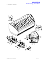
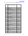
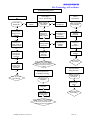
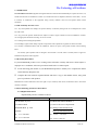
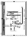
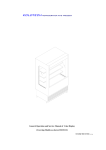
KOLDTECH REFRIGERATOR AND FREEZER General Operation and Service Manual of Ice Cream Showcase OASMs-051-D-06/20/12/06 KOLDTECH The Technology of Excellence CONTENTS Topics Description Page Topics Description Page 5 TEMPERATURE SETTING 6 7 LAST 1 INTRODUCTION 3 2 INSTALLATION & STARTS UP 3 3 2.1 Uncrating 3 6 5.1 Temperature Settings, 5.2 Controller and Parameter ASSEMBLY DRAWING 2.2 Handling Issue 3 7 RECOMMENDED PARTS 10 2.3 Installation 3 8 11-14 2.4 Draining 4 9 TROUBLE SHOOTING TABLES AND TREES WARRANTY & SERVICE 2.5 Ventilation 4 10 2.6 Electrical Preparation 4 11 2.7 Starting 4 12 2.8 Product Loading 4 2.9 Machine Performance 9 15 REFRIGERATION DIAGRAM TIMIMG DIAGRAM 16 LAST 13 I/O UTILITY LOCATION(IF APPLICABLE) ELECTRICAL DIAGRAM 4 14 TEST CERTIFICATE LAST 2.10 Defrosting 4 15 CLAIM FORM LAST PRODUCT CLEANING/Tips 4/ 16 SERVICE RECORD FORM LAST Technical depth as italicized page may be limited to dealer use only. Noted 18 LAST LAST 4 MAINTENANCE SCHDULE OASMs-051-D-20-12-06/8/1/07 5 2 OF 18 KOLDTECH The Technology of Excellence 1. INTRODUCTION: Thank you for choosing our KOLDTECH product. With over 30 years of experience in refrigeration manufacturing we are confident that our product will provide you with years of trouble-free operation. Our products are fully engineered to be amongst the best in the industry. We also continually improve our product designs to ensure they continue to take advantage of the latest in refrigeration design. Every unit is fully tested in our calibrated testing laboratory prior to leaving our factory. As with other precision equipment, proper care and operation will ensure years of trouble-free service. It is essential that you spend time reading this manual before operating the machine, to familiarize yourself with our product and safety procedures. Keep the manual where end-user could see and locate. We thank you again for choosing KOLDTECH . If you have any further questions please feel free to call the dealer from whom you purchased the unit. Our address and telephone number can be found under the “Service and Repair” information section. 2. INSTALLATION AND START UP The following procedure should be followed for trouble free installation: 2.1 Uncrating: While unpacking, take note of any damage to the unit. If damage is found do not discard the packing materials and notify your dealer, or the freight company a.s.a.p. Do not proceed to install the unit. 2.2 Handling Issue: 2.2.1Precaution has been taken to ship the unit in an upright position. If the unit is tilted during transit lubricating oil may shift from the reservoir, and operating the unit may cause excessive wear or damage to the compressor’s moving parts. It is recommended that the unit be left standing for 48 hours before operation. 2.2.2Inspect and clear away any packing material that may be used to secure the unit during transit. 2.3 Installation: 2.3.1 Install the unit in a dry, well-ventilated place away from heat sources or any vibration. Ideally for optimum performance we recommend installation in air-conditioned premises. In the OASMs-051-D-20-12-06/8/1/07 3 OF 18 KOLDTECH The Technology of Excellence event of high relative humidity, condensation may form on the cabinet. This will not impact on the ability of the cabinet to maintain internal temperature. Should ambient temperature exceed 36oC we cannot guarantee the maintenance of internal temperature to required standards. 2.3.2 The unit should be set on a level and firm surface. 2.4 Draining: Special models may require drain pipe for condensate water, End-user should well explore from specification sheet before plugging in and self prepare of drain pipe as appropriate. 2.5 Ventilation: ventilating grills or louvers must not be obstructed for proper operation. 2.6 Electrical Work Preparation: 2.6.1 For safety reasons, the unit must be properly earthed. Check and make sure that the outlet is properly grounded. If a grounded plug is not available, a separate earth ground must be installed to prevent any electrical hazard. A properly rated circuit breaker should be installed to the supply outlet. Check for proper supply voltage before plugging in the unit. Please refer to voltage requirements on the nameplate of the unit. 2.6.2 Plug the unit into the wall outlet. Turn the unit on using the on/off switch. 2.7 Starting: After turning on the unit for the first time, if there is any unusual odour, heat, smoke or vibration immediately turn off and unplug the unit and call for a service technician. The unit should be closely monitored during the first hour of operation. 2.8 Product Loading: The thermostat is set at the factory for optimum operating temperature. Time taken to attain the operating temperature depends on the temperature of the food being loaded, the frequency of the door opening, ambient temperature etc. The unit should reach operating temperature during the first 4-6 hours for chiller and 8-12 hours for freezer of operation 2.9 Machine Performance: To prevent compressor damage, the unit is equipped with a Time Delay Circuit, which shall activate the compressor within 2 minutes after turning on the power or after restarting. 2.10 Defrosting: Defrosting the circuit is set from the factory for optimum operation. Do not attempt to alter the setting. PLS NOTE do not disassemble the unit. Any service performed by parties other than our authorized may void the warranty. 3. PRODUCT CLEANING 3.1 CLEANING Stainless Steel surface, P.V.C. and Display Glass: Users can wash by lukewarm soapy water (or recommended cleaner)and, later, thoroughly rinses or wiping all surfaces with water or moistened clothes respectively. Finally, polish with dry soft cloth. OASMs-051-D-20-12-06/8/1/07 4 OF 18 KOLDTECH The Technology of Excellence 3.2 Note: Do not use solvents or other aggressive liquids for cleaning e.g. with mixture of chlorine or detergent etc. Do not use wire brush, steel wool or grainy –wiping pad such as Scotbrite-pad-grain. 4. MAINTENANCE 4.1 Observe safety practice by disconnecting all electrical supply before performing any kind of maintenance. 4.2 Do not use sharp instruments or cleaning agents on the unit. Clean (interior and exterior surfaces) using a damp cloth and warm water. Food particles and spillage should be removed as soon as possible to avoid build-up and odour. 4.3 To ensure efficiency and reliability it is important that the condenser coil be kept clear of accumulated dirt and duct. It is recommended to use a non-metallic brush, vacuum cleaner or air blower to dislodge dust from the condenser fins. The frequency of cleaning depends on the amount of dust in the surrounding area of the installation. The condenser should be inspected and cleaned at least every month. 4.4 Do not expose any electrical components to moisture or water. If the unit gets wet, turn it off and unplug it from the wall outlet immediately. Do not turn it on again until the unit is completely dry or after inspection by a qualified service technician. 4.5 Should the unit be left unused for an extended period, all food items should be removed. The interior surface and shelves should be cleaned thoroughly. Unplug the unit from the power source and leave the doors slightly opened. Recommended Maintenance Schedule Maintenance List Clean interior and exterior surfaces Check operating temperature Check control panel alarm Check compressor for vibration Check compressor temperature Check condenser fan Clean condenser coil OASMs-051-D-20-12-06/8/1/07 Daily X X X Frequency Weekly Monthly X X X X 5 OF 18 KOLDTECH The Technology of Excellence 5. TEMPERATURE SETTING: 5.1 Your KOLDTECH product is equipped with an electronic thermostat with off cycle designed for refrigeration applications at normal temperature. It provides a relay output to drive the compressor and a probe input. An internal timer manages the off cycle defrost. Tips: Recommended preset temperatures for specialized use. Flowers: +4°C to +8° C Confectionery (Candy): +14°C to +18°C Seafood: -1°C to +1°C Meat: -2°C to +1°C Cakes: +7°C to +10°C (Consult factory when needed, self-adjustment may void the given warranty) 5.2 Front Panel Commands To display and modify target set point; in programming mode it selects a parameter or confirm an operation. By holding it pressed for 3s when max or min temperature is displayed it will be erased. : To see the max. stored temperature; in programming mode it browses the parameter codes or increases the displayed value. By holding it pressed for 3s the fast freezing cycle is started. To see the min stored temperature; in programming mode it browses the parameter codes or decreases the displayed value. By holding it pressed for 3s the defrost is started. Switch ON and OFF the cold room light. Switch ON and OFF the instrument. Key combinations: + To lock and unlock the keyboard. + To enter the programming mode. + To exit the programming mode. OASMs-051-D-20-12-06/8/1/07 6 OF 18 KOLDTECH The Technology of Excellence Use of LEDs A series of light points on the front panels is used to monitor the loads controlled by the instrument. Each LED function is described in the following table. LED MODE Function ON FLASHING The compressor is running - Programming Phase (flashing with LED ) - Anti-short cycle delay enabled The fan is running Programming Phase (flashing with LED ) The defrost is enabled Drip time in progress The Fast Freezing cycle is enabled - ALARM signal - In “Pr2” indicates that the parameter is also present in “Pr1” ON FLASHING ON FLASHING ON ON Function of the LEDs placed on the left top side of buttons: BUTTON SET SET DEFROST LIGHT ON/OFF MODE FLASHING FAST FLASHING ON ON ON OASMs-051-D-20-12-06/8/1/07 FUNCTION The Set point is displayed and it can be modified The Energy Saving is enabled The Manual Defrost is activated The Light is ON The instrument is OFF 7 OF 18 KOLDTECH The Technology of Excellence ALARM SIGNALS Message Cause Outputs “P1” Thermostat probe failure Alarm output ON; Compressor output according to parameters “COn” and “COF” “P2” Evaporator probe failure Alarm output ON; Other outputs unchanged “P3” Auxiliary probe failure Alarm output ON; Other outputs unchanged “HA” Maximum temperature Alarm output ON; Other outputs unchanged alarm “LA” Minimum temperature Alarm output ON; Other outputs unchanged alarm “EE” Data or memory failure Alarm output ON; Other outputs unchanged “dA” Door switch alarm Alarm output ON; Other outputs unchanged “EAL” External alarm Alarm output ON; Other outputs unchanged “BAL” Serious external alarm Alarm output ON; Other outputs OFF “PAL” Pressure switch alarm Alarm output ON; Other outputs OFF The alarm message is displayed until the alarm condition is recovery. All the alarm messages are showed alternating with the room temperature except for the “P1” which is flashing. To reset the “EE” alarm and restart the normal functioning press any key, the “rSt” message is displayed for about 3s. OASMs-051-D-20-12-06/8/1/07 8 OF 18 KOLDTECH The Technology of Excellence 6. ASSEMBLY DRAWING CONTROL PANEL Condensing Unit Condensing Unit OASMs-051-D-20-12-06/8/1/07 9 OF 18 KOLDTECH The Technology of Excellence 7. RECOMMENDED SPARE PARTS OF KOLDTECH PRODUCT DESCRIPTION VOLTAGE ITEM FREQUENCY 1 2 3 4 5 6 7 8 9 10 11 12 13 14 15 16 17 18 19 20 21 22 23 24 refers : standard equipped spec. 220 Volt 50 Cycle (others.) Volt 60 Cycle COMPRESSOR CONDENSER COIL CONDENSER FAN MOTOR CONDENSER FAN BLADE /FAN GRILL RECEIVER TANK LIQUID FILTER DRIER SIGHT GLASS SOLENOIL VALVE PRESSURE REGURATOR EVAPORATOR COIL1 EVAPORATOR COIL2 EVAPORATOR FAN MOTOR EXPANSION VALVE/ORIFIC DIGITAL CONTROL LAMP LAMP SOCKET LAMP DIFFUSER LAMP DIFFUSER CAP BALAST STARTER ELECTRONIC CONTACTOR THERMOSTAT DRAIN HOT GAS CAKE DISPLAY HEATER DRAIN OASMs-051-D-20-12-06/8/1/07 1112464 25423511 1012916 100105/179294 I136021 134030 14203 132033 13312 2637112 2647110 102582 13102/1301 0874512 09858 098974 0743815 0741251 097165 09709 0962204 139120 999DCD 12021500 10 OF 18 KOLDTECH The Technology of Excellence 8. TROUBLE SHOOTING TABLE AND TROUBLE SHOOTING TREES Symptoms Possible Cause Compressor is 1. Main switch is disconnected not run 2. Fuses are blown. 1. 2. 3. Thermal overload is tripped. 3. 4. Magnetic contactor /coil is out of order 4. 5. System shut down by safety devices. 5. 6. Liquid line (or solenoid valve) is not open. 7. Compressor Motor drive. 8. Loosened wiring. 9. (of 3 Phase system), Phase may be lost. Compressor is 1. Liquid refrigerant returns into unusually crankcase. sounded or 2. Refrigerant Pipe is not well erected vibrated 3. Compressor mechanism loosened. 4. Internal balance springs or Neoprene choke are broken High 1. Condensation fail discharge 2. System is overcharged refrigerant. pressure 3. Fan is off 4. Condenser fins are dusty Low 1. Compressor valve is damage discharge 2. Insufficient refrigerant in system. OASMs-051-D-20-12-06/8/1/07 6. Actions Close switch properly. Check electrical circuit and motor winding for shorted or grounded. Investigate for possible overloading. Replace fuse after fault is re-corrected. Overload is automatically reset. Check unit closely when unit resumes normal. Repair or replace. Determine type and cause of shutdown and correct it before resetting safety switch. Check TXV, (Repair or replace coil.) 7. Check motor if opens windings, short turn or burnt and disconnected. 8. Check all wires termination. Tighten all the loosened screws. 9. Test all conductors continuity. 1. Check setting of expansion valves. 2. Provide proper fastener 3. Repair. 4. Replace. 1. 2. 3. 4. 1. 2. Rectify cause of fails Remove the excessive Check electrical circuit. Clean. Check compression ratio or open it. Check leaking and recharge refrigerant 11 OF 18 KOLDTECH The Technology of Excellence pressure High suction pressure Low suction pressure Compressor loses oil 3. 1. 2. 1. 2. 3. 4. 5. 1. 2. 3. 4. Compressor 1. thermal 2. protector switch 3. is open. Stop valve is yet closed. Excessive chilled product. Expansion valve overfeeding. Lack of refrigerant. Evaporator is full of ice Clogged liquid line. Expansion valve malfunctioning. Improper TXV. Leaking of refrigerant. Loosened cylinder ring Refrigerant flood back. 3. Open stop valve properly. 1. Chilled volume to specification 2. Check remote bulb. Regulate superheat. 1. Check leaking and fix. 2. Defrost system does not work. 3. Replace Stainer-Drier 4. Check and reset for proper superheat. 5. Check for proper sizing. 1. Check leaking and recharge refrigerant. 2. Replace compressor. 3. Maintain proper superheat at compressor. Pipe sizing or trapping is not correct 4. Re-correct piping. Operating beyond design conditions. 1. Tuning facilities to the allowable limits. Condenser fins are overly dirty 2. Clean Fin coil. Overcharged refrigerant 3. Release the excessive Evaporator Trouble shooting Symptoms Possible Causes Fan(s) is not turned. 1. Main switch is open. 2. Fuses are blown. 3. Motor is out of order. 4. Defective Timer or defrost thermostat. 5. Unit is in defrosts cycle. 6. Coil is not cooled down enough to reset thermostat. Room temperature is too 1. Room temp. is overly set. high. 2. Superheat is too high. 3. Refrigerant is shortage. 4. Evap. Coil is highly ice accumulation. OASMs-051-D-20-12-06/8/1/07 1. 2. 3. 4. Actions Close switch. Replace fuses. Check cause of short circuits or overload conditions. Replace motor. Replace defective component. 5. Wait until resuming 6. Adjust fan delay setting or wait until resuming. 1. Properly tune thermostat. 2. Adjust thermal expansion valve. 3. Check, fix leaking, and Recharge ref. 4. Do Manually defrost and check defrost control setting 12 OF 18 KOLDTECH The Technology of Excellence Ice is accumulating on 1. Defrost duration is too long. ceiling around 2. Fan delay does not activate evaporator and/or on fan fans after defrost period. guards venturi or blades. 3. Defrost thermostat or timer is out of order 4. Frequently Defrosting action Evap.Coil is not cleared 1. During defrosting, Temp of of frost during defrost Evap. coil is lower than cycle. freezing temp. 2. Cycle of defrost is not enough 3. Defrost cycle too short. 4. Defective Timer or defrost thermostat. Ice accumulating in 1. Condensate (pan) heater is drain pan out of order. 2. Drainpipe is clogged of ice. 3. Drain heater is out of order. 4. Timer/thermostat is out of order OASMs-051-D-20-12-06/8/1/07 1. Adjust defrost termination value 2. Thermostat is not defrost, or adjusted properly. 3. Replace defective component. 4. Reduce number of defrost cycle set. 1. Check heater if operation is normal. 2. Adjust Timer for more defrost cycles. 3. Adjust defrost thermostat or Timer for longer cycle. 4. Replace defect component. 1. Replace heater. 2. Clear drain line. 3. Replace heater, remove clogging 4. Replace defective component. 13 OF 18 KOLDTECH The Technology of Excellence Troubleshooting Trees Machine Does Not Run is the main switch off? Overly High or Overly Low Pressure No Turn on the switch Yes check the correct power supply to the machine Yes check continuity of supply cords & protection fuse Yes check cap.start, (and cap.run) and magnetic contactors Does machine meet sufficient refrigerant? No Isolator Trips Oftenly recharge the refrigerant Yes check suction pipes that no sqeezed, or blazing clogged Yes yes repair the squeezed point or bottle necked point check overly charging refrigerant no no check TXV for moisture-based restriction check overload is set sufficiently Yes No check refrigerant leakage and amperage consumption replace drier, evacuate and recharge system check compressor wdg.if shorted-turn no check earth leaking no No Yes check control board wiring continuity and termination Yes action as per root cause finding Hi side pressure, Lo side pressure and Current consumption shall be related to each others, record data during commissioning shall be available System Operates but no Chilling or Freezing check type of refrigerant Yes check leakage of refrigerant action as per root cause finding Abnormal Sound during Operation check securing and all movable mechanism Yes check bearings, bush and fan blades Yes no check temp. controller setting & functioning action as per root cause finding Yes Hi side pressure, Lo side pressure and Current consumption shall be related to each others, record data during commissioning shall be available OASMs-051-D-20-12-06/8/1/07 14 OF 18 KOLDTECH The Technology of Excellence 9. WARRANTY 9.1 KOLDTECH warrants equipment sold against defects in material and workmanship for a period of twelve (12) months from the date of installation or fifteen (15) months from date of shipment (whichever comes first). Access to warranty is conditional on the equipment being correctly installed, cared for and operated under normal conditions 9.2 The warranty does not cover: 9.2.1 Any consequential loss, damages or expenses directly or indirectly arising from use or attempted use or from any other cause. 9.2.2 Any part of the product which has been subject to misuse, neglect, alteration, incorrect installation, accident, use of inappropriate chemicals, flooding, fire or acts of God. 9.2.3 Damage caused during transportation. 9.2.4 Breakage of glass, bulbs, lamps or plastic components or the replacement of gaskets or fluorescent tubes. 9.2.5 Penalty or additional labour costs for installation, removal or repair of the product outside normal working hours. All warranty parts requested will be charged to the customer’s account unless a warranty claim is approved. Standard credit policies will be applied. 9.3 Warranty Procedures If your KOLDTECH product is not working while still under warranty and has not been subject to improper use or treatment, follow the procedure listed below to obtain repairs: Locate the rating plate sticker on your KOLDTECH product to enable you to complete the details on the Warranty Request Form. Complete the form with all requested details and faxes a copy to the number shown, along with proof of purchase of the product. Manufacturer and the authorized reserve the right to reject warranty calls where circumstances fail to meet their warranty conditions. 9.4 Parts Ordering and Service Procedures 9.4.1 Replacement Parts Replacement parts are available as shown: In Australia: In Asia, South East Asia and others: Tom Stoddart Pty Ltd 215 Jackson Road Sunnybank Hills Q 4109 Australia Ph: 61 7 3345 5011 Fax: 61 7 3344 6166 To contact the nearest dealers or by e-mail to the service department. Att: [email protected] [email protected] Ph: 66 02 316 0770 Fax: 66 037 294 181 OASMs-051-D-20-12-06/8/1/07 15 OF 18 KOLDTECH The Technology of Excellence 9.4.2 Damages and Shortages If the KOLDTECH product is damaged during transport please contact your dealer a.s.a.p. 9.4.3 Service To arrange service on your KOLDTECH product please contact the dealers’ service department In Australia In Asia, South East Asia and others: Tom Stoddart Pty Ltd 215 Jackson Road Sunnybank Hills Q 4109 Australia Ph: 61 7 3345 5011 Fax: 61 7 3344 6166 To contact the nearest dealers or by e-mail to the service department. Att: [email protected] [email protected] Ph: 66 02 316 0770 Fax: 66 037 294 181 10. Topic 11 12 13 14 15 16 FUNDAMENTAL REFRIGERATION DIAGRAM Descriptions ELECTRICAL SCHEMATIC DIAGRAM UTILITY INLETS/OUTLETS LAYOUT OF THIS UNIT IS N/A COMBINATIVE TIMING DIAGRAM COPY OF TEST CERTIFICATE BLANK-CLAIM FORM BLANK-SERVICE RECORD FORM OASMs-051-D-20-12-06/8/1/07 Locations Last attaching, respectively. 16 OF 18 KOLDTECH The Technology of Excellence CAUTION 1 : NOT TO Overloading the outlet by multisockets CAUTION 2 : NOT TO Repairing or remove without know - how (one outlet one appliance) 3. : NOT TO Spraying the unit with water 4 : NOT TO Cleaning plug - pins by soaked cloth 5 : NOT TO Holding the cord when unplugging 6 : NOT TO Tempering the electric cord (Hold plug head is suggested ) 7 : NOT TO Having back of the unit press against cord 9 : NOT TO Having stuff place on top of the unit 11 : NOT TO Using wet hands whilst pluging and 8 : NOT TO Having electrical cord trapped under the unit or other machine 10 : NOT TO Neglecting securing earthing 12 : NOT TO Playing ( Hanging ) on door leave unplugging 13 : NOT TO Storing flammable or explosive material, liquid, or gas inside the unit 15 : NOT TO Using flammable spray near the unit 14 : NOT TO Storing extremely temperature sensitive stuffs eg medical, relevant researching materials 16 : NOT TO start up the unit when having gas leakging near by, open windows (door ) to firstly dilute gas density is a must 17 : NOT TO Using the damaged electrical cord 18 : NOT TO Installing the unit exposedly to water or high moisture 19 : NOT TO Placing glass bottle items in freezer 20 : NOT TO Subjectively playing ( Setting ) temperature( R : 3 C - 13 C, F : -20 C - 0 C ) 21 : NOT TO Attempting to remove the unit with unproper method 22 : NOT TO Touching frozen foods or frozen metal container with bare hands, it can cause cold burn 23 : NOT TO Placing movers hands under the unit when handling, to use dolly as necessary 24 : NOT TO Unplugging the unit whenever intermediate service needed when handling 25 : NOT TO Replugging so soon, but wait for 26 : NOT TO Forgetting all of the mentioned advice 3 - 6 minutes allowing the system pressure balance then restart achievement C:\Program Fires\My doc~\Suradeje\(CR)\Safety Notices\Safety Notices OASMs-051-D-20-12-06/8/1/07 REV.A : 27/10/03/SE. 17 OF 18 Switch/Pwr Energize Compressor Work Condenser Fan Motor Cut- Off Cycle Defrost (assume hot gas type) Cut- in Cycle Evaporator Fan Motor Resume Next Cycle What if MCB is tripped Manually reset MCB What if Over load is tripped Over load automatic resume 1 2 3 4 5 6 7 8 9 10 11 12 : Operating Within 1 hours at -20 C(Freezer) 'BLANK' : at -18 C(Freezer Unit combination timing diagram Off time Compressor Resume Runing after 1 to 2 minute breake KOLDTECH The Technology of Excellence OASMs-051-D-20-12-06/8/1/07 18 OF 18 Label Name Set Hy LS US OdS AC CCt COn COF REGULATION Set point Differential Minimum set point Maximum set point Outputs activation delay at start up Anti-short cycle delay Compressor ON time during fast freezing Compressor ON time with faulty probe Compressor OFF time with faulty probe CF rES Lod Red Temperature measurement unit Resolution (integer/decimal point) Local display Remote display tdF EdF SdF dtE IdF MdF dFd dAd Fdt dPO dAF FnC Fnd FSt ALC ALU ALL AFH ALd dAO EdA dot dOA nPS Range Default Level °C/°F XW260K LS÷US -5/23 Pr1 0,1÷25,5 °C, 1÷45°F 2/4 Pr2 -50,0°C÷SET ,-58°F÷SET -30/-22 Pr2 SET ÷ 110°C, SET ÷ 230°F 20/68 Pr2 0÷255 min. 1 Pr2 0÷30 min. 1 Pr1 0 ÷ 23h 50 min. 0 Pr2 0÷255 min. 15 Pr2 0÷255 min. 30 Pr2 DISPLAY °C ÷ °F °C Pr2 in ÷ de de Pr1 P1 ÷ 1r2 DEFROST Defrost type rE, rT, in Defrost mode In, Sd Set point for SMART DEFROST -30 ÷ +30°C ,-22÷+86°F Defrost termination temperature (1°Evaporator) -50,0÷110°C ,-58÷230°F Interval between defrost cycles 1÷120h (Maximum) length for 1° defrost 0÷255 min. Displaying during defrost rt, it, SEt, dEF, dEG MAX display delay after defrost 0÷255 min. Draining time 0÷60 min. First defrost after start up n÷y Defrost delay after fast freezing 0 ÷ 23h 50 min. FANS Fans operating mode C-n, C-y,O-n, O-y Fans delay after defrost 0÷255 min. Fans stop temperature -50,0÷110°C, -58÷230°F ALARMS Alarmms configuration : relative/absolute rE÷Ab MAXIMUM temperature alarm -50,0÷110°C ,-58÷230°F minimum temperature alarm -50,0÷110°C ,-58÷230°F Temperature alarm and fan differential 0,1÷25,5 °C , 1÷45°F Temperature alarm delay 0÷255 min. Delay of temperature alarm at start up 0 ÷ 23h 50 min. Alarm delay at the end of defrost 0÷255 min. Delay of temperature alarm after closing the door 0÷255 min. Open door alarm delay 0÷254 min.,nu Pressure switch activation number 0÷15 Setting XW260K -25 2.0 -30.0 -5.0 1 2 00:00 20 5 P1 Pr2 °C dE P1 P1 rE In 0/32 8/46 6 30 It 30 0 N 2 Pr1 Pr2 Pr2 Pr1 Pr1 Pr1 Pr2 Pr2 Pr2 Pr2 Pr2 in In 0 20.0 4 20 dEF 15 0 n 00:00 O-n 10 2/35 Pr2 Pr2 Pr2 O-n 3 20.0 rE 10/20 10/20 2/4 15 1,3 30 15 15 0 Pr2 Pr1 Pr1 Ab -10.0 -35.0 2.0 30 08:00 60 15 3 1 Pr2 Pr2 Pr2 Pr2 Pr2 Pr2 Label APb CAO Ot OE O3 P2P P3P HES Odc I1P I2P i2F dId Adr rEL Ptb Prd Pr2 Name Range ANALOGUE OUTPUT 4÷20mA (Optional) Analogue output band width -50,0÷110°C ,-58÷230°F Input type for the analogue output P1÷1r2 ANALOGUE INPUTS Thermostat probe calibration -12,0÷12,0°C , -21÷21°F Evaporator probe calibration -12,0÷12,0°C ,-21÷21°F Auxiliary probe calibration -12,0÷12,0°C , -21÷21°F Evaporator probe presence n÷y Auxiliary probe presence n÷y Temperature increase during the Energy Saving cycle -30÷30°C , -22÷86°F DIGITAL INPUTS Open door control No, Fan, ,CPr, F_C Door switch polarity CL÷OP Configurable digital input polarity CL÷OP Digital input configuration EAL, bAL, PAL, dFr, AUS, ES, OnF Digital input alarm delay 0÷255 min. OTHER Serial address 0÷247 Software release --Map code --Probes display Pb1÷Pb3 Access parameter list --- Default Level Setting 0 P1 Pr2 Pr2 - 0 0 0 y n 0 Pr1 Pr2 Pr2 Pr2 Pr2 Pr2 0.0 0.0 0.0 y n 0 Fan CL CL EAL Pr2 Pr2 Pr2 Pr2 no CL CL EAL 5 Pr2 3 1 1.0 ------- Pr1 Pr2 Pr2 Pr2 Pr2 1 5 Pb2