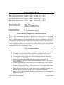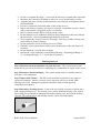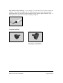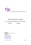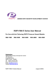
1
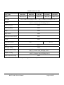
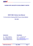
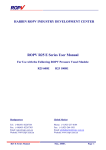
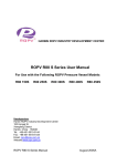
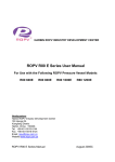
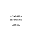
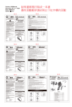
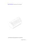
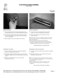
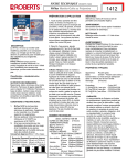
HARBIN ROPV INDUSTRY DEVELOPMENT CENTER
ROPV R40 S Series User Manual
For Use with the Following ROPV Pressure Vessel Models:
R40 150S
R40 250S
R40 300S
R40 400S
R40 450S
Headquarters
Harbin ROPV Industry Development Center
100 Hongqi St.
Xiangfang District
Harbin, China 150036
Tel: +86-451-5515-5144
Fax: +86-451-5515-5124
Email: [email protected]
Website:www.ropv.com.cn
ROPV R40 S Series Manual
August 2005G
General Product Description – R40 S Series
Side Port Membrane Housing
R40 150S Design Pressure: 150PSI / 1.0Mpa / 10Bar (at 120°F / 49°C)
R40 250S Design Pressure: 250PSI / 1.7Mpa / 17Bar (at 120°F / 49°C)
R40 300S Design Pressure: 300PSI / 2.1Mpa / 21Bar (at 120°F / 49°C)
R40 400S Design Pressure: 400PSI / 2.8Mpa / 28Bar (at 120°F / 49°C)
R40 450S Design Pressure: 450PSI / 3.1Mpa / 31Bar (at 120°F / 49°C)
Min. Operating Temp.:
Max. Operating Temp.:
Factory Test Pressure:
Burst Pressure:
Operating pH Range:
Cleaning pH Range:
20°F / -6°C
120°F / 49°C
ASME: 1.1x Design Pressure
Standard: 1.5x Design Pressure
6X Design Pressure
3 – 11
2 – 12 (less than 30 minutes)
General Warning – High Pressure Membrane Housing
ROPV vessels are designed to provide safe operation over a long service life if properly
installed, operated, and maintained. The vessel may cause loss of life, severe bodily
harm, or property damage if not correctly installed, operated, or maintained. Read and
understand all guidelines provided in the vessel User Guide. Observe every precaution
contained therein. Failure to do so may result in malfunction and potential catastrophic
failure. Qualified technicians experienced in servicing hydraulic systems should be used
to work with this vessel. Misuse, incorrect assembly, or use of damaged/corroded
components may result in catastrophic failure.
Vessel Use and Precautions
•
•
•
•
•
•
•
•
•
Positive pressure up to the design pressure (PSI) of the specific model being used.
The required vessel/element interface hardware is supplied with the vessel.
Ensure that an element adapter is installed at each end of the vessel before use.
Vessel expands under pressure and careful consideration must be taken when
installing straps/saddles and system connection piping.
Installation with the straps/saddles provided is strongly recommended.
Vessel should not support any other system components. Connections should be
non-load bearing.
Periodic inspection of the vessel end closure is recommended to ensure all parts
are dry and free of corrosion.
Failure to understand and follow all precautions may void warranty and result in
catastrophic failure of the vessel.
These guidelines are subject to change. Please check with ROPV to ensure that
the User Manual is the latest version for the vessel model being used.
Mount vessel using strap/saddle hardware provided and span recommended in the
engineering drawing.
ROPV R40 S Series Manual
August 2005G
•
•
•
•
•
•
•
•
•
•
•
•
Do not over tighten the straps – vessel must be allowed to expand under operation.
Maximize the connection flexibility to allow for vessel growth under pressure.
Align the end ports with the system manifold, correcting any misalignment before
final installation.
Provide overpressure protection in the system safety devices.
Inspect end closures regularly for signs of corrosion. Immediate corrective action
and/or replacement is suggested in case of corrosion.
Relieve system pressure before working on the vessel.
Do not attempt to over-tighten the Permeate Port connections as this may damage
the end closure. One turn past hand tight should be sufficient.
Never operate the vessel in excess of its ratings. This may void the warranty and
cause bodily or property damage.
Do not operate the vessel permeate port over 125PSI.
Flush the vessel with permeate before system shutdown to reduce the chance of
corrosion.
Do not install the vessel in direct sunlight.
Operate the vessel within the recommended pH range - Operating pH Range: 3 –
11, Cleaning pH Range: 2 – 12 (less than 30 minutes).
End Plug Removal
Step 1 Shut Down System and Relieve System Pressure – The system must be shut
down and all pressure relieved before conducting any maintenance or repair on the vessel.
Step 2 Disconnect Permeate Piping – The system piping must be carefully removed
from the vessel connections.
Step 3 Inspect End Closure – The end closure should be inspected for any signs of
corrosion or damage. Surface corrosion can be removed with a wire brush, while
flushing with water. Damaged components should be replaced with approved
components from ROPV.
Step 4 Disconnect Locking Screws – Each of the two locking crescents is held in place
with a single locking screw. The locking screws can be unthreaded using a hex wrench.
The locking screws should be unthreaded from the end plug only, not from the locking
crescent. The locking screw and locking crescent can be removed together.
ROPV R40 S Series Manual
August 2005G
Step 5 Remove the End Plug – A male nipple is recommended for use when opening the
end plug. Thread the pipe nipple into the feed/concentrate port of the end plug, gently
motion the nipple in various directions, and then gently pull the nipple from the vessel. A
firm tug may be required to release the end plug o-ring seal.
Complete End Plug
End plug for 400/450PSI
ROPV R40 S Series Manual
August 2005G
End Plug Inspection
Step 1 Remove adapter- Grasp the adapter and slowly pull from the end plug. A slight
rotating motion may ease the removal of the adapter. There is one o-ring on the inside
diameter of the permeate port .
Step 2Inspect O-rings - Remove the end plug o-ring, permeate o-ring and adapter oring using a dull, non-metallic tool. All o-rings should be carefully inspected for signs of
damage. It is recommended that all o-rings be replaced during each complete servicing
of the vessel. Failure to do so may cause poor system performance.
Step 3 Inspect End Plug - All end plug components should be free from scratches,
foreign matter, or any sign of damage. Scratched or damaged components should be
replaced with ROPV supplied replacement components. All components should be
cleaned with a mild soap solution or clean water. The components should be air dried or
dried with a lint-free towel.
End Plug Installation
Step 1 General Inspection - Inspect inside of vessel, checking for surface imperfections
or any outside material. Surface imperfections can be removed by lightly sanding the
area with 600-grit sandpaper. Rinse the vessel completely after any repairs.
Step 2 Install Permeate Port and Adapter O-rings – All o-rings should be coated with
a thin layer of glycerine before installation. Seat one permeate port o-ring into each of
the two grooves located at the element end, outside diameter of the adapter.
Location of
Permeate
Port Seal
Step 3 Install Adapter-The adapter should be pushed into the permeate port until the
wider diameter middle section is flush against the end of the permeate port.
Simultaneously pushing and turning the adapter will ease installation.
Step 4 Install End Plug O-ring -Install the end plug seal in the grooved area on the
outside diameter of the end plug - the groove should be clear of any sharp edges and
foreign matter. Take care to ensure that the seals are properly seated in the groove and
are not pinched. Do not use sharp implements when installing the seals.
Step 3 Install the End Plug - Carefully align the end plug at the end of the vessel,
ensuring that the end plug is parallel with the sidewall of the vessel. Slowly insert the
end plug until the retaining groove is visible.
ROPV R40 S Series Manual
August 2005G
Step 4 Install Locking Crescents - Inspect and dry the retaining groove. Place one of
the locking crescents into the retaining groove, while aligning the screw that is prethreaded into the crescent over the threaded hole in the end plug. Ensure that the edge of
the crescent is seated in the retaining groove before you begin threading the screw into
the threaded opening. Once hand tight, the screw can be threaded using a #5 Hex key.
Do not over tighten the screws.
Step 5 Reconnect System Piping
Step 6 Pressurize System – A thorough pre-pressurization inspection should be
conducted, including verifying that the heads are properly installed, system piping
connections are in place, and elements are installed.
Step 7 Inspect for Leaks – All connections should be free from leaks. Do not operate
leaking vessels
ROPV R40 S Series Manual
August 2005G
R40 S Series Parts List
Part Name
R40 150S
R40 250S
R40 300S
R40 400S
R40 450S
Shell
4012.13-18
4012.7-12
4012.1-6
4015.1-6
4015.7-12
End plug
4101(Connect with Adapter 4021) / 4101.1(Connect with Adapter 4021.1)
4021( Connect with End plug 4101) /
4021.1( Connect with End plug 4101.1)
Adapter
Feed/Conc.Port
4004
Retaining Ring
4005
Strap
4008
Strap Screw
4009
Locking Crescent Screw
4012
Saddle
4010
Locking Crescent
Plug
4011
4011.1
4013.1
End plug O-ring
Permeate Port O-ring
Adapter O-ring
Feed/Conc.Port O-ring
4002
4061( Connect with End plug 4101) /
4061.1( Connect with End plug 4101.1)
4007( Connect with End plug 4101 /
4007.1( Connect with End plug 4101.1)
4006
Note: Please see the adapter list to get full series adapter
ROPV R40 S Series Manual
August 2005G
ROPV Limited Warranty
Harbin ROPV Industry Development Center (hereinafter called “ROPV”) vessels (the “Product”) are
warranted to the original purchaser (the “Customer”) under normal use and if installed, operated and
maintained in accordance with applicable User Guides to be free of defects in material and/or workmanship
for a period of one (1) year from date of manufacture subject to the following. Any replacement Product or
Part will be warranted only for the remainder of the original warranty period or thirty (30) days, whichever
is longer.
Exclusions from this Limited Warranty
The warranty shall be void if:
1. defects are not reported during the warranty period.
2. the Product is subject to accident, damage, incorrect installation, mishandling, abuse, misuse, negligence
or accident by any other party.
3. problems caused by modification or alteration.
4. chemical exposure or acts of nature.
5. any item manufactured by other companies.
6. wear on replaceable components under normal conditions – seals are excluded from this warranty.
Procedure for Obtaining Warranty Performance
ROPV reserves the right to determine if a reported defect is a breach of this warranty. This may require, at
ROPV’s discretion, one or more of the following: 1. an inspection or test of the Product and/or the system
in which it was installed by an ROPV representative - the customer is responsible for arranging access to
the Product. 2. an inspection or test of the product and/or the system in which it was installed by the
Customer. 3. an inspection or test of the product and/or the system in which it was installed by third party
inspector appointed by ROPV. 4. return of the Product to ROPV’s factory for inspection or testing. This is
not a statement of limitations for warranty performance and ROPV reserves the right to conduct warranty
performance outside of the items shown.
If the Product is found by ROPV to be defective under the terms of this warranty, ROPV will perform one
of the following at its option: 1. supply a substantially similar replacement part based on FOB factory terms.
2. conduct a field repair of the Product. 3. issue a credit for the original cost of the Products. This is not a
statement of limitations for warranty performance and ROPV reserves the right to conduct warranty
performance outside of the items shown.
Products returned to ROPV for inspection or testing must be shipped freight prepaid at the Customer’s
expense. If a breach of warranty is confirmed, ROPV will bear all costs related to the inspection and
testing. If the Product failure is found to be caused by cause other than breach of warranty, all costs related
to the inspection and testing of the Product will be borne by the Customer. This includes a USD$500 per
day fee and all related travel expenses.
All reported defects must be submitted to ROPV in writing.
Disclaimer
ROPV makes no expressed or implied warranty other than that specifically set forth in this warranty
statement. ROPV disclaims any warranty of merchantability or of fitness for a particular purpose.
ROPV’s liability under the terms of this warranty shall not exceed the purchase price of the Product which
are claimed to be defective. ROPV shall not be liable for any consequential or incidental damages
whatsoever, including but not limited to injuries or damages to person or property, loss of business profits,
business interruption, loss of use, cost of removing/installing Products, or the claims of third parties.
Warranties or Representations by Others
No agent, employee, dealer, or other person has any authority to make any warranties or representations
concerning ROPV or the Product. ROPV is not responsible for such claims of warranty or representation.
ROPV R40 S Series Manual
August 2005G
ROPV R40 S Series Manual
August 2005G
ROPV R40 S Series Manual
August 2005G
ROPV R40 S Series Manual
August 2005G
ROPV R40 S Series Manual
August 2005G
ROPV R40 S Series Manual
August 2005G