1
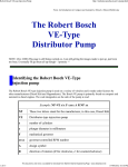
242
244
Service manual
1242
1243
1244
296-12-18 166
Betriebsanleitung engl. 03.99
This Instruction manual is valid for all models and subclasses listed in the
chapter „Specifications“.
The reprinting, copying or translation of PFAFF Instruction Manuals, whether in whole or in
part, is only permitted with our previous permission and with written reference to the
source.
G.M. PFAFF
Aktiengesellschaft
Postfach 3020
D - 67653 Kaiserslautern
Königstr. 154
D - 67655 Kaiserslautern
Editing/Illustrations
Verlag - TD
D - 77901 Lahr
Contents
Contents ............................................................................... Chapter - Page
1
1.01
1.02
1.03
1.04
1.05
1.05.01
1.05.02
1.06
Safety ........................................................................................................................ 1 Directives ................................................................................................................... 1 General notes on safety ............................................................................................. 1 Safety symbols .......................................................................................................... 1 Important notes for the user ...................................................................................... 1 Operating and technical staff ..................................................................................... 1 Operating staff ........................................................................................................... 1 Technical staff ............................................................................................................ 1 Danger warnings ........................................................................................................ 1 -
2
Proper use ................................................................................................................ 2 - 1
3
3.01
3.01.01
3.01.02
3.01.03
3.02
3.02.01
3.02.02
Specifications ........................................................................................................... 3 PFAFF 242 / PFAFF 1242 ........................................................................................... 3 Models and subclasses .............................................................................................. 3 Max. speeds, PFAFF 242 ........................................................................................... 3 Max. speeds, PFAFF 1242 ......................................................................................... 3 PFAFF 244 / PFAFF 1243 / PFAFF 1244 .................................................................... 3 Models and subclasses .............................................................................................. 3 Max. speeds .............................................................................................................. 3 -
4
Machine disposal ..................................................................................................... 4 - 1
5
5.01
5.02
5.03
5.04
Transportation, packing and storage ...................................................................... 5
Transportation to customer’s premises ..................................................................... 5
Transportation inside customer’s premises ............................................................... 5
Disposal of packing materials ..................................................................................... 5
Storage ...................................................................................................................... 5
6
Explanation of symbols ........................................................................................... 6 - 1
7
7.01
7.02
Controls .................................................................................................................... 7 On/off switch ............................................................................................................. 7 Pedal (on machines without automatic backtacking mechanism and
presser foot lifter -911/97 ) ....................................................................................... 7 Pedal (on machines with automatic backtacking mechanism and
presser foot lifter -911/97) ......................................................................................... 7 Pedals (on machines with presser foot lifter) ............................................................. 7 Knee lever (on machines without automatic backtacking mechanism and
presser foot lifter -911/97) ......................................................................................... 7 Key on the machine head (on machines with automatic backtacking mechanism
and presser foot lifter -911/97) ................................................................................... 7 Lever for lifting the presser foot / roller presser ........................................................ 7 Feed regulator and reverse sewing lever ................................................................... 7 Feed regulator (on machines with automatic backtacking mechanism and
presser foot lifter -911/97) ......................................................................................... 7 -
7.03
7.04
7.05
7.06
7.07
7.08
7.09
-
1
1
1
2
2
3
3
3
4
1
1
2
2
2
3
4
4
1
1
1
1
1
1
1
1
2
2
3
3
4
4
5
Contents
Contents ............................................................................... Chapter - Page
8
8.01
8.01.01
8.01.02
8.01.03
8.01.04
8.01.05
8.01.06
8.01.07
8.02
8.03
Installation and initial operation ............................................................................. 8 Installation .................................................................................................................. 8 Adjusting the table-top height .................................................................................... 8 Adjusting the V-belt tension ....................................................................................... 8 Fitting the upper V-belt guard .................................................................................... 8 Fitting the lower V-belt guard ..................................................................................... 8 Fitting the tilt lock ...................................................................................................... 8 Fitting the synchronizer .............................................................................................. 8 Fitting the reel stand .................................................................................................. 8 Commissioning .......................................................................................................... 8 Switching the machine on / off .................................................................................. 8 -
1
1
1
2
2
3
3
4
4
5
5
9
9.01
9.02
9.03
9.04
9.05
9.06
9.07
9.08
Setting up ................................................................................................................. 9 Inserting the needle in the PFAFF 242 and PFAFF 1242 ........................................... 9 Inserting the needle in the PFAFF 1243 ..................................................................... 9 Inserting the needle in the PFAFF 244 and PFAFF 1244 ........................................... 9 Winding the bobbin thread, adjusting the thread tension .......................................... 9 Removing /inserting the bobbin case ......................................................................... 9 Threading the bobbin case / adjusting the thread tension .......................................... 9 Threading the needle thread / adjusting the needle thread tension (PFAFF 1243) ..... 9 Threading the needle thread / adjusting the needle thread tension
(PFAFF 242 and PFAFF .............................................................................................. 9 Threading the needle thread / adjusting the needle thread tension
(PFAFF 244 and PFAFF 1244 ..................................................................................... 9 -
1
1
2
2
3
4
4
5
9.09
6
7
10
10.01
10.02
10.03
10.04
10.05
10.06
10.07
Care and maintenance ........................................................................................... 10
Servicing and maintenance intervals ........................................................................ 10
Cleaning the hook compartment and the hook ........................................................ 10
General lubrication ................................................................................................... 10
Lubricating the hook ................................................................................................ 10
Lubricating the needle head parts ............................................................................ 10
Checking / adjusting the air pressure ....................................................................... 10
Emptying / cleaning the water container of the air filter .......................................... 10
-
1
1
1
2
3
4
4
5
11
11.01
11.02
11.03
Adjustment ............................................................................................................. 11
Notes on adjusting ................................................................................................... 11
Tools, gauges and other accessories ....................................................................... 11
Abbreviations ........................................................................................................... 11
-
1
1
1
1
11.04
11.04.01
11.04.02
11.04.03
11.04.04
11.04.05
11.04.06
Adjusting the basic machine ................................................................................. 11 Positioning the feed dog .......................................................................................... 11 Height of the feed dog ............................................................................................. 11 Pre-adjusting the needle height ............................................................................... 11 Centering the needle in the needle hole (PFAFF 242 and 1242 ............................... 11 Centering the needle in the needle hole (PFAFF 244, 1243 and 1244) .................... 11 Driving motion of the feed dog (PFAFF 242 and 1242) ............................................ 11 -
2
2
3
4
5
6
7
Contents
Contents ............................................................................... Chapter - Page
11.04.07
11.04.08
11.04.09
11.04.10
11.04.11
11.04.13
11.04.14
11.04.15
11.04.16
11.04.17
11.04.18
11.04.19
11.04.20
11.04.21
Driving motion of the feed dog (PFAFF 244, 1243 and 1244) .................................. 11
Lifting motion of the feed dog (PFAFF 242 and 1242) ............................................. 11
Lifting motion of the feed dog (PFAFF 244, 1243 and 1244) ................................... 11
Basic position of the roller presser drive (only on machines with subcl. -4/01) .......... 11
Synchronizing the roller presser and feed dog
(only on machines with subcl. -4/01) ....................................................................... 11
Releasing the roller presser for reverse sewing
(only on machines with subcl. -4/01) ....................................................................... 11
Hook-to-needle clearance, needle rise, needle height and needle guard ................. 11
Bobbin-case opener ................................................................................................. 11
Safety clutch ............................................................................................................ 11
Clearance between presser foot / roller presser and needle plate ........................... 11
Pressure of presser foot / roller presser .................................................................. 11
Needle thread tension release ................................................................................. 11
Thread check spring (PFAFF 1243 and on machines without -900/56) .................... 11
Thread check spring (on two-needle machines with - 900/56) ................................. 11
Bobbin winder .......................................................................................................... 11
11.05
11.05.01
11.05.02
11.05.03
11.05.04
11.05.05
11.05.06
11.05.07
11.05.08
11.05.09
11.05.10
11.05.11
11.05.12
11.05.13
11.05.14
11.05.15
11.05.16
Adjusting the thread trimmer -900/56 .................................................................. 11 - 24
Pre-adjusting the control cam .................................................................................. 11 - 24
Tripping lever ........................................................................................................... 11 - 25
Pawl ......................................................................................................................... 11 - 26
Engaging solenoid .................................................................................................... 11 - 27
Release trip .............................................................................................................. 11 - 28
Engaging lever ......................................................................................................... 11 - 29
Linkage rod .............................................................................................................. 11 - 30
Final adjustment of the control cam ......................................................................... 11 - 31
Catch ........................................................................................................................ 11 - 32
Connecting rod (only for two-needle machines) ...................................................... 11 - 33
Thread-catcher height .............................................................................................. 11 - 34
Knife ......................................................................................................................... 11 - 35
Thread-catcher reverse position ............................................................................... 11 - 36
Bobbin-thread clamp spring ..................................................................................... 11 - 37
Tension release bar .................................................................................................. 11 - 39
Adjusting the synchronizer ....................................................................................... 11 - 41
11.06
11.07
Adjusting the presser bar lifting lever with subclass -911/97 ................................... 11 - 42
Adjusting the presser bar lifting lever without subclass -911/97 .............................. 11 - 43
11.04.12
- 8
- 9
- 10
- 11
- 12
- 13
- 14
- 16
- 17
- 18
- 19
- 20
- 21
- 22
- 23
Safety
1
Safety
1.01
Regulations
This machine is constructed in accordance with the European regulations indicated in the
conformity and manufacturer's declarations.
In addition to this instruction manual, please also observe all generally accepted, statutory
and other legal requirements, including those of the user's country, and the applicable pollution control regulations!
The valid regulations of the regional social insurance society for occupational accidents or
other supervisory authorities are to be strictly adhered to!
1.02
General notes on safety
● The machine must only be operated by adequately trained operators and only when the
instruction manual has been fully read and understood!
● All notices on safety and the instruction manual of the motor manufacturer are to be
read before the machine is put into operation!
● All notes on the machine concerning danger and safety must be observed!
● The machine must be used for the purpose for which it is intended and must not be
operated without its safety devices; all regulations relevant to safety must be adhered
to.
● When part sets are changed (e.g. needle, presser foot, needle plate, feed dog or bobbin), during threading, when the workplace is left unattended and during maintenance
work, the machine must be isolated from the power supply by turning off the on/off
switch or removing the plug from the mains!
● Daily maintenance work must only be carried out by appropriately trained persons!
● Repairs and special maintenance work must only be carried out by qualified technical
staff or persons with appropriate training!
● During maintenance or repairs on the pneumatic system the machine must be isolated
from the compressed air supply! The only exception to this is when adjustments or
function checks are carried out by appropriately trained technical staff!
● Work on the electrical equipment must only be carried out by technical staff who are
qualified to do so!
● Work on parts or equipment connected to the power supply is not permitted! The only
exceptions to this are specified in regulations EN 50110.
● Conversion or modification of the machine must only be carried out under observation of
all relevant safety regulations!
1-1
Safety
● Only spare parts which have been approved by us are to be used for repairs! We draw
special attention to the fact that spare parts and accessories not supplied by us have not
been subjected to testing nor approval by us. Fitting and/or use of any such parts may
cause negative changes to the design characteristics of the machine. We shall not accept any liability for damage caused by the use of non-original parts.
1.03
Safety symbols
Danger!
Special points to observe.
Danger of injury to operating or technical staff!
1.04
Important notes for the user
● This instruction manual belongs to the equipment of the machine and must be available
to the operating staff at all times.
This instruction manual must be read before the machine is operated for the first time.
● Both operating and technical staff must be instructed on the safety devices of the machine and on safe working methods.
● It is the duty of the user to operate the machine in perfect running order only.
● The user must ensure that none of the safety devices are removed nor put out of working order.
● The user must ensure that only authorized persons operate and work on the machine.
For further information please refer to your PFAFF agency.
1-2
Safety
1.05
Notes for operating and technical staff
1.05.01
Operating staff
Operating staff are the persons responsible for setting up, operating and cleaning the machine and for removing any disturbances in the sewing area.
The operating staff are obliged to observe the following points, and must:
● always observe the notes on safety in this instruction manual!
● avoid using any working methods which adversely effect the safety of the machine!
● avoid wearing loose-fitting clothing or jewelry such as necklaces or rings!
● also ensure that only authorized persons are allowed near the danger area of the
machine!
● immediately report to the user any changes to the machine that may affect its safety!
1.05.02
Technical staff
Technical staff are persons who have been trained in electrical engineering, electronics,
pneumatics and mechanical engineering. They are responsible for lubricating, servicing,
repairing and adjusting the machine.
The technical staff are obliged to observe the following points, and must:
● always observe the notes on safety in this instruction manual!
● switch off the on/off switch before carrying out adjustment and repair work and ensure it
cannot be switched on again unintentionally!
● never work on parts or equipment still connected to the power supply! Exceptions to this
are only permissible according to regulations EN 50110;
● isolate the machine from the compressed air supply when carrying out maintenance or
repair work on pneumatic equipment!
Exceptions to this are only permissible for function checks;
● replace all safety covers after carrying out maintenance or repair work!
1-3
Safety
1.06
Danger warnings
A working area of 1 metre is to be kept free both in front of and behind the
machine while it is in operation, so that it is always easily accessible.
Never reach into the sewing area while sewing! Danger of injury by the needle!
Never leave objects on the table while adjusting the machine settings! Objects
can become trapped or be hurled out! Danger of injury!
On mechanically activated clutch motors without an actuating lock, wait until
the motor has come to a standstill! Danger of injury!
3
1
5
0
1
2
3
4
2
Fig. 1 - 01
Do not operate the machine without the take-up lever guard 1!
Danger of injury due to the movement of the take-up lever !
Do not operate machines with a presser foot without the finger guard 2!
Danger of injury by the moving needle!
Do not operate the machine without belt guards 3 and 4!
Danger of injury by the revolving drive belt!
Do not operate the machine without tilt-back safeguard 5!
Danger of fingers being crushed if the machine closes accidentally!
1-4
Proper use
2
Proper use
The PFAFF 242 is a two-needle lockstitch sewing machine with needle feed and vertical
sewing hook.
The PFAFF 1242 is a two-needle lockstitch sewing machine with needle feed and large
vertical sewing hook.
The PFAFF 1243 is a single-needle lockstitch sewing machine with roller presser and large
vertical sewing hook.
The PFAFF 244 is a two-needle lockstitch sewing machine with roller presser and vertical
sewing hook.
The PFAFF 1244 is a two-needle lockstitch sewing machine with roller presser and large
vertical sewing hook.
The machines are used for producing lockstitch seams in the textile and leather industries.
Any use of these machines which is not approved by the manufacturer shall be
considered as improper use! The manufacturer shall not be liable for any
damage arising out of improper use! Proper use shall also be considered to
include compliance with the operation, adjustment, service and repair
measures specified by the manufacturer!
2-1
Specifications
3
Specifications
3.01
PFAFF 242 / PFAFF 1242 ◆
Stitch type: .................................................................................................. 301 (lockstitch)
Needle system: ............................................................................................................. 134
Needle thickness in 1/100 mm:
Model B: ................................................................................................................ 80 - 100
Model C: .............................................................................................................. 110 - 140
Max. thread size (synthetic▲ ):
Model B: ...................................................................................................................... 40/3
Model C: ...................................................................................................................... 15/3
Max. stitch length:
Model BN: ............................................................................................................... 6.0 mm
Model CN: ............................................................................................................... 6.0 mm
Balance wheel eff. dia.:
Model B: .................................................................................................................. 80 mm
Model C: .................................................................................................................. 90 mm
Dimensions of machine:
Length: ...................................................................................................... approx. 530 mm
Width: ....................................................................................................... approx. 177 mm
Height (above table): ................................................................................. approx. 265 mm
Clear workspace width: .......................................................................................... 270mm
Clear workspace height: ........................................................................................ 115 mm
Fabric clearance under roller presser ...................................................................... 8.5 mm
Net weight (machine head) ............................................................................ approx. 42 kg
Power supply: ....................................................................... see motor instruction manual
Max. power consumption: .................................................... see motor instruction manual
Fuse protection: .................................................................... see motor instruction manual
Working air pressure: .................................................................................................. 6 bar
Air consumption: ...................................................................................... ~0.8 l/work cycle
Working noise level:
Emission at workplace
PFAFF 242 at a speed of 2300 spm: ...................................................................... 83 dB(A)
PFAFF 1242 at a speed of 1800 spm: .................................................................... 80 dB(A)
Noise measurement in accordance with DIN 45 635-48-A-1
◆
Subject to technical alterations
▲
Or comparable size of other thread types
3-1
Specifications
3.01.01
Models and subclasses
Model B: ............................................................ For processing medium-weight materials
Model C (only PFAFF 1242): ................................ For processing medium-heavy materials
Additional equipment:
Subclass -900/56 ......................................................................................... Thread trimmer
Subclass -911/97 ...................... Automatic presser-foot lifter with backtacking mechanism
3.01.02
Max. speeds of the PFAFF 242
Model
B
3.01.03
Max.speed (r.p.m.)
up to 10
from 10.4
from 25.2
2900
2700
2400
Max. speeds of the PFAFF 1242
Model
3-2
Needle gauge (mm)
Needle gauge (mm)
Max.speed (r.p.m.)
B
up to 10
from 10.4
from 25.2
2700
2500
2200
C
up to 10
from 10.4
from 25.2
2300
2100
1900
Specifications
3.02
PFAFF 244 / PFAFF 1243 / PFAFF 1244 ◆
Stitch type: .................................................................................................. 301 (lockstitch)
Needle system: ............................................................................................................. 134
Needle thickness in 1/100 mm:
Model A: .................................................................................................................. 60 - 70
Model B: ................................................................................................................ 80 - 100
Model C and C/D: ................................................................................................. 110 - 140
Model D: .............................................................................................................. 160 - 200
Max. thread size (synthetic▲ ):
Model A: ......................................................................................................................
Model B: ......................................................................................................................
Model C and C/D: .........................................................................................................
Model D .......................................................................................................................
60/3
40/3
15/3
11/4
Max. stitch length:
Model AN2.5: .......................................................................................................... 2.5 mm
Model A and B: ....................................................................................................... 4.5 mm
Model CN8; C/DN8 and DN 8: ................................................................................ 8.0 mm
Balance wheel eff. dia.:
Model A and B: ........................................................................................................ 80 mm
Model C; C/D and D: ................................................................................................ 90 mm
Dimensions of machine:
Length: ...................................................................................................... approx. 530 mm
Width: ....................................................................................................... approx. 177 mm
Height (above table): ................................................................................. approx. 265 mm
Clear workspace width: .......................................................................................... 270mm
Clear workspace height: ........................................................................................ 115 mm
Fabric clearance under presser foot ........................................................................... 5 mm
Net weight (machine head) ............................................................................ approx. 42 kg
Power supply: .....................................................................................................................
see motor instruction manual
Max. power consumption: .................................................... see motor instruction manual
Fuse protection: .................................................................... see motor instruction manual
Working air pressure: .................................................................................................. 6 bar
Air consumption: ...................................................................................... ~0.8 l/work cycle
Working noise level:
Emission at workplace
PFAFF 244 at a speed of 2000 spm: ...................................................................... 81 dB(A)
PFAFF 1243 at a speed of 1500 spm: .................................................................... 79 dB(A)
PFAFF 1244 at a spped of 1400 spm: .................................................................... 79 dB(A)
Noise measurement in accordance with DIN 45 635-48-A-1
◆
Subject to technical alterations
▲
Or comparable size of other thread types
3-3
Specifications
3.02.01
Models and subclasses
PFAFF 244
Model A: ............................................................................... For processing light materials
Model B: ............................................................ For processing medium-weight materials
PFAFF 1243 und PFAFF 1244
Model C and C/D: ................................................. For processing medium-heavy materials
Model D: ............................................................................ For processing heavy materials
Additional equipment:
Subclass -750/04 ................................................................................... Roller presser drive
Subclass -900/56 ......................................................................................... Thread trimmer
Subclass -911/97 ....................... Automatic backtacking mechanism and presser-foot lifter
3.02.02
Max. speeds
Machine type
PFAFF 244
PFAFF 1243
PFAFF 1244
3-4
Model
Max.speed (r.p.m.)
A
2500
B
2500
C
2100
C/D
1800
D
1800
C
2000
C/D
1700
D
1700
Disposal of Machine
4
Disposal of Machine
● Proper disposal of the machine is the responsibility of the customer.
● The materials used for the machine are steel, aluminium, brass and various plastic materials.
The electrical equipment comprises plastic materials and copper.
● The machine is to be disposed of according to the locally valid pollution control regulations; if necessary, a specialist is to be commissioned.
Care must be taken that parts soiled with lubricants are dispoed of separately
according to the locally valid pollution control regulations!
4-1
Transportation, packing and storage
5
Transportation, packing and storage
5.01
Transportation to customer's premises
Within the Federal Republic of Germany, complete machines (with table and motor) are
delivered without packing.
Machines without table (only sewing heads) and machines intended for exports are packed.
5.02
Transportation inside the customer's premises
The manufacturer cannot be made liable for transportation inside the customer's premises
nor to other operating locations.
5.03
Disposal of packing materials
The packing materials of this machine comprise paper, cardboard and VCE fibre. Proper disposal of the packing material is the responsibility of the customer.
5.04
Storage
If the machine is not in use, it can be stored as it is for a period of up to six months, but It
should be protected against dust and moisture.
If the machine is stored for longer periods, the individual parts, especially the surfaces of
moving parts, must be protected against corrosion, e.g. by a film of oil.
5-1
Explanation of symbols
6
Explanation of symbols
In this instruction manual, work to be carried out or important information is accentuated by
simbols. These symbols have the following meanings:
Note, information
Cleaning, care
Lubrication
Maintenance, repairs, adjustment, service work
(only to be carried out by technical staff)
6-1
Controls
7
Controls
7.01
On/off switch
● Turn the machine on and off by turning
the on/off switch 1.
The switch in the illustration
can be found on machines with
Quick motors. When other
motors are used, other
switches may be fitted.
1
Fig. 7 - 01
7.02
Pedal
(on machines without automatic backtacking mechanism and presser foot
lifter -911/97)
0
=
Neutral position
+1 =
Sew
-1 =
Trim thread (on machines with
thread trimmer -900/56)
0
+1
-1
Fig. 7 - 02
7-1
For other pedal functions see
the motor instruction manual.
Controls
7.03
Pedal
(on machines with automatic backtacking mechanism and presser foot
lifter -911/97)
0
=
Neutral position
+1 =
Sew
-1 =
Lift presser foot or roller presser
-2 =
Trim thread (on machines with
thread trimmer -900/56)
0
+1
For other pedal functions see
the motor instruction manual.
-1
-2
Fig. 7 - 03
7.04
Pedals (on machines with presser foot lifter -910/01)
0
=
+1 =
Sew
-1 =
Trim thread (on machines with
thread trimmer -900/56)
+2 =
Lift presser foot or roller presser
0
+2
Neutral position
+1
For other pedal functions see
the motor instruction manual.
-1
Fig. 7 - 04
7-2
Controls
7.05
Knee lever (on machines without automatic backtacking mechanism and
presser foot lifter -911/97)
● The presser foot or roller presser is
raised by operating the knee lever 1.
1
Fig. 7 - 05
7.06
Key on the machine head (for machines with automatic backtacking
mechanism and presser foot lifter -911/97)
● Switch to reverse sewing by pressing
key 1 while sewing.
1
Fig. 7 - 06
7-3
Controls
7.07
Lever for lifting the presser foot / roller presser
● The presser foot/roller presser is lifted by
raising lever 1.
Fig. 7-07 shows a PFAFF 1243.
1
Fig. 7 - 07
7.08
Feed regulator and reverse sewing lever
● Adjust the stitch length by turning the
knurled nut on lever 1..
● For reverse sewing push lever 1 up as far
as possible.
When switching over to reverse
sewing, do not sew at maximum
speed.
1
Fig. 7 - 08
7-4
Controls
7.09
Feed regulator
(on machines with automatic backtacking mechanism and presser foot
lifter -911/97)
● The forward stitch length is set by
turning the knurled screw 1.
● The reverse stitch length is set by
turning the knurled screw 2.
2
You can set the length of the
reverse stitch as long as
required, independent of the
foward stitch.
1
Fig. 7 - 09
7-5
The options for setting the
automatic start and end
backtacks are to be found in
the instruction manual of the
motor.
Installation and commissioning
8
Installation and commisioning
The machine must only be installed and comissioned by qualified personnel! All
relevant safety regulations are to be observed!
If the machine is delivered without a table, it must be ensured that the stand
and the table top which you intend to use can hold the weight of the machine.
Adequate stability of the base must be guaranteed - during sewing too.
8.01
Installation
The necessary connections for electricity and compressed air, a level and stable surface and
sufficient lightning must be available at the machine’s location.
Due to reasons of packaging, the table top is lowered during transport.
The following is a description of how to adjust the height of the table top.
8.01.01
Adjusting the table-top height
1
1
2
Fig. 8 - 01
● Loosen screws 1 and 2 and adjust the table top to the required height.
● Tighten screws 1.
● Adjust the pedals to the required setting and tighten screw 2.
8-1
Installation and commissioning
8.01.02
Adjusting the V-belt tension
● Loosen nuts 1.
● Tighten the V-belt with belt take-up
hangar 2.
● Tighten nuts 2.
Fig. 8-02 shows a Quick motor.
If another motor is used,
proceed as described in the
motor’s instruction manual.
2 cm
1
2
Fig. 8 - 02
8.01.03
Mounting the upper V-belt guard
If a large balance wheel is used,
the corner 1 of the belt guard 3
must be broken out.
1
3
2
4
Fig. 8 - 03
8-2
● Screw position stop 2 to the belt guard
section 3.
● Attach belt guard section 3.
● Attach belt guard section 4.
Installation and commissioning
8.01.04
Mounting the lower V-belt guard
● Align belt guard 1 in such a way that both
the motor pulley and the V-belt run
freely.
Fig. 8-04 shows a Quick motor.
If another motor is used,
proceed as described in the
motor’s instruction manual.
1
Fig. 8 - 04
8.01.05
Fitting tilt lock
● Attach tilt lock 1 included in the
accessories with screw 2.
Do not operate the machine
without tilt-over safeguard 1!
Danger of crushing between
upper part and the table top!
2
1
Fig. 8 - 05
8-3
Installation and commissioning
8.01.06
Fitting the synchronizer
● Slide synchronizer 1 onto the shaft.
● Slightly tighten screws 2.
● Insert plug of the synchronizer into the
control box.
● Adjust synchronizer (see Chapter
11.05.16 Adjusting the synchronizer).
2
1
Fig. 8 - 06
8.01.07
Fitting the reel stand
● Fitting the reel stand as shown in
Fig. 8-07.
● Insert reel stand in the table-top hole and
fasten it with the included nuts.
Fig. 8 - 07
8-4
Installation and commissioning
8.02
Initial operation
● Check the machine, in particular the
electrical leads and pneumatic
connection tubes, for any damage.
1
● Remove pin 1 from the oil reservoir 2.
The pin 1 serves only to protect the
machine from damage during
transportation and must not be used
during sewing.
● Clean the machine thoroughly and oil it,
or top up the oil, see Chapter 10 Care
and Maintenance.
2
Fig. 8 - 08
● Have mechanics ensure that the
machine’s motor can be operated with
the available electricity supply and that it
is connected correctly to the terminal
box. If not, the machine must not be
operated.
● The balance wheel must rotate towards the operator when the machine is running. If
not, have the motor connection changed by a mechanic.
● Connect the machine to the compressed air system. The pressure gauge must display a
pressure of approx. 6 bar. If not, adjust the pressure to this value, see Chapter 10.06
Checking / adjusting the air pressure.
8.03
Switching the machine on / off
● Switch the machine on or off, see Chapter 7.01 On/off switch.
● Carry out a test run.
8-5
Setting up
9
Setting up
All regulations and instructions in this instruction manual are to be observed.
Special attention is to be paid to all Notes on Safety!
All setting up work is only to be carried out by appropriately trained personnel.
Before all preparation work, the machine is to be switched off at the on/off
switch or disconnected from the electricity supply by removing the plug from
the mains!
9.01
Inserting the needles in the PFAFF 242 and PFAFF 1242
Turn the machine off!
Danger of injury if the machine
is started accidentally!
Use only system 134 needles.
1
1
● Raise the needle bar as far as possible
and loosen screws 1.
● Insert the needles 2 as far as possible
(the long needle groove of the left
needle must be facing right and that of
the right needle must be facing left).
● Tighten screws 1.
2
2
Fig. 9 - 01
The selection of the needle depends on the machine model and the materials
and threads being used (see Chapter 3 Specifications).
9-1
Setting up
9.02
Inserting the needle in the PFAFF 1243
Turn the machine off!
Danger of injury if the machine
is started accidentally!
Use only system 134 needles.
● Raise the needle bar as far as possible
and loosen screw 1.
● Insert the needle 2 as far as possible (the
long needle groove must be facing left).
● Tighten screw 1.
1
2
Fig. 9 - 02
The selection of the needle depends on the machine model and the materials
and threads being used (see Chapter 3 Specifications).
9.03
Inserting the needles in the PFAFF 244 and PFAFF 1244
Turn the machine off!
Danger of injury if the machine
is started accidentally!
1
Use only system 134 needles.
2
2
● Raise the roller presser and swing it out.
● Raise the needle bar as far as possible
and loosen screw 1.
● Insert the needles 2 as far as possible
(the long needle groove of the left
needle must be facing right and that of
the right needle must be facing left).
● Tighten screws 1.
Fig. 9 - 03
The selection of the needle depends on the machine model and the materials
and threads being used (see Chapter 3 Specifications).
9-2
Setting up
9.04
Winding the bobbin thread, adjusting the thread tension
4
+
-
6
3
1
2
5
Fig. 9 - 04
● Place an empty bobbin 1 onto bobbin spindle 2.
● Thread the bobbin in accordance with Fig. 9-04 and wind it clockwise around the
bobbin 1 a few times.
● Engage on the bobbin winder by pressing bobbin winder shaft 2 and lever 3 at the same
time.
The bobbin fills up during sewing.
● The tension of the thread on bobbin 1 is adjusted with knurled screw 4.
● The bobbin winder stops automatically when there is enough thread on bobbin 1.
If the thread is wound unevenly:
● Loosen nut 5.
● Turn the thread guide 6 accordingly.
● Tighten nut 5.
9-3
Setting up
9.05
Removing /inserting the bobbin case
Turn the machine off!
Danger of injury if the machine
is started accidentally!
1
Removing the bobbin case:
● Raise take-up lever as far as possible.
● Open the cover of the hook
compartment, raise latch 1 and remove
bobbin case 2.
Inserting the bobbin case:
● Insert bobbin case 2 so that it clicks into
place.
● Close the latch 1 and close the cover of
the hook compartment.
2
Fig. 9 - 05
Do not operate the machine when the cover of the hook compartment is open!
Danger of injury by moving parts!
Threading the bobbin case / adjusting the thread tension
Turn the machine off!
Danger of injury if the machine
is started accidentally!
5 cm
9.06
● Thread the bobbin as shown in Fig. 9-06.
● When the thread is pulled, the bobbin
must rotate in the direction of the arrow.
● Adjust the bobbin thread tension with
screw 1.
+
1
Fig. 9 - 06
9-4
Setting up
9.07
Threading the needle thread / adjusting the needle thread tension
(PFAFF 1243)
1
Fig. 9 - 07
Turn the machine off!
Danger of injury if the machine is started accidentally!
● Thread the needle thread as shown in Fig. 9-07. Take care that the needle is threaded
from the left.
● Adjust the needle thread tension by turning the knurled screw 1.
9-5
Setting up
9.08
Threading the needle thread / adjusting the needle thread tension
(PFAFF 242 and PFAFF 1242)
2
1
Fig. 9 - 08
Turn the machine off!
Danger of injury if the machine is started accidentally!
● Thread the needle thread as shown in Fig. 9-08. Take care that the right needle is
threaded from the left and the left needle from the right.
● Adjust the needle thread tension by turning the knurled screw 1 (right needle) or 2 (left
needle).
9-6
Setting up
9.09
Threading the needle thread / adjusting the needle thread tension
(PFAFF 244 and PFAFF 1244)
2
1
Fig. 9 - 09
Turn the machine off!
Danger of injury if the machine is started accidentally!
● Thread the needle thread as shown in Fig. 9-09. Take care that the right needle is
threaded from the left and the left needle from the right.
● Adjust the needle thread tension by turning the knurled screw 1 (right needle) or 2 (left
needle).
9-7
Care and maintenance
10
Care and maintenance
10.01
Servicing and maintenance intervals
Clean the hook compartment .................... daily, several times if in continuous operation
Check the air pressure ............................................................................ daily, before use
Clean the water container of the air filter/regulator ................................ daily, before use
Check the hook oil-container ......................................................................... once a week
Clean the hook .............................................................................................. once a week
General lubrication ....................................................................................... twice a week
Lubricate the needle-head parts .................................................................. twice a week
These maintenance intervals are calculated for the average running time of a
single shift operation. If the machine is operated for a longer period, shorter
intervals are recommended.
10.02
Cleaning the hook compartment and the hook
3
Turn the machine off!
Danger of injury if the machine
is started accidentally!
5 mm
2
Fig. 10 - 01
1
● Clean the hook compartment daily with a
brush, several times if in continuous
operation.
● Clean the hook thoroughly once a week.
● Open the hook compartment cover.
● Raise the needle bar as far as possible.
● Remove the bobbin case cap and the
bobbin.
● Unscrew hook jib 1.
● Turn the balance wheel, until the tip of
the bobbin case 2 penetrates approx. 5
mm into the groove of the hook race.
● In this position remove the bobbin
case 2.
● Clean the hook race with paraffin.
● When inserting the bobbin case, ensure that horn 3 fits into the groove of the needle
plate.
● Screw hook jib 1 back on.
● Insert the bobbin case and close the cover of the hook compartment.
10 - 1
Care and maintenance
10.03
General lubrication
0
1
2
3
Fig. 10 - 02
● Lubricate all bearings above the table top (see arrows) twice a week.
Turn the machine off! Danger of injury!
● Pull the knee lever out to the front and tilt the machine backwards.
● Lubricate all bearings below the table top (see arrows) twice a week.
Only use oil with a mean viscosity of 22.0 mm2/s at 40º C and a density of
0.865 g/cm3 at 15º C!
We recommend PFAFF sewing machine oil, Order-No. 280-1-120 144.
Using both hands, set the machine into an upright position!
Danger of crushing between the machine and table top!
10 - 2
Care and maintenance
10.04
Lubricating the hook
2
Turn the machine off!
Danger of injury if the machine
is started accidentally!
● Pull the knee lever out to the front and
tilt the machine backwards.
● Fill oil reservoir 1 through hole 2 up to
the top marking.
Only use oil with a mean
viscosity of 22.0 mm2/s at 40º C
and a density of 0.865 g/cm3 at
15º C!
1
3
We recommend PFAFF sewing
machine oil. Order-No.
280-1-120 144.
Fig. 10 - 03
Setting the machine upright
● Hold the machine firmly, press tilt safety device 3 and, using both hands, set the
machine into an upright position.
Danger of crushing between the machine and table top!
10 - 3
Care and maintenance
10.05
Lubricating the needle head parts
Turn the machine off!
Danger of injury if the machine
is started accidentally!
● Unscrew the face plate.
● Lubricate all bearings and moving parts
(see arrows) twice a week.
● Re-fit the face plate.
Only use oil with a mean
viscosity of 22.0 mm2/s at 40º C
and a density of 0.865 g/cm3
at 15º C!
We recommend PFAFF sewing
machine oil. Order-No.
280-1-120 144.
Fig. 10 - 04
10.06
Checking and adjusting the air pressure
2
1
Fig. 10 - 05
10 - 4
● Before each use of the machine, check
the air pressure on gauge 1.
● The gauge 1 must display a pressure of
6 bar.
● If necessary, alter the pressure to this
level. To do so, lift knob 2 and turn it until
the required pressure is reached.
Care and maintenance
10.07
Emptying/cleaning the water container of the air filter/regulator
Turn the machine off.
Remove the compressed air
hose from the air filter
Emptying the water container
● The water container 1 empties itself
automatically when the compressed-air
hose is removed from the air filter/
regulator.
max.
1
Fig. 10 - 06
2
Cleaning the filter
● Unscrew water container 1 and remove
filter 2.
● Clean the filter with compressed air or
with isopropyl alcohol, order number
95-665 735-91.
● Screw filter 2 back into place and screw
water container 1 back on.
10 - 5
Adjustment
11
Adjustment
The illustrations in this section show two-needle machines.
For the PFAFF 1243 single-needle machine, various adjustments only have to
be made on one side, i.e. in the right hook compartment.
11.01
Notes on adjusting
All adjustments in these adjustment instructions are based on a completely installed
machine and must only be carried out by appropriately trained mechanics
mechanics. Covers on the
machine, which have to be removed and replaced for checks and adjustment work, are not
mentioned here.
The screws and nuts in brackets ( ) are for securing of machine parts which are to be
loosened before making the adjustment and tightened again after the adjustment has been
carried out.
11.02
Tools, gauges and other accessories
●
●
●
●
●
●
●
●
11.03
Screwdrivers with blade widths from 2 to 10 mm
Screwdrivers with blade widths from 7 to 14 mm
Allen keys from 2 to 6 mm
Metal rule (part No. 08-880 218-00)
Needle rise gauge (part No. 61-111 600-02)
Adjustable clamp (part No. 61-111 600-35/001)
Needles, system 134
Sewing thread and test material
Abbreviations
TDC = top dead center
BDC = bottom dead center
11 - 1
Adjustment
11.04
Adjusting the basic machine
11.04.01
Positioning the feed dog
Requirement
1. The feed dog must be the same distance from the left and the right side of the needleplate cutout.
2. When the longest stitch length is set, the front and rear point of reversal of the feed
dog in the needle-plate cutout must be equal.
1
X
X
4
3
2
1
4
Fig. 11 - 01
●
●
●
●
●
Loosen screws 1 and 2.
Adjust rock shaft 3 in accordance with requirement 1.
Tighten screw 1.
Set the longest stitch length.
Adjust rock shaft 3 in accordance with requirement 2 and tighten screws 2.
The flat sides of the pins 4 must face the screws 1, and the rock shaft 3 must
neither have any play nor bind.
11 - 2
Adjustment
11.04.02
Height of the feed dog
Requirement
With the stitch length set at „ 0“ , the bottom feed dog must protrude over the needle plate
as high as the teeth when at its top point of reversal.
tooth heigt
2
1
Fig. 11 - 02
● Set stitch length „ 0“ .
● Bring the feed dog to its top point of reversal by turning the balance wheel.
● Adjust the carrier 1 (screws 2) in accordance with the requirement..
11 - 3
Adjustment
Pre-adjusting the needle height
Requirement
With the needle bar at BDC, the distance between the needle bar and the needle plate
must be 15 mm.
2
1
15 mm
11.04.03
Fig. 11 - 03
● Position needle bar 1 (screw 2) in accordance with the requirement, without twisting it.
11 - 4
Adjustment
11.04.04
Centering the needle in the needle hole (for the PFAFF 242 and 1242)
Requirement
With the stitch length set at „ 0“ , the needle must enter the needle hole exactly in the middle.
2
0
1
2
3
1
5
4
3
5
7
8
6
4
Fig. 11 - 04
●
●
●
●
●
●
Set stitch length „ 0“ and bring the needle bar to its TDC.
Loosen screws 1, 2, 3, 4.
Position the needle directly above the feed dog by turning the balance wheel.
Position needle bar frame 5 in accordance with the requirement.
Tighten screws 1, 2, 3.
Position stop 6 so that it is touching needle bar frame 5 and tighten screw 4.
The movement of the needle bar frame 5 in guide 7 must not bind. Any binding
should be removed after loosening the screws 8.
11 - 5
Adjustment
11.04.05
Centering the needle in the needle hole (for the PFAFF 244, 1243 and 1244)
Requirement
With the stitch length set at „0“, the needle must enter the needle hole exactly in the middle.
1
4
2
3
Fig. 11 - 05
●
●
●
●
Loosen screws 1, 2 and 3.
Position the needle directly above the feed dog by turning the balance wheel.
Position needle bar frame 4 in accordance with the requirement.
Tighten screws 1, 2 and 3.
11 - 6
Adjustment
11.04.06
Driving motion of the feed dog (for PFAFF 242 and 1242)
Requirement
With the longest stitch set and the needle bar at its BDC, the feed dog should not move
when the reverse-feed lever is operated.
2
1
Fig. 11 - 06
● Set the longest stitch.
● Loosen screws 1 far enough so that the eccentric 2 can only be turned on the shaft with
difficulty.
● Bring the needle bar to its BDC.
● Turn eccentric 2 so that its largest eccentricity is facing „downwards“, then turn it a little
in the direction of rotation in accordance with the requirement.
● Tighten screws 1.
11 - 7
Adjustment
11.04.07
Driving motion of the feed dog (for PFAFF 244, 1243 and 1244)
Requirement
With the longest stitch set and the needle bar at its TDC, the feed dog should not move
when the reverse-feed lever is operated.
2
1
Fig. 11 - 07
● Set the longest stitch.
● Loosen screws 1 far enough so that the eccentric 2 can only be turned on the shaft with
difficulty.
● Bring the needle bar to its TDC.
● Turn eccentric 2 so that its largest eccentricity is facing „downwards“, then turn it a little
in the direction of rotation in accordance with the requirement.
● Tighten screws 1.
11 - 8
Adjustment
11.04.08
Lifting motion of the feed dog (for PFAFF 242 and 1242)
Requirement
1. With the needle set at its BDC, the feed dog must be at its top point of reversal.
2. With the longest stitch set, the bottom feed dog must reach the top surface of the
needle plate at the same time as the needle point when the balance wheel is turned.
1
2
Fig. 11 - 08
l Bring the needle bar to its BDC.
l Turn eccentric 1 (screws 2) in accordance with requirement 1.
l In this position, tighten the accessible screw 2 until eccentric 1 can be turned with
difficulty.
l Turn eccentric 1 a little further in accordance with requirement 2.
l Tighten both screws 2.
11 - 9
Adjustment
11.04.09
Lifting motion of the feed dog (for PFAFF 244, 1243 and 1244)
Requirement
1. With the needle set at its TDC, the feed dog must be at its top point of reversal.
2. With the longest stitch set, the teeth of the feed dog must be at the same height
as the surface of the needle plate, when the needle point enters the needle holes.
1
2
Fig. 11 - 09
l Bring the needle bar to its TDC.
l Turn eccentric 1 (screws 2) in accordance with requirement 1.
l In this position, tighten the accessible screw 2 until eccentric 1 can be turned with
difficulty.
l Turn eccentric 1 a little further in accordance with requirement 2.
l Tighten both screws 2.
11 - 10
Adjustment
11.04.10
Basic position of the roller presser drive (only in machines with subcl. -4/01)
Requirement
1. With the longest stitch setting the clamping surfaces of lever 1 must be horizontal,
when these are at their front point of reversal.
2. Lever 3 must be in the middle of the hole in lever 1.
3. At its rear point of reversal lever 5 must be at a distance of 18 mm (Model N) or 8 mm
(Model N8) from the side cover.
6
1
3
4
5
2
1
8 bzw.18 mm
Fig. 11 - 10
●
●
●
●
11 - 11
Set the longest stitch length.
Turn lever 1 (screw 2) in accordance with the requirement 1.
Adjust lever 3 (screw 4) in accordance with the requirement 2.
Adjust lever 5 (screw 6, accessible from above through hole in the case) in accordance
with the requirement 3.
Adjustment
11.04.11
Synchronizing the roller presser and feed dog (only on machines with subcl. -4/01)
Requirement
The feed strokes of the roller presser and the feed dog must be equal.
1
+
2
Fig. 11 - 11
● Adjust lever 1 (screw 2) in accordance with the requirement.
11 - 12
Adjustment
11.04.12
Releasing the roller presser for reverse sewing (only on machines with subcl. -4/01)
Requirement
1. For reverse sewing, the roller presser must be released (extended cylinder 8).
2. When the roller presser and feed dog are lowered, the clearance between tension pin 6
and bearing 7 should be 0.5 mm, if cylinder 8 has not been operated.
8
0.5 mm
6
7
7
5
5
3
4
2
1
Fig. 11 - 12
● Adjust valve 1 (screws 2) so that it is positioned between the settings 0 and 1 on the
gauge if lever 3 is operated.
● Adjust coupling part 4 (screws 5) in accordance with requirements 1 and 2.
11 - 13
Adjustment
Hook-to-needle clearance, needle rise, needle height and needle guard
Requirement
In the needle rise position (see table) and with the stitch length setting „ 3“ , the following applies:
1. The hook point must be at the "needle centre" and clear the needle by
mm.
0.05 - 0.1 mm
2. The top edge of the eye of the needle must be 0.8 - 1.0 mm below the hook point.
3. The needle guard 5 must lightly touch the needle.
Needle rise position
Model A: 1.6 mm after BDC of the needle bar.
Model B: 1.8 mm after BDC of the needle bar.
Model C: 2.0 mm after BDC of the needle bar.
Model C/D and D:
2.4 mm after BDC of the needle bar
0,8 - 1 mm
11.04.13
1
1
4
2
2
3
3
7
7
3
6
4
1
3
2
6
0.05 - 0.1 mm
1
5
Fig. 11 - 13
● Set stitch length „ 3“ and loosen screws 1, 2 and 3.
● Bring the needle to its BDC and slide the appropriate feeler gauge under the needle bar
bearing.
11 - 14
0.8 - 1 mm
Adjustment
1
1
4
2
2
3
3
7
7
3
6
4
1
3
2
6
0.05 - 0.1 mm
1
5
Fig. 11 - 13
● Position the adjustable clamp against the feeler gauge and screw it tight.
● Remove the feeler gauge and turn the balance wheel in its direction of rotation until the
adjustable clamp is touching the needle bar bearing.
● Move hook bearing 4 in accordance with requirement 1.
● Tighten screws 1.
● Position the hook point at the needle centre, taking care to ensure that the needle is not
deflected by needle guard 5.
● While ensuring that bevel gear 6 is not too close, and that the hook does not have too
much play, tighten screws 2.
● Position retaining collar 7 so that it rests on bevel gear 6 and tighten screws 3.
● Adjust the needle height in accordance with requirement 2.
● Align needle guard 5 in accordance with requirement 3.
If the needle distance is altered, it is absolutely necessary to re-adjust the
linkage to the thread trimmer (see Chapter 11.05.10 Thread trimmer linkage).
11 - 15
Adjustment
11.04.14
Bobbin-case opener
(On the PFAFF 244 and 1244 this adjustment has to be carried out on both bobbin case openers)
Requirement
The needle thread must not be clamped between the bobbin-case opener 1 and the bobbin-case
base 3, nor may it be clamped between projection 4 and the retaining trip of the needle plate.
2
4
3
1
Fig. 11 - 14
●
●
●
●
Thread the machine and insert the test material.
Allow the presser foot or roller presser to rest on the needle plate.
Sew a few stitches by turning the balance wheel and check the requirement.
Turn the bobbin-case opener 1 (Screw 2) in accordance with the requirement.
11 - 16
Adjustment
11.04.15
Safety coupling
The safety coupling 4 is set by the manufacturer. If the thread jams, the safety
coupling 4 disengages to prevent damage to the hook. A description of how to
re-engage the coupling in follows.
1
4
2
3
4
Fig. 11 - 15
● Remove the jammed thread.
● Press plunger 1 and turn the balance wheel until pawl 2 engages the groove 3.
11 - 17
Adjustment
Clearance between presser foot / roller presser and needle plate
Requirement
1. On machines with a presser foot the distance between the raised presser foot and the
needle plate must be 8.5 mm..
1. On machines with a roller presser the distance between the raised roller presser and
the needle plate must be 5 mm..
1
2
8.5 mm
5 mm
3
5 mm
11.04.16
Fig. 11 - 16
●
●
●
●
Raise presser foot or roller presser with the presser bar lifter.
Reduce the pressure on the presser foot/roller pressure (screw 1).
Move presser rod 2 (screw 3) in accordance with the requirement.
Carry out the adjustment in accordance with Chapter 11.04.17 Pressure of
presser foot / roller presser.
11 - 18
Adjustment
11.04.17
Pressure of presser foot / roller presser
Requirement
The material must be fed reliably even at top sewingspeed.
2
1
Fig. 11 - 17
● Turn screw 1 in accordance with the requirement.
On Model D machines the pressure can be increased additionally via screw 2.
11 - 19
Adjustment
11.04.18
Needle thread tension release
Requirement
With the presser foot / roller presser raised, the two tension discs 4 must be at least
0.5 mm apart.
2
0.5 mm
1
3
4
Fig. 11 - 18
● Align pressure plate 1 behind tension carrier plate 2 in accordance with the requirement..
The clearance of 0.5 mm is a minimum and can increase to more than 1 mm
when thick threads are used.
If the tension is correct, release pin 3 should not be under pressure.
11 - 20
Adjustment
11.04.19
Thread check spring (PFAFF 1243 and on machines without -900/56)
7 mm
Requirement
The motion of the thread check spring 5 should have ceased when the needle point enters
the material ( = approx. 7 mm spring stroke).
5
1
3
2
4
Fig. 11 - 19
● Turn retainer 1 (screw 2) in accordance with the requirement.
● Turn screw 3 (screw 4) to adjust the spring resistance.
Due to technical reasons, the length of the thread-check spring stroke can vary
a little in either direction.
11 - 21
Adjustment
Thread check spring (on two-needle machines with - 900/56)
Requirement
The motion of the thread check springs 1 and 6 should have ceased when the needle
points enter the material ( = approx. 7 mm spring stroke).
8 10
5
3
1
6
7 mm
11.04.20
4
2
9
7
Fig. 11 - 20
●
●
●
●
Turn screw 2 (screw 3) to adjust the tension of thread check spring 1.
Turn retainer 4(screw 5) in accordance with the requirement.
Turn screw 7 (screw 8) to adjust the spring resistance of thread check spring 6.
Turn retainer 9 (screw 10) in accordance with the requirement.
Due to technical reasons, the length of the thread-check spring stroke can vary
a little in either direction.
11 - 22
Adjustment
11.04.21
Bobbin winder
Requirement
1. When the bobbin winder is switched on, the friction wheel 5 must engage reliably.
2. When the bobbin winder is switched off, the friction wheel 5 must not touch the drive wheel 1.
3. The bobbin winder must switch off automatically when the thread level is approx.
1 mm from the edge of the bobbin.
1
2
4
1 mm
5
3
Fig. 11 - 21
● Move drive wheel 1 (screws 2) in accordance with requirements 1 and 2.
● Move pin 3 (screw 4) in accordance with requirement 3.
11 - 23
Adjustment
11.05
Adjusting the thread trimmer -900/56
11.05.01
Pre-adjusting the control cam
Requirement
1. The bearingsurface of control cam 5 must be laterally in the middle of pawl 8.
2. With the take-up lever at its TDC, the beginning of the largest eccentricity of the
bearing surface (in the direction of rotation) must be underneath the point of pawl 8.
5
4
6
8
3
7
1
5
8
5
8
2
Fig. 11 - 22
●
●
●
●
●
●
●
Remove catch 1 (screws 2).
Remove plate 3 (screws 4).
Loosen the four screws of control cam 5 and screws 6 of retaining collar 7.
Move control cam 5 laterally in accordance with requirement 1.
In this position bring retaining collar 7 to rest on control cam 5 and tighten screws 6.
Bring the take-up lever to its TDC by turning the balance wheel.
Turn control cam 5 in the direction of rotation in accordance with requirement 2, taking
care to note that it is touching retaining collar 7.
● In this position, tighten the four screws on control cam 5.
11 - 24
Adjustment
11.05.02
Tripping lever
Requirement
In needle rise position, the flattened pin of control lever 6 (see arrow) must drop easily into
the track of control cam 7 when activating lever 8 is activated.
1
2
8
4
7
3
6
7
5
Fig. 11 - 23
●
●
●
●
●
Screw out screw 1 and swing out connecting rod 2.
Loosen screws 3 and 4.
Bring the needle bar to needle rise position by turning the balance wheel.
Bring clamp 5 to rest on the right side of the housing.
Keeping this position, press control lever 6 to the bottom of the cam track and move it in
accordance with the requirement.
● In this position, tighten screw 3.
Screw 4 remains loosened until the release trip is adjusted.
11 - 25
Adjustment
11.05.03
Pawl
Requirement
With the thread-trimming mechanism in resting position, there must be a distance of 0.3
mm between the largest eccentricity of control cam 1 and pawl 2.
2
3
1
0.3 mm
3
1
2
4
Fig. 11 - 24
● Position the largest eccentrictiy of control cam 1 underneath pawl 2 by turning the
balance wheel.
● Move bearing bolt 3 (screw 4) in accordance with the requirement.
11 - 26
Adjustment
11.05.04
Engaging solenoid
Requirement
In needle rise position and with engaging solenoid 5 activated, there must be a distance
of 0.3 mm between engaging lever 2 and pawl 3.
3
4
2
0.3
5
mm
1
5
Fig. 11 - 25
●
●
●
●
Bring the machine to needle rise position by turning the balance wheel.
Loosen screw 1 until the engaging solenoid can be turned with difficulty.
Manually activate engaging lever 2 so that pawl 3 engages.
Press solenoid planger 4 as far as possible into solenoid housing 5 and move both the
solenoid housing and the solenoid planger in accordance with the requirement.
● In this position tighten screw 1.
11 - 27
Adjustment
11.05.05
Release trip
Requirement
In needle rise position and with control lever 4 engaged, there must be a clearance of
approx. 0.3 mm between the bolt of the control lever and the base of the cam track.
0.3 mm
2
4
6
5
1
4
6
3
Fig. 11 - 26
● Bring the machine to needle rise position.
● Manually activate engaging lever 1 so that pawl 2 engages.
● Taking care to ensure that screw 3 is still loose, press control lever 4 down to the base
of the track of control cam 5.
● Maintaining this position, lightly tighten screw 3 while bringing release trip 6 into a
resting position against engaging lever 1 and laterally against control lever 2 in the
direction of the arrow.
● By lightly tapping on release trip 6 in the direction of the arrow, while simultaneously
tapping control lever 4, create a distance between the pin and the base of the cam track
which corresponds with the requirement.
● In this position tighten screw 3.
11 - 28
Adjustment
11.05.06
Engaging lever
Requirement
With the needle bar at TDC and with control lever 3 at starting position, there must be a
clearance of approx. 0.3 mm between bolt 4 and the outer diameter of control cam 5.
3
3
4
0.3
mm
5
5
1
2
Fig. 11 - 27
● Bring the needle bar to TDC by turning the balance wheel.
● Turn screw 1 (nut 2) in accordance with the requirement.
● Carry out a check by tapping control lever 3.
11 - 29
Adjustment
11.05.07
Linkage rod
Requirement
When shaft 8 begins its pushing motion, lever 6 must simultaneously lift from stop 7.
2
1
4
3
6
7
8
5
Fig. 11 - 28
● Affix ball joint 1 to control lever 3 using screw 2.
● Loosen nuts 4 (right and left handed thread).
● Bring the machine to needle rise position by turning the balance wheel and activate
engaging lever 5.
● Taking care to ensure that lever 6 is touching stop (see arrow), turn linkage rod 7 in
accordance with the requirement.
● In this position tighten both nuts 4.
11 - 30
Adjustment
11.05.08
Final adjustment of the control cam
Requirement
When control lever 3 is engaged and the needle point is 12 mm above the needle plate
coming from its BDC, the motion of the thread catcher 5 must begin.
1
5
2
3
1
1 4
Fig. 11 - 29
● Bring the take-up lever to just past its TDC by turning the balance wheel and loosen the
accessible screws on control cam 1.
● Continue turning the balance wheel in its direction of rotation until the machine is in
needle rise position and then activate engaging lever 2.
● Taking care to ensure that control lever 3 is engaged, loosen the remaining screws on
control cam 1.
● Continue turning the balance wheel in its direction of rotation until the point of the needle
is 12 mm above the needle plate.
● In this position, and taking care to ensure that control cam 1 is touching retaining collar
4, turn in the direction of rotation until you feel some resistance.
● In this position, tighten the accessible screws on control cam 1.
● Make the remaining screws on control cam 1 accessible and tighten them.
11 - 31
Adjustment
11.05.09
Catch
Requirement
With the thread trimming mechanism in resting position, there must be a distance of
approx. 5 mm between catch 1 and control lever 6.
5
4
6
1
2
6
5 mm
1
3
Fig. 11 - 30
● Lightly affix catch 1 and cover plate 2 using screws 3.
● Move catch 1 as far as possible in the direction of the arrow and then move it laterally in
accordance with the requirement.
● In this position, tighten screws 3.
● Using screws 5, screw plate 4 on.
11 - 32
Adjustment
11.05.10
Thread trimmer linkage
(only for two-needle machines)
Requirement
With the thread trimming mechanism in resting position, the length of the linkage rod 2
should be equal to the distance between shaft 3 and shaft 4.
X
4
2
1
1
3
X
Fig. 11 - 31
● Loosen nuts 1 (right- and left-hand thread) .when the thread-trimming mechanism is in
the off-position.
● Move linkage rod 2 in accordance with the requirement
● Re-tighten nuts 1.
11 - 33
Adjustment
11.05.11
Thread-catcher height
(On the PFAFF 242, 244, 1242 and 1244 this adjustment has to be carried out on both thread catchers)
Requirement
When thread catcher 2 is pushed forwards manually with the take-up lever at its TDC, the
lower point of the thread catcher must pass 1 mm over the back of hook 4.
3
1
4
2
Fig. 11 - 32
●
●
●
●
●
Loosen screw 1 enough so that thread catcher 2 can be turned.
Loosen the screws in retaining collar 3.
Bring the take-up lever to its TDC by turning the balance wheel.
Move thread catcher 2 in accordance with the requirement.
In this position, and taking care to ensure that retaining collar 3 is touching the shaft
bushing, tighten screws 3 of the retaining collar.
Screw 1 remains loosened for the following adjustment.
11 - 34
Adjustment
11.05.12
Knife
Requirement
1. The elongated hole of knife 3 must be parallel to knife carrier 5 and the knife must not
be touching the casting (see arrow).
2. When the point of needle catcher 4 protrudes approx. 3 mm over the cutting edge of
the knife, knife 3 must just touch thread catcher 4.
2
5
3m
m
3
1
4
Fig. 11 - 33
● Loosen screws 2.
● Move knife 3 in such a way that it cannot collide with thread catcher 4.
● Taking care to ensure that screw 1 is loosened, manually turn thread catcher 4 in
accordance with requirement 2.
● Bring knife 3 to rest against thread catcher 4 and align it in accordance with
requirement 1.
● In this position tighten screws 2.
Screw 1 remains loosened for the following adjustment.
11 - 35
Adjustment
11.05.13
Thread catcher reverse position
(On the PFAFF 242, 244, 1242 and 1244 this adjustment has to be carried out on both threa catchers)
Requirement
At the front point of reversal of thread catcher 3, its rear edge must be flush with the
cutting edge of knife 4 (see arrow).
4
1
4
2
3
3
Fig. 11 - 34
● Taking care to ensure that screw 1 is loosened, bring the machine to needle rise
position and activate the engaging lever.
● By turning the balance wheel further, bring rock shaft 2 to its left point of reversal.
● Maintaining this position, turn thread catcher 3 in accordance with the
requirement.
● In this position and taking care to ensure that there is no horizontal play, tighten screw 1.
11 - 36
Adjustment
11.05.14
Bobbin-thread clamp spring
Requirement
1. Between clamp spring 5 and the bottom of thread catcher 4, there must be a distance
of 0.3 mm.
2. At the front point of reversal of thread catcher 4, the points of clamp spring 5 must be flush with
the back edge of catcher 4 (see arrow).
3. There must be a distance of approx. 12 mm or
244) between the inner edge of clamp spring 5 and guide sleeve 7.
8 mm (on
on PFAFF 242 and 244
4. It must be posible to insert and remove the bobbin-case from the hook without any interference.
6
1
2
5
7
4
0.3 mm
4
Fig. 11 - 35
● Align carrier 1 (screws 2) in such a way that it is in the middle of its adjustment range
and parallel to the bedplate of the machine.
● Unhook spring 3 (see Page 11-38)
● Manually pivot thread catcher 4 over clamp spring 5.
● Bend clamp spring 5 in accordance with requirement 1.
● Hook spring 3 back in again.
● Bring the machine to needle rise position, activate the engaging lever and bring the
thread catcher to its front point of reversal by turning the balance wheel.
11 - 37
Adjustment
PFAFF 242 / 244
3
5
8
7
PFAFF 1242 / 1243 / 1244
5
12
7
Fig. 11 - 36
● Align clamp spring 5 (screws 6) in the elongated hole in accordance with requirement 2
and 3 - if necessary carrier 1 (screws 2) as well.
● In this position, and taking care to ensure that carrier 1 is parallel to the machine
bedplate, tighten screws 2 and 6.
11 - 38
Adjustment
11.05.15
Tension release bar
Requirement
1. With the thread-trimming mechanism in resting position and the presser foot/roller presser
raised, there must be a distance of approx. 7 mm between the left edge of release bar 8 and
housing 9.
2. When the point of thread catcher 5 is at the same height as the rear edge of stop trip 6 of the needle
plate (see arrow) with the presser foot/roller presser resting on the needle plate, the tension discs
must be loosened to such an extent that the needle thread can be easily pulled through them.
3
4
2
Fig. 11 - 37
● Taking care that the thread-trimming mechanism is in resting position, raise the presser
foot.
● Loosen screws 1.
● Set linkage rod 2 (screws 3) to the height stipulated in requirement 1.
On machines without automatic backtacking and presser foot lifting mechanism
(-911/97), bracket 4 must be unscrewed to obtain access to screws 3.
● By turning the balance wheel, bring the machine to needle rise position and manually
activate the engaging lever.
● Allow the presser foot/roller presser to rest on the needle plate.
11 - 39
Adjustment
8
9
6
5
1
7 mm
7
Fig. 11 - 38
● By turning the balance wheel further, position the point of thread catcher 5 at the same
height as the edge of rear stop trip 6 of the needle plate and press release bar 8 to the
left in accordance with requirement 2 using retaining collar 7.
● In this position tighten screws 1.
The eccentricity of retaining collar 7 must be pointing downwards.
11 - 40
Adjustment
11.05.16
Adjusting the synchronizer
Requirement
When the sewing action is interrupted, the machine must position at approx. 4 mm after
the BDC of the needle bar.
After trimming the thread, the machine must position itself at the TDC of the
take-up lever.
The maximum speed for the start backtack, finish backtack and intermediate
backtack is 800 min-1.
● Carry out the adjustment as stipulated in the instruction manual of the motor.
11 - 41
Adjustment
11.06
Adjusting the presser bar lifting lever with subclass -911/97
Requirement
When the automatic presser foot lift is operated
1. the presser foot or roller presser must rise 5 mm above the needle plate and
2. the tension discs of the thread tension device must be 0.5 mm apart.
3
2
1
Fig. 11 - 39
● Check, if necessary adjust the setting in accordance with Chapter 11.04.16 Clearance
between presser foot / roller presser and needle plate
● Adjust nut 1 in accordance with requirement 1.
● Adjust bar 2 (screw 3) in accordance with requirement 2.
● Check whether the raised presser bar lifter drops back down under its own weight when
the automatic presser foot lift is operated, and adjust nut 1 if necessary.
11 - 42
Adjustment
11.07
Adjusting the presser bar lifting lever without subclass -911/97
Requirement
When the knee lever is operated
1. the presser foot or roller presser must rise 5 mm above the needle plate and
2. the tension discs of the thread tension device must be 0.5 mm apart.
4
3
2
1
Fig. 11 - 40
● Check, if necessary adjust the setting in accordance with Chapter 11.04.16 Clearance
between presser foot / roller presser and needle plate
● Adjust rod 1 (screw 2) in accordance with requirement 1.
● Adjust bar 3 (screw 4) in accordance with requirement 2.
● Check whether the raised presser bar lifter drops back down under its own weight when
the knee lever is operated, and adjust rod 1 if necessary.
11 - 43
Notes
G.M. PFAFF
Aktiengesellschaft
Postfach 3020
D-67653 Kaiserslautern
Königstr. 154
D-67655 Kaiserslautern
Telefon: (0631) 200-0
Telefax: (0631) 172 02
Telex:
45753 PFAFF D
Gedruckt in der BRD
Printed in Germany
Imprimé en R.F.A.
Impreso en la R.F.A.