1
®
Industrial
918
938
INSTRUCTION MANUAL
This instruction manual applies to machines from the
following serial numbers onwards:
# 2 682 700
296-12-18 600/002
Betriebsanleitung engl. 06.09
This Instruction Manual is valid for all models and subclasses listed in the
chapter "Specifications ".
The reprinting, copying or translation of PFAFF Instruction Manuals, whether in whole or
in part, is only permitted with our previous authorization and with written reference to the
source.
PFAFF Industriesysteme
und Maschinen AG
Hans-Geiger-Str. 12 - IG Nord
D-67661 Kaiserslautern
Contents
Contents .................................................................................Chapter – Page
1
1.01
1.02
1.03
1.04
1.05
1.05.01
1.05.02
1.06
Safety ........................................................................................................................... 1 - 1
Regulations ................................................................................................................... 1 - 1
2
Proper use .................................................................................................................... 2 - 1
3
Specifications .............................................................................................................. 3 - 1
4
Disposal of Machine ................................................................................................... 4 - 1
5
5.01
5.02
5.03
5.04
Transportation, packing and storage ......................................................................... 5 - 1
Transportation to customer's premises ........................................................................ 5 - 1
6
Explanation of symbols .............................................................................................. 6 - 1
7
7.01
7.02
7.03
7.04
7.05
7.06
7.07
7.08
7.09
7.09.01
7.09.02
Controls ....................................................................................................................... 7 - 1
Main switch .................................................................................................................. 7 - 1
8
8.01
8.01.01
8.01.02
8.01.03
8.02
8.03
8.04
Installation and commissioning ................................................................................. 8 - 1
General notes on safety ................................................................................................ 1 - 1
Safety symbols ............................................................................................................. 1 - 2
Important notes for the user ......................................................................................... 1 - 2
Notes for operating and technical staff ......................................................................... 1 - 3
Operating staff .............................................................................................................. 1 - 3
Technical staff ............................................................................................................... 1 - 3
Danger .......................................................................................................................... 1 - 4
Transportation inside the customer's premises ............................................................ 5 - 1
Disposal of packing materials ........................................................................................ 5 - 1
Storage ......................................................................................................................... 5 - 1
Keys on the machine head (only on machines with Quick-flange motor) ...................... 7 - 1
Pedal ............................................................................................................................. 7 - 2
Lever for raising presser foot ........................................................................................ 7 - 2
Adjustment lever for zigzag stitch and needle position ................................................. 7 - 3
Reverse-feed key .......................................................................................................... 7 - 3
Stitch length adjustment wheel .................................................................................... 7 - 4
Adjustment lever of the underedge trimmer -771/.. ...................................................... 7 - 4
Control panel (only on machines with Quick-flange motor) ........................................... 7 - 5
Screen displays ............................................................................................................. 7 - 5
Function keys ................................................................................................................ 7 - 5
Installation ..................................................................................................................... 8 - 1
Adjusting the table height ............................................................................................. 8 - 1
Mounting the upper V-belt guard / Fitting the machine cover ........................................ 8 - 2
Fitting the reel stand ..................................................................................................... 8 - 2
Fitting the Quick-flange motor. ...................................................................................... 8 - 3
Fit the belt guard of the Quick flange-motor. ................................................................ 8 - 3
Connect the plug-type connections and earth cable of the Quick-flange motor. ........... 8 - 4
Contents
Contents .................................................................................Chapter – Page
8.05
8.06
8.07
8.08
Commissioning ............................................................................................................. 8 - 5
Switching the machine on/off ....................................................................................... 8 - 5
9
9.01
9.02
9.03
9.04
9.04.01
9.04.02
9.04.03
9.05
9.06
9.07
9.08
Setting up .................................................................................................................... 9 - 1
Basic setting of the machine drive unit (only on machines with Quick-flange motor) ... 8 - 6
Mounting/connecting the start inhibitor (only on machines with Quick-flange motor) ... 8 - 8
Inserting the needle ...................................................................................................... 9 - 1
Winding the bobbin thread; adjusting the primary thread tension ................................. 9 - 2
Removing/inserting the bobbin case ............................................................................. 9 - 3
Threading the bobbin case, adjusting the thread tension .............................................. 9 - 3
PFAFF 938 without thread trimmer ............................................................................... 9 - 3
PFAFF 938 with thread trimmer .................................................................................... 9 - 4
PFAFF 918 .................................................................................................................... 9 - 4
Threading the needle thread / Adjusting the needle thread tension .............................. 9 - 5
Setting the zigzag stitch and the stitch position ............................................................ 9 - 6
Adjusting the stitch length ............................................................................................ 9 - 6
Entering the start and end backtacks ............................................................................ 9 - 7
10
10.01
10.02
10.03
Sewing ....................................................................................................................... 10 - 1
Darning program ......................................................................................................... 10 - 2
11
11.01
11.02
11.03
11.04
11.05
Care and maintenance .............................................................................................. 11 - 1
12
12.01
12.02
12.03
12.04
12.05
12.05.01
12.05.02
12.05.03
12.05.04
12.05.05
12.05.06
12.05.07
12.05.08
12.05.09
Counted seam ............................................................................................................. 10 - 2
Error messages ........................................................................................................... 10 - 3
Cleaning ...................................................................................................................... 11 - 1
Lubricating the hook .................................................................................................... 11 - 2
Oiling the zigzag drive ................................................................................................. 11 - 3
Cleaning the air filter of the air-filter / lubricator ........................................................... 11 - 4
Checking/adjusting the air pressure ............................................................................ 11 - 4
Adjustment ................................................................................................................ 12 - 1
Notes on adjustment ................................................................................................... 12 - 1
Tools, gauges and other accessories for adjusting ...................................................... 12 - 1
Abbreviations .............................................................................................................. 12 - 1
Check and adjustment aid ........................................................................................... 12 - 2
Adjusting the basic machine ....................................................................................... 12 - 3
Balancing weight ......................................................................................................... 12 - 3
Centering the needle in the needle hole (in sewing direction) ..................................... 12 - 4
Parallel guiding of the needle bar ................................................................................ 12 - 5
Locking lever ............................................................................................................... 12 - 6
Zero stitch and zigzag stitch scale ............................................................................... 12 - 7
Centering the needle in the needle hole (crosswise to sewing direction).................... 12 - 8
Zigzag stitch width ...................................................................................................... 12 - 9
Zigzag stitch movement .............................................................................................. 12 - 10
Needle penetration symmetry (left, centre and right) .................................................. 12 - 11
Contents
Contents .................................................................................Chapter – Page
12.05.10
12.05.11
12.05.12
12.05.13
12.05.14
12.05.15
12.05.16
12.05.17
12.05.18
12.05.19
12.05.20
12.05.21
12.05.22
12.05.23
12.05.24
12.05.25
12.05.26
12.05.27
12.05.28
12.05.29
12.05.30
Needle position adjustment lever ................................................................................ 12 - 12
Zero position of the bottom feed dog (with closed gear box) ...................................... 12 - 13
Zeroing the bottom feed (with open gearbox) ............................................................. 12 - 14
Feeding motion of the bottom feed dog ..................................................................... 12 - 15
Lifting motion of the bottom feed dog ........................................................................ 12 - 16
Drive belt in the gearbox housing ................................................................................ 12 - 17
Hook bearing bracket .................................................................................................. 12 - 18
Hook lubrication .......................................................................................................... 12 - 19
Pre-adjusting the needle height ................................................................................... 12 - 20
Needle rise, hook-to-needle clearance and bobbin case positioning-finger .................. 12 - 21
Final adjustment of the needle height ......................................................................... 12 - 22
Bobbin case opener position ....................................................................................... 12 - 23
Bobbin case opener motion ........................................................................................ 12 - 24
Bottom feed dog height .............................................................................................. 12 - 25
Presser foot to needle plate clearance ........................................................................ 12 - 26
Needle thread tension release (on machines without -900/24).................................... 12 - 27
Presser foot pressure ................................................................................................. 12 - 28
Thread diverter pin ...................................................................................................... 12 - 29
Limiting the knee lever stroke ..................................................................................... 12 - 30
Knee lever play ............................................................................................................ 12 - 31
Bobbin winder ............................................................................................................. 12 - 32
12.06
12.06.01
12.06.02
12.06.03
12.06.04
12.06.05
Adjusting the underedge trimmer -771/04 ................................................................... 12 - 33
12.07
12.07.01
12.07.02
12.07.03
12.07.04
12.07.05
Adjusting the thread trimmer -900/24 ......................................................................... 12 - 38
12.08
12.08.01
12.08.02
12.08.03
12.09
12.10
12.11
Parameter settings ...................................................................................................... 12 - 43
Selecting the user level ............................................................................................... 12 - 43
13
Wearing parts ............................................................................................................ 13 - 1
14
Circuit diagrams ........................................................................................................ 14 - 1
Resting position of the knife ....................................................................................... 12 - 33
Knife height ................................................................................................................. 12 - 34
Positioning of the knife ............................................................................................... 12 - 35
Knife drive switch ....................................................................................................... 12 - 36
Workpiece guard ......................................................................................................... 12 - 37
Axial position of the control cam ................................................................................. 12 - 38
Preliminary adjustment of the control cam ................................................................. 12 - 39
Position of the thread catcher and cutting test ........................................................... 12 - 40
Readjustment of the control cam ................................................................................ 12 - 41
Needle thread tension release .................................................................................... 12 - 42
Example of a parameter input ..................................................................................... 12 - 44
List of parameters ....................................................................................................... 12 - 45
Reset / Cold start ........................................................................................................ 12 - 46
Explanation of the error signals ................................................................................... 12 - 47
Internet update of the machine software .................................................................... 12 - 48
Safety
1
Safety
1.01
Regulations
This machine is constructed in accordance with the European regulations indicated in the
conformity and manufacturer's declarations.
In addition to this instruction manual, please also observe all generally accepted, statutory
and other legal requirements, including those of the user's country, and the applicable pollution control regulations!
The valid regulations of the regional social insurance society for occupational accidents or
other supervisory authorities are to be strictly adhered to!
1.02
General notes on safety
● The machine must only be operated by adequately trained operators and only when the
instruction manual has been fully read and understood!
● All notices on safety and the instruction manual of the motor manufacturer are to be read
before the machine is put into operation!
● All notes on the machine concerning danger and safety must be observed!
● The machine must be used for the purpose for which it is intended and must not be
operated without its safety devices; all regulations relevant to safety must be adhered to.
● When part sets are changed (e.g. needle, presser foot, needle plate, feed dog or bob-bin),
during threading, when the workplace is left unattended and during maintenance work,
the machine must be isolated from the power supply by turning off the on/off switch or
removing the plug from the mains!
● Daily maintenance work must only be carried out by appropriately trained persons!
● Repairs and special maintenance work must only be carried out by qualified technical
staff or persons with appropriate training!
● During maintenance or repairs on the pneumatic system the machine must be isolated
from the compressed air supply! The only exception to this is when adjustments or
function checks are carried out by appropriately trained technical staff!
● Work on the electrical equipment must only be carried out by technical staff who are
qualified to do so!
● Work on parts or equipment connected to the power supply is not permitted! The only
exceptions to this are specified in regulations EN 50110.
● Conversion or modification of the machine must only be carried out under observation of
all relevant safety regulations!
1-1
Safety
● Only spare parts which have been approved by us are to be used for repairs! We draw
special attention to the fact that spare parts and accessories not supplied by us have not
been subjected to testing nor approval by us. Fitting and/or use of any such parts may
cause negative changes to the design characteristics of the machine. We shall not accept any liability for damage caused by the use of non-original parts.
1.03
Safety symbols
Danger!
Special points to observe.
Danger of injury to operating or technical staff!
Caution
Do not operate without finger guard and safety
devices.
Before threading, changing bobbin and needle,
cleaning etc. switch off main switch.
I
1.04
Important notes for the user
● This instruction manual belongs to the equipment of the machine and must be available
to the operating staff at all times.
This instruction manual must be read before the machine is operated for the first time.
● Both operating and technical staff must be instructed on the safety devices of the machine and on safe working methods.
● It is the duty of the user to operate the machine in perfect running order only.
● The user must ensure that none of the safety devices are removed nor put out of working order.
● The user must ensure that only authorized persons operate and work on the machine.
For further information please refer to your PFAFF agency.
1-2
Safety
1.05
Notes for operating and technical staff
1.05.01
Operating staff
Operating staff are the persons responsible for setting up, operating and cleaning the
machine and for eliminating any malfunctioning in the sewing area.
The operating staff is obliged to observe the following points:
● The notes on safety in this instruction manual must always be observed!
● Any working methods, which adversely affect the safety of the machine, must be
avoided.!
● Loose-fitting clothing should be avoided. No jewellery, such as chains and rings, should
be worn!
● Ensure that only authorised persons enter the danger area of the machine!
● Any changes occurring on the machine, which may affect its safety, must be reported to
the user immediately.
1.05.02
Technical staff
Technical staff are persons who have been trained in electrical engineering/electronics and
mechanical engineering. They are responsible for lubricating, servicing, repairing and
adjusting the machine.
The technical staff is obliged to observe the following points:
● The notes on safety in this instruction manual must always be observed!
● Before carrying out any adjustment or repair work the main switch must be switched off
and measures taken to prevent it from being switched on again!
● Never work on parts or equipment still connected to the power supply! Exceptions are
only permissible in accordance with the regulations EN 50110.
● All safety covers must be replaced after the completion of maintenance or repair work!
1-3
Safety
Danger
A working area of 1 meter is to be kept free both in front of and behind the
machine while it is in operation so that it is always easily accessible.
Never reach into the sewing area while sewing! Danger of injury by the needle!
Never leave objects on the table while adjusting the machine settings!
Objects can become trapped or be slung away! Danger of injury!
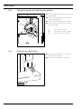
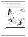
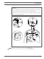
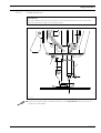
4
1
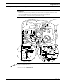
92-002
1.06
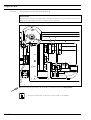
2
3
Fig. 1 - 01
Do not operate the machine without the take-up lever guard 1!
Danger of injury through the movement of the take-up lever.
Do not operate the machine without finger guard 2!
Danger of injury from the needle!
Do not operate machines with Quick-flange motor without start inhibitor 3!
Danger of injury if the machine is started accidentally!
When using an external motor do not operate the machine without belt guard 4!
Danger of injury from the drive belts!
1-4
Proper use
2
Proper use
The PFAFF 918 U is a high-speed zigzag sewing machine with bottom feed and large hook.
The PFAFF 938 U is a high-speed zigzag sewing machine with bottom feed.
The machines are used for producing zigzag lockstitch seams in the clothing and linen
industry.
Any use of these machines which is not approved by the manufacturer shall be
considered as improper use! The manufacturer shall not be liable for any damage arising out of improper use! Proper use shall also be considered to include
compliance with the operation, adjustment, service and repair measures specified by the manufacturer!
2 -1
Specifications
3
Specifications ▲
Stitch type: ........................................................................................ 304 (zigzag lockstitch)
Needle system: ............................................................................................................. 438
Needle size in 1/100 mm:
Model A: ...................................................................................................................60 - 70
Model B: ................................................................................................................. 80 - 100
Effective balance wheel diameter: ........................................................................... 65 mm
Presser foot clearance: .............................................................................................. 7 mm
Clearance width: .................................................................................................... 260 mm
Clearance height: ................................................................................................... 130 mm
Bedplate dimensions: ................................................................................... 476 x 177 mm
Sewing head dimensions:
Length: .............................................................................................................. ca. 550 mm
Width: ...............................................................................................................ca. 180 mm
Height (above table): ......................................................................................... ca. 300 mm
Max. stitch length
PFAFF 918-6/01: ...................................................................................................... 4,5 mm
PFAFF 938-6/01; -6/27: ............................................................................................ 2,5 mm
Max. speed
PFAFF 918: ................................................................................................... 5000 Sti/min ◆
PFAFF 938-6/01; -771/04-6/27: ...................................................................... 5500 Sti/min ◆
PFAFF 938-34/01 R: ...................................................................................... 6000 Sti/min ◆
Max. stitch with
PFAFF 918: ........................................................................................................... 10,0 mm
PFAFF 938-6/01: ...................................................................................................... 6,0 mm
PFAFF 938-771/04-6/27: .......................................................................................... 3,0 mm
PFAFF 938-34/01 R: ................................................................................................ 4,5 mm
Connection data:
Operating voltage: ...........................................................................230 V ± 10%, 50/60 Hz
Max. power ............................................................................................................. 1,2 kVA
Fuse protection: ............................................................................................ 1 x 16 A, inert
Noise data:
Noise emission level at workplace with a sewing speed of 4000 spm: ..... LpA < 80 dB(A) ■
(Noise measurement in accordance with DIN 45 635-48-A-1, ISO 11204, ISO 3744, ISO 4871)
Net weight of sewing head: .................................................................................. ca. 46 kg
Gross weight of sewing head: .............................................................................. ca. 54 kg
▲
Subject to alterations
◆
Depending on the stitch length, the maximum speed is reduced automatically within the max. pre-set value.
■
Kpa = 2.5 dB
3 -1
Disposal of Machine
4
Disposal of Machine
● Proper disposal of the machine is the responsibility of the customer.
● The materials used for the machine are steel, aluminium, brass and various plastic materials.
The electrical equipment comprises plastic materials and copper.
● The machine is to be disposed of according to the locally valid pollution control regulations; if necessary, a specialist ist to be commissioned.
Care must be taken that parts soiled with lubricants are disposed of separately
according to the locally valid pollution control regulations!
4-1
Transportation, packing and storage
5
Transportation, packing and storage
5.01
Transportation to customer's premises
The machines are delivered completely packed.
5.02
Transportation inside the customer's premises
The manufacturer cannot be made liable for transportation inside the customer's premises
nor to other operating locations. It must be ensured that the machines are only transported
in an upright position.
5.03
Disposal of packing materials
The packing materials of this machine comprise paper, cardboard and VCE fibre. Proper disposal of the packing material is the responsibility of the customer.
5.04
Storage
If the machine is not in use, it can be stored as it is for a period of up to six months, but It
should be protected against dust and moisture.
If the machine is stored for longer periods, the individual parts, especially the surfaces of
moving parts, must be protected against corrosion, e.g. by a film of oil.
5-1
Explanation of symbols
6
Explanation of symbols
In this instruction manual, work to be carried out or important information is accentuated by
symbols. These symbols have the following meanings:
Note, information
Cleaning, care
Lubrication
Maintenance, repairs, adjustment, service work
(only to be carried out by technical staff)
6 -1
Controls
7
Controls
7.01
Main switch
● The machine is switched on or off by
turning the main switch 1.
77-005
1
Fig. 7 - 01
Keys on the machine head (only on machines with Quick-flange motor)
● As long as key 1 is pressed during
sewing, the machine sews in reverse.
● Keys 2 and 3 can be allocated with
corresponding parameter settings, see
the Motor Instruction Manual.
3
2
1
04
7.02
Fig. 7 - 02
7-1
Controls
7.03
Pedal
0
=
Neutral position
1
=
Sewing
2
=
Raise presser foot
3
=
Trim thread
0
1
2
3
Fig. 7 - 03
7.04
Lever for raising presser foot
● The presser foot is raised by turning
lever 1.
1
Fig. 7 - 04
7-2
Controls
7.05
Adjustment lever for zigzag stitch and needle position
● The zigzag stitch adjustment lever 1 is
4
used for adjusting the width of the zigzag
stitch.
● To change the position of the adjustment
lever, the locking lever 2 must be
M
L
pressed against the adjustment lever 1.
R
3
The current zigzag-stitch width
can be seen on scale 3.
1
● By turning the needle-position
adjustment lever 4 the required needle
position can be set.
2
L = needle-position left
M = needle-position center
R = needle-position right
Fig. 7 - 05
7.06
Reverse-feed key
● The machine sews in reverse as long as
the reverse-feed key 1 is pressed.
1
Fig. 7 - 06
7-3
Controls
7.07
Stitch length adjustment wheel
● The stitch length can be adjusted by
turning the stitch length adjustment
wheel 1.
The stitch length setting can be
read on scale 2.
1
-008
2
Fig. 7 - 07
7.08
Adjustment lever of the underedge trimmer -771/04
● By pulling and turning lever 1 towards "+",
the underedge trimmer is switched on
and the knife stroke set.
Do not touch the knife while it
is running!
Danger of injury from the
moving knife.
1
Fig. 7 - 08
7-4
Controls
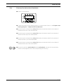
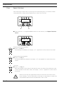
7.09
Control panel (only on machines with Quick-flange motor)
2
4
1
3
SPEED
TE
3
3
A
B
ERROR
3 3
C
D
The control panel consists of display 1 and the function keys described below. The display 1
consists of a single-line alpha-numerical, 7 segment LCD display with 8 symbols. The texts
2, located above and next to the LCD display, show the respective status of the function
keys and the operating status of the machine. The control panels switches on all LCDsegments and the horn automatically for a short time during the power-on phase, after
which the lettering PFAFF appears on the display, until the higher-ranking control unit sends
commands to the control panel.
The function keys are located around the display 1. They are foil-packed without permanent
marking and without contact signal. Fixed functions are allocated to the keys, see Chapter
7.09.02 Function keys.
7.09.01
Screen displays
● Activated functions are displayed with a triangular marking 3 below or next to the
respective function key.
● In the sewing mode all relevant sewing data is displayed and can be changed directly,
depending on the status of the machine, see also Chapter 10 Sewing.
● During the parameter input the selected parameter number with the corresponding value
is displayed, see Chapter 12.08.02 Example of a parameter input.
7.09.02
Function keys
The function keys described below are used basically to switch machine functions on and
off.
Each time a key is pressed, this must be confirmed by at least one beep tone. Irrespective
of the machine mode a double beep signal is given if invalid keys are pressed or maximum
values reached.
If a corresponding value has to be set for the activated function, this is carried out with the
corresponding +/- key. By pressing and holding the corresponding +/- key, the relevant
numerical value 4 is changed slowly to begin with. If the corresponding +/- key is held down
longer, the values change more quickly.
7-5
Controls
Start backtacks
● If this key is pressed, the backtacks at the beginning of the seam (start backtacks) are
switched on or off. The number of forward stitches (A) or reverse stitches (B) for the start
backtacks can be changed by pressing the +/- key underneath. To convert from double
backtack to single backtack set the number of stitches for the corresponding seam
section at zero.
End backtacks
● If this key is pressed, the backtacks at the end of the seam (end backtacks) are switched
on or off. The number of reverse stitches (C) or forward stitches (D) can be changed by
pressing the +/- key underneath. To convert from double backtack to single backtack set
the number of stitches for the corresponding seam section at zero.
Needle position
● If this key is pressed the "needle raised after sewing stop" function is switched on or off.
When the function is switched on, the needle positions at t.d.c. after sewing stops.
Foot position after stop
● If this key is pressed the "foot raised after sewing stop" function is switched on or off.
When the function is switched on, the presser foot is raised after sewing stops.
Foot position after trimming
● If this key is pressed the "foot raised after thread trimming" function is switched on or off.
When the function is switched on, the presser foot is raised after thread trimming.
Thread trimmer
● If this key is pressed the thread trimming function is switched on or off.
Darning program
● If this key is pressed the darning program function is switched on or off. The counted
seam function is switched off automatically.
Counted seam
● If this key is pressed the counted seam function is switched on or off. The darning
program function is switched off automatically.
TE/Speed
● If this key is pressed once the speed limit for the sewing mode is activated.
● If this key is pressed twice (within 5 seconds) the machine changes from sewing to input
mode.
7-6
Installation and commissioning
8
Installation and commissioning
The machine must only be installed and commissioned by qualified personnel!
All relevant safety regulations must be strictly adhered to!
If the machine is delivered without a table, be sure to use a stand and table top
that can hold the weight of the machine with its motor.
It is very important to ensure that the stand of the machine is firm and steady,
also during sewing.
8.01
Installation
The site where the machine is installed must be provided with suitable connections for electric current.
It must be ensured that the standing surface of the machine site is firm and horizontal, and
that sufficient lighting is provided for.
For packing and transportation reasons the table top is in the lowered position.
The table height is adjusted as described below.
Adjusting the table height
2
1
1
92-010
8.01.01
Fig. 8 - 01
● Loosen screws 1 and 2 and set the table height as required.
● Firmly tighten screw 1.
● Set the required pedal position and tighten screw 2.
8-1
Installation and commissioning
8.01.02
Mounting the upper V-belt guard / Fitting the machine cover
● Slide the left and right halves of the Vbelt guard into place with the slots
behind the heads of screws 1 and 2.
● Screw screw 3 with distance bush 4 into
threaded hole 5.
● Align the V-belt guard, taking care that
clip 6 is behind slot 7 and in front of
1
8
9
distance bush 4.
● Tighten screws 1 and 2 (through holes 8
2
6
81-007
5
and 9) and screw 3.
● When using an external motor, the motor
7
cover must also be fitted as described by
the motor manufacturer.
4
Fig. 8 - 02
8.01.03
3
Fitting the reel stand
● Fit the reel stand as shown in Fig. 8-03.
● Afterwards insert the stand in the hole in
the table top and secure it with the nuts
provided.
Fig. 8 - 03
8-2
Installation and commissioning
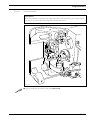
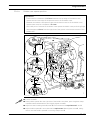
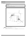
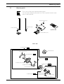
8.02
Fitting the Quick-flange motor.
5
8
7
3
6
2
4
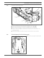
Fig. 8 - 04
1
● Loosen screws 1 and remove toothed belt wheel 2 from the motor shaft 3.
● Attach bearing plate 4 to the motor 5 with screws 6 as shown in Fig. 8-04.
● Slide toothed belt wheel 2 onto the motor shaft 3 and fasten with screws 1.
● Slightly tilt bearing plate 4 with motor 5 to the side and place the toothed belt 7 on the
toothed belt wheels.
● Align bearing plate 4 of motor 5 on the machine case and attach it with screws 8.
Fit the belt guard of the Quick flange-motor.
● Attach belt guard 1 with screws 2 and 3.
3
1
2
Fig. 8 - 05
92-050
8.03
8-3
Installation and commissioning
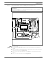
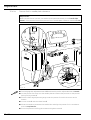
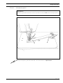
8.04
Connect the plug-type connections and earth cable of the Quick-flange motor.
7
6
A
8
B
1
2
7
3
5
90-004
4
Fig. 8 - 06
● Connect all the plugs 1-5 to the control box as labelled.
● Screw the earth cable from the sewing head and from main switch 6 to earth point A.
● Connect earth point A and earth point B with earth cable 7.
● Screw the earth cable 8 from the motor to earth point B.
8-4
Installation and commissioning
8.05
Commissioning
● Examine the machine, in particular the electric cables and pneumatic connection tubes
for any damage.
● Clean the machine thoroughly and then oil it.
● Have qualified personnel check whether the machine can be operated with the available
voltage and whether it is connected properly in the terminal box. If there are any
irregularities do not operate the machine under any circumstances.
● When the machine is running, the balance wheel must turn towards the operator, see
Chapter 8.07 Basic position of the machine drive unit.
● Connect the machine to the compressed air system. The pressure gauge should show a
pressure of 6 bar. If necessary, adjust the value, see Chapter 11.05 Checking/adjusting
the air pressure.
1
4
4
2
5
3
Fig. 8 - 07
Fig. 8 - 08
● Before commissioning the machine remove plug 1 from its hole and fill in oil up to
marking 2, see Chapter 11.02 Oiling the hook.
Plug 1 serves as a safety device for transportation and should not be used
during sewing operations.
● Before commissioning the machine remove screw 3 and fill in oil up to the marking
(inspection glass on the front side of the machine), see Chapter 11.03 Oiling the zigzag
drive.
8.06
Switching the machine on/off
● Switch the machine on, see Chapter 7.01 Main switch.
● Carry out a test run.
8-5
Installation and commissioning
8.07
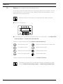
Basic setting of the machine drive unit (only on machines with Quick-flange motor)
● Switch on the machine.
2x
3
3
A
B
3 3
C
D
● Press TE/Speed key twice to call up the input mode.
TE
101 on
A
● By pressing the corresponding +/- key, call up parameter "798" and select service level
"C", see Chapter 12.08.01 Selecting the user level
TE
798
11
C
● By pressing the corresponding +/- key, call up parameter "800" (rotation direction of the
motor).
● By pressing the corresponding +/- key enter the value "1".
TE
800
1
C
● By pressing the corresponding +/- key select parameter "700".
8-6
Installation and commissioning
TE
700
0
C
● Sew one stitch by operating the pedal.
● Turn the balance wheel in the direction of sewing until the tip of the needle is level with
the top edge of the needle plate.
● By pressing the corresponding +/- key, select parameter "702".
TE
702
70
C
● By pressing the corresponding +/- key, enter the value "70".
● By pressing the corresponding +/- key, select parameter "703".
TE
703
222
C
● By pressing the corresponding +/- key, enter the value "222".
● Conclude the adjustment of the sewing motor by pressing the TE/Speed key.
The adjustment described above only applies to machines with Eco-Drive!
When using another type of motor, please observe the motor instruction
manual of the manufacturer.
8-7
Installation and commissioning
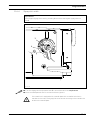
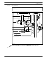
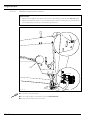
8.08
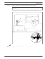
Mounting/connecting the start inhibitor (only on machines with Quick-flange motor)
1
92-015
2
3
6
Fig. 8 - 09
5
92-013
4
● For machines delivered without a table, the plate 1 from the accessories should be
mounted under the table top, so that the switch lug 2 is resting on plate 1 when the
sewing head is in an upright position.
● Loosen screws 3 and adjust switch 4 so that the switch lug 2 is free when the sewing
head is tilted back and pressed when the sewing head is upright.
● Connect plugs 5 and 6 to the switch 4.
Function check of the start inhibitor
ERROR
E
9
● Switch the machine on at the main switch and tilt it back.
The error message "E9" must appear on the control panel.
● If the message does not appear, check the setting of switch 4.
● Set the sewing head upright and acknowledge the error message by pressing the TE/
Speed key. The machine is ready for operation again.
8-8
Setting up
9
Setting up
All instructions and regulations in this instruction manual must be observed.
Special attention must be given to all safety regulations!
All setting-up work must only be done by personnel with the necessary
training. For all setting-up work the machine must be isolated from its power
supply by turning off the on/off switch or removing the machine plug from the
electric power socket!
9.01
Inserting the needle
Switch off the machine!
Danger of injury if the machine
is started accidentally!
Only use needles of system 438.
● Bring the needle bar into its highest
1
2
position.
● Loosen screw 1.
● Insert the needle 2 as far as possible.
● The long needle groove must be facing
forwards.
● Tighten screw 1.
Fig. 9 - 01
9-1
Setting up
9.02
Winding the bobbin thread; adjusting the primary thread tension
4
+
92-018
6
5
3
1
2
Fig. 9 - 02
● Place an empty bobbin 1 onto bobbin winder spindle 2.
● Thread the bobbin as shown in Fig. 9 - 02 and wind it clockwise around bobbin 1 a few
times.
● Switch on the bobbin winder while at the same time pressing bobbin winder spindle 2
and lever 3.
The bobbin is filled up during sewing.
● The thread tension on bobbin 1 can be adjusted using knurled screw 4.
● The bobbin winder stops automatically when bobbin 1 is full.
If the thread is wound unevenly:
● Loosen nut 5.
● Turn thread guide 6 accordingly.
● Tighten nut 5.
9-2
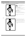
Setting up
9.03
Removing/inserting the bobbin case
Turn the machine off!
1
Removing the bobbin case.
● Lift clip 1 and remove bobbin case 2.
Inserting the bobbin case:
● Insert bobbin case 1 until you feel it click
into place.
2
Fig. 9 - 03
11-04
9.04
Threading the bobbin case, adjusting the thread tension
9.04.01
PFAFF 938 without thread trimmer
● Insert bobbin 1 into bobbin case 2.
● Guide the thread through the slot under
spring 3.
1
5 cm
● Adjust the thread tension by turning
screw 4.
When the thread is pulled the
bobbin 1 must rotate in the
direction of the arrow.
3
_
+
2
4
Fig. 9 - 04
9-3
Setting up
9.04.02
PFAFF 938 with thread trimmer
● Insert bobbin 1 into bobbin case 2.
● Guide the thread through the slot under
spring 3.
● Adjust the thread tension by turning
screw 4.
1
5 cm
When the thread is pulled the
bobbin 1 must rotate in the
direction of the arrow.
92-055
3
__
4
+
+
2
Fig. 9 - 05
9.04.03
PFAFF 918
● Pull the thread through the slot under the
5 cm
spring as shown in the opposite
illustration.
● Adjust the thread tension by turning
screw 1.
When the thread is pulled, the
bobbin 1 must turn in the
direction of the arrow.
1
Fig. 9 - 06
9-4
Setting up
Threading the needle thread / Adjusting the needle thread tension
1
+
m
6c
92-019
9.05
Fig. 9 - 07
Switch off the machine!
Danger of injury if the machine is started accidentally!
● Thread the needle thread as show in the above illustration.
● Adjust the needle thread tension by turning milled screw 1.
9-5
Setting up
9.06
Setting the zigzag stitch and the stitch position
● Set the zigzag stitch width by turning the
zigzag lever 1.
● To vary the adjustment press catch 2
4
M
L
against zigzag lever 1.
● The setting can be read from scale 3.
R
● Set the stitch position by turning stitch
position lever 4.
3
L =
M =
R =
1
stitch position on left
stitch position in the middle
stitch position on the right
2
Fig. 9 - 08
9.07
Adjusting the stitch length
● Adjust the stitch length by turning the
feed regulator wheel 1.
● The setting can be read on scale 2.
1
92-008
2
Fig. 9 - 09
9-6
Setting up
9.08
Entering the start and end backtacks
● Switch on the machine.
3
3
A
B
3 3
C
D
● If necessary switch off the "darning seam" or "counted seam" function, see Chapter 10.01
Darning program or Chapter 10.02 Counted seam.
● By pressing the corresponding +/- key ("A") select the desired value for the number of
forward stitches (A) of the start backtack.
● By pressing the corresponding +/- key ("B") select the desired value for the number of
reverse stitches (B) of the start backtack.
● By pressing the corresponding +/- key ("C") select the desired value for the number of
reverse stitches (C) of the end backtack.
● By pressing the corresponding +/- key ("D") select the desired value for the number of
forward stitches (D) of the end backtack.
● By pressing the keys start backtack and/or end backtack, activate the corresponding
function (arrow appears next to the corresponding function key).
9-7
Sewing
10
Sewing (only on machines with Quick-flange motor)
In the sewing mode all relevant settings for the sewing operation are displayed. Functions
can be switched on or off by pressing a key. Values for start and end backtacks or stitch
placement can be changed directly.
When the machine is switched on, the sewing mode is always activated.
● Switch on the machine.
3
3
A
B
3 3
C
D
● If necessary switch off the function "darning seam" or "counted seam", see Chapter 10.01
Darning program or Chapter 10.02 Counted seam.
Functions in manual sewing, also see Chapter 7.09.02 Function keys:
Start backtacks on/off
Presser foot raised at end of seam on/off
End backtacks on/off
Thread trimming on/off
Needle position raised on/off
Darning program on/off
Presser foot raised on/off
Counted seam on/off
Sewing is carried out with the pedal functions, see Chapter 7.03 Pedal..
The "Darning program" and "Counted seam" functions are explained in more
detail in Chapter 10.01 Darning program or Chapter 10.02 Counted seam.
10 - 1
Sewing
10.01
Darning program
15 15 5 1
A
B
C
1
The corresponding function can be switched on or off directly with the Darning program
key. The "counted seam" function is switched off automatically. Several darning programs
with different seam sections A and/or B can be selected. The number of required darning
programs can be selected by operating the +/- key 1. The number of stitches for the individual seam sections A and/or B can be selected by operating the corresponding +/- key. By
operating the corresponding +/- key it is possible to select a repeating factor "C" for the
selected darning program.
If the backtack functions are also activated, only the status backtack on or backtack off is
displayed. The individual backtack parameters can be altered after the "darning program"
function has been switched off, see Chapter 9.08 Entering start and end backtacks.
10.02
Counted seam
160
1
A
1
The corresponding function can be switched on or off directly with the Counted seam key.
The "darning program" function is switched off automatically. Several counted seam sections
can be selected. The number of required seam sections can be selected by operating the
+/- key 1. The required number of stitches"A" of the selected seam section can be selected
by operating the corresponding +/- key.
If the backtack functions are also activated, only the status backtack on or backtack off is
displayed. The individual backtack parameters can be altered after the "counted seam"
function has been switched off, see Chapter 9.08 Entering start and end backtacks.
10 - 2
Sewing
10.03
Error messages
If a fault occurs, the text "ERROR" appears on the display, together with an error code and
short instructions. An error message is caused by incorrect settings, faulty elements or
seam programs as well as by overload conditions.
For an explanation of the error codes see Chapter 12.10 Explanation of the error
messages.
ERROR
E
9
● Correct the error.
● Acknowledge error correction by pressing the TE/Speed key.
10 - 3
Care and maintenance
11
Care and maintenance
Cleaning ....................................................... daily, several times by continuous operation
Checking the oil level (hook oil tank) ............................................................. once a year▲
Checking the oil tank(zigzag eccentric lubrication) .......................... daily, before operation
Checking/adjusting the air pressure ....................................... daily, before each operation
Cleaning the air filter/lubricator .......................................... Cleaning the air filter/lubricator
▲
This maintenance interval if for an average machine running time in a single
shift operation. If the machine running times are longer, shorter maintenance
intervals are recommended.
11.01
Cleaning
Switch off the machine!
Danger of injury if the machine is started accidentally!
● Tilt back the machine head.
● Clean the hook and the hook
compartment daily, more often if in
continuous operation.
Use both hands to set the
machine upright!
Danger of crushing between
sewing head and table top!
Fig. 11 - 01
11 - 1
Care and maintenance
11.02
Lubricating the hook
2
3
1
Fig. 11 - 02
Fig. 11 - 03
Turn the machine off!
Danger of injury if the machine is started accidentally!
Only use oil with a mean viscosity of 10.0 mm2/s at 40°C and a density of
0.847 g/cm3 at 15°C.
● Lay the machine head on its back.
● Fill the oil reservoir 1 up to the upper marking 3 through hole 2.
● Before operating the machine for the first time or after longer stationary periods,
add a few additional drops of oil into the hook race (see arrow in Fig. 11-03).
Return the machine to its upright position with both hands. Danger of crushing
between machine head and table top!
We recommend PFAFF sewing machine oil.
Part no. 280-1-120 105.
11 - 2
Care and maintenance
11.03
Oiling the zigzag drive
4
4
5
2
1
3
Fig. 11 - 04
Fig. 11 - 05
Switch off the machine!
Danger of injury if the machine is started accidentally!
Only use oil with a mean viscosity of 68.00 m2/s at 40° C and a density of
0.881 g/cm3 at 15° C.
● Check the oil level before each operation.
● If necessary, remove screw 1 and fill in oil up to top marking 2.
● Tighten screw 1.
Never allow the oil level to sink below the minimum mark 3!
Danger of damage to the machine!
To fill in larger quantities of oil, e.g. when filling for the first time before
commissioning, it is better to remove cover 5.
● Loosen screws 4 and remove cover 5.
● Take care that no dirt gets into the case.
● Fill in oil up to the top marking 2.
● Clean the surface of cover 5, the case and the seal.
● Replace cover 5 and tighten screws 4.
We recommend PFAFF sewing machine oil, part no. 280-1-120 146.
11 - 3
Care and maintenance
11.04
Cleaning the air filter of the air-filter / lubricator
Switch the machine off!
Disconnect the air hose at the
air-filter / lubricator.
To drain water bowl 1:
● Water bowl 1 drains itself automatically
when the compressed-air hose is
disconnected from the air-filter / lubricator.
8
10
6
100
150
4
12
50
200
2
14
230
0
16
0
Cleaning filter 2:
● Unscrew water bowl 1.
● Take out filter 2.
● Clean filter 2 with compressed air or
isopropyl alkohol ( part No. 95-665 735-91
).
● Screw in filter 2 and screw on water
bowl 1.
2
1
Fig.A 11 - 06
11.05
Checking/adjusting the air pressure
● Before operating the machine, always
check the air pressure on gauge 1.
2
● To do so, pull knob 2 upwards and turn it
so that the gauge shows a pressure of
8
10
6
100
4
150
12
50
200
2
0
0
1
Fig. 11 - 07
11 - 4
14
230
16
● Gauge 1 must show a pressure of 6 bar.
● If necessary adjust to this reading.
6 bar.
Adjustment
12
Adjustment
12.01
Notes on adjustment
All following adjustments are based on a fully assembled machine and may only be carried
out by expert staff trained for this purpose.
Machine covers, which have to be removed and replaced to carry out checks and
adjustments, are not mentioned in the text.
The order of the following chapters corresponds to the most logical work sequence for
machines which have to be completely adjusted. If only specific individual work steps are
carried out, both the preceding and following chapters must be observed.
Screws, nuts indicated in brackets ( ) are fastenings for machine parts, which must be
loosened before adjustment and tightened again afterwards.
The machine must be switched off for all adjustment work!
Danger of injury if the machine is started accidentally!
12.02
Tools, gauges and other accessories for adjusting
● 1 set of screwdrivers with blade widths from 2 to 10 mm
● 1 set of wrenches with jaw widths from 7 to 14 mm
● 1 set of Allan keys from 1.5 to 6 mm
● 1 metal rule, (Part No. 08-880 218-00)
● Locking pin (5 mm diameter), part no. 13-030 341-05
● Feed dog adjustment gauge, part no. 91-119 995-05
● Hook bearing adjustment gauge, part no. 91-119 996-05
● Needles, threads and test material
12.03
Abbreviations
TDC = top dead center
BDC = bottom dead center
12 - 1
Adjustment
12.04
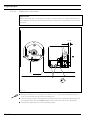
Check and adjustment aid
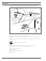
By blocking with holes 1 - 5 the required needle bar positions can be fixed
exactly.
4
81-016
3
1
2
92-021
5
Fig. 12 - 01
● Turn the balance wheel until the needle bar has approximately reached the required
position.
● Place the 5 mm blocking pin in the appropriate hole and put pressure on it.
● Turn the balance wheel forwards and backwards a little until the blocking pin moves
into the slot in the crank behind the bearing plate, thus blocking the machine.
Hole 1
Hole 2
Hole 3
Hole 4
Hole 5
12 - 2
=
=
2.0 mm after the bottom dead center of the needle bar (2.0 past tdc)
Top dead center of the needle bar (tdc)
=
=
0.25 mm after the top dead center of the needle bar (0.25 past bdc)
1.0 mm after the top dead center of the needle bar (1.0 mm past tdc)
=
4 mm after the bottom dead center of the needle bar (4.0 past bdc)
Adjustment
12.05
Adjusting the basic machine
12.05.01
Balancing weight
Requirement
With the needle bar at bdc the largest eccentricity of the balancing weight 1 must be
pointing upwards.
1
81-060
2
Fig. 12 - 02
● Bring the needle bar to b.d.c.
● Adjust the balance weight 1 (screw 2) in accordance with the requirement.
12 - 3
Adjustment
12.05.02
Centering the needle in the needle hole (in sewing direction)
Requirement
With the zigzag setting at "0" and the needle position set at "middle" the needle must
enter the center of the needle hole as viewed in the direction of sewing.
2
1
81-061
3
92-023
Fig. 12 - 03
● Bring the needle bar to b.d.c.
● Adjust the eccentric pin 1 (nut 2 and screw 3) in accordance with the requirement.
12 - 4
Adjustment
Parallel guiding of the needle bar
81-018
Requirement
Guide bar 5 must be parallel to the needle bar.
2
3
4
6
4
3
81-019
12.05.03
1
2
5
5
1
Fig. 12 - 04
● Bring the needle bar to tdc (hole 2).
● Loosen screws 1,2 and nut 3.
● The largest eccentricity of pin 4 must be facing downwards.
● Bring the groove on guide bar 5 into a position in which it rests against eccentric pin 4,
turn eccentric pin 4 in accordance with the requirement and tighten nut 3.
● Push guide bar 5 downwards and then upwards as far as possible. Bushing 6 must not
move laterally during this movement (readjust eccentric pin 4 if necessary).
● Move guide bar 5 until it rests against eccentric pin 4 and tighten screws 1 and 2.
12 - 5
Adjustment
12.05.04
Locking lever
Requirement
The zigzag stitch adjustment lever 3 must be able to be locked in any position.
2
01
2 3
45
6
4
1
3
Fig. 12 - 05
● Loosen screw 2.
● Press locking lever 1 against the zigzag stitch adjustment lever 3.
● Turn pivot pin 4 as far as possible to the left.
● Release locking lever 1.
● Locking lever 1 must be parallel to the zigzag stitch adjustment lever 3.
● Tighten screw 2.
12 - 6
Adjustment
12.05.05
Zero stitch and zigzag stitch scale
Requirement
With the zigzag stitch set at "0":
1. the needle bar must not move laterally when the balancewheel is turned and
2. the marking "0" on scale 1 must be at marking 2.
4
7
1
2
7
3
6
5
Fig. 12 - 06
● Set the needle position adjustment lever 4 to "middle" and loosen screws 5 and 6.
● Run the machine slowly and turn the zigzag stitch adjustment lever 3 to the right until
the needle bar no longer moves laterally.
● Turn the machine off. Move screw 5 to the right until it touches and then tighten it.
● Loosen screws 7 and move scale 1 in accordance with requirement 2.
● Tighten screws 7.
Screw 6 remains loose for the following adjustment.
12 - 7
Adjustment
12.05.06
Centering the needle in the needle hole (crosswise to sewing direction)
Requirement
With the zigzag stitch set at "0" and the needle position setting at "middle" the needle
must enter the center of the needle hole as seen across the direction of sewing.
2
81-062
1
92-022
Fig. 12 - 07
● Adjust the eccentric pin 1 (nut 2) in accordance with the requirement.
12 - 8
Adjustment
12.05.07
Zigzag stitch width
Requirement
At the largest zigzag stitch setting, marking 1 must be at the largest zigzag value on
scale 2.
2
1
4
3
Fig. 12 - 08
● Turn the zigzag stitch adjustment lever 3 in accordance with the requirement.
● Move screw 4 upwards until it touches and then tighten it.
If the machine is equipped with a needle plate with a smaller hole than is
marked on the scale, the zigzag limit must be set according to the needle hole
width on the needle plate.
12 - 9
Adjustment
12.05.08
Zigzag stitch movement
Requirement
When the needle bar, on the right of its throw, is positioned at t.d.c. (adjustment hole "2"),
the needle bar should not move laterally when the zigzag stitch adjustment lever is moved
to and fro.
5 mm
4
81-019
3
1
2
5
2
1
Fig. 12 - 09
● Bring the needle bar, on the right of its throw, to t.d.c. and place the adjustment pin in
hole "2" of the bearing plate (locking the machine).
● Turn the zigzag eccentric 1 (screws 2) in accordance with the requirement. Make sure that
he zigzag eccentric 1 is about 5 mm away from the right inner side of the casting wall.
● Remove the adjustment pin from the bearing plate.
12 - 10
Adjustment
12.05.09
Needle penetration symmetry (left, centre and right)
Requirement
When the zigzag stitch is set at "0", the needle should penetrate in the centre of the needle
hole. With the maximum zigzag stitch set, the needle should penetrate on the left and right
at the same distance from the centre hole.
2
1
Fig. 12 - 10
● Let the needle penetrate in the required zigzag settings using paper.
● Without twisting it adjust zigzag eccentric 1 (screws 2) in accordance with the
requirement.
12 - 11
Adjustment
12.05.10
Needle position adjustment lever
Requirement
The left and right throws of the needle must be the same size at the largest zigzag stitch
setting and at the left or right needle position.
3
1
2
4
Fig. 12 - 11
● Loosen screws 1 and 2.
● Set the needle position adjustment lever 3 to "middle" and the zigzag stitch adjustment
lever 4 at the largest zigzag stitch.
● Place a piece of paper underneath the presser foot and perforate it to the left and right
with the needle.
● Set the zigzag stitch adjustment lever 4 at "0" and move the needle position adjustment
lever 3 to the right/left until the needle is exactly over the perforations made in the last step.
● For the left needle-position bring screw 1 to a position where it touches and tighten it
and for the right needle-position do the same with screw 2.
12 - 12
Adjustment
Zero position of the bottom feed dog (with closed gear box)
Requirement
With the stitch length set at "0", the bottom feed dog should not carry out any feeding
motion when the balance wheel is turned.
1
5
2
4
3
92-032
12.05.11
Fig. 12 - 12
● Loosen screw 1.
● Fit the fork wrench (SW 27) to the spring clamp ring 2 using it to hold the regulating
shaft 3.
● While continually turning the balance wheel, adjust the fork wrench on the spring clamp
ring 2 in accordance with the requirement.
● In this position move adjusting crank 4 and ring 5 against the metal frame and tighten
screw 1.
● Carry out a check in accordance with the requirement.
12 - 13
Adjustment
12.05.12
Zeroing the bottom feed (with open gearbox)
Requirement
With the stitch length set at "0" the bottom feed dog must not carry out any feeding
motion when the balance wheel is turned.
1
2
3
Fig. 12 - 13
● Switch on the machine.
● While continuously turning the balance wheel, adjust reversing crank 1 (screw 2) in
accordance with the requirement.
● Switch off the machine.
12 - 14
Adjustment
Feeding motion of the bottom feed dog
Requirement
With the maximum stitch length set and the needle bar position 1.0 past tdc (hole 4), the
bottom feed dog must not move when the reverse feed lever is pressed.
1
2
81-063
12.05.13
Fig. 12 - 14
● While continuously operating the reverse feed control, adjust feeding eccentric 1
(screws 2) in accordance with the requirement (the counter-sinking in feeding
eccentric 1 must be visible).
An axial displacement of feeding eccentric 1 is not allowed.
12 - 15
Adjustment
12.05.14
Lifting motion of the bottom feed dog
Requirement
With the stitch length set at "0" and the needle bar position at 0.25 mm past tdc (hole 3)
the bottom feed dog must be at its upper point of reversal.
1
81-064
2
Fig. 12 - 15
● Adjust feed lifting eccentric 1 (screw 2) in accordance with the requirement.
An axial displacement of feed lifting eccentric 1 is not allowed.
12 - 16
Adjustment
12.05.15
Drive belt in the gearbox housing
Requirement
Drive belt 4 must be tightened so that the machine runs freely and the belt sprockets
do not have any noticeable play.
4
3
1
2
Fig. 12 - 16
● Adjust eccentric bearing bush 1 (screw 2) in accordance with the requirement and so
that drive belt 4 is in the centre of bobbin opener drive wheel 3.
12 - 17
Adjustment
12.05.16
Hook bearing bracket
Requirement
The hook shaft must be touching the hook bearing bracket adjustment gauge 1 at the top
and the side.
1
2
438 - 439
81-075
418 - 419
1
81-076
4
3
Fig. 12 - 17
● Loosen screw 3.
● Swing the bobbin case opener to the right and remove the hook.
● Loosen screw 2 and loosen the draw key underneath it by lightly tapping the head of
the screw.
● Screw on the hook bearing bracket adjustment gauge.
● It must be possible to read the numbers "438-439" from the front.
● Move or turn hook bearing bracket 4 in accordance with the requirement.
● Tighten screw 2.
● Adjust the bobbin case opener in accordance with subsection 12.05.21 Bobbin case
opener position.
12 - 18
Adjustment
12.05.17
Hook lubrication
Requirement
When the machine is running at full speed, after about 10 seconds a fine oil streak should
be visible on a strip of paper held over the needle plate cutout.
1
Fig. 12 - 18
● Adjust screw 1 in accordance with the requirement.
12 - 19
Adjustment
12.05.18
Pre-adjusting the needle height
Requirement
With the needle bar at tdc (hole 2) the distance between the point of the needle and the
needle plate must be 19 mm.
4
81-019
3
1
2
5
81-079
1
19 mm
Fig. 12 - 19
● Without turning it, adjust the needle bar (screws 1) in accordance with the requirement.
12 - 20
Adjustment
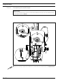
Needle rise, hook-to-needle clearance and bobbin case positioning-finger
Requirement
1. With the needle position set at "middle", the zigzag stitch setting at "0" and the needle bar
position 2.0 past bdc (hole 1) the hook point must be in the middle of the needle and the
distance between the needle and the hook point must be 0.05 - 0.1 mm.
2. The bobbin case positioning-finger must be fitted so that there is a clearance of 0.5
mm between the bottom section of the bobbin case and the front edge of the bobbin
case positioning-finger (see arrow).
81-065
0.5 mm
0.05 - 0.1 mm
1
81-067
81-066
12.05.19
Fig. 12 - 20
● Adjust the hook (screw 1) in accordance with requirement 1.
● Fit the bobbin case position stop in accordance with requirement 2.
12 - 21
Adjustment
12.05.20
Final adjustment of the needle height
Requirement
With the zigzag stitch set at "0", the needle position set at "left" and the hook point in the
middle of the needle, the top edge of the needle eye must be 0.5 mm underneath the
hook point.
81-081
0.5 mm
1
Fig. 12 - 21
● Without turning it, adjust the needle bar (screws 1) in accordance with the requirement.
12 - 22
Adjustment
Bobbin case opener position
81-068
Requirement
1. There must be a clearance of 0.5 mm between the top edge of the bobbin case
opener and the inner edge of the bottom section of the bobbin case.
2. Between the bobbin case opener finger and the bottom section of the bobbin case
opener there must be a clearance of 0.8 mm.
3. At the left point of reversal of the bobbin case opener the bobbin case positioning-finger
must be approx. 0.3 mm from the right side of the groove in the bottom section of the
bobbin case.
0.5 mm
0.8 mm
81-069
1
2
3
0.3 mm
81-070
4
5
92-035
12.05.21
Fig. 12 - 22
● Loosen screw 2.
● Place bobbin opener 1 on the right side of the bobbin case base, press it against clamp
crank 3 located underneath this and slightly tighten screw 2.
● Adjust eccentric bearing bush 4 (screw 5) in accordance with requirements 1 and 2.
● Adjust bobbin opener 1 in accordance with requirement 3 and tighten screw 2, taking
care to see that bobbin opener 1 is touching clamp crank 3
12 - 23
Adjustment
12.05.22
Bobbin case opener motion
Requirement
With the needle bar 2.0 past bdc (hole 1) the bobbin case opener 3 must be at its right
point of reversal.
1
3
81-073
2
Fig. 12 - 23
● Adjust bobbin opener eccentric 1 (screws 2) in accordance with the requirement.
12 - 24
Adjustment
Bottom feed dog height
Requirement
With the stitch length set at "0" and the needle bar position at 0.25 past tdc (hole 3) the
bottom feed dog must be in the middle of the needle plate cutout and be touching the
feed dog height-adjustment gauge along its entire length.
1
2
1.1 mm
12.05.23
3
4
81-102
Fig. 12 - 24
● Position the feed dog adjustment gauge underneath the presser foot with the cutout
facing downwards.
● Lower the presser foot onto it.
● Press the feed dog carrier up and position the feed dog in the middle of the needle plate
cutout.
● Adjust lifting crank 1 (screws 2) and clamp bushing 3 (screws 4) in accordance with the
requirement.
12 - 25
Adjustment
12.05.24
Presser foot to needle plate clearance
Requirement
When the hand lever is raised, the needle should penetrate exactly in the "needle hole
centre" of the presser foot and the presser foot to needle plate clearance should be 7 mm.
3
81-036
2
5 mm
1
81-038
Fig. 12 - 25
● Set the zigzag stitch adjustment lever at "0" and the stitch position adjustment lever at "centre".
● Let the presser foot drop onto the needle plate and reduce the pressure on the presser
bar by turning screws 1.
● Place the feed dog adjustment gauge under the presser foot with the recess at the
bottom.
● Loosen screw 2 and raise hand lever 3.
● Allow the needle to penetrate the needle hole and align the presser foot in accordance
with the requirement.
● Press the presser bar lifting piece down and tighten screw 2.
12 - 26
Adjustment
12.05.25
Needle thread tension release (on machines without -900/24)
Requirement
When the hand lever is raised, the tensions disks should be at least 0.5 mm apart.
1
4
2
3
0.5 mm
3
Fig. 12 - 26
● Loosen screw 1 and press linkage rod 2 down as far as possible.
● Raise the presser foot.
● Adjust trip 3 (screw 4) in accordance with the requirement.
12 - 27
Adjustment
12.05.26
Presser foot pressure
Requirement
Even at top sewing speed the material should be fed without problems. There should be
no pressure marks on the material.
+
-
1
Fig. 12 - 27
● Turn screw 1 in accordance with the requirement.
The presser foot pressure (screw 1) can be increased (+) or reduced (-) as
required.
12 - 28
Adjustment
Thread diverter pin
Requirement
With the needle bar at bdc the top edge of the thread guide hole must be at the same
height as the bottom edge of the thread diverter.
2
1
92-040
12.05.27
Fig. 12 - 28
● Adjust thread guide bar 1 (screw 2) according to the requirement, taking care that it is
parallel to the bed-plate.
12 - 29
Adjustment
12.05.28
Limiting the knee lever stroke
Requirement
When the knee lever is pressed the hand lever must drop automatically and the presser
foot must be just over 7 mm above the needle plate.
2
7 mm
92-041
1
81-038
Fig. 12 - 29
●
●
●
●
Place the feed dog gauge under the presser foot with its recess facing downwards.
Lower the presser foot onto the gauge.
Loosen nut 1 and turn screw 2 out a few turns.
Move the knee lever to the right until a noticeable resistance is felt, making sure that the
presser foot is not lifted off the gauge, and hold it at this position.
● Turn screw 2 in as far as it will go, then back out by one turn, and lock it in place with
nut 1.
12 - 30
Adjustment
Knee lever play
Requirement
When lightly pressing the knee lever there should be a noticeable play between nut 1 and
fork 3.
3
1
2
92-042
12.05.29
Fig. 12 - 30
● Adjust nut 1 (nut 2) in accordance with the requirement and lock it with nut 2.
12 - 31
Adjustment
12.05.30
Bobbin winder
Requirement
1. With the bobbin winder engaged the bobbin winder spindle must be turned reliably,
but friction wheel 3 must not touch drive wheel 1 when the bobbin winder is
switched off.
2. The bobbin winder must disengage automatically when the thread is approx. 1 mm
from the edge of the bobbin.
1
3
1 mm
2
5
4
Fig. 12 - 31
● Position drive wheel 1 in accordance with requirement 1 and tighten screw 2.
● Place a bobbin onto the bobbin winder, thread the bobbin and engage the bobbin winder
● Move regulating pin 3 in accordance with requirement 2 and tighten screw 4.
12 - 32
Adjustment
12.06
Adjusting the underedge trimmer -771/04
12.06.01
Resting position of the knife
Requirement
When adjustment lever 1 is set at "0", the knife stroke should be as small as possible.
1
4
2
65 mm
6
5
3
90°
1
4
9
8
7
Fig. 12 - 32
● Unscrew the milled screw of adjustment lever 1 (screw 2).
● Remove cover 3 (screws 4).
● Place crank 5 (screws 6) at right angles to the bed plate, and at the same time set a
distance of 65 mm between adjustment lever 1 and the bedplate.
● Screw cover 3 (screws 4) back on.
● Set adjustment lever 1 at "0".
● Remove cover cap 7 and check the lifting motion of the knife by turning the motor
impeller wheel (see requirement).
● Adjust crank 8 (screw 9) in accordance with the requirement.
12 - 33
Adjustment
12.06.02
Knife height
Requirement
When the adjustment lever 1 is set at "0" and the knife is at the top of its stroke, the top
edges of the needle plate and knife should be at the same level.
1
3
4
2
Fig. 12 - 33
● Set adjustment lever 1 at "0".
● Remove cover cap 2 and turn the motor impeller wheel until the knife is positioned at its
t.d.c.
● Adjust linkage rod 3 (screw 4) in accordance with the requirement.
12 - 34
Adjustment
12.06.03
Positioning of the knife
Requirement
The knife should be touching the counter blade and be positioned at a slight slant to the
stationary knife.
1
2
Fig. 12 - 34
● Adjust eccentric 1 (screw 2) in accordance with the requirement.
12 - 35
Adjustment
12.06.04
Knife drive switch
Requirement
When the adjustment lever 1 is set at "0", the knife drive unit must be switched off, and
from position "1" on it must be switched on.
4
2
3
1
Fig. 12 - 35
● Set adjustment lever 1 at "0".
● Turn lever 2 (screw 3) until it pushes switch 4.
● Set adjustment lever 1 at "1".
● Check the setting in accordance with the requirement, and adjust lever 2 if necessary.
12 - 36
Adjustment
12.06.05
Workpiece guard
Requirement
Workpiece guard 1 should be as close as possible to the knife 3 and be touching stop 4.
3
2
1
4
Fig. 12 - 36
● Adjust workpiece guard 1 (screws 2) in accordance with the requirement.
12 - 37
Adjustment
12.07
Adjusting the thread trimmer -900/24
12.07.01
Axial position of the control cam
Requirement
1. Roller 5 should be at a distance of 0.3 mm from the control cam 1.
2. Adjustment ring 3 should be touching the control cam 1.
1
2
3
4
5
0.3 mm
92-043
81-048
Fig. 12 - 37
● Shift control cam 1 (screw 2) and adjustment ring 3 (screw 4) in accordance with the
requirements.
12 - 38
Adjustment
Preliminary adjustment of the control cam
Requirement
1. In the needle rise position (hole 1) the roller lever 4 should lock into the corresponding
groove of the control cam.
2. The control cam 1 should be touching adjustment ring 3.
1
2
3
4
81-049
92-043
12.07.02
Fig. 12 - 38
● Turn control cam 1 (screws 2) in accordance with requirement 1 and shift it in
accordance with requirement 2.
12 - 39
Adjustment
12.07.03
Position of the thread catcher and cutting test
Requirement
When the thread trimmer is in its neutral position, the edge of thread catcher 6 should be
flush with the edge of the mounting plate 4.
4
3
6
1
3
2
81-100
92-044
5
Fig. 12 - 39
● Turn linkage rod 1 (nuts 2, left and right thread) in accordance with the requirement.
● During the cutting test, remove linkage rod 1, loosen screws 3 and remove mounting
plate 4.
● Carry out the cutting test with double thread.
● By turning screw 5 adjust the cutting pressure.
● Fit mounting plate 4 so that its edge is flush with the edge of the bed-plate.
● Tighten screws 3 and replace linkage rod 1.
12 - 40
Adjustment
Readjustment of the control cam
Requirement
1. When the end of the hook guard 3 is level with of the right edge of the bobbin case
position finger 4, the thread catcher 5 should begin moving forwards.
2. The control cam 1 should be touching adjustment ring 6.
5
2
1
6
81-044
3
4
92-045
12.07.04
81-098
Fig. 12 - 40
● Bring the needle bar to b.d.c.
● Turn control cam 1 (screws 2) in accordance with requirement 1 and shift it in
accordance with requirement 2.
12 - 41
Adjustment
12.07.05
Needle thread tension release
Requirement
1. When solenoids 3 are activated, the tensions disks 4 should be at least 0.5 mm apart.
2. When the thread trimmer is in its neutral position and the sewing foot is positioned on
the needle plate, the tension should be fully effective.
1
2
92-047
3
0.5 mm
4
● Unscrew the thread wiper.
● Turn nut 1 (nut 2) in accordance with the requirements.
● Screw thread wiper back into place.
12 - 42
92-013
57-05
Fig. 12 - 41
Adjustment
12.08
Parameter settings
12.08.01
Selecting the user level
● Switch on the machine.
2x
3
3
A
B
3 3
C
D
● Press the TE/Speed key twice to call up the input mode.
TE
101
on
A
● By pressing the corresponding +/- key select the parameter group "798".
TE
798
0
A
● By pressing the corresponding +/- key select the desired user level:
"0"
"1"
=
=
"11" =
operator level A
technician level B
service level C
The selected user level is displayed on the screen. (see arrow)
12 - 43
Adjustment
12.08.02
Example of a parameter input
● Switch on the machine.
2x
● Press the TE/Speed key twice to select the input mode.
TE
101 on
A
B
C
D
● By pressing the corresponding plus/minus key select parameter "798" and the user level
"B", see Chapter 12.08.01 Selecting the user level.
TE
798
1
B
● Select parameter "607" by pressing the corresponding +/- key.
TE
607
4500
B
● Select the required value for the maximum speed by pressing the corresponding +/- key.
● By pressing the TE/Speed key the selected value is taken over and the machine switches
to the sewing mode.
12 - 44
Adjustment
A, B, C
ON
6
605
Speed display
(0FF = AUS, ON = EIN)
B, C
OFF
607
Max. speed
B, C
300 - 6000
4500
609
Cutting speed
B, C
60 - 500
180
660
Bobbin thread control
0 = off
1 = thread monitor
2 = reverse counter
A, B, C
0-2
0
700
Needle position 0
(needle reference position)
B, C
0 - 255
702
Needle position 1 (needle lowered)
B, C
0 - 255
70
703
Needle position 2 (take-up lever raised)
B, C
0 - 255
222
705
Needle position 5 (end of cutting signal 1)
B, C
0 - 255
196
706
Needle position 6 (start of cutting signal 2)
B, C
0 - 255
136
707
Needle position 9
(start thread tension release)
B, C
0 - 255
150
797
Hardware test
(0FF = AUS, ON = EIN)
B, C
798
User level
0 = User level "A"
1 = Mechanic level "B"
11 = Service level "C"
A, B, C
0, 1, 11
0
799
Machine class
1 = 918 / 938
2=-
C
1-2
1
800
Rotating direction of the motor
1 = 918 / 938
C
0-1
1
7
8
Set value
Control panel key tone
(0FF = AUS, ON = EIN)
range
101
Setting
1
User level
Parameter
Description
List of parameters
Group
12.08.03
OFF
Further parameters are listed in the Motor Instruction Manual.
12 - 45
Adjustment
Reset / Cold start
12.09
After selecting the reset menu, by pressing the corresponding key it is possible to delete
seam parameters, delete seam programs and to carry out a cold start.
A
D
● Press and hold "+" on keys A and D and switch on the machine, see Chapter 7.01 Main
switch.
1_ 2 _ _ _ 3 _
A
A
B
D
Resetting the seam parameters
● Press "+"on key "A".
All parameters are deleted, the display "—rE—" appears for a short time on the screen.
B
Resetting the seam programs
● Press "+"on key "B".
All seam programs are deleted, the display "—rE—nA" appears for a short time on the
screen.
D
Cold start
● Press "+" on key "D".
With the exception of the value for the machine class, the values of the machine control
unit are set back to their basic values, the display "—COLd—" appears for a short time on
the screen.
After the cold start all programmed values are set back to their status at the
time of delivery. For this reason after a cold start it is necessary to re-enter first
the parameter "800" and then the parameters "700" to "799".
12 - 46
Adjustment
12.10
Explanation of the error signals
Signal
E001
E009
E010
E062
E063
E064
E065
E066
E067
E068
E069
E070
E071
E074
E088
E092
E173
E175
Description
Pedal not in neutral position
Start inhibitor during standstill
Incorrect machine class
Short circuit 24V
Overload mains supply circuit
Network monitoring
Extint low in operation
Short circuit
Network off
Extint low in operation
No increments
Motor blocking
No incremental connector
External transmitter for synchronisation marker missing
RAM defective
Start inhibitor when motor running
Start error
Start error
12 - 47
Adjustment
12.11
Internet update of the machine software
The machine software can be updated with PFAFF flash programming. For this purpose the
PFP boot program and the appropriate control software for the machine type must be
installed on a PC. To transfer the data to the machine, the PC and the machine control unit
must be connected with an appropriate null modem cable (part no. 91-291 998-91).
The PFP boot program and the control software of the machine type can be
downloaded from the PFAFF-homepage using the following path:
www.pfaff-industrial.com/de/service/download/steuerungssoftware.html
To update the machine software carry out the following steps:
While the machine software is being updated, no setting up, maintenance or
adjustment work may be carried out on the machine!
● Switch off the machine.
● Connect the PC (serial interface or appropriate USB-adapter) and the machine control unit
(RS232).
● Switch on the PC and start the PFP boot program.
● Select the machine type.
● Press the "programming" button.
● An extra program (quick loader) is started.
● Switch on the machine within 60 seconds.
● The software update is carried out, the update progress is shown on the bar display.
● NWhen the update has been completed, the message "software update successfully
completed" appears.
If this message does not appear, the entire procedure must be repeated!
The machine is not safe for operation until the programming has been
completed successfully and without faults.
● Switch off the machine and end the quick loader and PFP boot program.
● End the connection between the PC and the machine control unit.
● Switch on the machine.
A plausibility control is carried out and, if necessary, a cold start.
More information and assistance is at your disposal in the file "PFPHILFE.TXT",
which can be called up from the PFP boot program by pressing the "help"
button.
12 - 48
Wearing parts
13
Wearing parts
This is a list of the most important wearing parts.
You can order a detailed spare parts list for the complete machine under
part no. 296-12-18 600.
91-100 296-25 (3x)
91-701 179-15
11-108 174-´25
System 438
11-108 174-15 (2x)
PFAFF 918
91-268 674-91 A B
91-168 178-05
91-265 227-05 (3x)
91-268 679-05 A B
91-268 675-91 A B
11-174 912-15 (2x)
91-268 678-05
91-168 627-45 A B
11-210 009-15 (3x)
91-168 628-91 A B
91-168 468-05
91-009 026-05
91-000 250-15
91-002 134-05
91-000 390-15
13 - 1
Wearing parts
PFAFF 938
91-265 225-91
91-168 144-05
91-265 227-05 (3x)
91-167 595-05
11-174 912-15 (2x)
91-175 690-05
91-225 227-05 (3x)
91-009 026-05
91-167 597-91
91-000 250-15
91-000 390-05
99-137 151-45
91-171 049-05
91-171 042-05
91-168 498-15
91-700 249-15
91-168 499-05
11-180 094-15
13 - 2
Circuit diagrams
14
Circuit diagrams
Reference list for circuit diagrams
A1
Controller Quick P40 ED
A2
Control panel S1
A14
Sewing head identification
H1
Sewing lamp
H10
LED Stitch counter
M1
Sewing motor
Q1
Main switch
S1
Pedal set value transmitter
S41
Manual backtacking
S42
Needle position change key
S43
Single stitch key
S46
Start inhibitor key
X0
RS232 interface (PC)
X1
Motor
X2
Incremental transmitter
X3
Set value transmitter
X4
Control panel S1
X5
Inputs/outputs
X6
Bobbin thread (optional)
X7
Light barrier (optional)
X22
900/.. thread trimmer
X24
910/..automatic presser foot lift
X25
911/.. backtacking device
X28
Thread tension release
X40
Keyboard
X46
Start inhibitor
X50
Sewing head identification
Y2
-900/..thread trimmer
Y4
-910/..automatic presser foot lift
Y5
-911/..backtacking device
Y8
Thread tension release
14 - 1
General plan – circuit diagrams
14 - 2
Version 10.03.04
91-191 469-95 Part 1
91-191 469-95 Part 2
Version 10.03.04
General plan – circuit diagrams
14 - 3
General plan – circuit diagrams
14 - 4
Version 10.03.04
91-191 469-95 Part 3
Notes
Hans-Geiger-Str. 12 - IG Nord
D-67661 Kaiserslautern
Phone:
Fax:
E-mail:
+49 - 6301 3205 - 0
+49 - 6301 3205 1386
[email protected]
Hotlines:
Technical service:
Application consultance:
Spare-parts hotline:
Printed in Germany
+49 - 175/2243-101
+49 - 175/2243-102
+49 - 175/2243-103
© PFAFF Industriesysteme und Maschinen AG 2009, PFAFF is the exclusive trademark of VSM Group AB.PFAFF Industriesysteme und Maschinen AG is an authorized licensee of the PFAFF trademark.
PFAFF Industriesysteme
und Maschinen AG