1
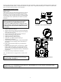
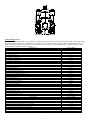
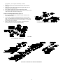
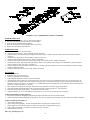
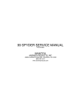
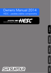
TABLE OF CONTENTS
Consumer Safety & Warranty Information
Installation Instructions . . . . .
Spare Parts List . . . . . . .
Exploded View . . . . . . .
Maintenance & Disassembly. . . .
Inspection. . . . . . . . .
Re-assemble . . . . . . .
Inner Fork Leg, Crown. & Brake Arch .
Adjusting the Ride Qualities. . . .
Trouble Shooting. . . . . . .
.
.
.
.
.
.
.
.
.
. .
.
.
.
.
.
.
.
.
.
.
.
.
.
.
.
.
.
.
.
.
.
.
.
.
.
.
.
.
.
1
2
3
4
6
8
8
9
10
11
ANSWER PRECISION SUSPENSION
CONGRATULATIONS FOR CHOOSING THE LATEST STATE OF THE ART MOUNTAIN BIKE SUSPENSION FORK
AVAILABLE. THE 2000 SX FORK MODELS HAVE STATE OF THE ART MCU/SPRING COMPRESSION SYSTEMS. THE SX
SERIES ALL USE THE NEW TWIN PISTON CARTRIDGE SYSTEM (TPC) THAT SURPASS ALL OTHER TYPES OF OIL
DAMPED SYSTEM IN PERFORMANCE AND DURABILITY.
Your 2000 SX Fork is fully assembled and ready to be installed onto your bicycle and comes equipped with a 1 1/8” threadless steer tube.
2000 SX’s are available with the V-Brake cable hangerless arch and have an optional attachable cable hanger kit P/N 85-3800, which is
available through your dealer.
CONSUMER SAFETY INFORMATION
GENERAL WARNING: Bicycling is a hazardous activity that requires that the rider stay in control of his or her bicycle at all times.
Reading this manual entirely and properly maintaining your bicycle and suspension fork and rear shock will reduce the possibility of
injury or possible death. Prior to riding your bicycle, you should inspect your suspension fork and shock to ensure that no damage
has occurred during the course of riding. Do not ride your bicycle if the fork or shock shows any signs of bending, cracking, leaking,
or if it is missing any of the originally supplied components. Any fall from your bicycle can result in serious injury or even death.
Following these instruction can help you reduce the risk of being injured.
If you are a moderate or aggressive off-road rider, or ride at least three times a week over rough terrain, Answer recommends
returning your suspension fork or shock every 2 years for a though inspection and update. Take your fork to a Manitou authorized
dealer who can arrange for shipment to Answer Products, or you may call Answer to have your fork shipped directly at (661) 2574411.
IMPORTANT: The 2000 SX Fork is a off road fork and as such, does come with the reflectors for on road use installed. Reflector
bracket kit P/N 85-3674 is available through your dealer. Have your dealer or mechanic install the kit to meet the Consumer Product
Safety Commission's (C.P.S.C.) Requirements for Bicycles if the fork is going to be used on public roads at any time. If you have
questions regarding C.P.S.C. Standards contact your dealer.
1.
2.
3.
4.
5.
Never remove or have the steer tube or stanchions (inner legs) removed from the crown. The steer tube and stanchions are press fit
assembled at the factory. Pressing them out will permanently damage the crown, steer tube, and stanchions beyond repair and render
them unsafe for any continued use.
Never attempt to thread a threadless steer tube. Machining threads will weaken the steer tube and cause unsafe condition. The only safe
thing to do is obtain the proper crown/steerer from your dealer.
Any other alterations or modifications to your fork should be considered unsafe. Contact Answer products Technical Support prior to
modifying your fork in any way for safety information.
Do not use any Manitou Fork if any part appears to be broken, bent, cracked, or damaged. Contact your dealer or Answer Products
Technical Support, (800) 670-7446, if you have any questions concerning the integrity, condition, or safe operation of your fork.
Answer Products recommends that you periodically inspect your fork for wear and damage. Inspect the Crown, Inner Legs, and Outer
Leg Dropout and Brake Arch areas for cracks or damage. Before every ride check to ensure that the proper preload exists and that the
positive rebound stop is in order to ensure that the fork can not over extend.
WARRANTY INFORMATION
Any Answer Products fork found by the factory to be defective in materials and/or workmanship within one year from the date of purchase
will be repaired or replaced at the option of the manufacturer, free of charge, when received at the factory, freight prepaid. This warranty does
not cover breakage, bending, or damage that may result from crashes or falls. This warranty does not cover any fork that has been modified,
subject to misuse or whose serial number has been altered, defaced or removed. This warranty does not cover paint damage. Any
modifications made by the user will render the warranty null and void. This warranty is expressly in lieu of all other warranties, and any
implied are limited in duration to the same duration as the expressed warranty herein. Answer Products shall not be liable for any incidental or
consequential damages.
1
If for any reason warranty work is necessary, return the fork to the place of purchase. In the USA, dealers should call Answer Products for a
return authorization number (RA#). At that time instructions for repair, return, or replacement shall be given. Customers in countries other
than USA should contact their dealer or local distributor.
INSTALLATION INSTRUCTIONS
Figures 1,2, &3
Insure that the proper steer tube has been delivered on your fork.
The steer tube may need to be cut to length to fit your bicycle
head tube. If you are not familiar with this procedure or do not
have the proper tools to cut the steer tube it is recommended that
you seek a dealer with a qualified bicycle mechanic to perform
installation.
WARNING: The steer tube and stanchions (inner legs) are a
one time precision press fit at the factory and cannot be
removed from the crown. Replacement of the entire
crown/steerer assembly must be done to change steer tube
lengths or diameters. Removing and replacing the steer tube
or stanchions will result in an unsafe condition and should
never be done.
FIGURE 1: RACE INSTALLATION
1.
2.
3.
Remove old forks from bicycle.
Measure and cut the steer tube to fit your bicycle head tube.
Remove crown race from old forks and press onto 2000 SX
Steer until seated on crown.
4. Clean and grease headset bearing and races of bicycle.
5. Install lower bearings on fork crown race.
6. Install steer tube into head tube frame.
7. Install upper bearing, spacers, and stem.
8. Install stem cap, adjust and tighten headset per
manufacturer’s instructions.
9. Install handlebars to desired height. Torque stem handlebar
pinch screw and stem clamping system to manufacturer’s
instructions.
10. Install cantilever breaks and adjust to pre manufacturers
instructions.
11. Adjust fork wheel quick release to clear the 0.275” (7MM)
thick secondary catch dropout. The quick release must be
tightened after it is adequate thread engagement (4 or more
threads with the release adjusted to bicycle per manufacturers
specifications.
12. Install brake cable per manufacturers instructions.
Note: All 2000 SX Forks are equipped with a secondary catch
dropout.
Note: The 2000 SX comes equipped with a hangerless arch.
Brake cable hangers that attach to the arch are available
through your dealer. See Figure 2
FIGURE 2: BRAKE CABLE ROUTING
WARNING: When installing wheel or any new tire check the minimum tire clearance. Measure from the highest point on the tire to
the bottom of the crown. The minimum clearance allowed is 3.268”(83.0MM) travel. Any less clearance can result in accident
resulting in serious injury or death. Figure 3
2
FIGURE 3: TIRE CLEARANCE
SPARE PARTS: Table 1
Spare parts can be ordered through your local dealer. If you have any problems that you cannot resolve with your dealer, you may call Answer
Products Technical / Warranty Service Department at (805) 257-4411, 8:00 AM to 5:00 PM, Pacific Standard, Monday through Friday. In
addition helpful information can be found on the Answer Products Web Site, http://www.answerproducts.com. Include on the site is down
loadable manuals and e-mail to technical support.
DESCRIPTION
PART NUMBER
85-3788
85-3789
85-3790
85-3791
85-3792
85-3793
85-3794
85-3795
85-3796
85-3797
85-3720
85-3720
85-3800
85-3801
85-3810
85-3812
85-3814
85-3820
85-3822
85-3827
85-3911
85-4084
85-4085
85-4086
85-4087
85-4088
85-4089
85-8989
85-9073
85-9104
85-9105
85-9108
85-9109
PART NUMBER
85-9110
85-9111
85-9112
85-9113
85-9118
85-9119
85-9120
85-9121
85-9122
85-9127
SX CROWN, 1X6.5 CM
SX CROWN, 1X7.5 CM
SX CROWN, 1X5.5 CM
SX CROWN, 1X8.5 CM
SX CROWN, 1X10.5 CM
SX CROWN, 1X12.5 CM
SX CROWN, 1 1/8”X5.5 CM
SX CROWN, 1 1/8”X6.5 CM
SX CROWN, 1 1/8”X7.5 CM
SX CROWN, 1 1/8”X8.5 CM
SX CROWN, 1 1/8”X10.5 CM
SX CROWN, 1 1/8”X12 THRDLS CM
SX CROWN, 1 1/8”X12 ALLOY
SX BRAKE HANGER KIT
MANITOU PREP M GREASE, 6 OZ.
MICRO LUBE GREASE GUN HEAD
MRD SUSPENSION FULID, 5WT., 8OZ.
MAXIMA 7.5WT SUSPENSION FLUID, 8 OZ.
MAXIMA 10WT SUSPENSION FLUID, 8OZ.
SX BUSHING SEAL KIT
2000 BUSHING SIZE TOOL
2000 SX LT FIREBALL STICKER KIT
2000 SX LT BLACK STICKER KIT
2000 SX RED STICKER KIT
2000 SX BLUE STICKER KIT
2000 SX R BLACK STICKER KIT
2000 SX R YELLOW STICKER KIT
2000 LOC-OUT KIT SX AND SX R
2000 ADJUSTER KIT SX, X-VERT
2000 ADJUSTER KIT SX LT
2000 ADJUSTER KIT SX
2000 SX LT LOWER SHAFT ASSY
2000 SX LT UPPER SHAFT ASSY
DESCRIPTION
2000 SX LOWER SHAFT ASSEMBLY
2000 SX UPPER SHAFT ASSEMBLY
2000 SX R LOWER SHAFT ASSEMBLY
2000 SX R UPPER SHAFT ASSEMBLY
2000 FIREBALL SX OUTER ASSEMBLY W/O STICKERS
2000 BLACK SX OUTER ASSEMBLY W/O STICKERS
2000 BLUE SX OUTER ASSEMBLY W/O STICKERS
2000 RED SX OUTER ASSEMBLY W/O STICKERS
2000 YELLOW SX OUTER ASSEMBLY W/O STICKERS
2000 SX SOFT RIDE KIT
3
2000 SX STOCK RIDE KIT
2000 SX FIRM RIDE KIT
2000 SX LT STEER/LEG KIT
2000 SX STEER/LEG KIT
2000 SX R STEER LEG/KIT
2000 COBALT SX OUTER ASSEMBLY W/O STICKERS
2000 WHITE SX OUTER ASSEMBLY W/O STICKERS
2000 GREEN SX OUTER ASSEMBLY W/O STICKERS
2000 COBALT SX R OUTER ASSEMBLY W/O STICKERS
2000 TREK COBALT SX STICKER KIT
2000 COMMENCAL WHITE SX STICKER KIT
2000 DECATHALON WHITE SX STICKER KIT
2000 SPECIALIZED BLACK SX STICKER KIT
2000 MERIDA COBALT SX LT STICKER KIT
2000 GIANT USA YELLOW SX STICKER KIT
2000 SCOTT SX LT KAW. GREEN STICKER KIT
2000 SPECIALIZED FIREBALL SX R STICKER KIT
2000 SPECIALIZED RED SX R STICKER KIT
2000 SPECIALIZED RED SX LT W/ALLOY STICKER KIT
85-9128
85-9129
85-9131
85-9132
85-9133
85-9134
85-9138
85-9139
85-9145
85-9148
85-9159
85-9160
85-9161
85-9163
85-9164
85-9165
85-9168
85-9169
85-9171
4
5
6
MAINTENANCE
7
IMPORTANT: The 2000 SX should not be used if any parts appear to be or are damaged. Contact your local dealer or Answer
Products for replacement parts.
IMPORTANT: Use of fork boots is required to keep your 2000 SX performing well and your warranty in effect. Use of this fork
with the boots removed will shorten the life of the fork, reduce the performance and void the warranty.
Your 2000 SX Fork requires periodic maintenance, cleaning, and inspection. Moisture and contamination may build up inside the fork
depending on the severity of riding conditions. To maintain top performance it is recommended that the fork be periodically disassembled,
cleaned, dried and re-greased.
IMPORTANT: When filling the fork with grease through the grease ports it is important to note the grease is being forced between
the upper and lower bushing. If the area is overfilled the force of the grease may force the upper bushing and dust seal out.
IMPORTANT: Before every ride you should:
1. Ensure that quick release skewers are properly adjusted and tight.
2. Wipe the inner legs clean, lubricate and check entire fork for any
obvious damage.
3. Check headset adjustment.
4. Insure that the front brake cable is properly seated in the cable
retainer & check brake adjustment.
FIGURE 7: LUBRICATING THE BUSHINGS
IMPORTANT: Maintaining the proper oil level in your TPC is very important. Not enough oil will allow foaming and reduce the
performance. Too much oil will restrict travel and may cause damage to the system and an unsafe riding situation. Finish reading
this entire section prior to making any changes to the oil level.
To check the oil level remove only the compression assembly located in the top of
he left leg. Leave the left side compression stack (adjuster, MCU, spring
ssembly) in place to keep the fork fully extended. Use a tape measure or “dip
tick” to determine the oil level. Oil level should be between 3.50” (88.6mm) and
.75” (120.6mm) below the top of the crown where the damping assembly screws
n. For all SX models with Lok-out the oil level should be between 3.75” (95mm)
nd 4.25” (1.08mm). The recommended starting oil level is 4.00” (101mm). Use
SAE 5WT for oil. (See Figure 10.)
GENERAL DISASSEMBLY
NOTE: The Fork does not need to be removed from the bicycle for general
disassembly-assembly or cleaning. It is also not necessary to disassemble
he 2000 Manitou Forks for compression Elastomer replacement.
Elastomer replacement is accomplished by removing the adjuster assembly
per Figure 12.
FIGURE 8: TPC OIL LEVEL
2. Pull outer leg assembly down to remove from the
Removal of outer leg / arch assembly Figure 9:
inner legs and crown.
. Use a 4MM allen wrench to remove the M5 lower compression rod
3. Remove fork boots.
screw from the left leg dropout. Pop out the damping adjuster knob from the 4. Bushing replacement will require the use of the
right dropout, SXR. A small screwdriver may be helpful. Use an 8MM Allen
bushing removal and installation tool available
wrench to remove the dropout nut. Fully compress the fork to prevent the
from Answer Products. It is recommended that
compression rod and damper shaft from turning while removing screws.
the bushings be left installed unless they
absolutely need replacement.
Note: It is not recommended to remove the dust seal
every time the fork is disassembled. The seal and
bushings may be cleaned and re-greased in place.
Compression Stack & Compression Rod Removal Figure 10:
1. Press the bottom clip off the compression rod.
2. Slide off the rebound elastomer from left leg compression rod.
3. Unscrew and remove the adjuster assembly by hand.
4. Turn fork upside down to remove the compression rod. If forks
are installed on bicycle give the rod a quick upward thrust and
catch it as it pops up above the crown.
Note: Lower Shaft disassembly is best done with
the fork removed from the bicycle. Disassembly
of the damping stack is not required unless you
want to change or replace the shim stack.
1.
Lower Shaft Disassembly Figure 11:
8
Remove the left cap compression damping
assembly from the top of the fork leg and pour
the oil out of the top of the fork and discard
2.
3.
4.
5.
appropriately. For complete disassembly continue.
Remove the plastic end cap and pull the lower shaft out of the
inner leg.
Remove the clear plastic detent sleeve and capture the 1/8” dia.
Detent ball used on SX R only.
SX R adjuster needle may be unscrewed from the shaft.
For SX R use 5MM allen wrench to remove piston seat. Keep note
of the exact order of the shims and spacers.
Compression Damping Disassembly Figure 12:
1. The compression damping assembly is almost identical to the
lower shaft assembly.
2. Unscrew the compression damping adjuster all the way until it
stops. The knob and the needle do not need to be removed. The
shaft also does not need to be removed from the cap. The threads
are bonded to prevent leaking.
3. Remove either the valve nut or the piston seat following the
instructions above for the lower shaft assembly.
FIGURE 10: COMPRESSION STACK
FIGURE
9: OUTER LEG REMOVAL
FIGURE 11: LOWER TPC SHAFT ASSEMBLY
9
FIGURE 12: TPC COMPRESSION DAMPING ASSEMLBY
DAMPER INSPECTION
1. Check the shaft for scratches, wear, or other obvious damage.
2. Check the seal gland and end cap seal grooves for damage.
4. Check shims for permanent bends or damage.
5. Check all other parts for obvious damage, replace if necessary.
6. Replace all seals that have been removed.
FORK INSPECTION
1. Check the fork boots for obvious damage.
2. Check the dust seal for tears, wear, or damage. Replace if needed.
3. Inspect the lower and upper bushing for damage to the Teflon coating. Replace using the bushing removal and replacement kits if
necessary.
4. Check all MCU & springs for obvious damage. Replace if necessary.
5. Check the preload adjuster and connectors. Replace if damaged.
6. Check the outer leg/arch assembly for nicks or deep gouges on outside and inside. Replace if damaged.
7. Check the inner leg for deep gouges and other damage. Minor wear resulting in color change is not detrimental to the gold anodized
surface. Replace if wear is excessive or damaged.
8. Check inner legs at the bottom of the crown for cracks or for flaking anodize. Replace crown steer leg assembly if cracked or if gold
anodize is beginning to flake.
9. Check the underside of the crown for cracks. Replace if cracked.
RE-ASSEMBLE
Lower Shaft Figure 11:
1. Install all o-rings and seals removed.
2. Grease all seals lightly with seal grease.
3. Apply small amount of blue Locktite to piston seat threads.
4. Assemble shim stack and spacers in exact order that they were removed. For SX R hand tighten piston seat. Be sure large blow off
washer will slide over piston spacer and compress the small spring. Clamp shaft in soft jaws or collet and line up slots in clamp ring
with hole in piston seat using 1/8” or smaller pin. Use a 5MM Allen wrench and tighten piston seat by turning Allen wrench and pin at
same time. Torque 10 IN-LB (3.5 N-m) max.
5. SX R install lower needle gently into shaft, thread until it stops then back off one turn for initial adjustment.
6. Slide shaft assembly through the plastic end cap, place detent ball in place and slide on 2nd STG Elastomer.
7. Insert into left leg and thread in end cap. Torque 30 IN-LB (3.5N-m) max.
8. Add approximately 90 CC of 5 WT Maxima or equivalent oil. Do not over fill. Check oil level, see Figure 8.
Compression Damping Assembly Figure 12:
1. Reassemble compression damping stack following the instructions above for the lower shaft assembly.
2. Install compression damping assembly into the left leg. The oil level should cover the compression valve when the assembly is installed.
Compression Rod & Boots Figure 13:
1. Clean all parts thoroughly.
2. Grease compression rod lightly. Be sure rebound Elastomer is installed onto compression rod.
3. Drop compression rod down into inner legs. Shake inner leg to get rod through inner leg plug.
4. Slide on black second stage, cup washer, and orange 3rd stage Elastomer.
5. Slide Boots onto inner leg.
Outer Leg Assembly Figure 14:
10
1.
2.
3.
4.
5.
6.
7.
Slide Outer leg / Arch assembly onto inner legs and fully
compress.
Install and torque 5MM compression rod screw and
dropout nut to10-30 inch-lb. (1.1-3.5 N-m). Over
torquing the dropout nut may damage the damper
shaft.
Pop in damper adjuster knob. O-ring holds knob in
place(SXR).
Slide skirt of fork boots onto the outer leg groove. Be sure
the lip snaps into the groove.
Clean adjuster cap threads thoroughly. Clean threads on
inside of inner leg.
Assemble MCU’s, springs, and connectors with thick
grease.
Install adjuster assembly into inner leg just hand tight.
FIGURE 13: COMPRESSION ROD & BOOT
INNER FORK LEGS & CROWN
The inner fork legs and steer tube are press fit into the
crown and may never be removed. Removing them will
make the fork unsafe to use. If you see any slippage
contact Answer Technical Staff immediately (800) 6707446.
FIGURE 14: OUTER LEG ASSEMBLY
ADJUSTING RIDE QUALITIES
2000 SX TPC forks offer a wide adjustment range to suit individual riding preference and rider weight by simply changing the MicroCellular
Urethane (MCU’s). Fine tune adjustments can be made using the preload adjusters located on top of the fork crown. Softer blue and harder
yellow MCU’s are available from your Dealer.
NOTE: Since 2000 model forks use a compression stack in the left leg only, MCU’s and Springs used in previous Manitou forks are NOT
interchangeable with later versions of SX model Forks.
Compression Spring Fine Tuning: Figure 15
Fine tuning adjustments to the spring rate are made by rotating the adjuster knobs located on
top of the crown. Note the 2000 SX LT, SX, and SX R uses compression spring systems in
the left leg only. Only the left knob on top of the crown adjusts preload. Rotating the knob
11
clockwise will firm the ride, adding preload
to the compression stack. Rotating the
knob counter clockwise will soften the ride.
Four full revolutions will take the adjuster from full soft to the extreme firm setting.
Compression Damping Fine Tuning: Figure 16
To adjust the SX R simply rotate the compression damping knob located on top of the right leg
and crown. Rotating the knob clockwise will increase the damping, rotating the knob counter
clockwise will reduce the damping. Excessive damping will give you a harsh ride over sharp
bumps like rocky sections, but will feel good in large hits like G-outs. Insufficient
compression damping will bottom out in the large hit G-outs and bob a little while climbing but
feel plush on the sharp hits. A correctly adjusted fork will perform good in all conditions. The
SX LT and SX uses TPC Sport for compression damping and is not adjustable.
Rebound Damping Fine Tuning: Figure 17
To adjust the SX R simply rotate the rebound damping knob located on bottom of the right leg.
Rotating the knob clockwise will increase the damping, rotating the knob counter clockwise
will reduce the damping. Excessive rebound damping will give you a harsh ride over repetitive
bumps (like braking bumps) because the fork will pack up. Insufficient rebound damping will
make the fork over active, top out and slap back when landing from a jump. We suggest that
you try adjusting your fork on the very active side, minimum rebound. Then try it over a
variety of terrain and tune in more rebound from there. The SX LT and SX uses TPC Sport for
Rebound damping and is not adjustable
Lok-Out System Kit P/N 85-8989
Lok-Outs are available for all SX models. By turning the knob _ turn CCW, exposing the green
sticker; the front fork will have regular TPC suspension. By turning the knob _ turn CW,
exposing the red sticker; the fork will be locked out. A safety blow off valve will open under
extreme conditions to allow some movement. To adjust the compression damping when not
using the Lok-Out. Remove the compression damping assembly from the top of the right leg.
Adjust the setscrew, located in the valve seat, in to increase the damping and out to reduce the
compression damping. Try adjusting one _ turn at a time.
FIGURE 15: PRELOAD
FIGURE 16: COMPRESSION DAMPING
For additional tuning tips we recommend that you obtain a copy of the MRD tuning
Manual P/N 85-3485 and check out the MRD Race Tuning kits available at your dealer.
FIGURE 17: REBOUND DAMPING
TROUBLE SHOOTING
Fork seems to "top out" or has a slight clunking feel when front wheel comes off the ground:
Excessive preload or insufficient rebound damping will result in a "top out" . Select MCU’s that better fit your weight and riding style, having
the preload adjuster set mid to low range, and increase the rebound damping to eliminate "top out".
The fork feels less active and is not getting the travel it used to when it was new:
Chances are that the fork is developing stiction. Cleaning and applying light oil to the stanchions will help.
Outer legs feel loose on inner legs and bushings, a knock or rock can be felt when pushed from side to side:
A very small knock is normal with the new harder bushings. If the knock is excessive or you can feel the fork rocking then the bushings
should be removed and replaced. To do this you must have the Answer Products Bushing Removal and Replacement Tool Kit.
A small amount of oil seems to be leaking from top of the left leg at the adjuster cap:
If the 2000 SX us store upside down for a period of time a small amount of oil may leak through the adjuster cap / knob assembly. The cap
area is not subjected to damping pressure. A small leak in that area will not affect the performance of the fork or cause any type of damage.
12
We recommend that you store your Manitou left side up. If this condition causes you some problems please contact your Answer Products
dealer or call our warranty tech department for prompt service.
CYCLE COMPUTER INSTALLATION INSTRUCTIONS:
Follow the instructions in your owners manual with the following exceptions:
WARNING: DO NOT DRILL A HOLE IN THE DROPOUT. THIS MAY
WEAKEN THE DROPOUT, WILL VOID THE WARRANTY, AND MAY
CAUSE AN UNSAFE CONDITION WITH RISK OF INJURY. DO NOT USE
THE TEMPLATE PROVIDED IN THE 95 OR 96 SERVICE MANUAL.
2000 SX SERVICE MANUAL
P/N 85-3688
ANSWER
ANSWER PRODUCTS
28209 AVENUE STANFORD, VALENCIA, CA 91355
(661) 257-4411
www.answerproducts.com
13