1
TECHNICAL MANU
AL
MANUAL
*PG13
R410A Single Phase
Package Gas Units
• Refer to Service Manual RS6300007 for installation, operation, and troubleshooting information.
• All safety information must be followed as provided in the Service Manual.
• Refer to the appropriate Parts Catalog for part number information.
• Models listed on page 3.
®
C
US
This manual is to be used by qualified, professionally trained HVAC
technicians only. Goodman does not assume any responsibility for
property damage or personal injury due to improper service procedures
or services performed by an unqualified person.
Copyright © 2009-2010 Goodman Manufacturing Company, L.P.
RT6312004r1
March 2010
PRODUCT IDENTIFICATION
The model number is used for positive identification of component parts used in manufacturing. Please use this number
when requesting service or parts information.
A or G
P G 13 24 045 M 4 1
A
A
Minor Revision
A: Initial Revision
Product Brand
A: Amana® Brand
G: Goodman® Brand
Major Revision
A: Initial Revision
Product Type
Voltage
Single Package
Cooling/Heating
1: 208/230V/60Hz/1ph
Product Family
Refrigerant
G - Gas/Electric
4: R410A
Product Series
Configuration
13: Up to 13 SEER
M: Multi-position
WARNING
Nominal Capacity
Heating Input
24:
30:
36:
42:
48:
60:
045: 46,000
070: 69,000
090: 92,000
115: 115,000
140: 138,000
24,000 BTUH
30,000 BTUH
36,000 BTUH
42,000 BTUH
48,000 BTUH
60,000 BTUH
HIGH VOLTAGE!
Disconnect ALL power before servicing or installing this unit. Multiple power
sources may be present. Failure to do so may cause property damage, personal
injury or death.
Goodman will not be responsible
for any injury or property damage
arising from improper service or service procedures. If
you install or perform service on this unit, you assume
responsibility for any personal injury or property damage
which may result. Many jurisdictions require a license to
install or service heating and air conditioning equipment.
WARNING
2
BTUH
BTUH
BTUH
BTUH
BTUH
ONLY individuals meeting (at a
minimum) the requirements of
an "Entry Level Technician" as specified by the AirConditioning, Heating, and Refrigeration Institute (AHRI)
may use this information. Attempting to install or repair
this unit without such background may result in product
damage, personal injury, or death.
WARNING
PRODUCT IDENTIFICATION
The model number is used for positive identification of component parts used in manufacturing. Please use this number
when requesting service or parts information.
WARNING
APG1324045M41AA
APG1324070M41AA
APG1330045M41AA
APG1330070M41AA
APG1336045M41AA
APG1336070M41AA
APG1336090M41AA
APG1342070M41AA
APG1342090M41AA
APG1348070M41AA
APG1348090M41AA
APG1348115M41AA
APG1360090M41AA
APG1360115M41AA
APG1360140M41AA
GPG1324045M41AA
GPG1324070M41AA
GPG1330045M41AA
GPG1330070M41AA
GPG1336045M41AA
GPG1336070M41AA
GPG1336090M41AA
GPG1342070M41AA
GPG1342090M41AA
GPG1348070M41AA
GPG1348090M41AA
GPG1348115M41AA
GPG1360090M41AA
GPG1360115M41AA
GPG1360140M41AA
APG1324045M41AB
APG1324070M41AB
APG1330045M41AB
APG1330070M41AB
APG1336045M41AB
APG1336070M41AB
APG1336090M41AB
APG1342070M41AB
APG1342090M41AB
APG1348070M41AB
APG1348090M41AB
APG1348115M41AB
APG1360090M41AB
APG1360115M41AB
APG1360140M41AB
GPG1324045M41AB
GPG1324070M41AB
GPG1330045M41AB
GPG1330070M41AB
GPG1336045M41AB
GPG1336070M41AB
GPG1336090M41AB
GPG1342070M41AB
GPG1342090M41AB
GPG1348070M41AB
GPG1348090M41AB
GPG1348115M41AB
GPG1360090M41AB
GPG1360115M41AB
GPG1360140M41AB
The United States Environmental Protection Agency (“EPA”) has issued various regulations regarding the introduction and disposal of refrigerants introduced into this unit. Failure to follow
these regulations may harm the environment and can lead to the imposition of substantial fines.
These regulations may vary by jurisdiction. Should questions arise, contact your local EPA office.
Do not connect or use any device
that is not design certified by
Goodman for use with this unit.
Serious property damage, personal injury, reduced unit
performance and/or hazardous conditions may result
from the use of such non-approved devices.
WARNING
To prevent the risk of property
damage, personal injury, or death,
do not store combustible materials or use gasoline or
other flammable liquids or vapors in the vicinity of this
appliance.
WARNING
3
PRODUCT DESIGN
*PG13 Package Gas Units are designed for outdoor installations only in either residential or light commercial applications and are available in 2 through 5 ton sizes. They are
designed for 208/230 volt single phase applications. (*PG13
3, 4 and 5 ton models are also available for 230V 3 phase
applications. See Technical Manual RT6312005*.)
-
Due to their design Scroll compressors are inherently more
tolerant of liquid refrigerant. NOTE: Even though the compressor section of a Scroll compressor is more tolerant
of liquid refrigerant, continued floodback or flooded start
conditions may wash oil from the bearing surfaces causing premature bearing failure.
The connecting ductwork (Supply and Return) can be connected for either horizontal or vertical airflow. In the vertical
application, a matching Roof Curb is recommended.
-
These Scroll compressors use white oil which is compatible with 3GS. 3GS oil may be used if additional oil is
required.
A return air filter must be installed behind the return air grille(s)
or provision must be made for a filter in an accessible location within the return air duct. The minimum filter area should
not be less than those sizes listed in the Specification Section. Under no circumstances should the unit be operated
without return air filters.
-
Compliant scroll compressors perform "quiet" shutdowns
that allow the compressor to restart immediately without
the need for a time delay. This compressor will restart
even if the system has not equalized.
-
Operating pressures and amp draws may differ from standard reciprocating compressors. This information may be
found in the "Cooling Performance Data" section.
A 3/4" pipe is provided for removal of condensate water from
the indoor coil. (Do not reduce the drain line size).
NOTE: Tighten drain to a maximum torque of 10 in-lbs
Refrigerant flow control is achieved by use of restrictor orifices. *PG13 units use the FasTest Access Fitting System
which consists of a saddle that is either soldered to the suction and liquid lines or is fastened with a locking nut to the
access fitting box (core) and then screwed into the saddle.
NOTE: The core must not be removed from the saddle
until the refrigerant charge has been removed. Failure
to do so could result in property damage or personal
injury.
Location and Clearances
NOTE: To ensure proper condensate drainage, unit must be
installed in a level position.
The single phase units use permanent split capacitors (PSC)
design compressors. Starting components are therefore not
required. A low MFD run capacitor assists the compressor
to start and remains in the circuit during operation.
The outdoor fan and indoor blower motors are single phase
permanent split capacitor type motors. *PG1348***M41** and
*PG1360***M41** models are equipped with X-13 indoor
blower motors. X-13 motors are constant torque motors with
very low power consumption and are energized by a 24V
signal from the ignition control. The X-13 features an integrated control module.
Air for condensing (cooling cycle)is drawn through the outdoor coil by a propeller fan, and is discharged vertically out
the top of the unit. The outdoor coil is designed for .0 static.
No additional restriction (ductwork) shall be applied.
Conditioned air is drawn through the filter(s), field installed,
across the coil and back into the conditioned space by the
indoor blower.
Some models of the *PG13 series package units use the
Compliant Scroll compressor, there are a number of design
characteristics which are different from the traditional reciprocating compressor.
4
48" MIN
12" MIN
36" MIN
(FOR
SERVICE)
.
3"
MIN
12" MIN
36" MIN
(FOR SERVICE)
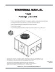
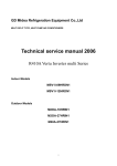
Outside Slab Installation
NOTE: Roof overhang should be no more than 36" and provision made to deflect the warm discharge air out from the
overhand. Minimum clearances are required to avoid air recirculation and keep the unit operating at peak efficiency.
PRODUCT DESIGN
WARNING
TO PREVENT POSSIBLE PROPERTY DAMAGE, THE
UNIT SHOULD REMAIN IN AN UPRIGHT POSITION
DURING ALL RIGGING AND MOVING OPERATIONS.
TO FACILITATE LIFTING AND MOVING IF A CRANE IS
USED, PLACE THE UNIT IN AN ADEQUATE CABLE
SLING.
IMPORTANT: If using bottom discharge with roof curb,
ductwork should be attached to the curb prior to installing
the unit.
Refer to Roof Curb Installation Instructions for proper curb
installation. Curbing must be installed in compliance with
the National Roofing Contractors Association Manual.
Rooftop Installation
NOTE: To ensure proper condensate drainage, unit must be
installed in a level position.
5
PRODUCT DESIGN
High Altitude Derate - U.S. Installations Only (Optional)
High Altitude Derate is not required for proper operation. The
gas/electric units naturally derate with altitude. High Altitude
Derate kit may be installed if desired.
IMPORTANT NOTE: The gas/electric units naturally derate
with altitude. Do not attempt to increase the firing rate by
changing orifices or increasing the manifold pressure. This
can cause poor combustion and equipment failure. At all
altitudes, the manifold pressure must be within 0.3 inches
W.C. of that listed on the nameplate for the fuel used. At all
altitudes and with either fuel, the air temperature rise must
be within the range listed on the unit nameplate. Refer to the
Installation Manual provided with the LP kit for conversion
from natural gas to propane gas and for altitude adjustments.
When this package unit is installed at high altitude, the appropriate High Altitude orifice kit may be installed. As altitude increases, there is a natural reduction in the density of
both the gas fuel and combustion air. This kit will provide the
proper design certified input rate within the specified altitude
range. High altitude kits are not approved for use in Canada.
For installations above 2,000 feet, use kit HA-02. The HA-02
kit is used for both Natural and LP gas at high altitudes.
Use *LPT-03 propane conversion kit for propane conversions
at altitudes below 2000 feet. Natural gas installations below
2000 feet do not require a kit.
For propane conversion above 2000 feet, high altitude kit
HA-02 is required in addition to the *LPT-03 propane conversion kit.
*LPT-00A may be used on models with AA revisions.
NATURAL GAS AND LP GAS INSTALLATIONS AT ALTITUDES > 2000 FT
INPUT/BURNER
20,000 BTUH NAT/20,000 BTUH/L.P.
HIGH ALTITUDE
KIT
ELEVATION ABOVE SEA-LEVEL (FEET)
2000 3000 4000 4500 5000 6000 7000 8000
U.S. BURNER ORIFICE
CANADA BURNER ORIFICE
INPUT/BURNER
HA-02
45/55 47/55 47/56
45/55
-
-
48/57
47/56 48/57 48/58 49/58
-
-
-
-
22,500 BTUH NAT/20,000 BTUH/L.P.
HIGH ALTITUDE
KIT
ELEVATION ABOVE SEA-LEVEL (FEET)
2000 3000 4000 4500 5000 6000 7000 8000
U.S. BURNER ORIFICE
CANADA BURNER ORIFICE
INPUT/BURNER
HA-02
44/55 44/55 45/56
44/55
-
-
47/57
45/56 46/57 47/58 47/58
-
-
-
-
25,000 BTUH NAT/20,000 BTUH/L.P.
HIGH ALTITUDE
KIT
ELEVATION ABOVE SEA-LEVEL (FEET)
2000 3000 4000 4500 5000 6000 7000 8000
U.S. BURNER ORIFICE
CANADA BURNER ORIFICE
6
HA-02
43/55 43/55 44/56
43/55
-
-
46/57
44/56 44/56 45/57 45/57
-
-
-
-
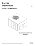
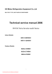
PACKAGE GAS SPECIFICATIONS
UNIT DIMENSIONS
47
51
FLUE EXHAUST
HOOD
18 7/16
16
FLUE EXHAUST
1 3/8
C
A
5 1/2
16
7 15/16
B
SUCTION/LIQUID PRESSURE PORTS
BEHIND COMPRESSOR ACCESS PANEL
2 3/4
COMBUSTION AIR INTAKE
RETURN
B
HEAT EXCHANGE ACCESS PANEL
4 3/4
GAS SUPPLY ENTRANCE
CONDENSATE DRAIN CONNECTION
3/4" NPT FEMALE
SUPPLY
3
EVAPORATOR/CONTROL PANEL ACCESS PANEL
16 1/8
19 1/8
OF
R
T E IT Y
N
V
C E RA
G
7 5/16
7 7/8
20
24
DIMENSION
(INCHES)
MEDIUM
LARGE
A
B
C
32
16
9 1/2
40
18
14
POWER WIRE ENTRANCE
CONTROL WIRE ENTRANCE
5 1/4
EXHAUST FLUE HOOD
BLOWER ACCESS PANEL
COMBUSTION
AIR INTAKE
11
5 3/4
22
MEDIUM CHASSIS
22
*PG1324, 30, 36
LARGE CHASSIS
11
*PG1342, 48, 60
SUPPLY
RETURN
7
PRODUCT DIMENSIONS
*PG13[24-36]***M41A*
*PG1324045M4
AA/AB
COOLING
COOLING CAPACITY, BTUH
CAPACITY
SEER / EER
HEATING INPUT BTUH
(U.S. & CANADIAN)
HEATING
HEATING OUTPUT BTUH (U.S. & CANADIAN)
CAPACITY
AFUE (%)
*PG1324070M41
AA/AB
*PG1330045M4
AA/AB
*PG1330070M41
AA/AB
*PG1336045M41
AA/AB
23,600
23,600
28,600
28,600
36,000
13.0 / 11.0
13.0 / 11.0
13.0 / 11.0
13.0 / 11.0
13.0 / 10.75
46,000
69,000
46,000
69,000
46,000
36,700
55,000
36,700
55,000
36,700
80
80
80
80
80
TEMPERATURE RISE (°F)
30 - 60
35 - 65
30 - 60
35 - 65
30 - 60
UNIT
VOLTAGE (NAMEPLATE)
208/230
208/230
208/230
208/230
208/230
ELECTRICAL
UNIT AMPS (TOTAL)
11.3
11.3
13.9
13.9
21.2
13.4
13.4
16.6
16.6
25.4
MAXIMUM OVERCURRENT PROTECTION
20
20
25
25
40
HEATING
NUMBER OF BURNERS
2
3
2
3
2
SECTION
ORIFICE SIZE NATURAL
43
43
43
43
43
SPECIFICATION MINIMUM CIRCUIT AMPACITY
(3)
ORIFICE SIZE LP
COMPRESSOR TYPE
55
55
55
55
55
Recip
Recip
Recip
Recip
Scroll
RATED LOAD AMPS
8.3
8.3
10.6
10.6
16.7
LOCKED ROTOR AMPS
43.0
43.0
54.0
54.0
79.0
CONDENSER
HORSEPOWER
1/4
1/4
1/4
1/4
1/4
FAN MOTOR
RPM
830
830
1100
1100
830
FULL LOAD AMPS
1.5
1.5
1.4
1.4
1.5
LOCKED ROTOR AMPS
3.0
3.0
2.9
2.9
3.0
BLADE DIAMETER (INCHES)
22
22
22
22
22
3
3
3
3
3
CFM
2400
2400
2700
2700
2400
CONDENSER
FACE AREA - SQ. FT.
12.3
12.3
12.3
12.3
12.3
COIL
NUMBER OF ROWS
1
1
1
1
1
FINS PER INCH
24
24
24
24
24
1/3 - 3
CONDENSER
FAN
NUMBER OF BLADES
EVAPORATOR
HORSEPOWER - NO. OF SPEEDS
1/4 - 3
1/4 - 3
1/3 - 3
1/3 - 3
BLOWER
FULL LOAD AMPS
1.5
1.5
1.9
1.9
3.1
MOTOR
LOCKED ROTOR AMPS
2.2
2.2
3.1
3.1
4.1
MOTOR SPEED TAP - COOLING
Med
Med
Med
Med
High
RPM
952
952
1,015
1,015
910
10” x 8”
10” x 8”
10” x 8”
10” x 8”
10” x 9”
1200
EVAPORATOR
DIAMETER X WIDTH (INCHES)
BLOWER
RATED SCFM COOLING
800
800
1000
1000
MAX EXTERNAL STATIC PRESS ("w.c.)
0.5
0.5
0.5
0.5
0.5
EVAPORATOR
FACE AREA - SQ. FT.
4.33
4.33
4.33
4.33
4.33
COIL
NUMBER OF ROWS
3
3
4
4
4
FINS PER INCH
16
16
16
16
14
4.2
(2)
2.7
2.7
3.3
3.3
DRAIN SIZE (INCHES)
3/4
3/4
3/4
3/4
3/4
HEATING
PRIMARY LIMIT SETTING (°F)
150
150
150
150
150
LIMITS
AUXILIARY LIMIT SETTING (°F)
150
150
150
150
150
ROLLOUT LIMIT SETTING (°F)
350*
350*
350*
350*
350*
GENERAL
PISTON EXPANSION DEVICE
Orifice (.053)
Orifice (.053)
Orifice (.062)
Orifice (.062)
Orifice (.070)
INFORMATION
REFRIGERANT CHARGE R-410A (Oz.)
80
80
80
80
85
1 1/8
1 1/8
1 1/8
1 1/8
1 1/8
FILTER SIZE - SQ. FT.
POWER SUPPLY ENTRANCE SIZE (INCHES)
LOW VOLTAGE ENTRANCE SIZE (INCHES)
7/8
7/8
7/8
7/8
7/8
SHIPPING WEIGHT LBS.
435
439
438
442
470
OPERATING WEIGHT LBS.
412
417
415
420
449
(1) Units installed in Canada are certifed only to 4500 feet.
(2) Calculated external filter size based on air velocity of 300 ft/min. and applies to disposable filters only.
(3) Maximum Overcurrent Protection Device: MUST use Time Delay Fuse or HACR type Circuit Breaker of the same size as noted.
IMPORTANT: While this data is presented as a guide, it is important to electrically connect the unit and properly size wires and fuses/circuit
breakers in accordance with the National Electrical Code and/or all local codes.
*
AA revision models rollout limit setting is 300°. AB revision rollout limit setting is 350°.
8
PACKAGE GAS SPECIFICATIONS
*PG1336070M41
AA/AB
COOLING
COOLING CAPACITY, BTUH
CAPACITY
SEER / EER
*PG13[36-48]***M41A*
*PG1336090M41
AA/AB
*PG1342070M41
AA/AB
*PG1342090M41
AA/AB
*PG1348070M41
AA/AB
36,000
36,000
40,500
40,500
46,000
13.0 / 10.75
13.0 / 10.75
13.0 / 11.0
13.0 / 11.0
13.0 / 11.0
69,000
92,000
69,000
92,000
69,000
55,000
73,600
55,000
73,600
55,000
80
80
80
80
80
TEMPERATURE RISE (°F)
35 - 65
45 - 75
35 - 65
45 - 75
35 - 65
UNIT
VOLTAGE (NAMEPLATE)
208/230
208/230
208/230
208/230
208/230
ELECTRICAL
UNIT AMPS (TOTAL)
21.2
21.2
22.3
22.3
27.1
25.4
25.4
26.8
26.8
32.1
50
HEATING INPUT BTUH
(U.S. & CANADIAN)
HEATING
HEATING OUTPUT BTUH (U.S. & CANADIAN)
CAPACITY
AFUE (%)
SPECIFICATION MINIMUM CIRCUIT AMPACITY
MAXIMUM OVERCURRENT PROTECTION
40
40
40
40
HEATING
NUMBER OF BURNERS
3
4
3
4
3
SECTION
ORIFICE SIZE NATURAL
43
43
43
43
43
ORIFICE SIZE LP
55
55
55
55
55
Scroll
Scroll
Scroll
Scroll
Scroll
RATED LOAD AMPS
16.7
16.7
17.9
17.9
19.9
LOCKED ROTOR AMPS
79.0
79.0
112.0
112.0
109.0
COMPRESSOR TYPE
CONDENSER
HORSEPOWER
1/4
1/4
1/4
1/4
1/4
FAN MOTOR
RPM
830
830
1100
1100
1100
FULL LOAD AMPS
1.5
1.5
1.4
1.4
1.4
LOCKED ROTOR AMPS
3.0
3.0
2.9
2.9
2.9
BLADE DIAMETER (INCHES)
22
22
22
22
22
3
3
3
3
3
CFM
2400
2400
3500
3500
3500
CONDENSER
FACE AREA - SQ. FT.
12.3
12.3
15.4
15.4
15.4
COIL
NUMBER OF ROWS
1
1
1
1
1
FINS PER INCH
24
24
24
24
24
EVAPORATOR HORSEPOWER - NO. OF SPEEDS
1/3 - 3
1/3 - 3
1/3 - 3
1/3 - 3
3/4 - 5
BLOWER
FULL LOAD AMPS
3.06
3.06
3.06
3.06
5.8
MOTOR
LOCKED ROTOR AMPS
4.1
4.1
4.1
4.1
--
High
High
Medium
Medium
T4
CONDENSER
FAN
NUMBER OF BLADES
MOTOR SPEED TAP - COOLING
RPM
EVAPORATOR DIAMETER X WIDTH (INCHES)
BLOWER
RATED SCFM COOLING
MAX EXTERNAL STATIC PRESS ("w.c.)
EVAPORATOR FACE AREA - SQ. FT.
910
910
910
910
1050
10” x 9”
10” x 9”
10” x 10”
10” x 10”
11” x 10”
1200
1200
1300
1300
1520
0.5
0.5
0.5
0.5
0.5
4.33
4.33
5.67
5.67
5.67
NUMBER OF ROWS
4
4
4
4
4
FINS PER INCH
14
14
14
14
14
FILTER SIZE - SQ. FT. (2)
4.2
4.2
4.7
4.7
5.1
DRAIN SIZE (INCHES)
3/4
3/4
3/4
3/4
3/4
HEATING
PRIMARY LIMIT SETTING (°F)
150
150
150
150
150
LIMITS
AUXILIARY LIMIT SETTING (°F)
150
150
150
150
150
ROLLOUT LIMIT SETTING (°F)
350*
350*
350*
350*
350*
PISTON EXPANSION DEVICE
Orifice (.070)
Orifice (.070)
Orifice (.072)
Orifice (.072)
Orifice (.076)
85
85
105
105
125
1 1/8
1 1/8
1 1/8
1 1/8
1 1/8
COIL
GENERAL
INFORMATION REFRIGERANT CHARGE R-410A (Oz.)
POWER SUPPLY ENTRANCE SIZE (INCHES)
LOW VOLTAGE ENTRANCE SIZE (INCHES)
7/8
7/8
7/8
7/8
7/8
SHIPPING WEIGHT LBS.
475
480
515
520
540
OPERATING WEIGHT LBS.
453
458
493
496
518
(1) Units installed in Canada are certifed only to 4500 feet.
(2) Calculated external filter size based on air velocity of 300 ft/min. and applies to disposable filters only.
(3) Maximum Overcurrent Protection Device: MUST use Time Delay Fuse or HACR type Circuit Breaker of the same size as noted.
IMPORTANT: While this data is presented as a guide, it is important to electrically connect the unit and properly size wires and fuses/circuit
breakers in accordance with the National Electrical Code and/or all local codes.
*
AA revision models rollout limit setting is 300°. AB revision rollout limit setting is 350°.
9
PACKAGE GAS SPECIFICATIONS
*PG1348090M41
AA/AB
COOLING
COOLING CAPACITY, BTUH
CAPACITY
SEER / EER
*PG13[48-60]***M41A*
*PG1348115M41
AA/AB
*PG1360090M41
AA/AB
*PG1360115M41
AA/AB
*PG1360140M41
AA/AB
46,000
46,000
57,000
57,000
57,000
13.0 / 11.0
13.0 / 11.0
13.0 / 11.0
13.0 / 11.0
13.0 / 11.0
92,000
115,000
92,000
115,000
138,000
73,600
92,000
73,600
92,000
110,400
80
80
80
80
80
TEMPERATURE RISE (°F)
45 - 75
45-75
45 - 75
45 - 75
45 - 75
UNIT
VOLTAGE (NAMEPLATE)
208/230
208/230
208/230
208/230
208/230
ELECTRICAL
UNIT AMPS (TOTAL)
27.1
27.1
35.2
35.2
35.2
SPECIFICATION
MINIMUM CIRCUIT AMPACITY
32.1
32.1
42.0
42.0
42.0
60
HEATING INPUT BTUH
(U.S. & CANADIAN)
HEATING
HEATING OUTPUT BTUH (U.S. & CANADIAN)
CAPACITY
AFUE (%)
MAXIMUM OVERCURRENT PROTECTION
50
50
60
60
HEATING
NUMBER OF BURNERS
4
5
4
5
6
SECTION
ORIFICE SIZE NATURAL
43
43
43
43
43
ORIFICE SIZE LP
COMPRESSOR
TYPE
55
55
55
55
55
Scroll
Scroll
Scroll
Scroll
Scroll
RATED LOAD AMPS
19.9
19.9
26.4
26.4
26.4
LOCKED ROTOR AMPS
109.0
109.0
134.0
134.0
134.0
CONDENSER
HORSEPOWER
FAN MOTOR
RPM
1/4
1/4
1/4
1/4
1/4
1100
1100
1100
1100
1100
FULL LOAD AMPS
1.4
1.4
1.4
1.4
1.4
LOCKED ROTOR AMPS
2.9
2.9
2.9
2.9
2.9
BLADE DIAMETER (INCHES)
22
22
22
22
22
3
3
3
3
3
CFM
3500
3500
3250
3250
3250
CONDENSER
FACE AREA - SQ. FT.
15.4
15.4
15.4
15.4
15.4
COIL
NUMBER OF ROWS
1
1
2
2
2
FINS PER INCH
24
24
24
24
24
3/4 - 5
3/4 - 5
1 -5
1-5
1-5
5.8
5.8
7.4
7.4
7.4
CONDENSER
FAN
NUMBER OF BLADES
EVAPORATOR
HORSEPOWER - NO. OF SPEEDS
BLOWER
FULL LOAD AMPS
MOTOR
LOCKED ROTOR AMPS
--
--
--
--
--
MOTOR SPEED TAP - COOLING
T4
T4
T4
T4
T4
RPM
EVAPORATOR
DIAMETER X WIDTH (INCHES)
BLOWER
RATED SCFM COOLING
1050
1050
1050
1050
1050
11” x 10”
11” x 10”
11” x 10”
11” x 10”
11” x 10”
1750
1520
1520
1750
1750
MAX EXTERNAL STATIC PRESS ("w.c.)
0.5
0.5
0.5
0.5
0.5
EVAPORATOR
FACE AREA - SQ. FT.
5.67
5.67
5.67
5.67
5.67
COIL
NUMBER OF ROWS
4
4
4
4
4
FINS PER INCH
14
14
14
14
14
FILTER SIZE - SQ. FT. ( 2)
5.1
5.1
6.3
6.3
6.3
DRAIN SIZE (INCHES)
3/4
3/4
3/4
3/4
3/4
HEATING
PRIMARY LIMIT SETTING (°F)
150
150
150
150
150
LIMITS
AUXILIARY LIMIT SETTING (°F)
150
150
150
150
150
ROLLOUT LIMIT SETTING (°F)
350*
350*
350*
350*
350*
GENERAL
PISTON EXPANSION DEVICE
Orifice (.076)
Orifice (.076)
Orifice (.087)
Orifice (.087)
Orifice (.087)
INFORMATION
REFRIGERANT CHARGE R-410A (Oz.)
125
125
185
185
185
POWER SUPPLY ENTRANCE SIZE (INCHES)
1 1/8
1 1/8
1 1/8
1 1/8
1 1/8
LOW VOLTAGE ENTRANCE SIZE (INCHES)
7/8
7/8
7/8
7/8
7/8
SHIPPING WEIGHT LBS.
545
550
555
560
565
OPERATING WEIGHT LBS.
523
528
533
538
543
(1) Units installed in Canada are certifed only to 4500 feet.
(2) Calculated external filter size based on air velocity of 300 ft/min. and applies to disposable filters only.
(3) Maximum Overcurrent Protection Device: MUST use Time Delay Fuse or HACR type Circuit Breaker of the same size as noted.
IMPORTANT: While this data is presented as a guide, it is important to electrically connect the unit and properly size wires and fuses/circuit
breakers in accordance with the National Electrical Code and/or all local codes.
*
AA revision models rollout limit setting is 300°. AB revision rollout limit setting is 350°.
10
ACCESSORIES
ACCESSORIES
Part Number
Description
LPT-03
Propane Conversion Kit (LPT-00A may be used on models with AA revisions)
HA-02
High Altitude Kit
PGC101/102/103
Roof Curb
PGED101/102
Downflow Economizer, Small and Medium Chassis
PGED103
Downflow Economizer, Large Chassis
PGEH101/102
Horizontal Economizer, Small and Medium Chassis
PGEH103
Horizontal Economizer, Large Chassis
PGMDD101/102
Manual 25% Fresh Air Damper Downflow Application, Small and Medium Chassis
PGMDD103
Manual 25% Fresh Air Damper Downflow Application, Large Chassis
PGMDH101
Manual 25% Fresh Air Damper Horizontal Application, Small Chassis
PGMDH102
Manual 25% Fresh Air Damper Horizontal Application, Medium Chassis
PGMDH103
Manual 25% Fresh Air Damper Horizontal Application, Large Chassis
PGMDMD101/102
Motorized 25% Fresh Air Damper Downflow Application,Small and Medium Chassis
PGMDMD103
Motorized 25% Fresh Air Downflow Application, Large Chassis
PGMDMH101
Motorized 25% Fresh Air Damper Horizontal Application, Small Chassis
PGMDMH102
Motorized 25% Fresh Air Damper Horizontal Application, Medium Chassis
PGMDMH103
Motorized 25% Fresh Air Damper Horizontal Application, Large Chassis
SQRPG101/102
Square to Round Adapter w/ 16" Round Downflow Application, Small and Medium Chassis
SQRPG103
Square to Round Adapter w/ 18" Round Downflow Application, Large Chassis
SQRPGH101/102
Square to Round Adapter w/ 16" Round Horizontal Application, Small and Medium Chassis
SQRPGH103
Square to Round Adapter w/ 18" Round Horizontal Application, Large Chassis
PGFR101/102/103
Internal Filter Rack All Chassis
GPGHFR101-103
External Horizontal Filter Rack for Goodman/Amana Gas/Electric
& Multi-position Package Units All Chassis
CDK36
Flush Mount Concentric Duct Kit
CDK36515
Flush Mount Concentric Duct Kit w/ Filter
CDK36530
Step Down Concentric Duct Kit
CDK36535
Step Down Concentric Duct Kit w/ Filter
CDK4872
Flush Mount Concentric Duct Kit
CDK4872515
Flush Mount Concentric Duct Kit w/ Filter
CDK4872530
Step Down Concentric Duct Kit
CDK4872535
Step Down Concentric Duct Kit w/ Filter
11
*PG13[24-30]***M41A*
BLOWER PERFORMANCE DATA
*PG1324045M41A* - Rise Range: 30° - 60°
Unit
Static
0.1
0.2
0.3
0.4
0.5
0.6
0.7
0.8
CFM
600
570
510
450
380
----------------------
LOW
WATTS
AMPS
150
0.67
140
0.65
130
0.63
125
0.61
120
0.58
-------------------------------------------
CFM
600
570
510
450
380
----------------------
LOW
WATTS
AMPS
150
0.67
140
0.65
130
0.63
125
0.61
120
0.58
-------------------------------------------
RISE
57
60
NR
NR
NR
NR
NR
NR
CFM
850
830
765
715
660
610
---------------
MEDIUM
WATTS
AMPS
230
1.02
220
1.00
215
0.97
210
0.94
205
0.90
195
0.88
-----------------------------
RISE
40
41
45
48
52
56
NR
NR
CFM
1,190
1,140
1,080
1,025
975
920
830
730
HIGH
WATTS
AMPS
380
1.67
360
1.62
350
1.58
340
1.54
330
1.38
310
1.37
300
1.35
290
1.32
RISE
NR
NR
32
33
35
37
41
47
CFM
1,190
1,140
1,080
1,025
975
920
830
730
HIGH
WATTS
AMPS
380
1.67
360
1.62
350
1.58
340
1.54
330
1.38
310
1.37
300
1.35
290
1.32
RISE
43
45
47
50
52
56
62
NR
CFM
1,370
1,310
1,262
1,208
1,140
1,081
1,006
879
HIGH
WATTS
AMPS
509
2.23
492
2.13
489
2.09
475
2.06
453
1.93
440
1.90
425
1.88
403
1.74
RISE
NR
NR
NR
NR
30
32
34
39
CFM
1,370
1,310
1,262
1,208
1,140
1,081
1,006
879
HIGH
WATTS
AMPS
509
2.23
492
2.13
489
2.09
475
2.06
453
1.93
440
1.90
425
1.88
403
1.74
RISE
38
40
41
43
45
48
NR
NR
*PG1324070M41A* - Rise Range: 35° - 65°
Unit
Static
0.1
0.2
0.3
0.4
0.5
0.6
0.7
0.8
RISE
NR
NR
NR
NR
NR
NR
NR
NR
CFM
850
830
765
715
660
610
---------------
MEDIUM
WATTS
AMPS
230
1.02
220
1.00
215
0.97
210
0.94
205
0.90
195
0.88
-----------------------------
RISE
NR
NR
NR
NR
NR
NR
NR
NR
*PG1330045M41A* - Rise Range: 30° - 60°
Unit
Static
0.1
0.2
0.3
0.4
0.5
0.6
0.7
0.8
CFM
1,056
1,010
971
937
878
811
723
545
LOW
WATTS
AMPS
350
1.51
339
1.43
343
1.45
329
1.41
318
1.27
306
1.29
291
1.21
259
1.10
CFM
1,056
1,010
971
937
878
811
723
545
LOW
WATTS
AMPS
350
1.51
339
1.43
343
1.45
329
1.41
318
1.27
306
1.29
291
1.21
259
1.10
RISE
33
34
36
37
39
43
48
NR
CFM
1,261
1,221
1,174
1,125
1,063
1,004
919
796
MEDIUM
WATTS
AMPS
452
1.95
442
1.90
428
1.84
414
1.80
398
1.70
380
1.66
368
1.59
371
1.46
RISE
NR
NR
NR
31
32
34
38
43
*PG133070M41A* - Rise Range: 35° -65°
Unit
Static
0.1
0.2
0.3
0.4
0.5
0.6
0.7
0.8
RISE
49
51
53
55
59
64
NR
NR
CFM
1,261
1,221
1,174
1,125
1,063
1,004
919
796
MEDIUM
WATTS
AMPS
452
1.95
442
1.90
428
1.84
414
1.80
398
1.70
380
1.66
368
1.59
371
1.46
RISE
41
42
44
46
49
52
56
65
NR = Heating Termperature Rise Not Recommeded.
NOTE: The shaded area indicates ranges in excess of maximum external static pressure allowable when heating. For satisfactory operation,
external static pressure should not exceed 0.5" w.c.
12
BLOWER PERFORMANCE DATA
*PG13[36-42]***M41A*
*PG1336045M41A* - Rise Range: 30 -60°
Unit
Static
0.1
0.2
0.3
0.4
0.5
0.6
0.7
0.8
Unit
Static
0.1
0.2
0.3
0.4
0.5
0.6
0.7
0.8
CFM
1,029
982
946
888
823
750
668
454
LOW
WATTS
AMPS
346
1.51
334
1.46
329
1.40
313
1.38
304
1.29
287
1.23
271
1.16
238
1.00
RISE
34
35
36
39
42
46
52
NR
RISE
NR
NR
NR
30
32
34
39
45
CFM
1,462
1,398
1,326
1,260
1,188
1,090
997
852
HIGH
WATTS
AMPS
596
2.64
563
2.58
550
2.50
534
2.42
513
2.34
496
2.22
478
2.18
454
2.12
RISE
NR
NR
NR
NR
NR
32
35
40
CFM
1,029
982
946
888
823
750
668
454
LOW
WATTS
AMPS
346
1.51
334
1.46
329
1.40
313
1.38
304
1.29
287
1.23
271
1.16
238
1.00
*PG1336070M41A* - Rise Range: 35° -65°
MEDIUM
RISE
CFM
WATTS
AMPS
RISE
50
1,337
471
2.08
39
53
1,265
452
2.01
41
55
1,227
448
1.97
42
58
1,159
429
1.87
45
63
1,073
405
1.73
48
NR
1,008
393
1.71
51
58
NR
895
371
1.61
68
NR
760
346
1.49
CFM
1,462
1,398
1,326
1,260
1,188
1,090
997
852
HIGH
WATTS
AMPS
596
2.64
563
2.58
550
2.50
534
2.42
513
2.34
496
2.22
478
2.18
454
2.12
RISE
35
37
39
41
44
47
52
61
CFM
1,029
982
946
888
823
750
668
454
LOW
WATTS
AMPS
346
1.51
334
1.46
329
1.40
313
1.38
304
1.29
287
1.23
271
1.16
238
1.00
CFM
1,462
1,398
1,326
1,260
1,188
1,090
997
852
HIGH
WATTS
AMPS
596
2.64
563
2.58
550
2.50
534
2.42
513
2.34
496
2.22
478
2.18
454
2.12
RISE
NR
NR
NR
NR
NR
47
52
61
CFM
1,100
1,040
1,000
925
860
800
690
--------
LOW
WATTS
AMPS
340
1.55
325
1.49
320
1.44
305
1.38
290
1.32
275
1.22
255
1.16
---------------
CFM
1,575
1,515
1,430
1,340
1,240
1,130
1,010
910
HIGH
WATTS
AMPS
585
2.64
565
2.58
550
2.50
525
2.42
505
2.34
465
2.22
450
2.18
430
2.12
RISE
NR
NR
36
38
41
45
51
56
CFM
1,100
1,040
1,000
925
860
800
690
--------
LOW
WATTS
AMPS
340
1.55
325
1.49
320
1.44
305
1.38
290
1.32
275
1.22
255
1.16
---------------
CFM
1,575
1,515
1,430
1,340
1,240
1,130
1,010
910
HIGH
WATTS
AMPS
585
2.64
565
2.58
550
2.50
525
2.42
505
2.34
465
2.22
450
2.18
430
2.12
RISE
NR
45
48
51
55
60
67
75
CFM
1,337
1,265
1,227
1,159
1,073
1,008
895
760
MEDIUM
WATTS
AMPS
471
2.08
452
2.01
448
1.97
429
1.87
405
1.73
393
1.71
371
1.61
346
1.49
*PG1336090M41A* - Rise Range: 45° -75°
Unit
Static
0.1
0.2
0.3
0.4
0.5
0.6
0.7
0.8
RISE
50
53
55
58
63
69
NR
NR
CFM
1,337
1,265
1,227
1,159
1,073
1,008
895
760
MEDIUM
WATTS
AMPS
471
2.08
452
2.01
448
1.97
429
1.87
405
1.73
393
1.71
371
1.61
346
1.49
RISE
NR
NR
NR
45
48
51
58
68
*PG1342070M41A* - Rise Range: 35° - 65°
Unit
Static
0.1
0.2
0.3
0.4
0.5
0.6
0.7
0.8
RISE
46
49
51
55
59
64
NR
NR
CFM
1,450
1,390
1,300
1,215
1,115
1,030
945
860
MEDIUM
WATTS
AMPS
480
2.15
460
2.06
445
1.98
425
1.89
395
1.79
375
1.71
350
1.60
335
1.54
RISE
35
37
39
42
46
50
54
59
*PG1342090M41A* - Rise Range: 45° - 75°
Unit
Static
0.1
0.2
0.3
0.4
0.5
0.6
0.7
0.8
RISE
62
66
68
74
NR
NR
NR
NR
CFM
1,450
1,390
1,300
1,215
1,115
1,030
945
860
MEDIUM
WATTS
AMPS
480
2.15
460
2.06
445
1.98
425
1.89
395
1.79
375
1.71
350
1.60
335
1.54
RISE
47
49
52
56
61
66
72
NR
NR = Heating Termperature Rise Not Recommeded.
NOTE: The shaded area indicates ranges in excess of maximum external static pressure allowable when heating. For satisfactory operation,
external static pressure should not exceed 0.5" w.c.
13
*PG1348***M41A*
BLOWER PERFORMANCE DATA
*PG1348070M41A* - Rise Range: 35° - 65°
Unit
Static
0.1
0.2
0.3
0.4
0.5
0.6
0.7
0.8
CFM
-------914
822
733
664
606
584
551
Unit
Static
0.1
0.2
0.3
0.4
0.5
0.6
0.7
0.8
T4 COOLING SPEED
CFM
WATTS
AMPS
---------------------1,593
449
3.55
1,545
463
3.69
1,506
476
3.82
1,448
481
3.87
1,400
493
3.95
1,341
502
4.00
1289
511
4.11
T1 HEATING SPEED
WATTS
AMPS
--------------125
1.07
134
1.14
140
1.20
150
1.26
154
1.28
162
1.32
164
1.34
RISE
-------56
62
69
NR
NR
NR
NR
CFM
-------1,105
1,024
967
884
816
769
698
T2 HEATING SPEED
WATTS
AMPS
--------------186
1.56
193
1.60
202
1.65
214
1.76
220
1.75
230
1.85
236
1.89
RISE
-------46
50
53
58
62
66
73
CFM
-------1,397
1,346
1,288
1,273
1,178
1,120
1,057
T3 HEATING SPEED
WATTS
AMPS
--------------323
2.57
331
2.67
342
2.76
352
2.82
359
2.88
369
2.97
381
3.09
RISE
-------NR
NR
NR
NR
NR
45
48
CFM
-------1,397
1,346
1,288
1,273
1,178
1,120
1,057
T3 HEATING SPEED
WATTS
AMPS
--------------323
2.57
331
2.67
342
2.76
352
2.82
359
2.88
369
2.97
381
3.09
RISE
-------49
51
53
54
58
61
65
CFM
-------1,397
1,346
1,288
1,273
1,178
1,120
1,057
T3 HEATING SPEED
WATTS
AMPS
--------------323
2.57
331
2.67
342
2.76
352
2.82
359
2.88
369
2.97
381
3.09
RISE
-------61
63
66
67
72
NR
NR
T5 COOLING SPEED
CFM
WATTS
AMPS
---------------------1,669
532
4.22
1,654
239
4.25
1,610
551
4.30
1,545
557
4.36
1,512
566
4.41
1,433
578
4.59
1,392
591
4.65
*PG1348090M41A* - Rise Range: 45° - 75°
Unit
Static
0.1
0.2
0.3
0.4
0.5
0.6
0.7
0.8
CFM
-------914
822
733
664
606
584
551
Unit
Static
0.1
0.2
0.3
0.4
0.5
0.6
0.7
0.8
T4 COOLING SPEED
CFM
WATTS
AMPS
---------------------1,593
449
3.55
1,545
463
3.69
1,506
476
3.82
1,448
481
3.87
1,400
493
3.95
1,341
502
4.00
1289
511
4.11
T1 HEATING SPEED
WATTS
AMPS
--------------125
1.07
134
1.14
140
1.20
150
1.26
154
1.28
162
1.32
164
1.34
RISE
-------75
NR
NR
NR
NR
NR
NR
CFM
-------1,105
1,024
967
884
816
769
698
T2 HEATING SPEED
WATTS
AMPS
--------------186
1.56
193
1.60
202
1.65
214
1.76
220
1.75
230
1.85
236
1.89
RISE
-------62
67
71
NR
NR
NR
NR
T5 COOLING SPEED
CFM
WATTS
AMPS
---------------------1,669
532
4.22
1,654
239
4.25
1,610
551
4.30
1,545
557
4.36
1,512
566
4.41
1,433
578
4.59
1,392
591
4.65
*PG13480115M41A* - Rise Range: 45° - 75°
Unit
Static
0.1
0.2
0.3
0.4
0.5
0.6
0.7
0.8
CFM
-------914
822
733
664
606
584
551
Unit
Static
0.1
0.2
0.3
0.4
0.5
0.6
0.7
0.8
T4 COOLING SPEED
CFM
WATTS
AMPS
---------------------1,593
449
3.55
1,545
463
3.69
1,506
476
3.82
1,448
481
3.87
1,400
493
3.95
1,341
502
4.00
1289
511
4.11
T1 HEATING SPEED
WATTS
AMPS
--------------125
1.07
134
1.14
140
1.20
150
1.26
154
1.28
162
1.32
164
1.34
RISE
-------NR
NR
NR
NR
NR
NR
NR
CFM
-------1,105
1,024
967
884
816
769
698
T2 HEATING SPEED
WATTS
AMPS
--------------186
1.56
193
1.60
202
1.65
214
1.76
220
1.75
230
1.85
236
1.89
RISE
-------77
NR
NR
NR
NR
NR
NR
T5 COOLING SPEED
CFM
WATTS
AMPS
---------------------1,669
532
4.22
1,654
239
4.25
1,610
551
4.30
1,545
557
4.36
1,512
566
4.41
1,433
578
4.59
1,392
591
4.65
NR = Heating Termperature Rise Not Recommeded.
NOTE: The shaded area indicates ranges in excess of maximum external static pressure allowable when heating. For satisfactory operation,
external static pressure should not exceed 0.5" w.c.
14
BLOWER PERFORMANCE DATA
*PG1360***M41A*
*PG136090M41A* - Rise Range: 45° - 75°
Unit
Static
0.1
0.2
0.3
0.4
0.5
0.6
0.7
0.8
CFM
1,125
1,049
1,000
910
857
809
739
703
Unit
Static
0.1
0.2
0.3
0.4
0.5
0.6
0.7
0.8
T4 COOLING SPEED
CFM
WATTS
AMPS
1,942
649
4.83
1,883
657
4.87
1,859
670
4.96
1,827
675
4.97
1,749
683
4.99
1,706
693
5.10
1,655
703
5.12
1,588
705
5.11
T1 HEATING SPEED
WATTS
AMPS
162
1.44
168
1.53
178
1.60
184
1.64
197
1.75
201
1.83
207
1.86
218
1.96
RISE
61
65
69
75
NR
NR
NR
NR
CFM
1,466
1,384
1,347
1,291
1,237
1,185
1,134
1,087
T2 HEATING SPEED
WATTS
AMPS
315
2.67
322
2.74
329
2.78
341
2.83
350
2.90
362
3.05
369
3.09
382
3.21
RISE
47
50
51
53
55
58
60
63
CFM
1,780
1,730
1,664
1,608
1,568
1,515
1,477
1,422
T3 HEATING SPEED
WATTS
AMPS
496
3.33
506
3.89
520
4.01
526
4.03
532
4.12
546
4.14
552
4.18
562
4.23
RISE
NR
NR
NR
NR
NR
45
46
48
CFM
1,780
1,730
1,664
1,608
1,568
1,515
1,477
1,422
T3 HEATING SPEED
WATTS
AMPS
496
3.33
506
3.89
520
4.01
526
4.03
532
4.12
546
4.14
552
4.18
562
4.23
RISE
48
49
51
53
54
56
58
60
CFM
1,780
1,730
1,664
1,608
1,568
1,515
1,477
1,422
T3 HEATING SPEED
WATTS
AMPS
496
3.33
506
3.89
520
4.01
526
4.03
532
4.12
546
4.14
552
4.18
562
4.23
RISE
59
60
63
65
67
69
71
74
T5 COOLING SPEED
CFM
WATTS
AMPS
2,067
792
5.81
2,030
811
5.85
1,982
814
5.88
1,909
808
5.86
1,842
798
5.85
1,789
772
5.65
1,703
763
5.58
1,618
732
5.29
*PG1360115M41A* - Rise Range: 45° - 75°
Unit
Static
0.1
0.2
0.3
0.4
0.5
0.6
0.7
0.8
CFM
1,125
1,049
1,000
910
857
809
739
703
Unit
Static
0.1
0.2
0.3
0.4
0.5
0.6
0.7
0.8
T4 COOLING SPEED
CFM
WATTS
AMPS
1,942
649
4.83
1,883
657
4.87
1,859
670
4.96
1,827
675
4.97
1,749
683
4.99
1,706
693
5.10
1,655
703
5.12
1,588
705
5.11
T1 HEATING SPEED
WATTS
AMPS
162
1.44
168
1.53
178
1.60
184
1.64
197
1.75
201
1.83
207
1.86
218
1.96
RISE
NR
NR
NR
NR
NR
NR
NR
NR
CFM
1,466
1,384
1,347
1,291
1,237
1,185
1,134
1,087
T2 HEATING SPEED
WATTS
AMPS
315
2.67
322
2.74
329
2.78
341
2.83
350
2.90
362
3.05
369
3.09
382
3.21
RISE
58
62
63
66
69
72
NR
NR
T5 COOLING SPEED
CFM
WATTS
AMPS
2,067
792
5.81
2,030
811
5.85
1,982
814
5.88
1,909
808
5.86
1,842
798
5.85
1,789
772
5.65
1,703
763
5.58
1,618
732
5.29
*PG1360140M41A* - Rise Range: 45° - 75°
Unit
Static
0.1
0.2
0.3
0.4
0.5
0.6
0.7
0.8
CFM
1,125
1,049
1,000
910
857
809
739
703
T1 HEATING SPEED
WATTS
AMPS
162
1.44
168
1.53
178
1.60
184
1.64
197
1.75
201
1.83
207
1.86
218
1.96
RISE
NR
NR
NR
NR
NR
NR
NR
NR
CFM
1,466
1,384
1,347
1,291
1,237
1,185
1,134
1,087
T2 HEATING SPEED
WATTS
AMPS
315
2.67
322
2.74
329
2.78
341
2.83
350
2.90
362
3.05
369
3.09
382
3.21
RISE
71
NR
NR
NR
NR
NR
NR
NR
Unit
T4 COOLING SPEED
T5 COOLING SPEED
Static
CFM
WATTS
AMPS
CFM
WATTS
AMPS
0.1
1,942
649
4.83
2,067
792
5.81
0.2
1,883
657
4.87
2,030
811
5.85
0.3
1,859
670
4.96
1,982
814
5.88
0.4
1,827
675
4.97
1,909
808
5.86
NR =0.5
Heating Termperature
Rise Not Recommeded.
1,749
683
4.99
1,842
798
5.85
0.6 The shaded
1,706 area indicates
693
5.10 in excess
1,789 of maximum
772
5.65 static pressure allowable when heating. For satisfactory operation,
NOTE:
ranges
external
0.7 static 1,655
703 not exceed
5.12 0.5"1,703
763
5.58
external
pressure should
w.c.
0.8
1,588
705
5.11
1,618
732
5.29
15
16
10
20
30
40
50
60
70
30
80
90
100
40
50
60
700
600 CFM
90
100
2000
2200
2400 CFM
1800
1600
1400
OUTPUT BTU/HR x 1000
80
1200
1100
1000
900
70
800
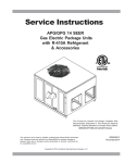
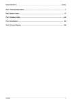
FORMULAS
110
120
130
140
BTU OUTPUT = CFM x 1.08 x RISE
BTU OUTPUT
RISE =
÷ CFM
1.08
BTU OUTPUT vs TEMPERATURE RISE CHART
150
BLOWER PERFORMANCE DATA
TEMPERATURE RISE
75
70
23
6.5
236
109
LO PR
S/T
Delta T
KW
HI PR
0.82
23
1.65
MBh
AMPS
112
21.4
LO PR
1.69
6.7
243
Delta T
KW
AMPS
HI PR
23.2
0.85
MBh
S/T
0.89
22
S/T
Delta T
246
113
23.9
MBh
HI PR
LO PR
108
LO PR
6.7
20
1.64
6.4
233
Delta T
KW
AMPS
HI PR
1.71
0.72
S/T
KW
21.1
MBh
AMPS
6.6
241
111
0.75
20
S/T
Delta T
1.68
22.8
MBh
KW
243
112
HI PR
LO PR
AMPS
HI PR
LO PR
1.69
6.7
19
Delta T
KW
AMPS
0.79
S/T
59
23.5
MBh
63
116
254
6.6
0.74
22
1.69
22.1
119
1.73
6.8
262
21
23.9
0.76
264
121
6.9
1.74
0.80
20
24.6
115
18
1.67
6.6
251
0.60
21.8
6.7
259
118
1.71
0.63
17
23.7
262
119
1.73
6.8
17
0.66
24.4
65
67
126
268
6.8
0.56
18
1.74
23.9
130
1.78
7.0
276
17
25.9
0.58
279
132
7.1
1.79
0.61
17
26.7
125
13
1.72
6.8
265
0.42
23.9
6.9
274
129
1.77
0.43
13
25.9
276
130
1.78
7.0
13
0.46
26.7
59
265
115
135
7.0
0.85
24
1.78
20.9
119
1.82
7.1
273
23
22.7
0.88
276
120
7.2
1.83
0.93
22
23.4
114
21
1.76
6.9
262
0.75
20.6
7.1
270
117
1.80
0.78
20
22.3
273
119
1.82
7.1
19
0.82
23.0
280
7.1
0.36
12
1.79
25.6
139
1.83
7.2
288
12
27.8
0.37
291
140
7.3
1.85
0.39
12
28.6
-
-
-
-
-
-
-
-
-
-
-
-
-
71
63
122
285
7.1
0.76
22
1.81
21.6
126
1.86
7.3
294
22
23.4
0.79
297
127
7.4
1.87
0.83
21
24.1
121
18
1.80
7.1
282
0.63
21.3
7.2
291
125
1.84
0.65
17
23.1
294
126
1.86
7.3
17
0.68
23.8
75
67
142
314
7.6
0.37
12
1.93
25.0
147
1.97
7.8
323
12
27.1
0.39
327
148
7.8
1.99
0.40
12
27.9
-
-
-
-
-
-
-
-
-
-
-
-
-
71
59
120
301
7.5
0.87
24
1.88
20.4
123
1.93
7.7
310
23
22.1
0.91
313
124
7.8
1.94
0.95
22
22.8
118
21
1.87
7.4
298
0.77
20.1
7.6
307
122
1.91
0.80
20
21.8
310
123
1.93
7.7
19
0.84
22.4
Outdoor Ambient Temperature
127
324
7.7
0.78
22
1.92
21.0
131
1.97
7.9
334
22
22.8
0.81
337
132
7.9
1.99
0.85
21
23.5
126
18
1.91
7.6
321
0.64
20.8
7.8
331
130
1.95
0.67
18
22.6
334
131
1.97
7.9
17
0.70
23.2
139
342
7.9
0.59
18
1.98
22.8
143
2.03
8.1
353
18
24.7
0.61
356
145
8.2
2.05
0.64
17
25.4
137
14
1.97
7.8
339
0.44
22.8
8.0
349
142
2.02
0.46
13
24.7
353
143
2.03
8.1
13
0.48
25.5
148
357
8.2
0.38
12
2.05
24.4
152
2.10
8.4
368
12
26.5
0.39
371
154
8.5
2.11
0.41
12
27.3
-
-
-
-
-
-
-
-
-
-
-
-
-
67
146
390
8.4
0.61
18
2.08
22.2
150
2.14
8.6
402
18
24.1
0.63
406
152
8.7
2.15
0.66
17
24.8
144
14
2.07
8.3
386
0.46
22.3
8.6
398
149
2.12
0.48
13
24.1
402
150
2.14
8.6
13
0.50
24.8
155
406
8.7
0.39
12
2.15
23.8
160
2.21
8.9
419
12
25.8
0.41
423
162
9.0
2.22
0.43
12
26.6
-
-
-
-
-
-
-
-
-
-
-
-
-
71
KW = Total system power
134
369
8.2
0.81
22
2.02
20.5
138
8.4
380
22
2.07
22.2
0.84
384
139
8.4
2.09
0.88
21
22.9
132
18
2.00
8.1
365
0.66
20.3
8.3
377
136
2.05
0.69
18
22.0
380
138
2.07
8.4
17
0.72
22.7
95
59
132
386
8.5
0.94
24
2.06
18.9
136
2.11
8.7
398
23
20.5
0.97
402
137
8.7
2.13
1.00
22
21.1
130
20
2.04
8.4
382
0.82
18.6
8.6
394
134
2.09
0.85
20
20.2
398
136
2.11
8.7
19
0.90
20.8
63
140
415
8.6
0.84
22
2.10
19.5
144
2.16
8.9
428
21
21.1
0.87
432
146
8.9
2.17
0.91
20
21.8
139
18
2.09
8.6
411
0.69
19.3
8.8
424
143
2.14
0.71
17
20.9
428
144
2.16
8.9
17
0.75
21.5
105
AMPS: Unit amps (comp.+ evaporator + condenser fan motors)
126
343
8.0
0.90
24
1.98
19.9
129
2.03
8.2
353
24
21.6
0.94
357
131
8.3
2.04
0.98
23
22.2
124
21
1.96
7.9
339
0.79
19.6
8.1
350
128
2.01
0.82
20
21.2
353
129
2.03
8.2
19
0.86
21.9
Entering Indoor Wet Bulb Temperature
63
67
71
59
63
85
NOTE: Shaded area is ACCA (TVA) conditions
134
301
7.3
0.58
18
1.87
23.3
138
1.91
7.5
310
18
25.3
0.60
313
139
7.6
1.93
0.63
17
26.0
132
14
1.85
7.3
298
0.43
23.4
7.5
307
136
1.90
0.45
13
25.3
310
138
1.91
7.5
13
0.47
26.1
High and low pressures are measured at the liquid and suction access fittings.
* IDB: Entering Indoor Dry Bulb Temperature
690
790
890
690
790
890
IDB* Airflow
EXPANDED PERFORMANCE DATA
67
153
438
8.9
0.63
18
2.17
21.1
158
2.23
9.1
452
18
22.9
0.66
456
159
9.2
2.24
0.69
17
23.6
151
13
2.15
8.8
434
0.48
21.1
9.1
447
156
2.21
0.49
13
22.9
452
158
2.22
9.1
13
0.52
23.6
163
457
9.2
0.41
12
2.24
22.7
168
2.30
9.5
471
12
24.5
0.42
476
170
9.6
2.32
0.44
12
25.3
-
-
-
-
-
-
-
-
-
-
-
-
-
71
59
136
426
8.9
0.94
22
2.13
17.5
140
2.18
9.2
439
22
19.0
0.98
444
142
9.2
2.20
1.00
20
19.6
135
19
2.11
8.8
422
0.83
17.3
9.1
435
139
2.16
0.86
19
18.7
439
140
2.18
9.2
18
0.90
19.3
63
145
459
9.1
0.84
20
2.17
18.1
149
2.23
9.4
473
20
19.6
0.88
478
151
9.4
2.25
0.92
19
20.2
143
17
2.16
9.0
454
0.69
17.9
9.3
468
148
2.21
0.72
16
19.4
473
149
2.23
9.4
16
0.75
20.0
115
158
484
9.4
0.64
17
2.24
19.6
163
2.30
9.7
499
16
21.2
0.66
504
165
9.7
2.32
0.70
16
21.8
157
13
2.23
9.3
479
0.48
19.6
9.6
494
161
2.28
0.50
12
21.2
499
163
2.30
9.7
12
0.52
21.9
67
COOLING OPERATION
Design Subcooling, 7 °F @ the liquid access fitting connection AHRI 95 test conditions. Design Superheat 14 °F @ the compressor suction access fitting connection.
MODEL: *PG1324***M41A*
168
505
9.7
0.41
11
2.32
21.0
174
2.38
10.0
521
11
22.7
0.43
526
175
10.1
2.40
0.45
11
23.4
-
-
-
-
-
-
-
-
-
-
-
-
-
71
COOLING PERFORMANCE DATA
*PG1324***M41A*
17
18
85
80
1.73
6.8
251
116
24.0
0.98
27
1.72
6.8
248
115
22.2
0.95
28
1.68
6.6
241
111
MBh
S/T
Delta T
KW
AMPS
HI PR
LO PR
MBh
S/T
Delta T
KW
AMPS
HI PR
LO PR
24.8
1.00
26
MBh
S/T
Delta T
KW
AMPS
HI PR
LO PR
1.67
6.5
238
110
21.8
0.90
26
MBh
S/T
Delta T
KW
AMPS
HI PR
LO PR
1.71
6.7
246
113
23.6
0.94
26
MBh
S/T
Delta T
KW
AMPS
HI PR
LO PR
1.72
6.8
248
115
KW
AMPS
HI PR
LO PR
24.3
1.00
25
118
0.91
28
1.71
6.7
259
22.6
6.9
267
122
24.5
0.95
27
1.75
1.77
7.0
270
123
25.2
0.99
26
1.70
6.7
256
117
22.3
0.85
25
1.74
6.9
264
121
24.1
0.88
25
1.75
6.9
267
122
24.9
0.92
24
129
0.82
26
1.77
6.9
273
23.7
7.1
282
133
25.7
0.85
26
1.81
1.82
7.2
285
134
26.4
0.90
24
1.75
6.9
271
128
23.8
0.69
22
1.79
7.1
279
132
25.8
0.71
21
1.81
7.1
282
133
26.6
0.75
21
137
0.67
23
1.82
7.2
285
25.3
7.4
294
142
27.4
0.69
22
1.86
1.88
7.4
297
143
28.2
0.73
21
1.81
7.1
282
136
25.5
0.51
17
1.85
7.3
291
140
27.6
0.53
17
1.86
7.4
294
142
28.4
0.56
16
125
117
136
0.85
26
1.90
7.5
307
23.1
7.6
316
141
25.1
0.89
26
1.94
1.96
7.7
319
142
25.8
0.93
25
1.88
7.4
304
135
23.3
0.71
22
1.93
7.6
313
139
25.2
0.74
22
1.94
7.6
316
141
26.0
0.78
21
145
0.69
23
1.96
7.7
320
24.7
7.9
330
150
26.8
0.72
22
2.01
2.02
8.0
333
151
27.6
0.75
21
1.94
7.6
317
144
24.9
0.53
18
1.99
7.8
327
148
26.9
0.55
17
2.01
7.9
330
150
27.7
0.58
17
122
1.00
28
1.91
7.6
307
21.2
7.8
317
126
22.9
1.00
27
1.96
1.98
7.9
320
127
23.6
1.00
24
1.90
7.6
304
121
20.8
0.96
27
1.94
7.8
313
125
22.5
0.99
26
1.96
7.8
317
126
23.2
1.00
24
130
0.97
28
1.95
7.8
330
21.6
8.0
341
134
23.4
1.00
27
2.00
2.02
8.1
344
135
24.1
1.00
25
1.94
7.7
327
128
21.3
0.90
25
1.99
7.9
337
132
23.0
0.93
25
2.00
8.0
341
134
23.7
1.00
24
IDB: Entering Indoor Dry Bulb Temperature
0.95
28
1.84
7.2
291
22.1
7.4
300
129
23.9
0.98
27
1.89
1.90
7.5
303
130
24.7
1.00
25
1.83
7.2
288
124
21.8
0.88
25
1.87
7.4
297
127
23.6
0.91
25
1.89
7.4
300
129
24.3
0.95
24
0.98
28
1.80
7.1
270
21.7
7.3
278
121
23.5
1.00
27
1.85
1.86
7.3
281
122
24.2
1.00
25
1.79
7.0
267
116
21.3
0.93
27
1.83
7.2
276
120
23.1
0.97
26
1.85
7.3
278
121
23.8
1.00
25
High and low pressures are measured at the liquid and suction access fittings.
* NOTE: Shaded area reflects AHRI rating conditions
690
790
890
690
790
890
MBh
S/T
Delta T
EXPANDED PERFORMANCE DATA
142
0.88
26
2.01
8.0
349
22.6
8.3
360
146
24.5
0.91
26
2.06
2.08
8.3
363
148
25.2
0.95
25
2.00
8.0
346
140
22.7
0.73
22
2.05
8.2
356
145
24.6
0.76
22
2.06
8.3
360
146
25.3
0.80
21
128
1.00
28
2.01
8.1
350
20.6
8.3
361
132
22.4
1.00
26
2.06
2.08
8.4
364
133
23.0
1.00
24
1.99
8.0
346
127
20.3
0.99
27
2.04
8.3
357
131
22.0
1.00
26
2.06
8.3
361
132
22.6
1.00
23
149
0.90
27
2.12
8.6
397
22.0
8.8
410
153
23.9
0.94
26
2.17
2.19
8.9
414
155
24.6
0.98
25
2.10
8.5
394
147
22.2
0.76
22
406
152
2.15
8.7
24.0
0.78
22
2.17
8.8
410
153
24.7
0.82
21
158
0.73
23
2.19
8.9
415
23.5
9.1
427
163
25.5
0.76
23
2.24
2.26
9.2
432
165
26.2
0.80
22
2.17
8.8
410
157
23.7
0.56
18
2.22
9.0
423
162
25.7
0.59
17
2.24
9.1
427
163
26.4
0.61
17
KW = Total system power
136
1.00
28
2.05
8.3
376
21.0
8.5
388
141
22.8
1.00
27
2.10
2.12
8.6
392
142
23.5
1.00
24
2.04
8.2
373
135
20.7
0.93
26
2.09
8.4
384
139
22.5
0.96
25
2.10
8.5
388
141
23.1
1.00
24
134
1.00
26
2.09
8.6
393
19.6
8.8
406
138
21.2
1.00
25
2.14
2.16
8.9
410
140
21.9
1.00
23
2.08
8.5
390
133
19.3
1.03
26
2.13
8.7
402
137
20.9
1.00
24
2.14
8.8
406
138
21.5
1.00
22
143
1.00
27
2.14
8.8
423
20.0
9.0
437
147
21.7
1.00
25
2.19
2.21
9.1
441
149
22.3
1.00
23
2.12
8.7
419
141
19.7
0.96
25
2.17
8.9
432
146
21.3
1.00
25
2.19
9.0
437
147
22.0
1.00
23
AMPS: Unit amps (comp.+ evaporator + condenser fan motors)
151
0.71
23
2.08
8.3
364
24.1
8.5
375
156
26.1
0.74
22
2.13
2.15
8.6
379
157
26.9
0.77
21
2.06
8.3
360
149
24.3
0.55
18
2.11
8.5
372
154
26.3
0.57
17
2.13
8.5
375
156
27.1
0.59
17
156
0.94
26
2.21
9.1
447
20.9
9.3
461
161
22.7
0.97
26
2.26
2.28
9.4
466
162
23.4
1.00
24
2.19
9.0
443
154
21.0
0.78
22
2.24
9.2
456
159
22.8
0.81
22
2.26
9.3
461
161
23.5
0.85
21
166
0.76
23
2.28
9.4
466
22.3
9.6
481
171
24.2
0.79
22
2.34
2.36
9.7
486
173
24.9
0.83
21
2.26
9.3
462
164
22.5
0.59
18
2.32
9.6
476
170
24.4
0.61
17
2.34
9.6
481
171
25.1
0.64
17
139
1.00
24
2.16
9.1
435
18.2
9.3
448
143
19.7
1.00
23
2.22
2.24
9.4
453
145
20.3
1.00
21
2.15
9.0
430
138
17.9
1.04
25
2.20
9.2
444
142
19.3
1.00
23
2.22
9.3
448
143
19.9
1.00
21
148
1.00
25
2.21
9.3
468
18.5
9.5
482
152
20.1
1.00
23
2.27
2.29
9.6
487
154
20.7
1.00
21
2.19
9.2
463
146
18.2
0.97
24
2.25
9.4
478
151
19.8
1.00
23
2.27
9.5
482
152
20.4
1.00
21
115
161
0.95
24
2.28
9.6
494
19.4
9.8
509
166
21.0
0.98
24
2.34
2.36
9.9
514
168
21.6
1.00
22
2.26
9.5
489
160
19.5
0.79
21
2.32
9.7
504
165
21.1
0.82
20
2.34
9.8
509
166
21.8
0.86
19
COOLING OPERATION
Design Subcooling, 7 °F @ the liquid access fitting connection AHRI 95 test conditions. Design Superheat 14 °F @ the compressor suction access fitting connection.
Outdoor Ambient Temperature
65
75
85
95
105
Entering Indoor Wet Bulb Temperature
MODEL: *PG1324***M41A*
172
0.77
21
2.36
9.9
515
20.7
10.2
531
177
22.4
0.80
21
2.42
2.44
10.3
537
179
23.1
0.83
20
2.34
9.8
510
170
20.8
0.59
16
2.40
10.1
526
175
22.6
0.61
16
2.42
10.2
531
177
23.3
0.64
15
COOLING PERFORMANCE DATA
*PG1324***M41A*
75
70
IDB*
22
7.5
231
111
LO PR
S/T
Delta T
KW
HI PR
0.83
22
2.04
MBh
AMPS
114
25.5
LO PR
2.09
7.7
238
Delta T
KW
AMPS
HI PR
27.7
0.86
MBh
S/T
0.90
21
S/T
Delta T
241
116
28.5
MBh
HI PR
LO PR
110
LO PR
7.8
19
2.03
7.4
229
Delta T
KW
AMPS
HI PR
2.10
0.73
S/T
KW
25.1
MBh
AMPS
7.6
236
113
0.76
19
S/T
Delta T
2.07
27.2
MBh
KW
238
114
HI PR
LO PR
AMPS
HI PR
LO PR
2.09
7.7
18
Delta T
KW
AMPS
0.79
S/T
59
28.0
MBh
63
118
249
7.7
0.74
21
2.08
26.3
122
2.13
7.9
256
20
28.5
0.77
259
123
7.9
2.14
0.81
19
29.3
117
17
2.07
7.6
246
0.61
26.0
7.8
254
120
2.11
0.63
16
28.2
256
122
2.13
7.9
16
0.66
29.0
65
67
129
263
7.9
0.56
17
2.14
28.5
133
2.19
8.1
271
17
30.8
0.58
273
134
8.2
2.21
0.61
16
31.8
128
13
2.13
7.8
260
0.42
28.5
8.0
268
131
2.18
0.44
12
30.9
271
133
2.19
8.1
12
0.46
31.8
137
274
8.2
0.36
12
2.21
30.5
141
2.26
8.4
282
11
33.1
0.37
285
143
8.5
2.28
0.39
11
34.1
-
-
-
-
-
-
-
-
-
-
-
-
-
71
59
117
259
8.1
0.86
23
2.19
24.9
121
2.24
8.3
267
22
27.0
0.89
270
122
8.3
2.25
0.94
21
27.8
116
20
2.17
8.0
257
0.76
24.5
8.2
265
120
2.22
0.78
19
26.6
267
121
2.24
8.3
18
0.82
27.4
63
125
279
8.2
0.77
21
2.23
25.7
129
2.28
8.5
288
20
27.8
0.80
291
130
8.5
2.30
0.84
20
28.7
123
17
2.21
8.2
276
0.63
25.4
8.4
285
127
2.27
0.66
17
27.5
288
129
2.28
8.5
16
0.69
28.4
75
67
145
307
8.8
0.37
12
2.37
29.8
149
2.42
9.0
317
12
32.3
0.39
320
151
9.1
2.44
0.41
11
33.3
-
-
-
-
-
-
-
-
-
-
-
-
-
71
59
122
295
8.7
0.88
23
2.32
24.4
126
2.37
8.9
304
22
26.4
0.91
307
127
9.0
2.39
0.96
21
27.2
121
20
2.30
8.6
292
0.78
23.9
8.9
301
124
2.35
0.80
19
25.9
304
126
2.37
8.9
18
0.84
26.7
Outdoor Ambient Temperature
130
317
8.9
0.79
21
2.36
25.1
134
2.42
9.1
327
20
27.2
0.82
330
135
9.2
2.44
0.86
20
28.0
128
17
2.34
8.8
314
0.65
24.8
9.1
324
132
2.40
0.67
17
26.9
327
134
2.42
9.1
16
0.70
27.7
141
335
9.2
0.60
17
2.44
27.1
146
2.49
9.4
346
17
29.4
0.62
349
147
9.5
2.51
0.65
16
30.3
140
13
2.42
9.1
332
0.45
27.2
9.4
342
144
2.47
0.47
13
29.5
345
146
2.49
9.4
12
0.49
30.3
151
350
9.5
0.38
12
2.51
29.1
155
2.57
9.8
360
12
31.6
0.40
364
157
9.9
2.59
0.42
11
32.5
-
-
-
-
-
-
-
-
-
-
-
-
-
67
149
382
9.8
0.62
17
2.56
26.5
153
2.62
10.1
394
17
28.7
0.64
397
155
10.1
2.64
0.67
16
29.5
147
13
2.54
9.7
378
0.46
26.5
10.0
390
152
2.60
0.48
13
28.7
393
153
2.62
10.0
12
0.50
29.6
158
398
10.1
0.40
12
2.64
28.4
163
2.70
10.4
410
12
30.8
0.41
415
165
10.5
2.72
0.43
11
31.7
-
-
-
-
-
-
-
-
-
-
-
-
-
71
KW = Total system power
136
361
9.5
0.81
21
2.48
24.5
140
9.7
373
21
2.54
26.5
0.84
376
142
9.8
2.56
0.89
20
27.3
135
17
2.46
9.4
358
0.67
24.2
9.7
369
139
2.52
0.69
17
26.2
373
140
2.54
9.7
16
0.73
27.0
95
59
134
378
9.8
0.94
22
2.53
22.6
138
2.59
10.1
390
22
24.5
0.98
393
140
10.2
2.61
1.00
21
25.2
133
19
2.51
9.7
374
0.83
22.2
10.0
386
137
2.57
0.86
19
24.0
390
138
2.59
10.1
18
0.90
24.8
63
143
407
10.1
0.85
21
2.58
23.2
147
2.64
10.3
419
20
25.2
0.88
423
149
10.4
2.66
0.92
19
25.9
141
17
2.56
10.0
403
0.69
23.0
10.2
415
146
2.62
0.72
16
24.9
419
147
2.64
10.3
16
0.75
25.7
105
AMPS: Unit amps (comp.+ evaporator + condenser fan motors)
128
336
9.3
0.91
23
2.43
23.8
132
2.49
9.5
346
22
25.7
0.94
350
133
9.6
2.51
0.99
21
26.5
127
20
2.41
9.2
333
0.80
23.4
9.4
343
131
2.47
0.83
19
25.3
346
132
2.49
9.5
19
0.87
26.1
Entering Indoor Wet Bulb Temperature
63
67
71
59
63
85
NOTE: Shaded area is ACCA (TVA) conditions
136
295
8.5
0.58
17
2.30
27.8
140
2.35
8.7
304
17
30.1
0.60
307
142
8.8
2.37
0.63
16
31.0
135
13
2.28
8.4
292
0.44
27.9
8.6
301
139
2.33
0.45
13
30.2
304
140
2.35
8.7
12
0.48
31.1
High and low pressures are measured at the liquid and suction access fittings.
* IDB: Entering Indoor Dry Bulb Temperature
875
1000
1125
875
1000
1125
Airflow
EXPANDED PERFORMANCE DATA
67
156
429
10.4
0.64
17
2.66
25.2
161
2.73
10.7
443
17
27.3
0.66
447
162
10.8
2.75
0.70
16
28.1
154
13
2.64
10.3
425
0.48
25.2
10.6
438
159
2.70
0.50
13
27.3
443
161
2.72
10.7
12
0.52
28.1
166
448
10.8
0.41
12
2.74
27.0
171
2.81
11.1
462
11
29.2
0.43
466
173
11.2
2.84
0.45
11
30.1
-
-
-
-
-
-
-
-
-
-
-
-
-
71
59
139
418
10.4
0.95
21
2.61
20.9
143
2.67
10.7
430
21
22.7
0.99
435
144
10.8
2.69
1.00
19
23.3
137
18
2.59
10.3
413
0.84
20.6
10.6
426
142
2.65
0.87
18
22.3
430
143
2.67
10.7
17
0.91
22.9
63
148
449
10.6
0.85
19
2.66
21.5
152
2.73
10.9
463
19
23.3
0.88
468
154
11.0
2.75
0.93
18
24.0
146
16
2.64
10.5
445
0.70
21.3
10.8
459
151
2.71
0.73
15
23.1
463
152
2.73
10.9
15
0.76
23.8
115
161
474
11.0
0.64
16
2.75
23.3
166
2.82
11.3
489
16
25.2
0.67
494
168
11.4
2.84
0.70
15
26.0
159
12
2.73
10.9
470
0.48
23.3
11.2
484
164
2.79
0.50
12
25.3
489
166
2.82
11.3
11
0.53
26.1
67
COOLING OPERATION
Design Subcooling, 7 °F @ the liquid access fitting connection AHRI 95 test conditions. Design Superheat 5°F @ the compressor suction access fitting connection.
MODEL: *GP1330***M41A*
172
495
11.4
0.41
11
2.84
25.0
177
2.91
11.7
510
11
27.1
0.43
515
179
11.8
2.93
0.45
10
27.9
-
-
-
-
-
-
-
-
-
-
-
-
-
71
COOLING PERFORMANCE DATA
*PG1330***M41A*
19
20
85
80
2.13
7.9
245
118
28.7
0.99
26
2.12
7.8
243
117
26.4
0.95
27
2.07
7.6
236
113
MBh
S/T
Delta T
KW
AMPS
HI PR
LO PR
MBh
S/T
Delta T
KW
AMPS
HI PR
LO PR
29.5
1.00
24
MBh
S/T
Delta T
KW
AMPS
HI PR
LO PR
2.06
7.6
233
112
26.0
0.91
25
MBh
S/T
Delta T
KW
AMPS
HI PR
LO PR
2.10
7.8
241
116
28.2
0.94
24
MBh
S/T
Delta T
KW
AMPS
HI PR
LO PR
2.12
7.8
243
117
KW
AMPS
HI PR
LO PR
29.0
1.00
24
120
0.92
26
2.11
7.8
254
27.0
8.0
262
124
29.2
0.95
26
2.16
2.18
8.1
264
125
30.1
1.00
25
2.10
7.7
251
119
26.6
0.85
24
2.15
7.9
259
123
28.8
0.89
23
2.16
8.0
262
124
29.6
0.93
22
131
0.83
25
2.17
8.0
268
28.2
8.2
276
136
30.6
0.86
24
2.23
2.24
8.3
279
137
31.5
0.90
23
2.16
8.0
265
130
28.4
0.69
21
2.21
8.2
273
134
30.7
0.72
20
2.23
8.2
276
136
31.7
0.76
20
140
0.67
21
2.24
8.3
279
30.1
8.5
288
144
32.6
0.70
21
2.29
2.31
8.6
291
146
33.6
0.73
20
2.22
8.2
277
139
30.3
0.52
17
2.28
8.5
285
143
32.9
0.54
16
2.29
8.5
288
144
33.9
0.56
16
127
120
139
0.86
25
2.33
8.6
301
27.6
8.9
310
143
29.9
0.89
25
2.39
2.41
8.9
313
145
30.8
0.94
24
2.32
8.6
298
137
27.7
0.72
21
2.37
8.8
307
142
30.0
0.75
21
2.39
8.9
310
143
30.9
0.78
20
148
0.70
22
2.41
8.9
314
29.4
9.2
323
152
31.9
0.72
21
2.46
2.48
9.3
326
154
32.8
0.76
20
2.39
8.9
310
146
29.6
0.54
17
2.44
9.1
320
151
32.1
0.56
16
2.46
9.2
323
152
33.1
0.59
16
124
1.00
26
2.35
8.9
301
25.2
9.1
310
128
27.3
1.00
25
2.41
2.43
9.2
313
129
28.1
1.00
23
2.33
8.8
298
123
24.8
0.97
25
2.39
9.0
307
127
26.9
1.00
25
2.41
9.1
310
128
27.7
1.00
23
132
0.98
26
2.40
9.1
324
25.7
9.3
334
136
27.9
1.00
26
2.46
2.48
9.4
337
138
28.7
1.00
23
2.38
9.0
321
131
25.3
0.91
24
2.44
9.2
331
135
27.4
0.94
24
2.46
9.3
334
136
28.3
1.00
23
IDB: Entering Indoor Dry Bulb Temperature
0.95
26
2.27
8.4
285
26.3
8.6
294
131
28.5
0.99
26
2.32
2.34
8.7
296
132
29.4
1.00
24
2.25
8.3
282
126
25.9
0.88
24
2.30
8.5
291
130
28.1
0.92
24
2.32
8.6
294
131
29.0
0.96
23
0.99
27
2.22
8.2
265
25.8
8.4
273
123
28.0
1.00
26
2.27
2.29
8.5
275
125
28.8
1.00
24
2.20
8.1
262
118
25.4
0.94
25
2.26
8.3
270
122
27.5
0.98
25
2.27
8.4
273
123
28.3
1.00
23
High and low pressures are measured at the liquid and suction access fittings.
* NOTE: Shaded area reflects AHRI rating conditions
875
1000
1125
875
1000
1125
MBh
S/T
Delta T
EXPANDED PERFORMANCE DATA
144
0.88
25
2.47
9.3
342
26.9
9.6
352
149
29.2
0.92
25
2.53
2.55
9.7
356
150
30.0
0.96
24
2.45
9.3
339
143
27.1
0.74
21
2.51
9.5
349
147
29.3
0.77
21
2.53
9.6
352
149
30.2
0.80
20
131
1.00
26
2.47
9.4
343
24.6
9.7
353
135
26.7
1.00
25
2.53
2.55
9.8
357
136
27.5
1.00
22
2.45
9.4
339
129
24.2
1.00
25
2.51
9.6
350
133
26.2
1.00
24
2.53
9.7
353
135
27.0
1.00
22
152
0.91
25
2.60
10.0
389
26.3
10.2
401
156
28.5
0.95
25
2.66
2.68
10.3
405
158
29.3
0.99
24
2.58
9.9
386
150
26.4
0.76
21
398
155
2.64
10.1
28.6
0.79
21
2.66
10.2
401
156
29.5
0.83
20
161
0.74
22
2.68
10.3
406
28.0
10.6
419
166
30.4
0.77
21
2.75
2.77
10.7
423
168
31.3
0.80
21
2.66
10.2
402
160
28.2
0.57
17
2.72
10.5
415
165
30.6
0.59
17
2.75
10.6
419
166
31.5
0.62
16
KW = Total system power
139
1.00
26
2.52
9.7
369
25.1
9.9
380
143
27.2
1.00
25
2.58
2.60
10.0
384
145
28.0
1.00
23
2.50
9.6
365
137
24.7
0.94
24
2.56
9.8
376
142
26.8
0.97
24
2.58
9.9
380
143
27.6
1.00
23
137
1.00
25
2.57
10.0
386
23.4
10.3
397
141
25.3
1.00
23
2.63
2.65
10.4
401
142
26.1
1.00
21
2.55
9.9
382
135
23.0
1.04
25
2.61
10.2
394
140
24.9
1.00
23
2.63
10.3
397
141
25.6
1.00
21
146
1.00
25
2.62
10.2
415
23.8
10.5
428
150
25.8
1.00
24
2.68
2.71
10.6
432
152
26.6
1.00
22
2.60
10.2
411
144
23.5
0.97
24
2.66
10.4
423
149
25.4
1.00
23
2.68
10.5
428
150
26.2
1.00
21
AMPS: Unit amps (comp.+ evaporator + condenser fan motors)
154
0.72
22
2.55
9.7
357
28.7
9.9
368
158
31.1
0.74
21
2.61
2.63
10.0
371
160
32.1
0.78
20
2.53
9.6
353
152
28.9
0.55
17
2.59
9.9
364
157
31.3
0.57
16
2.61
9.9
368
158
32.3
0.60
16
159
0.95
25
2.70
10.6
438
25.0
10.9
452
164
27.0
0.98
24
2.77
2.79
11.0
456
165
27.8
1.00
23
2.68
10.5
434
157
25.1
0.79
21
2.75
10.8
447
162
27.2
0.82
20
2.77
10.9
452
164
28.0
0.86
20
169
0.77
21
2.79
11.0
457
26.6
11.3
471
174
28.8
0.80
21
2.86
2.88
11.4
476
176
29.7
0.83
20
2.77
10.9
452
168
26.8
0.59
17
2.84
11.2
466
173
29.0
0.61
16
2.86
11.3
471
174
29.9
0.64
16
141
1.00
23
2.65
10.6
426
21.7
10.9
439
146
23.5
1.00
22
2.72
2.74
11.0
444
147
24.2
1.00
20
2.63
10.5
422
140
21.3
1.04
23
2.69
10.8
435
144
23.1
1.00
21
2.72
10.9
439
146
23.7
1.00
19
151
1.00
23
2.71
10.8
458
22.1
11.1
473
155
23.9
1.00
22
2.77
2.80
11.2
477
157
24.6
1.00
20
2.69
10.7
454
149
21.7
0.98
22
2.75
11.0
468
154
23.6
1.00
22
2.77
11.1
473
155
24.3
1.00
20
115
164
0.95
23
2.79
11.2
484
23.1
11.5
499
169
25.0
0.99
23
2.86
2.89
11.6
504
171
25.8
1.00
21
2.77
11.1
479
163
23.2
0.80
19
2.84
11.4
494
168
25.2
0.83
19
2.86
11.5
499
169
25.9
0.87
18
COOLING OPERATION
Design Subcooling, 7 °F @ the liquid access fitting connection AHRI 95 test conditions. Design Superheat 5°F @ the compressor suction access fitting connection.
Outdoor Ambient Temperature
65
75
85
95
105
Entering Indoor Wet Bulb Temperature
MODEL: *GP1330***M41A*
175
0.77
20
2.88
11.6
505
24.7
11.9
520
180
26.7
0.80
20
2.96
2.98
12.0
526
182
27.5
0.84
19
2.86
11.5
500
173
24.8
0.60
16
2.93
11.8
515
179
26.9
0.62
15
2.96
11.9
520
180
27.7
0.65
15
COOLING PERFORMANCE DATA
*PG1330***M41A*
75
70
IDB*
22
111
32.0
0.82
23
2.51
10.8
242
108
LO PR
MBh
S/T
Delta T
KW
AMPS
HI PR
LO PR
2.57
11.1
249
Delta T
KW
AMPS
HI PR
34.6
0.85
0.89
22
S/T
Delta T
MBh
S/T
35.7
MBh
252
113
107
LO PR
HI PR
LO PR
20
2.49
10.8
240
Delta T
KW
AMPS
HI PR
11.2
0.72
S/T
2.59
31.4
MBh
KW
11.0
247
110
AMPS
2.55
0.74
19
S/T
Delta T
KW
34.1
MBh
AMPS
HI PR
LO PR
249
111
HI PR
LO PR
19
2.57
11.1
Delta T
KW
AMPS
0.78
S/T
59
35.1
MBh
63
115
260
11.1
0.73
21
2.56
32.9
119
2.62
11.3
268
21
35.7
0.76
271
120
11.4
2.64
0.79
20
36.7
114
17
2.54
11.0
258
0.60
32.6
11.2
266
117
2.60
0.62
17
35.3
268
119
2.62
11.3
16
0.65
36.4
65
67
126
275
11.4
0.55
17
2.64
35.6
129
2.70
11.6
283
17
38.6
0.57
286
131
11.7
2.72
0.60
16
39.8
124
13
2.62
11.3
272
0.41
35.7
11.5
281
128
2.68
0.43
13
38.7
283
129
2.70
11.6
12
0.45
39.8
134
287
11.7
0.35
12
2.72
38.2
138
2.79
12.0
296
12
41.4
0.37
299
139
12.1
2.81
0.39
11
42.7
-
-
-
-
-
-
-
-
-
-
-
-
-
71
59
114
272
11.6
0.84
23
2.70
31.2
118
2.76
11.8
280
23
33.8
0.88
283
119
11.9
2.78
0.92
22
34.8
113
20
2.68
11.5
269
0.74
30.7
11.7
277
117
2.74
0.77
20
33.3
280
118
2.76
11.8
19
0.81
34.3
63
122
292
11.8
0.76
21
2.75
32.2
125
2.82
12.1
301
21
34.8
0.78
304
127
12.2
2.84
0.82
20
35.9
120
17
2.73
11.7
289
0.62
31.8
12.0
298
124
2.80
0.64
17
34.5
301
125
2.82
12.1
16
0.67
35.5
75
67
141
322
12.5
0.37
12
2.92
37.3
146
3.00
12.8
332
12
40.5
0.38
335
147
12.9
3.02
0.40
11
41.7
-
-
-
-
-
-
-
-
-
-
-
-
-
71
59
119
309
12.4
0.87
23
2.86
30.5
122
2.93
12.7
318
23
33.0
0.90
322
124
12.8
2.95
0.94
22
34.0
118
20
2.84
12.3
306
0.76
30.0
12.6
315
121
2.90
0.79
20
32.5
318
122
2.93
12.7
19
0.83
33.4
Outdoor Ambient Temperature
126
332
12.6
0.77
21
2.92
31.4
130
2.99
12.9
343
21
34.0
0.80
346
131
13.0
3.01
0.84
20
35.0
125
17
2.89
12.5
329
0.64
31.1
12.8
339
129
2.97
0.66
17
33.7
343
130
2.99
12.9
16
0.69
34.7
138
351
13.0
0.59
17
3.01
34.0
142
3.08
13.3
362
17
36.8
0.61
365
144
13.4
3.11
0.64
16
37.9
136
13
2.98
12.9
347
0.44
34.0
13.2
358
141
3.06
0.46
13
36.9
362
142
3.08
13.3
12
0.48
38.0
147
366
13.4
0.38
12
3.10
36.5
151
3.18
13.7
377
12
39.5
0.39
381
153
13.8
3.21
0.41
11
40.7
-
-
-
-
-
-
-
-
-
-
-
-
-
67
145
400
13.8
0.61
18
3.16
33.1
149
3.24
14.1
412
17
35.9
0.63
416
151
14.2
3.27
0.66
17
37.0
143
13
3.14
13.6
396
0.46
33.2
14.0
408
148
3.21
0.47
13
36.0
412
149
3.24
14.1
12
0.49
37.1
154
417
14.2
0.39
12
3.26
35.6
159
3.34
14.5
430
12
38.5
0.40
434
161
14.7
3.37
0.42
11
39.7
-
-
-
-
-
-
-
-
-
-
-
-
-
71
KW = Total system power
133
378
13.4
0.80
21
3.06
30.6
137
13.7
390
21
3.14
33.2
0.83
394
138
13.8
3.17
0.87
20
34.2
131
17
3.04
13.3
375
0.66
30.3
13.6
386
135
3.11
0.68
17
32.8
390
137
3.14
13.7
16
0.71
33.8
95
59
131
396
13.8
0.93
23
3.12
28.3
135
3.20
14.2
408
23
30.6
0.96
412
136
14.3
3.23
1.00
21
31.5
129
20
3.10
13.7
392
0.82
27.8
14.0
404
133
3.17
0.85
20
30.1
408
135
3.20
14.1
19
0.89
31.0
63
139
426
14.1
0.83
21
3.19
29.1
143
3.27
14.5
439
21
31.5
0.86
443
145
14.6
3.29
0.90
20
32.5
138
17
3.16
14.0
422
0.68
28.8
14.3
435
142
3.24
0.71
17
31.2
439
143
3.27
14.4
16
0.74
32.1
105
AMPS: Unit amps (comp.+ evaporator + condenser fan motors)
125
352
13.1
0.89
23
3.00
29.7
129
3.07
13.4
363
23
32.2
0.93
366
130
13.5
3.10
0.97
22
33.2
123
20
2.98
13.0
348
0.79
29.2
13.3
359
127
3.05
0.82
20
31.7
363
129
3.07
13.4
19
0.86
32.6
Entering Indoor Wet Bulb Temperature
63
67
71
59
63
85
NOTE: Shaded area is ACCA (TVA) conditions
133
309
12.1
0.57
17
2.84
34.8
137
2.90
12.4
318
17
37.7
0.59
321
138
12.5
2.93
0.62
16
38.8
131
13
2.81
12.0
305
0.43
34.9
12.3
315
135
2.88
0.45
13
37.8
318
137
2.90
12.4
12
0.47
38.9
High and low pressures are measured at the liquid and suction access fittings.
* IDB: Entering Indoor Dry Bulb Temperature
1050
1200
1350
1050
1200
1350
Airflow
EXPANDED PERFORMANCE DATA
67
152
450
14.5
0.63
17
3.29
31.5
156
3.37
14.9
464
17
34.1
0.65
468
158
15.0
3.40
0.68
16
35.1
150
13
3.26
14.4
445
0.47
31.5
14.7
459
155
3.35
0.49
13
34.2
463
156
3.37
14.9
12
0.51
35.2
162
469
15.0
0.40
12
3.40
33.8
167
3.48
15.4
483
12
36.6
0.42
488
168
15.5
3.51
0.44
11
37.7
-
-
-
-
-
-
-
-
-
-
-
-
-
71
59
135
437
14.5
0.94
21
3.23
26.2
139
3.31
14.9
451
21
28.4
0.97
455
141
15.0
3.33
1.00
20
29.2
134
19
3.20
14.4
433
0.82
25.7
14.8
446
138
3.28
0.85
18
27.9
451
139
3.31
14.9
18
0.90
28.7
63
144
470
14.8
0.84
20
3.30
26.9
148
3.38
15.2
485
19
29.2
0.87
490
150
15.3
3.41
0.91
19
30.1
142
16
3.27
14.7
466
0.69
26.7
15.1
480
147
3.35
0.71
16
28.9
485
148
3.38
15.2
15
0.75
29.8
115
157
497
15.3
0.63
16
3.40
29.2
162
3.49
15.6
512
16
31.6
0.66
517
163
15.8
3.52
0.69
15
32.5
155
12
3.37
15.1
492
0.48
29.2
15.5
507
160
3.46
0.49
12
31.7
512
162
3.49
15.6
12
0.52
32.6
67
COOLING OPERATION
Design Subcooling,10 °F @ the liquid access fitting connection AHRI 95 test conditions. Design Superheat 6 °F @ the compressor suction access fitting connection.
MODEL: *PG1336***M41A*
167
518
15.8
0.41
11
3.51
31.3
172
3.60
16.2
534
11
33.9
0.42
540
174
16.3
3.63
0.44
11
34.9
-
-
-
-
-
-
-
-
-
-
-
-
-
71
COOLING PERFORMANCE DATA
*PG1336***M41A*
21
22
85
80
IDB*
27
114
33.1
0.94
27
2.55
11.0
247
110
LO PR
MBh
S/T
Delta T
KW
AMPS
HI PR
LO PR
2.61
11.3
255
Delta T
KW
AMPS
HI PR
35.9
0.97
MBh
S/T
1.00
25
S/T
Delta T
257
115
36.9
MBh
HI PR
LO PR
109
LO PR
11.3
25
2.53
10.9
244
Delta T
KW
AMPS
HI PR
2.63
0.89
S/T
KW
32.5
MBh
AMPS
11.2
252
113
0.93
25
S/T
Delta T
2.59
35.3
MBh
KW
255
114
HI PR
LO PR
AMPS
HI PR
LO PR
2.61
11.3
KW
AMPS
25
117
266
11.2
0.90
27
2.60
33.7
121
2.66
11.5
274
26
36.6
0.94
277
122
11.6
2.68
0.98
25
37.7
116
24
2.58
11.1
263
0.84
33.2
11.4
271
120
2.64
0.87
24
36.0
274
121
2.66
11.5
23
0.91
1.00
S/T
Delta T
63
37.1
59
36.3
MBh
65
67
128
281
11.5
0.82
25
2.68
35.3
132
2.74
11.8
289
25
38.3
0.85
292
133
11.9
2.77
0.89
24
39.4
127
21
2.66
11.4
278
0.68
35.5
11.7
286
131
2.72
0.71
21
38.5
289
132
2.74
11.8
20
0.74
39.6
71
136
293
11.9
0.66
22
2.76
37.7
141
2.83
12.2
302
21
40.9
0.69
305
142
12.2
2.85
0.72
21
42.1
135
17
2.74
11.8
290
0.51
38.0
12.1
299
139
2.81
0.53
17
41.1
302
141
2.83
12.2
16
0.55
42.4
59
117
277
11.7
0.97
27
2.74
32.3
120
2.80
12.0
286
27
35.0
1.00
288
121
12.1
2.83
1.00
25
36.1
115
26
2.72
11.6
274
0.93
31.8
11.9
283
119
2.78
0.96
25
34.4
286
120
2.80
12.0
24
1.00
35.5
63
67
135
315
12.3
0.85
26
2.88
34.5
140
2.95
12.6
325
25
37.4
0.88
328
141
12.7
2.97
0.92
24
38.5
134
21
2.86
12.2
312
0.71
34.7
12.5
321
138
2.93
0.73
21
37.6
325
140
2.95
12.6
20
0.77
38.7
71
144
328
12.7
0.69
22
2.97
36.8
149
3.04
13.0
338
22
39.9
0.71
342
150
13.1
3.07
0.75
21
41.1
143
17
2.95
12.6
325
0.53
37.1
12.9
335
147
3.02
0.55
17
40.2
338
149
3.04
13.0
16
0.57
41.4
59
121
315
12.6
1.00
28
2.90
31.6
125
2.97
12.9
325
26
34.2
1.00
328
126
13.0
3.00
1.00
24
35.2
120
26
2.88
12.5
312
0.95
31.0
12.8
322
124
2.95
0.99
25
33.6
325
125
2.97
12.9
24
1.00
34.6
Outdoor Ambient Temperature
129
339
12.8
0.96
27
2.96
32.2
133
3.04
13.1
350
27
34.9
1.00
353
134
13.2
3.06
1.00
24
35.9
128
25
2.94
12.7
336
0.89
31.7
13.0
346
132
3.01
0.92
24
34.3
350
133
3.04
13.1
23
0.97
35.4
141
358
13.2
0.87
26
3.06
33.7
145
3.13
13.5
369
25
36.5
0.90
373
146
13.6
3.16
0.94
24
37.6
139
22
3.03
13.1
354
0.73
33.9
13.4
365
144
3.11
0.75
21
36.7
369
145
3.13
13.5
20
0.79
37.8
127
359
13.3
1.00
27
3.05
30.8
131
3.12
13.6
370
26
33.4
1.00
374
132
13.7
3.15
1.00
23
34.4
126
26
3.03
13.2
355
0.98
30.3
13.5
366
130
3.10
1.00
25
32.8
370
131
3.12
13.6
23
1.00
33.8
67
148
408
14.0
0.90
26
3.21
32.9
152
3.29
14.3
420
25
35.6
0.93
425
154
14.4
3.32
0.97
24
36.7
146
22
3.19
13.9
404
0.75
33.0
416
151
14.2
0.78
21
3.27
35.8
420
152
3.29
14.3
20
0.81
36.9
71
157
425
14.4
0.73
22
3.32
35.1
162
3.40
14.8
438
22
38.0
0.75
443
164
14.9
3.43
0.79
21
39.1
156
17
3.29
14.3
421
0.56
35.3
14.7
434
161
3.37
0.58
17
38.3
438
162
3.40
14.8
16
0.61
39.4
KW = Total system power
135
386
13.6
0.99
27
3.11
31.4
140
3.19
13.9
398
26
34.0
1.00
402
141
14.0
3.22
1.00
24
35.0
134
25
3.09
13.5
382
0.92
30.9
13.8
394
138
3.17
0.95
24
33.5
398
140
3.19
13.9
24
1.00
34.5
95
59
133
404
14.0
1.00
26
3.17
29.3
137
3.25
14.4
416
24
31.7
1.00
420
139
14.5
3.28
1.00
22
32.6
132
26
3.15
13.9
400
1.02
28.8
14.3
412
136
3.23
1.00
24
31.2
416
137
3.25
14.4
22
1.00
32.1
63
142
434
14.3
1.00
26
3.24
29.8
146
3.32
14.7
448
25
32.3
1.00
452
148
14.8
3.35
1.00
23
33.3
140
25
3.22
14.2
430
0.95
29.4
14.6
443
145
3.30
0.99
24
31.8
448
146
3.32
14.7
22
1.00
32.8
105
AMPS: Unit amps (comp.+ evaporator + condenser fan motors)
150
373
13.6
0.70
22
3.15
36.0
154
3.23
13.9
385
22
39.0
0.73
389
156
14.1
3.26
0.77
21
40.1
148
17
3.13
13.5
370
0.54
36.2
13.8
381
153
3.21
0.56
17
39.2
385
154
3.23
13.9
16
0.59
40.4
Entering Indoor Wet Bulb Temperature
63
67
71
59
63
85
IDB: Entering Indoor Dry Bulb Temperature
124
298
12.0
0.94
27
2.79
33.0
128
2.86
12.3
307
27
35.7
0.97
310
129
12.3
2.88
1.00
25
36.8
123
25
2.77
11.9
295
0.87
32.5
12.2
304
127
2.84
0.90
24
35.2
307
128
2.86
12.3
23
0.94
36.2
75
High and low pressures are measured at the liquid and suction access fittings.
* NOTE: Shaded area reflects AHRI rating conditions
1050
1200
1350
1050
1200
1350
Airflow
EXPANDED PERFORMANCE DATA
67
155
459
14.7
0.93
25
3.34
31.2
160
3.43
15.1
473
25
33.8
0.96
478
161
15.2
3.46
1.00
24
34.9
153
21
3.32
14.6
454
0.78
31.4
15.0
468
158
3.40
0.81
21
34.0
473
160
3.43
15.1
20
0.84
35.0
71
165
478
15.2
0.75
22
3.45
33.3
170
3.54
15.6
493
22
36.1
0.78
498
172
15.7
3.57
0.82
21
37.2
163
17
3.43
15.1
474
0.58
33.6
15.5
488
168
3.51
0.60
17
36.4
493
170
3.54
15.6
16
0.63
37.4
59
138
446
14.8
1.00
24
3.28
27.1
142
3.36
15.1
460
22
29.4
1.00
464
144
15.2
3.39
1.00
21
30.2
137
24
3.25
14.6
442
1.03
26.6
15.0
455
141
3.33
1.00
22
28.9
460
142
3.36
15.1
20
1.00
29.7
63
147
480
15.1
1.00
24
3.35
27.6
151
3.44
15.4
495
23
29.9
1.00
500
153
15.6
3.46
1.00
21
30.8
145
23
3.32
14.9
475
0.96
27.2
15.3
490
150
3.41
1.00
23
29.5
495
151
3.44
15.4
21
1.00
30.4
115
160
507
15.5
0.94
24
3.46
28.9
165
3.55
15.9
523
23
31.3
0.97
528
167
16.0
3.58
1.00
22
32.3
159
20
3.43
15.4
502
0.78
29.1
15.8
517
163
3.52
0.81
20
31.5
523
165
3.55
15.9
19
0.85
32.4
67
COOLING OPERATION
Design Subcooling,10 °F @ the liquid access fitting connection AHRI 95 test conditions. Design Superheat 6 °F @ the compressor suction access fitting connection.
MODEL: *PG1336***M41A*
71
171
529
16.0
0.76
21
3.57
30.9
176
3.66
16.4
545
20
33.4
0.79
550
178
16.6
3.69
0.83
19
34.4
169
16
3.54
15.9
523
0.59
31.1
16.3
540
174
3.63
0.61
16
33.7
545
176
3.66
16.4
15
0.64
34.7
COOLING PERFORMANCE DATA
*PG1336***M41A*
75
70
IDB*
23
113
36.2
0.80
24
2.87
12.3
230
109
LO PR
MBh
S/T
Delta T
KW
AMPS
HI PR
LO PR
2.93
12.6
237
Delta T
KW
AMPS
HI PR
39.2
0.83
MBh
S/T
0.87
22
S/T
Delta T
239
114
40.4
MBh
HI PR
LO PR
108
LO PR
12.7
20
2.85
12.3
227
Delta T
KW
AMPS
HI PR
2.95
0.70
S/T
KW
35.6
MBh
AMPS
12.5
234
112
0.73
20
S/T
Delta T
2.91
38.5
MBh
KW
237
113
HI PR
LO PR
AMPS
HI PR
LO PR
2.93
12.6
19
Delta T
KW
AMPS
0.76
S/T
59
39.7
MBh
63
116
247
12.6
0.71
22
2.92
37.2
120
2.99
12.9
255
21
40.3
0.74
257
121
13.0
3.01
0.78
21
41.6
115
18
2.90
12.5
245
0.59
36.9
12.8
252
119
2.96
0.61
17
39.9
255
120
2.99
12.9
17
0.64
41.1
65
67
127
261
12.9
0.54
18
3.00
40.3
131
3.07
13.2
269
18
43.7
0.56
272
132
13.3
3.09
0.59
17
45.0
126
13
2.98
12.8
258
0.41
40.4
13.1
266
130
3.05
0.42
13
43.8
269
131
3.07
13.2
13
0.44
45.1
135
272
13.3
0.35
12
3.09
43.3
139
3.16
13.6
281
12
46.9
0.36
283
141
13.7
3.19
0.38
12
48.3
-
-
-
-
-
-
-
-
-
-
-
-
-
71
59
115
258
13.2
0.83
24
3.07
35.3
119
3.14
13.5
266
24
38.3
0.86
268
120
13.6
3.16
0.90
23
39.4
114
21
3.04
13.1
255
0.73
34.7
13.4
263
118
3.11
0.76
20
37.6
266
119
3.13
13.5
20
0.79
38.8
63
123
277
13.4
0.74
22
3.13
36.4
127
3.20
13.7
286
22
39.4
0.77
289
128
13.8
3.22
0.81
21
40.6
122
18
3.10
13.3
275
0.61
36.0
13.6
283
125
3.17
0.63
18
39.0
286
127
3.20
13.7
17
0.66
40.2
75
67
143
306
14.2
0.36
12
3.31
42.3
147
3.39
14.6
315
12
45.8
0.37
318
149
14.7
3.42
0.39
12
47.2
-
-
-
-
-
-
-
-
-
-
-
-
-
71
59
120
293
14.1
0.85
24
3.24
34.5
124
3.32
14.4
302
24
37.4
0.88
305
125
14.6
3.34
0.92
23
38.5
119
21
3.22
14.0
290
0.75
33.9
14.3
299
122
3.29
0.77
20
36.7
302
124
3.32
14.4
20
0.81
37.8
Outdoor Ambient Temperature
128
315
14.4
0.76
22
3.31
35.5
132
3.38
14.7
325
22
38.5
0.79
328
133
14.9
3.41
0.83
21
39.6
126
18
3.28
14.3
312
0.62
35.1
14.6
322
130
3.36
0.65
18
38.1
325
132
3.38
14.7
17
0.68
39.2
139
333
14.8
0.57
18
3.40
38.4
144
3.48
15.2
343
18
41.6
0.60
347
145
15.3
3.51
0.62
17
42.9
138
14
3.38
14.7
330
0.43
38.5
15.0
340
142
3.46
0.45
13
41.7
343
144
3.48
15.1
13
0.47
43.0
148
347
15.3
0.37
12
3.51
41.2
153
3.59
15.6
358
12
44.7
0.38
362
155
15.8
3.62
0.40
12
46.0
-
-
-
-
-
-
-
-
-
-
-
-
-
67
146
379
15.7
0.59
18
3.57
37.5
151
3.65
16.0
391
18
40.6
0.62
395
152
16.2
3.68
0.65
17
41.8
145
14
3.54
15.5
376
0.45
37.6
15.9
387
149
3.63
0.46
14
40.7
391
151
3.65
16.0
13
0.48
41.9
156
396
16.2
0.38
13
3.68
40.2
161
3.77
16.6
408
12
43.6
0.40
412
162
16.7
3.80
0.41
12
44.9
-
-
-
-
-
-
-
-
-
-
-
-
-
71
KW = Total system power
134
359
15.2
0.78
22
3.46
34.6
138
15.6
370
22
3.55
37.5
0.81
374
140
15.7
3.57
0.85
21
38.7
133
18
3.44
15.1
356
0.64
34.3
15.5
367
137
3.52
0.67
18
37.1
370
138
3.55
15.6
17
0.70
38.3
95
59
132
376
15.7
0.91
24
3.53
32.0
136
3.61
16.1
387
23
34.6
0.94
391
138
16.2
3.64
0.99
23
35.7
131
21
3.50
15.6
372
0.80
31.4
16.0
383
135
3.58
0.83
20
34.1
387
136
3.61
16.1
19
0.87
35.1
63
141
404
16.1
0.81
22
3.60
32.9
145
3.69
16.5
417
22
35.7
0.84
421
146
16.6
3.71
0.88
21
36.7
139
18
3.57
15.9
400
0.67
32.6
16.3
413
143
3.66
0.69
18
35.3
417
145
3.69
16.5
17
0.73
36.4
105
AMPS: Unit amps (comp.+ evaporator + condenser fan motors)
126
334
14.9
0.88
24
3.40
33.6
130
3.48
15.3
344
24
36.5
0.91
348
131
15.4
3.50
0.95
23
37.5
125
21
3.37
14.8
331
0.77
33.1
15.2
341
129
3.45
0.80
21
35.8
344
130
3.47
15.3
20
0.84
36.9
Entering Indoor Wet Bulb Temperature
63
67
71
59
63
85
NOTE: Shaded area is ACCA (TVA) conditions
134
293
13.8
0.56
18
3.22
39.4
138
3.29
14.1
302
18
42.7
0.58
305
140
14.2
3.32
0.61
17
43.9
133
14
3.19
13.7
290
0.42
39.4
14.0
299
137
3.27
0.44
13
42.7
302
138
3.29
14.1
13
0.46
44.0
High and low pressures are measured at the liquid and suction access fittings.
* IDB: Entering Indoor Dry Bulb Temperature
1125
1280
1440
1125
1280
1440
Airflow
EXPANDED PERFORMANCE DATA
67
153
427
16.5
0.62
18
3.71
35.6
158
3.80
16.9
440
18
38.6
0.64
444
160
17.1
3.83
0.67
17
39.7
152
14
3.68
16.4
423
0.46
35.7
16.8
436
157
3.77
0.48
13
38.7
440
158
3.80
16.9
13
0.50
39.8
163
445
17.1
0.40
12
3.83
38.2
168
3.92
17.5
459
12
41.4
0.41
464
170
17.6
3.95
0.43
12
42.7
-
-
-
-
-
-
-
-
-
-
-
-
-
71
59
137
415
16.5
0.92
22
3.64
29.6
141
3.73
16.9
428
22
32.1
0.95
432
142
17.1
3.76
1.00
21
33.0
135
19
3.61
16.4
411
0.81
29.1
16.8
424
139
3.70
0.84
19
31.5
428
141
3.73
16.9
18
0.88
32.5
63
145
447
16.9
0.82
20
3.72
30.5
150
3.81
17.3
460
20
33.0
0.85
465
151
17.5
3.84
0.89
19
34.0
144
17
3.69
16.8
442
0.67
30.2
17.2
456
148
3.78
0.70
16
32.7
460
150
3.81
17.3
16
0.73
33.7
115
159
472
17.4
0.62
17
3.83
33.0
164
3.92
17.8
486
17
35.7
0.64
491
165
18.0
3.96
0.68
16
36.8
157
13
3.80
17.2
467
0.47
33.1
17.7
481
162
3.89
0.48
12
35.8
486
164
3.92
17.8
12
0.51
36.9
67
COOLING OPERATION
Design Subcooling, 10 °F @ the liquid access fitting connection ARI 95 test conditions. Design Superheat 9 °F @ the compressor suction access fitting connection.
MODEL: *PG1342***M41A*
169
492
18.0
0.40
12
3.95
35.4
174
4.05
18.4
507
11
38.4
0.41
512
176
18.6
4.08
0.43
11
39.5
-
-
-
-
-
-
-
-
-
-
-
-
-
71
COOLING PERFORMANCE DATA
*PG1342***M41A*
23
24
85
80
IDB*
28
115
37.5
0.92
28
2.91
12.5
234
111
LO PR
MBh
S/T
Delta T
KW
AMPS
HI PR
LO PR
2.97
12.8
242
Delta T
KW
AMPS
HI PR
40.6
0.95
MBh
S/T
1.00
27
S/T
Delta T
244
116
41.8
MBh
HI PR
LO PR
110
LO PR
12.9
26
2.89
12.4
232
Delta T
KW
AMPS
HI PR
2.99
0.88
S/T
KW
36.8
MBh
AMPS
12.7
239
114
0.91
26
S/T
Delta T
2.95
39.9
MBh
KW
242
115
HI PR
LO PR
AMPS
HI PR
LO PR
2.97
12.8
KW
AMPS
25
119
252
12.8
0.89
28
2.96
38.2
122
3.03
13.1
260
27
41.4
0.92
263
124
13.2
3.05
0.96
26
42.6
117
25
2.94
12.7
250
0.82
37.6
13.0
257
121
3.01
0.85
25
40.8
260
122
3.03
13.1
24
0.89
0.95
S/T
Delta T
63
42.0
59
41.1
MBh
65
67
129
266
13.1
0.80
26
3.05
40.0
133
3.12
13.4
275
26
43.3
0.83
277
135
13.5
3.14
0.87
25
44.6
128
22
3.03
13.0
264
0.67
40.2
13.3
272
132
3.10
0.69
22
43.5
275
133
3.12
13.4
21
0.73
44.8
71
138
278
13.5
0.65
23
3.14
42.7
142
3.21
13.8
286
22
46.2
0.67
289
144
13.9
3.23
0.71
21
47.6
137
18
3.12
13.4
275
0.50
43.0
13.7
284
141
3.19
0.52
17
46.5
286
142
3.21
13.8
17
0.54
47.9
59
118
263
13.4
0.95
28
3.11
36.6
121
3.18
13.7
271
28
39.6
0.99
274
123
13.8
3.21
1.00
26
40.8
117
27
3.09
13.3
260
0.91
36.0
13.6
268
120
3.16
0.94
26
39.0
271
121
3.18
13.7
26
1.00
40.1
63
67
137
299
14.0
0.83
26
3.27
39.1
141
3.34
14.3
308
26
42.3
0.86
311
142
14.4
3.37
0.90
25
43.6
135
22
3.24
13.9
296
0.69
39.3
14.2
305
140
3.32
0.72
22
42.5
308
141
3.34
14.3
21
0.75
43.8
71
146
312
14.4
0.67
23
3.36
41.7
150
3.44
14.8
321
23
45.1
0.70
325
152
14.9
3.47
0.73
22
46.5
144
18
3.34
14.3
309
0.52
42.0
14.7
318
149
3.42
0.54
18
45.5
321
150
3.44
14.8
17
0.56
46.8
59
122
299
14.3
0.98
28
3.29
35.7
126
3.37
14.7
308
28
38.7
1.00
311
127
14.8
3.39
1.00
25
39.9
121
27
3.27
14.2
296
0.93
35.1
14.6
305
125
3.34
0.97
26
38.0
308
126
3.37
14.7
25
1.00
39.2
Outdoor Ambient Temperature
130
322
14.6
0.94
28
3.36
36.4
134
3.43
15.0
332
28
39.4
0.98
335
136
15.1
3.46
1.00
26
40.6
129
26
3.33
14.5
319
0.87
35.9
14.9
329
133
3.41
0.91
25
38.9
332
134
3.43
15.0
24
0.95
40.0
142
340
15.0
0.85
26
3.46
38.1
147
3.54
15.4
350
26
41.3
0.88
354
148
15.5
3.57
0.92
25
42.5
141
22
3.43
14.9
336
0.71
38.3
15.3
347
145
3.51
0.74
22
41.5
350
147
3.54
15.4
21
0.77
42.8
129
341
15.2
1.00
28
3.45
34.8
133
3.53
15.5
351
27
37.7
1.00
355
134
15.6
3.56
1.00
25
38.9
127
27
3.42
15.0
337
0.96
34.2
15.4
348
131
3.50
1.00
27
37.1
351
133
3.53
15.5
24
1.00
38.2
67
149
387
15.9
0.88
27
3.62
37.2
154
3.71
16.3
399
26
40.3
0.91
403
156
16.4
3.74
0.95
25
41.5
148
22
3.60
15.8
383
0.73
37.4
395
152
16.2
0.76
22
3.68
40.5
399
154
3.71
16.3
21
0.80
41.7
71
159
404
16.4
0.71
23
3.74
39.7
164
3.83
16.8
416
23
43.0
0.74
420
166
17.0
3.86
0.77
22
44.3
157
18
3.71
16.3
400
0.55
40.0
16.7
412
162
3.80
0.57
18
43.3
416
164
3.83
16.8
17
0.60
44.6
KW = Total system power
137
367
15.5
0.97
28
3.52
35.5
141
3.60
15.8
378
28
38.5
1.00
382
142
16.0
3.63
1.00
25
39.6
135
26
3.49
15.3
363
0.90
35.0
15.7
374
140
3.57
0.93
25
37.9
378
141
3.60
15.8
25
1.00
39.0
95
59
135
383
16.0
1.00
27
3.58
33.1
139
3.67
16.4
395
26
35.9
1.00
399
140
16.5
3.70
1.00
24
36.9
133
27
3.55
15.9
379
1.00
32.5
16.2
391
138
3.64
1.00
25
35.2
395
139
3.67
16.4
23
1.00
36.3
63
143
412
16.3
1.00
28
3.66
33.7
148
3.74
16.7
425
26
36.6
1.00
429
149
16.9
3.77
1.00
24
37.6
142
25
3.63
16.2
408
0.94
33.2
16.6
421
146
3.71
0.97
25
36.0
425
148
3.74
16.7
24
1.00
37.1
105
AMPS: Unit amps (comp.+ evaporator + condenser fan motors)
151
354
15.5
0.69
23
3.56
40.7
156
3.65
15.9
365
23
44.1
0.72
369
158
16.0
3.68
0.75
22
45.4
150
18
3.53
15.4
351
0.53
41.0
15.8
362
155
3.62
0.55
18
44.4
365
156
3.65
15.9
17
0.58
45.7
Entering Indoor Wet Bulb Temperature
63
67
71
59
63
85
IDB: Entering Indoor Dry Bulb Temperature
125
283
13.6
0.92
28
3.17
37.3
129
3.24
13.9
292
28
40.4
0.95
295
130
14.1
3.27
1.00
27
41.6
124
26
3.15
13.5
280
0.85
36.7
13.8
289
128
3.22
0.88
25
39.8
292
129
3.24
13.9
24
0.93
41.0
75
High and low pressures are measured at the liquid and suction access fittings.
* NOTE: Shaded area reflects AHRI rating conditions
1125
1280
1440
1125
1280
1440
Airflow
EXPANDED PERFORMANCE DATA
67
157
435
16.8
0.91
26
3.77
35.3
161
3.86
17.2
449
26
38.3
0.94
453
163
17.4
3.89
0.99
25
39.4
155
22
3.74
16.7
431
0.76
35.5
17.1
444
160
3.83
0.79
22
38.5
449
161
3.86
17.2
21
0.83
39.6
71
167
454
17.4
0.74
23
3.89
37.7
172
3.98
17.8
468
22
40.8
0.77
473
174
17.9
4.01
0.80
22
42.1
165
18
3.86
17.2
450
0.57
38.0
17.6
464
170
3.95
0.59
17
41.1
468
172
3.98
17.8
17
0.62
42.4
59
139
423
16.8
1.00
25
3.70
30.7
144
3.79
17.2
436
24
33.2
1.00
441
145
17.4
3.82
1.00
22
34.2
138
25
3.67
16.7
419
1.01
30.1
17.1
432
142
3.76
1.00
23
32.6
436
144
3.79
17.2
21
1.00
33.6
63
148
456
17.2
1.00
26
3.77
31.3
153
3.87
17.6
470
24
33.9
1.00
474
154
17.7
3.90
1.00
22
34.9
147
24
3.75
17.0
451
0.94
30.8
17.5
465
151
3.84
0.98
23
33.4
470
153
3.87
17.6
22
1.00
34.4
115
162
481
17.7
0.92
25
3.89
32.7
167
3.99
18.1
496
24
35.5
0.95
501
169
18.3
4.02
1.00
23
36.5
160
21
3.86
17.5
476
0.77
32.9
18.0
491
165
3.96
0.80
20
35.6
496
167
3.99
18.1
20
0.83
36.7
67
COOLING OPERATION
Design Subcooling, 10 °F @ the liquid access fitting connection ARI 95 test conditions. Design Superheat 9 °F @ the compressor suction access fitting connection.
MODEL: *PG1342***M41A*
71
172
502
18.3
0.74
21
4.01
34.9
178
4.11
18.7
517
21
37.8
0.77
523
180
18.9
4.15
0.81
20
39.0
171
16
3.98
18.1
497
0.57
35.2
18.6
512
176
4.08
0.60
16
38.1
517
178
4.11
18.7
16
0.62
39.2
COOLING PERFORMANCE DATA
*PG1342***M41A*
75
70
IDB*
23
116
42.0
0.82
24
3.21
15.6
234
112
LO PR
MBh
S/T
Delta T
KW
AMPS
HI PR
LO PR
3.29
16.0
242
Delta T
KW
AMPS
HI PR
45.5
0.85
MBh
S/T
0.89
22
S/T
Delta T
243
116
46.2
MBh
HI PR
LO PR
111
LO PR
16.0
21
3.19
15.5
232
Delta T
KW
AMPS
HI PR
3.30
0.72
S/T
KW
41.3
MBh
AMPS
15.9
239
114
0.75
20
S/T
Delta T
3.26
44.7
MBh
KW
241
115
HI PR
LO PR
AMPS
HI PR
LO PR
3.28
15.9
19
Delta T
KW
AMPS
0.78
S/T
59
45.4
MBh
63
119
252
15.9
0.73
22
3.28
43.2
123
3.35
16.2
260
22
46.8
0.76
262
124
16.3
3.37
0.79
20
47.5
118
18
3.25
15.8
250
0.60
42.8
16.1
258
122
3.32
0.62
17
46.3
259
123
3.34
16.2
17
0.65
47.0
65
67
130
266
16.3
0.55
18
3.37
46.8
134
3.45
16.6
275
18
50.7
0.58
277
135
16.7
3.46
0.60
17
51.4
129
14
3.34
16.2
264
0.42
46.9
16.5
272
133
3.42
0.43
13
50.8
274
134
3.44
16.6
13
0.45
51.5
139
278
16.7
0.36
12
3.47
50.2
143
3.55
17.1
287
12
54.4
0.37
289
144
17.2
3.57
0.39
12
55.2
-
-
-
-
-
-
-
-
-
-
-
-
-
71
59
118
263
16.6
0.85
24
3.44
41.0
122
3.52
16.9
271
24
44.4
0.88
273
123
17.0
3.53
0.92
22
45.1
117
21
3.41
16.4
260
0.75
40.3
16.8
269
121
3.49
0.77
20
43.7
270
122
3.51
16.9
19
0.81
44.3
63
67
138
299
17.3
0.57
18
3.61
45.7
142
3.69
17.6
308
18
49.5
0.60
310
143
17.7
3.71
0.62
17
50.2
136
14
3.58
17.1
296
0.43
45.8
17.5
305
140
3.66
0.45
13
49.6
307
141
3.68
17.6
13
0.47
50.3
146
312
17.7
0.37
13
3.72
49.0
151
3.80
18.1
321
12
53.1
0.38
324
152
18.2
3.82
0.40
12
53.9
-
-
-
-
-
-
-
-
-
-
-
-
-
71
59
123
299
17.6
0.87
24
3.64
40.0
127
3.72
18.0
308
24
43.4
0.90
311
128
18.1
3.74
0.94
22
44.0
122
21
3.61
17.5
296
0.77
39.4
17.9
305
126
3.69
0.79
20
42.6
308
126
3.71
17.9
19
0.83
43.3
Outdoor Ambient Temperature
131
322
17.9
0.78
22
3.71
41.2
135
3.79
18.3
332
22
44.6
0.81
334
136
18.4
3.82
0.84
21
45.3
130
18
3.68
17.8
319
0.64
40.8
18.2
329
134
3.77
0.66
18
44.2
331
135
3.79
18.3
17
0.69
44.9
143
340
18.4
0.59
18
3.82
44.6
147
3.91
18.8
351
18
48.3
0.61
353
148
18.9
3.93
0.64
17
49.0
141
14
3.79
18.3
337
0.44
44.7
18.6
347
146
3.88
0.46
13
48.4
349
147
3.90
18.7
13
0.48
49.1
129
341
18.5
0.90
24
3.81
39.0
133
3.90
18.9
351
24
42.3
0.93
354
134
19.0
3.92
0.97
23
42.9
128
21
3.78
18.4
337
0.79
38.4
18.8
348
132
3.87
0.82
21
41.6
350
133
3.89
18.9
20
0.86
42.2
67
150
387
19.4
0.61
18
4.00
43.5
155
4.10
19.8
399
18
47.1
0.63
402
156
19.9
4.12
0.66
17
47.8
149
14
3.97
19.2
383
0.46
43.6
19.6
395
153
4.07
0.47
14
47.2
398
154
4.09
19.7
13
0.50
47.9
160
404
19.9
0.39
13
4.13
46.7
165
4.23
20.4
416
12
50.6
0.41
419
166
20.5
4.25
0.42
12
51.4
-
-
-
-
-
-
-
-
-
-
-
-
-
71
KW = Total system power
138
367
18.9
0.80
22
3.89
40.2
142
19.3
378
22
3.98
43.6
0.83
381
143
19.4
4.00
0.87
21
44.2
136
18
3.86
18.7
363
0.66
39.8
19.1
374
140
3.95
0.68
18
43.1
377
141
3.97
19.2
17
0.71
43.8
95
59
135
383
19.4
0.93
24
3.96
37.1
140
4.05
19.9
395
24
40.2
0.97
398
141
20.0
4.07
1.00
22
40.8
134
21
3.93
19.3
380
0.82
36.5
19.7
391
138
4.02
0.85
20
39.5
394
139
4.04
19.8
19
0.89
40.1
63
144
413
19.8
0.83
22
4.04
38.2
149
4.14
20.2
425
22
41.4
0.87
428
150
20.3
4.16
0.90
21
42.0
143
18
4.01
19.7
408
0.69
37.8
20.1
421
147
4.10
0.71
18
41.0
424
148
4.13
20.2
17
0.74
41.6
105
AMPS: Unit amps (comp.+ evaporator + condenser fan motors)
152
355
18.9
0.38
13
3.94
47.9
157
4.03
19.3
366
12
51.9
0.39
368
158
19.4
4.05
0.41
12
52.6
-
-
-
-
-
-
-
-
-
-
-
-
-
Entering Indoor Wet Bulb Temperature
63
67
71
59
63
85
IDB: Entering Indoor Dry Bulb Temperature
126
283
16.8
0.76
22
3.51
42.2
130
3.59
17.2
292
22
45.7
0.79
294
131
17.3
3.60
0.82
21
46.4
125
18
3.48
16.7
280
0.62
41.8
17.1
289
129
3.56
0.65
18
45.3
291
129
3.58
17.2
17
0.68
45.9
75
High and low pressures are measured at the liquid and suction access fittings.
* NOTE: Shaded area is ACCA (TVA) conditions
1330
1520
1700
1330
1520
1700
Airflow
EXPANDED PERFORMANCE DATA
67
157
436
20.3
0.63
18
4.16
41.3
162
4.26
20.8
449
18
44.8
0.65
452
163
20.9
4.29
0.68
17
45.5
156
14
4.13
20.2
431
0.47
41.4
20.6
445
161
4.23
0.49
13
44.9
448
162
4.25
20.7
13
0.51
45.5
168
454
20.9
0.41
12
4.29
44.4
173
4.40
21.4
468
12
48.1
0.42
472
174
21.5
4.42
0.44
12
48.8
-
-
-
-
-
-
-
-
-
-
-
-
-
71
59
140
424
20.3
0.94
22
4.09
34.4
144
4.18
20.8
437
22
37.2
0.98
440
145
20.9
4.21
1.00
20
37.8
139
19
4.05
20.2
419
0.83
33.8
20.6
432
143
4.15
0.86
19
36.6
435
144
4.17
20.7
18
0.90
37.2
63
149
456
20.7
0.84
21
4.17
35.4
154
4.27
21.2
470
20
38.3
0.87
473
155
21.3
4.29
0.91
19
38.9
148
17
4.14
20.6
451
0.69
35.0
21.0
465
152
4.24
0.72
16
37.9
468
153
4.26
21.1
16
0.75
38.5
115
163
481
21.3
0.64
17
4.30
38.3
168
4.40
21.8
496
17
41.5
0.66
500
169
21.9
4.43
0.69
16
42.1
161
13
4.26
21.1
477
0.48
38.4
21.6
491
166
4.37
0.50
12
41.6
495
167
4.39
21.7
12
0.52
42.2
67
COOLING OPERATION
Design Subcooling, 12 °F @ the liquid access fitting connection AHRI 95 test conditions. Design Superheat 12 °F @ the compressor suction access fitting connection.
MODEL: *PG1348***M41A*
173
502
21.9
0.41
12
4.43
41.1
179
4.54
22.4
518
11
44.5
0.42
521
180
22.6
4.57
0.44
11
45.2
-
-
-
-
-
-
-
-
-
-
-
-
-
71
COOLING PERFORMANCE DATA
*PG1348***M41A*
25
26
85
80
IDB*
28
118
43.5
0.94
28
3.26
15.8
239
114
LO PR
MBh
S/T
Delta T
KW
AMPS
HI PR
LO PR
3.33
16.2
247
Delta T
KW
AMPS
HI PR
47.1
0.98
MBh
S/T
1.00
26
S/T
Delta T
248
119
47.8
MBh
HI PR
LO PR
113
LO PR
3.35
27
3.24
15.7
237
Delta T
KW
AMPS
HI PR
16.2
0.90
S/T
KW
42.7
MBh
AMPS
16.1
244
117
0.93
26
S/T
Delta T
3.31
46.3
MBh
KW
246
118
HI PR
LO PR
AMPS
HI PR
LO PR
3.33
16.1
KW
AMPS
25
122
257
16.1
0.91
28
3.32
44.3
125
3.40
16.5
265
27
48.0
0.94
267
126
16.5
3.42
0.98
26
48.7
120
25
3.30
16.0
255
0.84
43.6
16.3
263
124
3.37
0.87
25
47.3
265
125
3.39
16.4
24
0.91
0.97
S/T
Delta T
63
48.0
59
47.0
MBh
65
67
133
272
16.5
0.82
26
3.42
46.4
137
3.50
16.8
280
26
50.3
0.85
282
138
16.9
3.52
0.89
25
51.0
131
22
3.39
16.4
269
0.69
46.6
16.7
277
136
3.47
0.71
22
50.5
279
137
3.49
16.8
21
0.74
51.3
71
141
284
17.0
0.67
23
3.52
49.5
146
3.60
17.3
292
22
53.6
0.69
294
147
17.4
3.62
0.72
21
54.4
140
18
3.49
16.8
281
0.51
49.9
17.2
289
144
3.57
0.53
17
54.0
291
145
3.59
17.3
16
0.56
54.8
59
121
268
16.8
0.98
29
3.49
42.5
125
3.57
17.1
277
28
46.0
1.00
279
125
17.2
3.59
1.00
25
46.7
120
27
3.46
16.7
266
0.93
41.7
17.0
274
123
3.54
0.97
26
45.2
276
124
3.56
17.1
25
1.00
45.9
63
67
140
305
17.5
0.85
27
3.66
45.3
145
3.75
17.9
314
26
49.1
0.88
317
146
18.0
3.77
0.92
25
49.8
139
22
3.64
17.4
302
0.71
45.6
17.7
311
143
3.72
0.74
22
49.4
314
144
3.74
17.8
21
0.77
50.1
71
149
318
18.0
0.69
23
3.77
48.4
154
3.86
18.4
328
23
52.4
0.72
330
155
18.5
3.88
0.75
21
53.2
148
18
3.74
17.9
315
0.53
48.7
18.2
325
153
3.83
0.55
18
52.8
327
154
3.85
18.3
17
0.58
53.5
59
126
305
17.9
1.00
29
3.69
41.4
129
3.78
18.2
315
27
44.9
1.00
317
130
18.3
3.80
1.00
25
45.6
124
27
3.66
17.7
302
0.95
40.7
18.1
312
128
3.75
0.99
26
44.1
314
129
3.77
18.2
24
1.00
44.8
Outdoor Ambient Temperature
134
329
18.2
0.97
28
3.76
42.2
138
3.85
18.6
339
28
45.8
1.00
341
139
18.7
3.87
1.00
25
46.5
132
26
3.74
18.1
325
0.90
41.6
18.4
335
136
3.82
0.93
25
45.1
338
137
3.84
18.5
24
0.97
45.8
146
347
18.6
0.87
27
3.88
44.2
150
3.97
19.0
358
26
47.9
0.90
360
151
19.1
3.99
0.94
25
48.7
144
22
3.85
18.5
343
0.73
44.5
18.9
354
149
3.94
0.76
22
48.2
357
150
3.96
19.0
21
0.79
48.9
132
348
18.8
1.00
28
3.87
40.4
136
3.96
19.2
358
26
43.8
1.00
361
137
19.3
3.98
1.00
24
44.5
131
27
3.84
18.7
344
0.99
39.7
19.1
355
135
3.93
1.00
26
43.1
357
136
3.95
19.2
24
1.00
43.7
67
153
395
19.6
0.90
27
4.07
43.2
158
4.17
20.1
407
26
46.8
0.93
410
159
20.2
4.19
0.97
25
47.5
152
23
4.04
19.5
391
0.75
43.4
403
156
19.9
0.78
22
4.13
47.0
406
157
4.16
20.0
21
0.81
47.7
71
163
412
20.2
0.73
23
4.19
46.0
168
4.30
20.7
425
23
49.9
0.76
428
169
20.8
4.32
0.79
22
50.6
162
18
4.16
20.1
408
0.56
46.4
20.5
421
167
4.26
0.58
18
50.2
424
168
4.29
20.6
17
0.61
51.0
KW = Total system power
140
374
19.1
1.00
28
3.95
41.2
145
4.04
19.6
386
27
44.7
1.00
388
146
19.7
4.06
1.00
25
45.3
139
26
3.92
19.0
370
0.92
40.6
19.4
382
143
4.01
0.96
26
44.0
385
144
4.03
19.5
24
1.00
44.7
95
59
138
391
19.7
1.00
27
4.02
38.4
142
4.12
20.2
403
25
41.6
1.00
406
143
20.3
4.14
1.00
23
42.2
137
27
3.99
19.6
387
1.02
37.8
20.0
399
141
4.08
1.00
25
40.9
402
142
4.11
20.1
22
1.00
41.5
63
147
421
20.1
1.00
27
4.10
39.2
152
4.20
20.5
434
26
42.4
1.00
437
153
20.6
4.22
1.00
23
43.1
146
26
4.07
19.9
417
0.96
38.6
20.4
430
150
4.17
0.99
25
41.8
433
151
4.19
20.5
23
1.00
42.4
105
AMPS: Unit amps (comp.+ evaporator + condenser fan motors)
155
362
19.2
0.71
23
4.00
47.2
160
4.09
19.6
373
23
51.1
0.73
376
161
19.7
4.11
0.77
21
51.9
154
18
3.97
19.0
358
0.54
47.5
19.5
369
159
4.06
0.56
18
51.5
372
160
4.08
19.6
17
0.59
52.3
Entering Indoor Wet Bulb Temperature
63
67
71
59
63
85
IDB: Entering Indoor Dry Bulb Temperature
129
289
17.1
0.94
28
3.56
43.3
132
3.64
17.4
298
28
46.9
0.98
300
133
17.5
3.66
1.00
26
47.6
127
26
3.53
17.0
286
0.87
42.6
17.3
295
131
3.61
0.91
25
46.2
297
132
3.63
17.4
24
0.95
46.9
75
High and low pressures are measured at the liquid and suction access fittings.
* NOTE: Shaded area reflects AHRI rating conditions
1330
1520
1700
1330
1520
1700
Airflow
EXPANDED PERFORMANCE DATA
67
161
445
20.6
0.93
26
4.23
41.0
165
4.33
21.1
458
26
44.4
0.97
461
167
21.2
4.36
1.00
24
45.1
159
22
4.20
20.5
440
0.78
41.2
20.9
454
164
4.30
0.81
22
44.7
457
165
4.32
21.0
21
0.85
45.3
71
171
464
21.2
0.76
23
4.36
43.7
176
4.47
21.7
478
23
47.4
0.79
481
177
21.8
4.49
0.82
21
48.1
169
18
4.33
21.1
459
0.58
44.1
21.6
473
175
4.43
0.61
17
47.7
477
176
4.46
21.7
17
0.63
48.4
59
143
432
20.6
1.00
25
4.15
35.6
147
4.25
21.1
446
23
38.5
1.00
449
148
21.2
4.27
1.00
21
39.1
142
25
4.12
20.5
428
1.03
35.0
20.9
441
146
4.22
1.00
23
37.9
444
147
4.24
21.1
21
1.00
38.5
63
152
465
21.0
1.00
25
4.24
36.3
157
4.34
21.5
479
24
39.3
1.00
483
158
21.6
4.36
1.00
22
39.9
151
24
4.20
20.9
460
0.97
35.7
21.4
475
155
4.31
1.00
23
38.7
478
156
4.33
21.5
21
1.00
39.3
115
166
491
21.6
0.94
25
4.37
38.0
171
4.47
22.1
506
24
41.2
0.98
510
172
22.2
4.50
1.00
23
41.8
164
21
4.33
21.4
486
0.79
38.2
21.9
501
169
4.44
0.82
20
41.4
505
171
4.46
22.0
19
0.85
42.0
67
COOLING OPERATION
Design Subcooling, 12 °F @ the liquid access fitting connection AHRI 95 test conditions. Design Superheat 12 °F @ the compressor suction access fitting connection.
MODEL: *PG1348***M41A*
71
177
512
22.3
0.76
21
4.51
40.5
182
4.62
22.8
528
21
43.9
0.79
532
184
22.9
4.64
0.83
20
44.6
175
17
4.47
22.1
507
0.59
40.8
22.6
523
180
4.58
0.61
16
44.2
527
182
4.61
22.7
15
0.64
44.9
COOLING PERFORMANCE DATA
*PG1348***M41A*
75
70
IDB*
23
109
51.3
0.80
24
4.17
17.6
234
106
LO PR
MBh
S/T
Delta T
KW
AMPS
HI PR
LO PR
4.26
18.0
241
Delta T
KW
AMPS
HI PR
55.6
0.83
MBh
S/T
0.87
23
S/T
Delta T
244
110
57.3
MBh
HI PR
LO PR
105
LO PR
18.1
21
4.14
17.5
232
Delta T
KW
AMPS
HI PR
4.30
0.70
S/T
KW
50.5
MBh
AMPS
17.9
239
108
0.73
20
S/T
Delta T
4.23
54.7
MBh
KW
241
109
HI PR
LO PR
AMPS
HI PR
LO PR
4.26
18.0
19
Delta T
KW
AMPS
0.76
S/T
59
56.3
MBh
63
113
252
17.9
0.72
22
4.25
52.9
116
4.35
18.4
260
22
57.3
0.74
262
117
18.5
4.38
0.78
21
59.0
111
18
4.22
17.8
249
0.59
52.3
18.2
257
115
4.32
0.61
18
56.7
260
116
4.35
18.4
17
0.64
58.4
65
67
123
266
18.4
0.54
18
4.37
57.2
127
4.48
18.9
274
18
62.0
0.56
277
128
19.0
4.51
0.59
17
63.9
122
13
4.34
18.3
263
0.41
57.3
18.7
272
125
4.44
0.42
13
62.1
274
127
4.48
18.9
13
0.44
64.0
131
277
19.0
0.35
12
4.51
61.4
135
4.61
19.5
286
12
66.5
0.36
289
136
19.6
4.65
0.38
12
68.5
-
-
-
-
-
-
-
-
-
-
-
-
-
71
59
112
263
18.8
0.83
24
4.47
50.2
115
4.57
19.2
271
24
54.3
0.86
274
116
19.4
4.60
0.90
23
56.0
111
21
4.43
18.6
260
0.73
49.3
19.1
268
114
4.53
0.76
21
53.4
271
115
4.57
19.2
20
0.79
55.0
63
119
283
19.2
0.74
22
4.56
51.6
123
4.66
19.6
291
22
55.9
0.77
294
124
19.8
4.70
0.81
21
57.6
118
18
4.52
19.0
280
0.61
51.1
19.5
289
121
4.63
0.63
18
55.4
291
123
4.66
19.6
17
0.66
57.0
75
67
138
311
20.3
0.36
13
4.83
60.0
143
4.95
20.8
321
12
65.0
0.37
324
144
21.0
4.99
0.39
12
66.9
-
-
-
-
-
-
-
-
-
-
-
-
-
71
59
116
299
20.2
0.85
24
4.73
49.0
120
4.84
20.7
308
24
53.0
0.88
311
121
20.8
4.88
0.92
23
54.6
115
21
4.69
20.0
296
0.75
48.1
20.5
305
119
4.80
0.78
21
52.2
308
120
4.84
20.7
20
0.81
53.7
Outdoor Ambient Temperature
124
322
20.6
0.76
22
4.82
50.4
127
4.94
21.1
331
22
54.6
0.79
335
129
21.3
4.98
0.83
21
56.3
122
18
4.79
20.4
318
0.62
49.9
20.9
328
126
4.90
0.65
18
54.1
331
127
4.94
21.1
17
0.68
55.7
135
340
21.2
0.58
18
4.97
54.6
139
5.09
21.7
350
18
59.1
0.60
354
141
21.9
5.13
0.63
17
60.9
134
14
4.93
21.0
336
0.43
54.7
21.5
346
138
5.05
0.45
13
59.2
350
139
5.09
21.7
13
0.47
61.0
144
354
21.9
0.37
13
5.13
58.6
148
5.25
22.4
365
12
63.4
0.38
369
150
22.6
5.29
0.40
12
65.3
-
-
-
-
-
-
-
-
-
-
-
-
-
67
142
387
22.4
0.59
18
5.22
53.2
146
5.35
23.0
399
18
57.7
0.62
403
148
23.2
5.39
0.65
17
59.4
140
14
5.18
22.3
383
0.45
53.3
22.8
395
145
5.30
0.46
14
57.8
399
146
5.34
23.0
13
0.49
59.5
151
403
23.2
0.38
13
5.38
57.1
156
5.51
23.8
416
12
61.9
0.40
420
157
24.0
5.56
0.42
12
63.8
-
-
-
-
-
-
-
-
-
-
-
-
-
71
KW = Total system power
130
366
21.8
0.78
22
5.06
49.2
134
22.4
378
22
5.18
53.3
0.81
381
135
22.5
5.22
0.85
21
54.9
129
18
5.02
21.6
363
0.64
48.7
22.2
374
132
5.14
0.67
18
52.7
377
134
5.18
22.3
17
0.70
54.3
95
59
128
383
22.6
0.91
24
5.16
45.4
132
5.28
23.1
395
24
49.2
0.94
399
133
23.3
5.32
0.99
23
50.6
127
21
5.11
22.4
379
0.80
44.6
22.9
391
131
5.24
0.83
20
48.3
395
132
5.28
23.1
20
0.87
49.8
63
136
412
23.0
0.81
22
5.26
46.7
140
5.39
23.6
425
22
50.6
0.84
429
142
23.8
5.43
0.89
21
52.1
135
18
5.22
22.8
408
0.67
46.2
23.4
420
139
5.35
0.69
18
50.1
425
140
5.39
23.6
17
0.73
51.6
105
AMPS: Unit amps (comp.+ evaporator + condenser fan motors)
122
340
21.4
0.88
24
4.96
47.8
126
5.08
21.9
351
24
51.8
0.91
354
127
22.1
5.12
0.95
23
53.3
121
21
4.92
21.2
337
0.77
47.0
21.7
347
125
5.04
0.80
21
50.9
351
126
5.08
21.9
20
0.84
52.4
Entering Indoor Wet Bulb Temperature
63
67
71
59
63
85
NOTE: Shaded area is ACCA (TVA) conditions
130
299
19.7
0.56
18
4.69
55.9
134
4.80
20.2
308
18
60.6
0.58
311
135
20.3
4.84
0.61
17
62.4
129
14
4.66
19.6
296
0.42
56.0
20.0
305
132
4.77
0.44
13
60.7
308
134
4.80
20.2
13
0.46
62.5
High and low pressures are measured at the liquid and suction access fittings.
* IDB: Entering Indoor Dry Bulb Temperature
1590
1810
2035
1590
1810
2035
Airflow
EXPANDED PERFORMANCE DATA
67
149
435
23.7
0.62
18
5.43
50.6
153
5.56
24.3
449
18
54.8
0.64
453
155
24.5
5.61
0.67
17
56.4
147
14
5.38
23.5
431
0.46
50.7
24.1
444
152
5.52
0.48
13
54.9
448
153
5.56
24.3
13
0.50
56.5
158
454
24.5
0.40
12
5.60
54.3
163
5.74
25.1
468
12
58.8
0.41
472
165
25.3
5.79
0.43
12
60.6
-
-
-
-
-
-
-
-
-
-
-
-
-
71
59
132
423
23.7
0.92
22
5.32
42.0
136
5.46
24.3
436
22
45.5
0.95
440
138
24.5
5.50
1.00
21
46.9
131
19
5.28
23.5
419
0.81
41.3
24.1
432
135
5.41
0.84
19
44.8
436
136
5.45
24.3
18
0.88
46.1
63
141
455
24.2
0.82
21
5.44
43.3
145
5.57
24.9
469
20
46.9
0.85
474
147
25.1
5.62
0.89
19
48.3
139
17
5.39
24.0
451
0.67
42.8
24.7
465
144
5.53
0.70
16
46.4
469
145
5.57
24.9
16
0.73
47.8
115
154
481
25.0
0.62
17
5.61
46.8
158
5.75
25.6
496
17
50.8
0.64
501
160
25.8
5.79
0.68
16
52.3
152
13
5.56
24.8
476
0.47
46.9
25.4
491
157
5.70
0.48
13
50.9
495
158
5.75
25.6
12
0.51
52.4
67
COOLING OPERATION
Design Subcooling, 9 °F @ the liquid access fitting connection ARI 95 test conditions. Design Superheat 8°F @ the compressor suction access fitting connection.
MODEL: *PG1360***M41A*
164
501
25.8
0.40
12
5.79
50.3
169
5.93
26.5
517
11
54.5
0.41
522
170
26.7
5.98
0.43
11
56.1
-
-
-
-
-
-
-
-
-
-
-
-
-
71
COOLING PERFORMANCE DATA
*PG1360***M41A*
27
28
85
80
IDB*
52.3
0.88
26
4.20
17.7
236
107
59.3
1.00
27
4.36
18.4
249
112
57.6
0.95
28
4.33
18.3
246
111
53.2
0.92
28
4.23
17.9
239
108
MBh
S/T
Delta T
KW
AMPS
HI PR
LO PR
MBh
S/T
Delta T
KW
AMPS
HI PR
LO PR
MBh
S/T
Delta T
KW
AMPS
HI PR
LO PR
MBh
S/T
Delta T
KW
AMPS
HI PR
LO PR
56.6
0.91
26
MBh
S/T
Delta T
4.30
18.1
244
110
246
111
HI PR
LO PR
KW
AMPS
HI PR
LO PR
58.3
0.95
25
4.33
18.3
MBh
S/T
Delta T
KW
AMPS
28
4.31
18.2
257
115
54.2
0.89
18.7
265
118
58.7
0.92
27
4.41
268
120
60.5
0.96
26
4.45
18.8
25
4.28
18.1
255
114
53.4
0.82
4.38
18.5
262
117
57.9
0.85
25
265
118
59.6
0.89
24
4.41
18.7
26
4.44
18.7
271
125
56.8
0.80
19.2
280
129
61.5
0.83
26
4.54
283
131
63.3
0.87
25
4.58
19.3
22
4.41
18.6
269
124
57.1
0.67
4.51
19.0
277
128
61.8
0.69
22
280
129
63.7
0.73
21
4.54
19.2
23
4.57
19.3
283
134
60.6
0.65
19.8
292
138
65.6
0.67
22
4.68
295
139
67.6
0.71
22
4.72
19.9
18
4.54
19.2
280
132
61.0
0.50
4.65
19.6
289
136
66.1
0.52
17
292
138
68.1
0.54
17
4.68
19.8
29
4.53
19.1
268
114
51.9
0.95
19.5
276
118
56.3
0.99
28
4.64
279
119
58.0
1.00
26
4.67
19.7
27
4.50
18.9
265
113
51.0
0.91
4.60
19.4
274
116
55.3
0.94
26
276
118
57.0
1.00
26
4.64
19.5
27
4.76
20.0
305
132
55.4
0.83
20.5
314
137
60.1
0.86
26
4.88
317
138
61.9
0.90
25
4.91
20.7
22
4.73
19.9
302
131
55.7
0.69
4.84
20.3
311
135
60.4
0.72
22
314
137
62.2
0.75
21
4.88
20.5
23
4.91
20.7
318
141
59.2
0.67
21.2
327
145
64.1
0.70
23
5.03
331
147
66.0
0.73
22
5.07
21.3
18
4.87
20.5
315
140
59.6
0.52
4.99
21.0
324
144
64.5
0.54
18
327
145
66.5
0.56
17
5.03
21.2
29
4.80
20.5
305
119
50.7
0.98
21.0
314
122
54.9
1.00
28
4.92
317
123
56.6
1.00
26
4.95
21.2
27
4.76
20.3
302
117
49.8
0.93
4.88
20.8
311
121
54.0
0.97
26
314
122
55.6
1.00
25
4.92
21.0
28
4.90
20.9
328
126
51.7
0.94
21.4
338
130
56.0
0.98
28
5.02
342
131
57.7
1.00
26
5.06
21.6
26
4.86
20.8
325
125
50.9
0.87
4.98
21.3
335
129
55.2
0.91
25
338
130
56.8
0.95
24
5.02
21.4
IDB: Entering Indoor Dry Bulb Temperature
28
4.62
19.5
288
121
52.9
0.92
19.9
297
125
57.4
0.95
28
4.73
300
126
59.1
1.00
27
4.77
20.1
26
4.59
19.3
286
120
52.2
0.85
4.70
19.8
294
124
56.5
0.88
25
297
125
58.2
0.93
24
4.73
19.9
High and low pressures are measured at the liquid and suction access fittings.
* NOTE: Shaded area reflects AHRI rating conditions
1590
1810
2035
1590
1810
2035
Airflow
EXPANDED PERFORMANCE DATA
27
5.05
21.5
346
138
54.1
0.85
22.0
357
142
58.6
0.88
26
5.17
361
143
60.4
0.93
25
5.21
22.2
22
5.01
21.3
343
136
54.4
0.71
5.13
21.9
354
141
58.9
0.74
22
357
142
60.7
0.77
21
5.17
22.0
29
5.04
21.7
347
125
49.5
1.00
22.2
358
128
53.6
1.00
27
5.16
361
130
55.2
1.00
25
5.20
22.4
27
5.00
21.5
344
123
48.6
0.96
5.12
22.1
354
127
52.7
1.00
27
358
128
54.3
1.00
25
5.16
22.2
27
5.30
22.8
395
145
52.8
0.88
23.4
407
149
57.2
0.91
26
5.43
411
151
58.9
0.95
25
5.47
23.6
23
5.26
22.6
391
143
53.1
0.73
57.5
0.76
22
5.39
23.2
403
148
407
149
59.2
0.80
21
5.43
23.4
23
5.47
23.6
411
154
56.3
0.71
24.2
424
159
61.0
0.74
23
5.60
428
160
62.9
0.77
22
5.65
24.4
18
5.43
23.4
407
152
56.7
0.55
5.56
24.0
420
157
61.5
0.57
18
424
159
63.3
0.60
17
5.60
24.2
KW = Total system power
28
5.14
22.2
374
132
50.4
0.97
22.7
385
137
54.6
1.00
28
5.27
389
138
56.3
1.00
25
5.31
22.9
26
5.10
22.0
370
131
49.7
0.90
5.23
22.5
381
135
53.8
0.94
26
385
137
55.4
1.00
25
5.27
22.7
27
5.24
22.9
391
130
47.0
1.00
23.5
403
135
50.9
1.00
26
5.37
407
136
52.4
1.00
24
5.41
23.7
27
5.20
22.7
387
129
46.2
1.00
5.32
23.3
399
133
50.0
1.00
25
403
135
51.5
1.00
23
5.37
23.5
28
5.35
23.4
420
139
47.9
1.00
24.0
433
143
51.9
1.00
26
5.48
438
145
53.5
1.00
24
5.52
24.2
26
5.31
23.2
416
137
47.2
0.94
5.44
23.8
429
142
51.1
0.97
25
433
143
52.7
1.00
24
5.48
24.0
AMPS: Unit amps (comp.+ evaporator + condenser fan motors)
23
5.21
22.2
361
147
57.7
0.69
22.8
372
151
62.6
0.72
23
5.33
376
153
64.4
0.75
22
5.38
23.0
18
5.17
22.0
358
145
58.2
0.53
5.29
22.6
369
150
63.0
0.55
18
372
151
64.9
0.58
17
5.33
22.8
26
5.52
24.1
444
152
50.2
0.91
24.7
458
156
54.4
0.95
26
5.65
462
158
56.0
0.99
25
5.70
24.9
22
5.47
23.9
439
150
50.4
0.76
5.61
24.5
453
155
54.6
0.79
22
458
156
56.3
0.83
21
5.65
24.7
23
5.69
24.9
463
161
53.5
0.74
25.6
477
166
58.0
0.77
23
5.83
482
168
59.7
0.80
22
5.88
25.8
18
5.65
24.7
458
160
53.9
0.57
5.79
25.3
473
165
58.4
0.59
18
477
166
60.1
0.62
17
5.83
25.6
59
25
5.41
24.1
432
135
43.5
1.00
24.7
445
139
47.2
1.00
24
5.54
449
141
48.6
1.00
22
5.59
24.9
25
5.37
23.9
427
134
42.8
1.01
5.50
24.5
440
138
46.3
1.00
24
445
139
47.7
1.00
22
5.54
24.7
63
26
5.53
24.6
464
144
44.4
1.00
25.3
479
148
48.1
1.00
24
5.66
484
150
49.5
1.00
22
5.71
25.5
24
5.48
24.4
460
142
43.7
0.94
5.62
25.1
474
147
47.4
0.98
24
479
148
48.8
1.00
22
5.66
25.3
115
25
5.70
25.4
490
157
46.5
0.92
26.0
506
162
50.3
0.95
24
5.84
511
163
51.9
1.00
23
5.89
26.2
21
5.65
25.2
486
155
46.7
0.77
5.79
25.8
501
160
50.6
0.80
20
506
162
52.1
0.84
20
5.84
26.0
67
COOLING OPERATION
Design Subcooling, 9 °F @ the liquid access fitting connection ARI 95 test conditions. Design Superheat 8°F @ the compressor suction access fitting connection.
Outdoor Ambient Temperature
65
75
85
95
105
Entering Indoor Wet Bulb Temperature
59
63
67
71
59
63
67
71
59
63
67
71
59
63
67
71
59
63
67
71
MODEL: *PG1360***M41A*
71
21
5.88
26.2
511
167
49.6
0.75
26.9
527
172
53.7
0.77
21
6.03
533
174
55.3
0.81
20
6.08
27.1
17
5.84
26.0
506
165
49.9
0.57
5.98
26.7
522
170
54.1
0.60
16
527
172
55.7
0.62
16
6.03
26.9
COOLING PERFORMANCE DATA
*PG1360***M41A*
COOLING PERFORMANCE DATA
PERFORMANCE TEST
All data based upon listed indoor dry bulb temperature. .00 inches external static pressure on coil of outdoor section. Indoor
air cubic feet per minute (CFM) as listed in the Performance Data Sheets:
If conditions vary from this, results will change as follows:
1. As indoor dry bulb temperatures increase, a slight increase will occur in indoor air temperature drop (Delta T).
Low and high side pressures and power will not change.
2. As indoor CFM decreases, a slight increase will occur in indoor temperature drop (Delta T). A slight decrease will
occur in low and high side pressures and power.
A properly operating unit should be within plus or minus 3 degrees of the typical (Delta T) value shown.
A properly operating unit should be within plus or minus 7 PSIG of the HI PR shown.
A properly operating unit should be within plus or minus 3 PSIG of the LO PR shown.
A properly operating unit should be within plus or minus 3 Amps of the typical value shown.
29
WIRING DIAGRAMS
[A/G]PG13[24-42]***M41A*
HIGH VOLTAGE!
DISCONNECT ALL POWER BEFORE SERVICING OR INSTALLING THIS
UNIT. MULTIPLE POWER SOURCES MAY BE PRESENT. FAILURE TO
DO SO MAY CAUSE PROPERTY DAMAGE, PERSONAL INJURY OR DEATH.
WARNING
R
R
B
Y
PU
S R C
BL
B
GRD
B
COMP
T2
R
BL
BL
B
T1
BL
L1
B
1
C
CM
NOTE 2
BR
BL/PK
R
CAP2
LOW
PU
BL
R
LS
BL/PK
R
BR
GR
EM
MEDIUM
HIGH
Y
1 2345
EM
BR
TRANS
3
240
HPS
R
2
208
24V
NOTE 4
PU
POW ER SUPPLY
208-230/1/60
SEE NOTE 6
B
B
PU
B
CH OPTIONAL
PU
BR
BL
L2
B
B
CH OPTIONAL
CONNECTED AT L1, L2
NOTE 3
PU(L2)
Y
CC
3 SPEED
OPTIONAL
CAP.2
BL
Y
R
B
ALT. 3 SPEED
MOTOR
Y
PU
4 SPEED
MOTOR
BL
Y
Y
R
ALS
PU
B
B
PS
Y
PU
Y
G
NOTE 5
Y
RS
7
10
8
11
3
6
9
12
4
2
1
5
5
4
2
BL
Y
FS
VM
MV
IGN
FS
BL
IIC
G
O
Y/Y2 Y1 C R W G
TO THC
(SEE THC FIELD WIRING BELOW)
O
R
R
L2
BL
Y
R
PU
PU
UNUSED HEAT COOL
GV
GV
R W
PU
L1
MV
DI
(ALT.) HONEYWELL
GAS VALVE
PU
BL
6
PU
SEE NOTE 5
W. R.
GAS VALVE
Y
3
1
PL
PU
ECON
BL
Y
R
B
NOTE 4
CAP
PU
F
R
H
C
R
PU
BR
Y
0140G01233 REV. A
Wiring is subject to change, always refer to the wiring diagram on the unit for the most up-to-date wiring.
30
WIRING DIAGRAMS
HIGH VOLTAGE!
DISCONNECT ALL POWER BEFORE SERVICING OR INSTALLING THIS
UNIT. MULTIPLE POWER SOURCES MAY BE PRESENT. FAILURE TO
DO SO MAY CAUSE PROPERTY DAMAGE, PERSONAL INJURY OR DEATH.
WARNING
L1
L2
SUPPLY VOLTAGE
208-230/1/60
CH
L1
[A/G]PG13[24-42]***M41A*
CC T1
C COMP
L1
L1
C
H
L1
D1
NOTE 3
T2
R
H CAP1
S
C
L2
CC
F
CAP 2
CM
NOTE 4
(HIGH)
(LOW)
L2
EM
VM
L2
TRANS
L1
COMPONENT LEGEND
L2
NOTE 2
2
1
IGN
FUSE
FS
FS
4
ALS
IIC
6
ECON
7
9
PS
12
11
CC
HPS
NOTE 5
PL
R
G
W
Y1
WIRE CODE
B BLACK
BL BLUE
BR BROWN
G GREEN
O ORANGE
PK PINK
PU PURPLE
R RED
W WHITE
Y YELLOW
BL/PK BLUE/PINK
FROM TERMINAL 3 TO TERMINAL 2 ON TRANSFORMER.
3. CRANKCASE HEATER (OPTIONAL).
4. FOR DIFFERENT THAN FACTORY SPEED TAP. CHANGE COOLING
SPEED AT COOL TERMINAL (IIC). CHANGE HEATING SPEED AT HEAT
TERMINAL (IIC)
GV
8
10
WIRING
LINE VOLTAGE
LOW VOLTAGE
FIELD INSTALLED POWER
FIELD INSTALLED CONTROL
NOTES
RS
3
WIRE SPLICE
MARKED TERMINAL
UNMARKED TERMINAL
1. REPLACEMENT WIRE MUST BE THE SAME SIZE AND TYPE OF
INSULATION AS ORIGINAL.(USE COPPER CONDUCTOR ONLY).
2. FOR 208 VOLT TRANSFORMER OPERATION MOVE BLACK WIRE
LS
5
ALS AUXILIARY LIMIT SWITCH
CAP CAPACITOR
COMP COMPRESSOR
CM CONDENSER MOTOR
CC CONTACTOR
CH CRANKCASE HEATER
EM EVAPORATOR MOTOR
FS FLAME SENSOR
GV GAS VALVE
IIC INTEGRATED IGNITION CONTROL
IGN IGNITOR
LS LIMIT SWITCH
PL PLUG
PS PRESSURE SWITCH
RS ROLLOUT SWITCH
THC THERMOSTAT HEAT & COOL
TRANS TRANSFORMER
VM VENT MOTOR
HPS HIGH PRESSURE SWITCH
Y/Y2
C
6 5 4
3 2 1
4 SPEED MOTOR
B - HIGH SPEED
BL - MEDIUM HIGH SPEED
Y - MEDIUM LOW SPEED
R - LOW SPEED
3 SPEED MOTOR
B - HIGH SPEED
BL - MEDIUM SPEED
R - LOW SPEED
5. ACCESSORY ECONOMIZER PLUG ADJACENT TO BLOWER HOUSING
IN RETURN AIR COMPARMENT.
6. USE COPPER WIRE
TO THC
208-230/1/60
INSTALLER/SERVICEMAN
THC-FIELD WIRING
THE STATUS LIGHT ON THE FURNACE CONTROL MAY BE USED AS A GUIDE TO
TROUBLESHOOTING THIS APPLIANCE. STATUS LIGHT CODES ARE AS FOLLOWS:
STATUS LIGHT
ON
OFF
1 BLINK
2 BLINKS
3 BLINKS
4 BLINKS
5 BLINKS
6 BLINKS
EQUIP. STATUS
NORMAL OPERATION
NO POWER OR
INTERNAL CONTROL
FAULT
IGNITION FAILURE
OR
OPEN ROLLOUT
SWITCH
OR
OPEN AUX. LIMIT
SWITCH
PRESSURE SWITCH
OPEN
PRESSURE SWITCH CLOSED
WITHOUT INDUCER ON
OPEN LIMIT SWITCH
FALSE FLAME SENSED
COMPRESSOR
OUTPUT DELAY
CHECK
CHECK INPUT POWER
CHECK FUSE ON CONTROL
REPLACE CONTROL
GAS FLOW
GAS PRESSURE
GAS VALVE
FLAME SENSOR
FLAME ROLLOUT
BAD SWITCH
AUX. LIMIT OPEN
CHECK
PRESSURE SWITCH
CHECK
PRESSURE SWITCH
MAIN LIMIT OPEN
BAD SWITCH
STICKING GAS VALVE
3 MIN. COMP.
ANTI-CYCLE TIMER
2 STAGE COOLING WITH ECONOMIZER
THC-NO ECONOMIZER
W
W
W
W
G
G
G
G
R
R
R
R
Y
Y
PU
Y1
BL
C
Y
Y2
BL
C
0140G01233 REV. A
Wiring is subject to change, always refer to the wiring diagram on the unit for the most up-to-date wiring.
31
WIRING DIAGRAMS
[A/G]PG13[48-60]***M41A*
HIGH VOLTAGE!
DISCONNECT ALL POWER BEFORE SERVICING OR INSTALLING THIS
UNIT. MULTIPLE POWER SOURCES MAY BE PRESENT. FAILURE TO
DO SO MAY CAUSE PROPERTY DAMAGE, PERSONAL INJURY OR DEATH.
WARNING
YL
RD
RD
BK
PU
BK
S R C
T1
BL
T2
GND
YL
BL
BK
BK
COMP
CH OPTIONAL
CONNECTED AT L1, L2
NOTE 3
L1
C
L2
PU
BK
CH OPTIONAL
POWER SUPPLY
208-230/1/60
SEE NOTE 6
BR
PU
BK
BL/PK
HPS
CM
1
C
BK
PU
BL
LS
GR
3
240
RD
BL/PK
3
4
TR
2
24V
1
BL
VMR
BL BL BL RD RD
RD
C L G N
EM
2
208
RD
YL RD YL
WH
RD
WH
YL
NOTE 4
YL
OR
ALS
YL
PU
PS
YL
PU
YL
YL
BR
WH
BL
Y
GR
RS
YL
PLF
PU
3
6
2
5
1
4
YL
BL
BL
PU
YL
BL
SEE
NOTE 7
IIC
(ALT.) HONEYWELL
GAS VALVE
W. R.
GAS VALVE
GV
SEE
NOTE 5
PU
MV
BL
MV
GV
Y/Y2Y1 C R W G
BL
FS
VM
IGN
RD
PU
BL
BR
RD
OR
RD
PU
YL WH
RCCF
YL
WH
F
BR
H
C
RD
YL
0140G01234 REV A
Wiring is subject to change, always refer to the wiring diagram on the unit for the most up-to-date wiring.
32
WIRING DIAGRAMS
[A/G]PG13[48-60]***M41A*
HIGH VOLTAGE!
DISCONNECT ALL POWER BEFORE SERVICING OR INSTALLING THIS
UNIT. MULTIPLE POWER SOURCES MAY BE PRESENT. FAILURE TO
DO SO MAY CAUSE PROPERTY DAMAGE, PERSONAL INJURY OR DEATH.
WARNING
SUPPLY VOLTAGE
208-230/1/60
CH
L1
L2
NOTE 3
C
T2
C
T1
R
C
H
S
C
F
CM
L N
EM
VMR
4
VM
2
NOTE 2
2
3
L1
1
TR
NOTE 7
NOTE 7
IIC
IGN
FS
FS
F
C
EM C
H
1
D1
4
ALS
IIC
RS
3
GV
6
PS
8
9
7
10
12
11
NOTE
5
6 5 4
PLF
R
G
W
Y1
Y/Y2
AUXILIARY LIMIT SWITCH
COMPRESSOR
CONDENSER MOTOR
CONTACTOR
CRANKCASE HEATER
EVAPORATOR MOTOR
FUSE
FLAME SENSOR
EQUIPMENT GROUND
GAS VALVE
INTEGRATED IGNITION CONTROL
IGNITOR
LIMIT SWITCH
FEMALE PLUG/CONNECTOR
PRESSURE SWITCH
RUN CAPACITOR FOR COMPRESSOR/FAN
ROLLOUT SWITCH
TRANSFORMER
VM
VMR
HPS
VENT MOTOR
VENT MOTOR RELAY
HIGH PRESSURE SWITCH
COOLING SPEED (YELLOW WIRE)
T4 - LOW SPEED
T5 - HIGH SPEED
C
HPS
FACTORY WIRING
ALS
COMP
CM
C
CH
EM
F
FS
GND
GV
IIC
IGN
LS
PLF
PS
RCCF
RS
TR
LINE VOLTAGE
LOW VOLTAGE
OPTIONAL HIGH VOLTAGE
FIELD WIRING
HIGH VOLTAGE
LOW VOLTAGE
WIRE CODE
BK BLACK
BL BLUE
BR BROWN
GR GREEN
OR ORANGE
PK PINK
PU PURPLE
RD RED
WH WHITE
YL YELLOW
BL/PK BLUE/PINK
NOTES
1. REPLACEMENT WIRE MUST BE THE SAME SIZE AND TYPE OF
INSULATION AS ORIGINAL.(USE COPPER CONDUCTOR ONLY).
2. FOR 208 VOLT TRANSFORMER OPERATION MOVE BLACK WIRE
FROM TERMINAL 3 TO TERMINAL 2 ON TRANSFORMER.
3. CRANKCASE HEATER NOT SUPPLIED ON ALL UNITS.
4. FOR DIFFERENT THAN FACTORY SPEED TAP. CHANGE COOLING
SPEED AT MOTOR T4 AND T5 TERMINALS. CHANGE HEATING
SPEED AT MOTOR T1, T2 AND T3 TERMINALS.
VMR
LS
5
3
COMPONENT LEGEND
C
3 2 1
HEATI NG SPEED (WHITE WIRE)
T1 - LOW SPEED
T2 - MED. SPEED
T3 - HIGH SPEED
5. ACCESSORY ECONOMIZER PLUG ADJACENT TO BLOWER HOUSING
IN RETURN AIR COMPARMENT.
6. USE COOPER CONDUCTORS ONLY.
USE NEC CLASS 2 WIRE.
TO THERMOSTAT
208-230/1/60
INSTALLER/SERVICEMAN
THERMOSTAT FIELD WIRING
STATUS LIGHT
EQUIP. STATUS
CHECK
ON
NORMAL OPERATION
-
OFF
NO POWER OR
INTERNAL CONTROL
FAULT
1 BLINK
IGNITION FAILURE
OR
OPEN ROLLOUT
SWITCH
OR
OPEN AUX. LIMIT
SWITCH
PRESSURE SWITCH
OPEN
2 BLINKS
3 BLINKS
WITHOUT INDUCER ON
4 BLINKS
OPEN LIMIT SW ITCH
5 BLINKS
FALSE FLAME SENSED
6 BLINKS
COMPRESSOR
OUTPUT DELAY
2 STAGE COOLING WITH ECONOMIZER
NO ECONOMIZER
GAS FLOW
GAS PRESSURE
GAS VALVE
FLAME SENSOR
FLAME ROLLOUT
BAD SWITCH
AUX. LIMIT OPEN
CHECK
PRESSURE SWITCH
CHECK
PRESSURE SWITCH
MAIN LIMIT OPEN
BAD SWITCH
3 MIN. COMP.
WH
GR
RD
YL
BL
W
G
R
Y
C
WH
GR
RD
PU
YL
BL
W
G
R
Y1
Y2
C
0140G01234 REV A
Wiring is subject to change, always refer to the wiring diagram on the unit for the most up-to-date wiring.
33