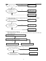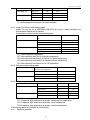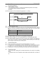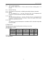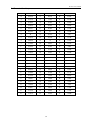
1
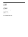
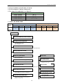
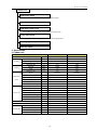
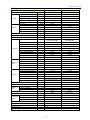
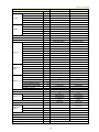
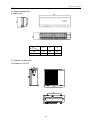
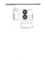
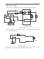
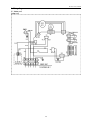
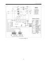
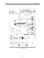
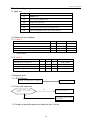
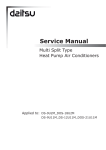
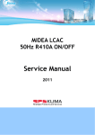
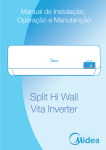
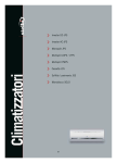
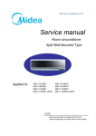
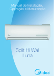
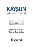
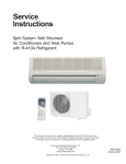
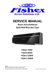
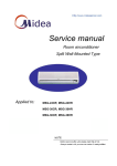
R series service manual
GD Midea Refrigeration Equipment Co. Ltd
MULTI SPLIT TYPE, HEAT PUMP AIR CONDITIONERS
Technical service manual 2007
R410a X series multi units
Indoor Models
MSXI-09HRN1
MSXI-12HRN1
Outdoor Models
M2OA-18HRN1
M2OA-21HRN1
M3OA-27HRN1
M3OA-30HRN1
214
R series service manual
Multi SERIES
1. Features
2. Function
3. Specification
4. Dimensions
5. Refrigeration cycle diagram
6. Wiring diagram
7. Troubleshooting
8. Electronic function
9. Characteristic of temp. sensor
215
R series service manual
1. Features
1.1 Universal outdoor unit and indoor unit design
1.2 R410a refrigerant; Cooling & heating units
1.3 The indoor unit combination is as follow list:
1.4
OUTDOOR UNIT MODEL
INDOOR UNIT COMBINATION
M2OA-18HRN1
M2OA-21HRN1
M3OA-27HRN1
M3OA-30HRN1
9K 2
9K+12K
9K 3
9K 2+12K
×
Working Temperature Range
×
×
Cooling
Models
Heating
Indoor Low
Indoor Hi
Outdoor Low
Outdoor Hi
17
/
5
43
multi
on/off
Indoor Low Indoor Hi Outdoor Low
/
30
-7
2.Function
Indoor unit
Operation ON/OFF by remote controller
Sensing by room temperature
Room temperature sensor.
Pipe temperature sensor.
Room temperature control
Maintain the room temperature in accordance with the setting temperature.
Starting temperature control
Indoor fan is delayed for 5 sec at the starting.
Turbo mode
Indoor fan speed control
high, med, low, breeze.
Anti-cold function
Operation indication Lamps (VLED)
Prevent the cold wind at
the beginning of unit start.
Light up in the VLED for each operation mode.
Defrost mode
Two-direction air vane
The unit will decide the louver direction according to operation mode.
Auto-restart function
Sleep mode auto control
The fan is turn to low speed (cooling/heating).
The unit will be turn off at the seventh hour.
Air flow Direction control
Independent dehumidification
The function will be
Self-diag.
function
operate in any
operation
The function is usually used in rainy days in
springtime or damp areas.
mode.
216
Outdoor Hi
24
R series service manual
Outdoor unit
Power relay control
The unit has 3 mins delay between continuously ON/OFF operations.
Check point
Hydrophilic aluminum fin
The hydrophilic fin can improve the heating efficiency at operation mode.
4 way valve control
It is only operated in the heating operation mode except defrosting operation.
Discharge pipe temperature protect
Anti-rust cabinet
3. Specification
3.1 Indoor unit
Model
Power supply
Cooling
Heating
MSXI-09HRN1
MSXI-12HRN1
Ph-V-Hz
1Ph, 220-240V~,50Hz
1PH, 220-240V~,50Hz
Capacity
Btu/h
9000
12000
Input
W
36.5
51.5
Rated current
A
0.17
0.24
Capacity
Btu/h
10000
13000
Input
W
37
51.5
Rated current
A
0.17
0.24
Model
RPG13H
RPG20D
Brand
Welling
Welling
Indoor fan
Input
W
33
38
motor
Capacitor
uF
1.2UF/450VAC
1.5UF/450V
1300/1200/1100/850
1270/1220/1050/950
1250/1100/880
1220/1050/950
Cooling Speed(turbo/hi/mi/lo)
Heating Speed(hi/mi/lo)
r/min
a.Number of rows
Indoor coil
b.Tube pitch(a)x row pitch(b)
mm
c.Fin spacing
mm
d.Fin type (code)
2
21x13.37
21x13.37
1.3
1.3
Hydrophilic aluminium
Hydrophilic aluminium
e.Tube outside dia.and type
mm
φ7 INNEGROOVE TUBE
φ7 INNEGROOVE TUBE
f.Coil length x height x width
mm
538x252x26.74
637x294x26.74
g.Number of circuits
Indoor air flow (Hi/Mi/Lo)
m3/h
Indoor noise level (Hi/Mi/Lo)
Indoor unit
2
2
2
480/440/320
650/570/490
dB(A)
39/37/29
41/36/34
Dimension (W*H*D)
mm
710x250x194
790x265x198
Packing
mm
800x340x270
875x375x285
(W*H*D)
Net/Gross weight
Kg
7.5/10
9/12
Liquid side/ Gas side
mm
Ф6.35/Ф9.53
Ф6.35/Ф12.7
217
R series service manual
3.2 Outdoor unit
Outdoor Model
Power supply
Capacity
Capacity
Cooling
Input
Rated current
EER
Capacity
Capacity
Heating
Input
Rated current
EER
Max. input power
Max. current
Starting current
Ph-V-Hz
Btu/h
W
W
A
w/w
Btu/h
W
W
A
w/w
W
A
A
Model
Type
Brand
Capacity
Compressor Input
Rated current(RLA)
Locked rotor Amp(LRA)
Thermal protector
Capacitor
Refrigerant oil
Model
Brand
Outdoor fan
Input
motor
Capacitor
Speed
a.Number of rows
b.Tube pitch(a)x row pitch(b)
c.Fin spacing
Outdoor coil d.Fin type (code)
e.Tube outside dia.and type
f.Coil length x height x width
g.Number of circuits
Outdoor air flow
Outdoor noise level
Dimension(W*H*D)
Outdoor
Packing (W*H*D)
unit
Net/Gross weight
Refrigerant type
Design pressure(Hi/Lo)
Liquid side/ Gas side
Refrigerant
Max. refrigerant pipe length
piping
Max. difference in level
Connection wiring
Plug type
Thermostat type
Operation temp
Ambient temp
M2OA-18HRN1
M2OA-21HRN1
1Ph,220-240V~,50Hz
18000
5275
1680
8.0
3.1
20000
5862
1680
8.0
3.45
2280
9.8
21.7
1Ph,220-240V~,50Hz
21000
6155
2000
9.7
3.04
24000
7034
2050
9.8
3.42
2520
12.0
21.7
PA108X1C-4FTDE ;
PA108X1C-4FTDE
PA108X1C-4FTDE ;
PA145X2C-4FT
ROTARY
GD TOSHIBA
8769 X 2
885X2
4.15X2
40X2
ROTARY
GD TOSHIBA
8769+12014
885+1200
4.15+5.6
40+57
Internal
25uF/370VAC X 2
350X2
YDK60-6
Welling
111
Internal
25+35uF/370VAC
350+480
YDK60-6
Welling
111
4uFx2
830/650
2
25.4x24
1.7
4uFx2
830/650
2
25.4x24
1.7
Hydrophilic aluminium
Hydrophilic aluminium
Ф9.53, Innergroove tube
810X610X44
Ф9.53, Innergroove tube
810X610X44
2/2
2200
2/2
2200
56
895X655X345
1050X780X470
76/82
980X2
4.4/2.0
Ф6.35/Ф9.53
15
10
56
895X655X345
1050X780X470
76/82
900+1100
4.4/2.0
Ф6.35/Ф9.53; Ф6.35/Ф12.7
15
10
Btu/h
W
A
A
uF
ml
W
uF
r/min
mm
mm
mm
mm
m3/h
dB(A)
mm
mm
Kg
R410A g
MPa
mm(inch)
m
m
℃
℃
No
No
Electronic control
17-30
18~43(cooling); -7~24(heating)
218
R series service manual
Outdoor Model
Power supply
Cooling
Ph-V-Hz
M3OA-27HRN1
M3OA-30HRN1
1Ph,220-240V~,50Hz
1Ph,220-240V~,50Hz
Capacity
Btu/h
27000
30000
Capacity
W
7913
8792
Input
W
2570
2880
Rated current
A
13.1
13.7
w/w
3.03
3.02
EER
Capacity
Btu/h
30000
34000
Capacity
W
8792
9965
Input
W
2700
3070
Rated current
A
w/w
13.3
3.22
14.2
3.22
Max. input power
W
3600
3600
Max. current
A
Starting current
A
Type
16.6
31.8
PA200X2CS-4KU1;
PA145X2C-4FT
ROTARY
16.6
31.8
PA200X2CS-4KU1;
PA145X2C-4FT
ROTARY
Brand
GD TOSHIBA
GD TOSHIBA
Heating
EER
Model
Capacity
Compressor
16791+12014
16791+12014
Input
Btu/h
W
1670+1200
1670+1200
Rated current(RLA)
A
7.81+5.6
7.81+5.6
Locked rotor Amp(LRA)
A
57+57
57+57
Capacitor
uF
Internal
45+35uF/370VAC
Internal
45+35uF/370VAC
Refrigerant oil
ml
Thermal protector
Model
Brand
Outdoor fan
motor
Welling
Welling
W
200
200
Capacitor
uF
4uFx2
4uFx2
r/min
1150
2
1150
2
b.Tube pitch(a)x row pitch(b)
mm
c.Fin spacing
mm
25.4x24
1.7
25.4x24
1.7
Hydrophilic aluminium
Hydrophilic aluminium
a.Number of rows
d.Fin type (code)
e.Tube outside dia.and type
mm
f.Coil length x height x width
mm
Ф9.53, Innergroove tube
813X812X44
Ф9.53, Innergroove tube
813X812X44
m3/h
3/3
3200
3/3
3200
g.Number of circuits
Outdoor air flow
Outdoor noise level
Outdoor unit
dB(A)
58
58
Dimension(W*H*D)
mm
860X830X330
860X830X330
Packing
mm
1000X985X425
1000X985X425
(W*H*D)
Net/Gross weight
Refrigerant type
Kg
R410A g
Design pressure(Hi/Lo)
Liquid side/ Gas side
Refrigerant
piping
750+480
YDK50-4G1
Input
Speed
Outdoor coil
750+480
YDK50-4G1
MPa
mm(inch)
Max. refrigerant pipe length
m
Max. difference in level
m
81/90
81/90
1550+1150
1550+1150
4.4/2.0
15
4.4/2.0
Ф6.35/Ф9.53;
Ф6.35/Ф12.7
15
10
10
Ф6.35/Ф9.53
Connection wiring
No
Plug type
No
Thermostat type
Electronic control
Operation temp
℃
17-30
Ambient temp
℃
18~43(cooling); -7~24(heating)
219
R series service manual
4 Dimension
4.1 Indoor unit dimension
a) Indoor unit 9
Dimension
Mode
W
H
D
9K
710
250
194
12K
790
265
198
4.2 Outdoor unit dimension
a) Outdoor unit 18K/21K
220
R series service manual
b) Outdoor unit 27K/30K
221
R series service manual
5. Refrigeration cycle diagram
“1 drives 3 system” is made up of one “1 drive 1 system” and one “1 drive 2 system”.
PMV1
PMV2
SV2
SV1
2
T2
#
1
#
T1
Compressor
refrigeration distributor
:
, :
:
1 drive 2 system
SV1 Primary four-way valve SV2 Secondary four-way valve
T1 T2 Indoor pipe temperature sensor
,
:
PMV1 PMV2 Electronic expansive valve
Condenser
Four-way valve
Evaporator
Compressor
:
1 drive 1 system
Notice For 1 drives 2 system, there are two individual refrigerant circuit and two compressors, but for the 1drive 2
system in the 1 drive 3 system, there is only one refrigerant circuit and only one compressor.
222
R series service manual
6. Wiring diagram
6.1 Indoor unit
Indoor unit
223
R series service manual
6.2 Outdoor unit
For 1 drive 2 outdoor unit
224
R series service manual
For 1 drive 3 outdoor unit
225
R series service manual
7. Troubleshooting
7.1 Indoor unit
Display
STATUS
E1
EEPROM error
E2
Zero-crossing examination error
E3
Fan speed beyond control
E4
Over current protection of the compressor occurs 4 times
E5
Open or short circuit of Room temperature sensor
E6
evaporator temperature sensor open or short circuit of
7.2 Outdoor unit (on mainboard)
7.2.1 1 drive 2
Failure phenomenon
Stand by
LED1
LED2
LED3
☆
☆
☆
☆
☆
High temp. protect of condenser
Temp. sensor in condenser 1
is open circuit or short circuit
Temp. sensor in condenser 2
is open circuit or short circuit
☆
☆
☆
Flash at 2Hz
7.2.2 1 drive 3
Failure phenomenon
LED1
LED2
LED3
Sensor in outdoor unit
☆
☆
RT3B or RT3A
High temp. protect of condenser
RT3A sensor is open circuit or short circuit
☆
RT3A
☆
RT4 sensor is open circuit or short circuit
☆
RT3B sensor is open circuit or short circuit
☆
RT4
RT3B
Flash at 2Hz
7.3 Diagnostic chart
7.3.1 EEPROM error
Circuit or software error on indoor
Replace indoor PCB
7.3.2 Cross zero signal error
Is power
connection
good?
supply
and
of connectors
NO
Be sure the power supply is good
and correct the connection
YES
Indoor PCB is defective. Replace
the indoor PCB.
7.2.3 Indoor fan speed has been out of control for over 1 minute
226
R series service manual
Is the indoor fan motor
connector and connection
good?
NO
Repair the
reconnect
YES
Indoor PCB is defective.
Replace the indoor PCB.
connector
and
YES
Is voltage being applied to
the fan motor?
(rang 90v-160v between mid
pin and N on CN1
NO
Replace the indoor fan motor
7.2.4 Indoor room temp. sensor or evaporator temp. sensor is open circuit or short circuit
Is the indoor fan motor
connector and connection
good?
NO
Repair the
reconnect
YES
Indoor PCB is defective.
Replace the indoor PCB.
connector
and
YES
Is voltage being applied to
the fan motor?
(rang 90v-160v between mid
pin and N on CN1
NO
Replace the indoor fan motor
7.2.5 High temp. Protect of condenser
When outdoor pipe temp. is more than 65°C, the unit will stop, and unit runs again when outdoor pipe
temp. less than 52°C.
Is the temp. more than 65°C ?
No
Is the temp sensor right according to the annex 1
Yes
No
Replace the outdoor main board
Replace the temp sensor
7.2.6 Temp. Sensor in condenser is open circuit or short circuit
Is the outdoor temperature
sensor
connector
and
connection good?
NO
Repair the
reconnect
connector
YES
Replace the sensor and
check if E5 display again?
YES
227
Replace outdoor e-box
and
R series service manual
8 Electronic functions
8.1
8.1.1
8.1.2
8.1.3
8.1.4
8.1.5
8.1.6
8.1.7
Electric Control working environment
Input voltage: 175~253V
Input power frequency: 50Hz/60Hz
Ambient temperature: -7°C~+43°C
Indoor fan normal working amp is less than 1A,
Outdoors fan normal working amp is less than 1.5A
Four-way valve normal working amp is less than 1A.
Swing motor: DC12V.
8.1.8
Display board
10.1 Display board
ON/OFF indicator
This indicator illuminates when the air conditioner is in operation.
PRE.-DEF. Indicator (For Cooling & Heating models only)
This indicator illuminates when the air conditioner starts defrosting automatically or when the warm air
control feature is activated in heating mode.
Auto Mode
This indicator illuminates when the air conditioner is in Auto Mode.
Turbo indicator
This indicator illuminates when the air conditioner is in turbo operation.
TEMPERATURE indicator
Usually it displays the temperature settings.
TIMER indicator
This indicator illuminates when TIMER is set ON/OFF.
FAN SPEED indicator
This indicator illuminates when change the fan speed.
Ionizer ( Plasma ) function indicator
This indicator illuminates when Ionizer ( Plasma ) function is on.
228
R series service manual
8.2 Proper symbols and their meanings
TA: Indoor ambient temperature
TE: Indoor evaporator temperature
TS: Setting temperature through the remote controller
TE1: Anti-cold wind, from Fan Off to Breeze temperature
TE2: Anti-cold wind, from Breeze to Setting Fan Speed temperature
TE3: Anti-cold wind, from Setting Fan Speed to Breeze temperature
TE4: Anti-cold wind, from Breeze to Fan Off temperature
TE5: Evaporator low temperature protection entering temperature
TE6: Evaporator low temperature protection restoring temperature
TE7: Evaporator high temperature protection, compressor off temperature
TE8: Evaporator high temperature protection, fan off temperature
TE9: Evaporator high temperature protection, restoring temperature
T3: Outdoor unit pipe sensor
T4: Outdoors temperature sensor
8.3 Systematic functions.
Remote receiving.
Testing and forced run.
Position set for indoor unit wind vane.
LED display and alarm.
On or off Timer.
Protection for the compressor.
High temperature protection of indoor heat exchanger in heating mode.
Auto defrosting and heating recovery under heating mode.
Anti cold air under heating mode.
Anti frozen under cooling mode.
8.4 Protection
8.4.1 The compressor functions protection with a delay of three minutes.
8.4.2 High temp. protection of condenser.
8.4.3 Sensor protection at open circuit and breaking disconnection
8.4.4 Temperature Fuse break protection
8.4.5 Fan Speed is out of control. When Indoor Fan Speed is too high(higher than High
Fan+300RPM)or too low(lower than 400RPM), the entire unit stops and LED displays failure
information and can’t returns to normal operation automatically.
8.5 Fan-only mode
Fan speed is high/mid/low/ Auto
8.6 Cooling mode
The 4-way valve is closed under cooling mode.
The action of the compressor and the outdoor fan:
Condition
Compressor
On
Outdoor fan
Temp. up
TA> Ts+1
TA<Ts+1
Off
Off
Temp. down
TA> Ts
On
On
TA<Ts
Off
Off
TA: Indoor ambient temperature
229
On
R series service manual
TS: Setting temperature through the remote controller
Auto fan under cooling mode:
Condition
Indoor fan speed
T=Indoor Temp.-Setting Temp.
Temp. up
Temp. down
T<3℃
Low
3℃<T<5℃
Med.
T>5℃
High
T> 3℃
High
1℃<T<3℃
Med.
T<1℃
Low
Anti-freezing control to indoor evaporator under cooling mode
Condition
Temp.
Temp. up
T> TE6
T< TE6
Temp. down
Compressor
On
>5 Minutes
T> TE5
T< TE5
Outdoor fan
Time
>5 Minutes
On
Off
Off
On
On
Off
Off
Condenser high-temperature protection under heating mode
T3 >65℃,turn off compressor.
TE5: Evaporator low temperature protection entering temperature
TE6: Evaporator low temperature protection restoring temperature
8.7
Dehumidifying mode
8.7.1 The 4-way valve is off in dehumidifying mode
8.7.2 Compressor and Indoor Fan actions in dehumidifying mode
Compressor run 5 minutes, and indoor fan run 5 minutes in low speed, then turn off the
compressor, indoor fan run 5 minutes in low speed. And repeat on and off cycle.
8.7.3 Low room temperature protection:
When room temperature decreases to below 10℃, the compressor and the outdoor fan
will stop(indoor fan is Breeze). Dehumidifying operation will be resumed when room
temperature restores to over 13℃.
8.7.4 Under dehumidifying mode, the anti-freezing function of the indoor heat exchanger is the
same as that of cooling mode.
8.8
Heating mode
8.8.1 Generally, the 4-way valve is open in heating mode, but it is closed in defrosting mode.
4-way valve must delay 2 minutes compared with compressor if the compressor changed
into non-heating mode or turned off. 4-way valve doesn't delay in dehumidifying mode.
8.8.2 Generally, the outdoors fan is turned off with the on-off action of compressor in heating
mode, except for the defrosting mode or the end of defrosts.
8.8.3 Action conditions of compressor under heating mode: compressor must run for 7
minutes after starting and then judge temperature. Meanwhile other protections are still
valid.
230
R series service manual
Condition
Room temp. up
Room temp. down
Compressor
Outdoor fan
TA> Ts+3
Off
Off
TA<Ts+3
On
On
TA< Ts+2
On
On
TA>Ts+2
Off
Off
TA: Indoor ambient temperature
TS: Setting temperature through the remote controller
8.8.4 Indoor Fan actions under heating mode
Indoor Fan can be set at HIGH/MID/LOW/AUTO by using a remote controller, but
Anti-cold wind function has the priority.
Anti-cold wind control function under heating mode
Condition
Indoor fan speed
TE
Indoor exchanger temp. up
Indoor exchanger temp. down
TE<TE1
Off
TE1<TE<TE2
Breeze
TE>TE2
Setting fan speed
TE> TE3
Setting fan speed
TE3<TE<TE4
Breeze
TE<TE4
Off
TE: Indoor evaporator temperature
TE1: Anti-cold wind, from Fan Off to Breeze temperature
TE2: Anti-cold wind, from Breeze to Setting Fan Speed temperature
TE3: Anti-cold wind, from Setting Fan Speed to Breeze temperature
TE4: Anti-cold wind, from Breeze to Fan Off temperature
8.8.5 Auto wind under heating mode
Condition
Indoor fan speed
T=Indoor Temp.-Setting Temp.
Room temp. up
Room temp. down
T<2℃
High
T>2℃
Med.
T> 0℃
Med.
T<0℃
High
8.8.6 Indoor evaporator high-temperature protection under heating mode
Indoor exchanger temp. up
Indoor exchanger temp. down
Condition
Compressor
Outdoor fan
TE<TE8
On
On
TE8<TE<TE7
On
Off
TE>TE7
Off
Off
TE>TE9
Off
Off
TE<TE9
On
On
TE: Indoor evaporator temperature
TE7: Evaporator high temperature protection, compressor off temperature
TE8: Evaporator high temperature protection, fan off temperature
TE9: Evaporator high temperature protection, restoring temperature
8.9 Defrosting operation (Available for heating only).
8.9.1 Defrosting condition:
231
R series service manual
When T3<0℃ and compressor runs 40 minutes.
T3: Temp. of condenser.
8.9.2 Ending condition of defrost
If one of following conditions is satisfied, end the defrosting and turn into heating:
A.The defrost time has reached to 10 minutes.
B.T3>20. ℃
8.10.3 Time sequence of the whole defrosting procedure is as follows
Compressor
ON
4-way Valve
ON
OFF
Outdoor Fan
ON
OFF
8.10
Automatic operation mode
8.10.1 The air conditioner automatically selects one of the following operation modes: cooling,
heating or ventilation according to the difference between room temp. (TA) and set temp.
(TS).
TA—TS
Operation mode
TA—TS>2℃
Cooling
-1℃≤TA—TS≤+2℃
Fan-only
TA—TS<-1℃
Heating (Fan-only for cooling only type)
8.10.2 The indoor fan blows automatically in corresponding selected mode.
8.10.3 The motion of indoor fan’s vane should accord with the selected operation mode.
8.10.4 One mode should be carried out for at least 15 minutes once selected. If the compressor
cannot start for 15 minutes, reselect the operation mode according to the room temp.
and set temp.or reselect when the set temp. varies.
8.11
Forced cooling function
8.11.1 Select forced cooling function with the forced cooling button or the switch.
8.11.2 The compressor is unconditionally turned on, after 30 minutes cooling operation whose
fan mode is set as low; the A/C operates under the DRY mode with a set temp. of 24℃.
8.11.3 All protections of remote control cooling are available under forced cooling operation.
8.12
Forced Auto function
Select forced auto function with the forced auto button or the switch in the display
board.
In forced auto status the A/C operates under remote control mode with a set temp. of
24℃.
232
R series service manual
8.13
Timer Function Requirement
The maximum length of timer is 24 hours and the minimum resolving power is 15
minutes.
8.14
Economic Running
8.14.1 The economic running function is available under cooling, heating or auto mode.
8.14.2 Cooling:
The set temperature rise 1℃ per hour. Two hours later, the set temperature will
maintain as a constant and the air circulation is kept at low speed.
8.14.3 Heating:
The set temperature decrease 1℃ per hour. Two hours later, the set temperature will
maintain as a constant and the air circulation is kept at low speed (Cold air proof
function takes precedence over all).
8.14.4 Auto:
The economic running function operates in accordance with the selected running mode
by the auto mode.
8.15 Mode conflict
The indoor units can not work cooling mode and heating at same time.
Heating mode has a priority.
8.16.1Definition
Cooling mode
Heating Mode
Fan
Cooling mode
No
Yes
No
Heating Mode
Yes
No
Yes
Fan
No
Yes
No
Off
No
No
No
No: No mode conflict;
Yes: Mode conflict
233
Off
No
No
No
No
R series service manual
9 Characteristic of temp. sensor
Temp.℃
Resistance KΩ
Temp.℃
Resistance KΩ
Temp.℃
Resistance KΩ
-10
62.2756
17
14.6181
44
4.3874
-9
58.7079
18
13.918
45
4.2126
-8
56.3694
19
13.2631
46
4.0459
-7
52.2438
20
12.6431
47
3.8867
-6
49.3161
21
12.0561
48
3.7348
-5
46.5725
22
11.5
49
3.5896
-4
44
23
10.9731
50
3.451
-3
41.5878
24
10.4736
51
3.3185
-2
39.8239
25
10
52
3.1918
-1
37.1988
26
9.5507
53
3.0707
0
35.2024
27
9.1245
54
2.959
1
33.3269
28
8.7198
55
2.8442
2
31.5635
29
8.3357
56
2.7382
3
29.9058
30
7.9708
57
2.6368
4
28.3459
31
7.6241
58
2.5397
5
26.8778
32
7.2946
59
2.4468
6
25.4954
33
6.9814
60
2.3577
7
24.1932
34
6.6835
61
2.2725
8
22.5662
35
6.4002
62
2.1907
9
21.8094
36
6.1306
63
2.1124
10
20.7184
37
5.8736
64
2.0373
11
19.6891
38
5.6296
65
1.9653
12
18.7177
39
5.3969
66
1.8963
13
17.8005
40
5.1752
67
1.830
14
16.9341
41
4.9639
68
1.7665
15
16.1156
42
4.7625
69
1.7055
16
15.3418
43
4.5705
70
1.6469
234