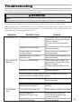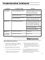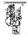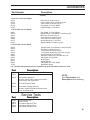
1
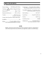
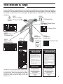
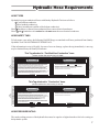
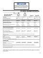
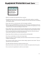
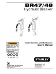
BR45
Hydraulic Breaker
Safety, Operation, and Maintenance
SERIOUS INJURY OR DEATH
COULD RESULT FROM THE
I M P R O P E R R E PA I R O R
SERVICE OF THIS TOOL.
Service Manual
REPAIRS AND/OR SERVICE TO
THIS TOOL MUST ONLY BE
DONE BY AN AUTHORIZED AND
CERTIFIED DEALER.
Read
The
Manual
Wear
Wear
Hearing
Breathing
Protection
Protection
Wear
Eye
Protection
STANLEY
Stanley Hydraulic Tools
Copyright c 2004 The Stanley Works
OPS/Service & CE Version USA
07650 02/04 Ver. 2
3810 SE Naef Road
Milwaukie, OR 97267-5698 USA
Phone: (503) 659-5660
Fax: (503) 652-1780
Table of Contents
BR45
Hydraulic Breaker
Servicing The
BR45 Hydraulic Breaker:
This manual contains Safety,
Operation, Service and
Troubleshooting information.
Stanley Hydraulic Tools
recommends that servicing of
hydraulic tools, other than
routine maintenance, must be
performed by an authorized and
certified dealer. Please read the
WARNING on the cover and the
SAFETY warning below.
Contents
1
Certificate of Conformity (BR45)
2
Specifications
3
General Safety Instructions
4,5
Tools Decals and Tags
6
Hydraulic Hose Requirements
7
HTMA Requirements
8
Equipment Protection and Care
9
10
Operating Instructions
Copyright c 2004 The Stanley Works
All rights reserved.
Under copyright law, this document may
not be copied in whole or in part without
the prior written consent of The Stanley
Works. This exception does not permit
copies to be made for others, whether or
not sold. Under the law, copying includes
translating into another language, format
or medium. This copyright notice must
appear on any permitted copies.
Service
11-13
Troubleshooting
14,15
Maintenance
16,17
Parts Illustration
19,21
Parts List
18,20
Accessories
22
Warranty
23
SAFETY FIRST
It is the responsibility of the operator and
service technician to read rules and
instructions for safe and proper operation and
maintenance.
A cautious worker using common sense is the
greatest safety device.
1
CERTIFICATE OF CONFORMITY
Hydraulic Tools
I, the undersigned:
Winterling, David
Surname and First names
Hereby certify that the construction plant or equipment specified hereunder:
1. Manufacturer: Stanley Hydraulic Tools, 3810 SE Naef Road, Milwaukie, Oregon USA
2. Representative in the Union: Stanley Svenska AB, Box 9054, 400 92 GÖteborg, SWEDEN
3. Category: Hydraulic Hand Held Concrete Breaker
4. Make: Stanley Hydraulic Tools
5. Type: BR4514801 / BR4516201 / BR4516801 / BR4512201E
6. Type serial number of equipment: ALL
7. Year of Manufacture: Beginning 2002
Has been manufactured in conformity with the provisions of the Machinery Directive 98/37/EC
Harmonized standard applied:
EN 792-4
We also declare that it meets the specification of Noise Directive 2000/14/EC, measured in
accordance to the Conformity Evaluation Method set out in Annex VI para. 5 and evaluated
during production as in Annex VI para. 6, 2nd procedure.
8. Noise related value: 23 kg
9. Measured sound power on equipment representative of this type: 106 LwA
10. Guaranteed sound power level for this equipment: 109 LwA
11. Notified body for EC directive 2000/14/EC: 0404
SMP Svensk Maskinprovning AB
Fyrisborgsgatan 3
754 50 Uppsala, SWEDEN
12. Special Provisions: None
Issued at Stanley Hydraulic Tools, Milwaukie, Oregon USA
Date: 8/21/02
Signature:
Position: Engineering Manager
P/N 52571 Rev.1, 8/21/02
2
Specifications
Pressure Range............1500- 2000 psi/105-140 bar
FlowRange
(HTMA-II) 7-9gpm/26-34lpm
OverallLength.....(T-Handle23.5/25.5in.60/65cm.
......(Anti-VibrationHandle)25.2/28.25in.65/72cm
OptimumFlow..................................8gpm / 30 lpm
OverallWidth-@handles..(T-Handle)14in./35cm
.....................(Anti-VibrationHandle)17.5/44.5cm
Maximum BackPressure.................250 Psi/17bar
Max.FluidTemp...................................140°F/60°C
Couplers.................................... HTMA Flush Face
SystemType......................OpenOrClosedCenter
PerNFPAT3.20.15/ISO16028
Connect Size & Type-3/8 in. MalePipeHoseEnds
HoseWhips.........................................................Yes
Weight......................(T-Handle) 45/48 lbs.20/21kg
.............(Anti-VibrationHandle)48/51lbs.22/23 kg
PortSize.............................................SAE8O-ring
SoundPowerLevel....................................109dBA
VibrationLevel.....................(T-Handle)13.5m/sec²
.........................(Anti-VibrationHandle)10.1m/sec²
NOTE
Weights, dimensionsandoperatingspecificationslistedare subject to changewithout
notice.Wherespecificationsarecriticalto your application, please consult the factory.
3
SAFETY SYMBOLS
Safety symbols and signal words, as shown below, are used to emphasize all operator, maintenance
and repair actions which, if not strictly followed, could result in a life-threatening situation, bodily injury
or damage to equipment.
This is the safety alert symbol. It is used to alert you to potential personal
injury hazards. Obey all safety messages that follow this symbol to avoid
possible injury or death.
This safety alert and signal word indicate an imminently hazardous
situation which, if not avoided, will result in death or serious injury.
This safety alert and signal word indicate a potentially hazardous
situation which, if not avoided, could result in death or serious injury.
This safety alert and signal word indicate a potentially hazardous situation
which, if not avoided, may result in minor or moderate injury.
This signal word indicates a potentially hazardous situation which, if not
avoided, may result in property damage.
This signal word indicates a situation which, if not avoided, will result in
damage to the equipment.
This signal word indicates a situation which, if not avoided, may result in
damage to the equipment.
Always observe safety symbols. They are included for your safety and for the protection of the tool.
LOCAL SAFETY REGULATIONS
Enter any local safety regulations here. Keep these instructions in an area accessible
to the operator and maintenance personnel.
4
General Safety Instructions
Tool operators and maintenance personnel must always comply with the safety precautions
given in this manual and on the stickers and tags attached to the tool and hose.
These safety precautions are given for your safety. Review them carefully before operating
the tool and before performing general maintenance or repairs.
Supervising personnel should develop additional precautions relating to the specific work
area and local safety regulations. If so, place the added precautions in the space provided
on page 4.
This tool will provide safe and dependable service if operated in accordance with the instructions
given in this manual. Read and understand this manual and any stickers and tags attached to the
tool and hoses before operation. Failure to do so could result in personal injury or equipment
damage.
A
Operator must start in a work area without bystanders. Flying debris can cause serious injury. The operator
must be familiar with all prohibited work areas such as excessive slopes and dangerous terrain conditions.
A
Establish a training program for all operators to ensure safe operations.
A
Do not operate the tool unless thoroughly trained or under the supervision of an instructor.
A
Always wear safety equipment such as goggles, head protection, and safety shoes at all times when operating
the tool.
A
Do not inspect or clean the tool while the hydraulic power source is connected. Accidental engagement of the
tool can cause serious injury.
A
Do not operate this tool without first reading the Operating Instructions.
A
Do not install or remove Parts on this tool while the hydraulic power source is connected. Accidental
engagement of the tool can cause serious injury.
A
Never operate the tool if you cannot be sure that underground utilities are not present. Underground electrical
utilities present an electrocution hazard. Underground gas utilities present an explosion hazard. Other
underground utilities may present other hazards.
A
Do not wear loose fitting clothing when operating the tool. Loose fitting clothing can get entangled with the
tool and cause serious injury.
A
Supply hoses must have a minimum working pressure rating of 2500 psi/175 bar.
A
Be sure all hose connections are tight.
A
The hydraulic circuit control valve must be in the “OFF” position when coupling or uncoupling the tool. Wipe
all couplers clean before connecting. Failure to do so may result in damage to the quick couplers and cause
overheating. Use only lint-free cloths.
A
Do not operate the tool at oil temperatures above 140° F/60° C. Operation at higher oil temperatures can
cause operator discomfort and may cause damage to the tool.
A
Do not operate a damaged, improperly adjusted, or incompletely assembled tool.
A
To avoid personal injury or equipment damage, all tool repair, maintenance and service must only be
performed by authorized and properly trained personnel.
A
Do not exceed the rated limits of the tool or use the tool for applications beyond its design capacity.
A
Always keep critical tool markings, such as labels and warning stickers legible.
A
Always replace parts with replacement parts recommended by Stanley Hydraulic Tools.
A
Check fastener tightness often and before each use daily.
5
Tool Decals & Tags
A Name Tag Sticker is attached to the tool. Never exceed the flow and pressure levels specified on
this sticker. The information listed on the Name Tag sticker must be legible at all times. Replace
this sticker if it becomes worn or damaged. A replacement is available from your local Stanley
distributor.
28322
11207
CE Label
Circuit “D” Label
CE Models Only
CE Models Only
58603
Guaranteed Sound Power
Level Sticker
CE Models Only
28379
Stanley Label
CE Models Only
07487
Name Tag
6"
CE Models Only
✘
28376
Stanley Label
CE Models Only
28409
Composite
Safety Label
11208
Hex Shank
Length Label
✔
6¼"
DANGER
DANGER
1. FA I LU R E T O U S E H Y D RAU L I C H O S E L A B E L E D A N D
CERTI-FIED AS NON-CONDUCTIVE WHEN USING
HYDRAULIC TOOLS ON OR NEAR ELECTRICAL LINES
MAY RESULT IN DEATH OR SERIOUS INJURY.
BEFORE USING HOSE LABELED AND CERTIFIED AS
NON- CONDUCTIVE ON OR NEAR ELECTRIC LINES.
BE SURE THE HOSE IS MAINTAINED AS NON- CONDUCTIVE . THE
HOSE SHOULD BE REGULARLY TESTED FOR ELECTRIC CURRENT
LEAKAGE IN ACCORDANCE WITH YOUR SAFETY DEPARTMENT
INSTRUCTIONS.
2. A H Y D R A U L I C L E A K O R B U R S T M AY C A U S E O I L
INJECTION INTO THE BODY OR CAUSE OTHER SEVERE PERSONAL
INJURY.
A. D O N O T E X C E E D S P E C I F I E D F L O W A N D
P R E S S U R E F O R T H I S T O O L . E X C E S S F LO W O R
PRESSURE MAY CAUSE A LEAK OR BURST.
B. D O N O T E X C E E D R AT E D W O R K I N G P R E S S U R E
OF HYDRAULIC HOSE USED WITH THIS TOOL.
E X C E S S P R E S S U R E M AY C A U S E A L E A K O R
BURST.
C. C H E C K T O O L , H O S E , C O U P L E R S &
C O N N E C T O R S
D A I LY
F O R
LEAKS. DO NOT FEEL FOR LEAKS WITH
Y O U R H A N D S . C O N TA C T W I T H A L E A K M AY
RESULT IN SEVERE PERSONAL INJURY.
The SAFETY TAG, P/N 15875, shown at right, smaller
than actual size, is attached to the tool when shipped
from the factory. Read and understand the safety
instructions listed on this tag before removal. We
suggest you retain this tag and attach it to the tool
when not in use.
D. DO NOT LIFT OR CARRY TOOL BY THE HOSES. DO NOT ABUSE
HOSE. DO NOT USE KINKED, TORN OR DAMAGED HOSES.
3. M A K E S U R E H Y D R A U L I C H O S E S A R E P R O P E R LY
CONN-ECTED TO THE TOOL BEFORE PRESSURIZING
S Y S T E M . S Y S T E M P R E S S U R E H O S E M U S T A LWAY S
B E C O N N E C T E D T O T O O L “ I N ” P O R T. S Y S T E M
R E T U R N H O S E M U S T A LW AY S B E C O N N E C T E D AT
T O O L “ O U T ” P O RT. R E V E R S I N G C O N N E C T I O N S M AY
C A U S E R E V E R S E T O O L O P E R AT I O N W H I C H C A N
CAUSE SEVERE PERSONAL INJURY.
4. D O N O T C O N N E C T C L O S E D - C E N T E R T O O L S T O
O P E N - C E N T E R H Y D R A U L I C S Y S T E M S . T H I S M AY
C A U S E E X T R E M E S Y S T E M H E AT A N D / O R S E V E R E
PERSONAL INJURY.
DO NOT CONNECT OPEN-CENTER TOOLS TO C LO S E D - C E N T E R
HYDRAULIC SYSTEMS. THIS MAY RESULT IN LOSS OF OTHER
HYDRAULIC FUNCTIONS POWERED BY THE SAME SYSTEM AND/OR
SEVERE PERSONAL INJURY.
5. B Y S TA N D E R S M A Y B E I N J U R E D I N Y O U R W O R K
A R E A . K E E P BY S TA N D E R S C L E A R O F YO U R W O R K
AREA.
6. WEAR HEARING, EYE, FOOT, HAND AND HEAD PROTECTION.
7. TO AVOID PERSONAL INJURY OR EQUIPMENT DAMAGE, ALL TOOL
REPAIR, MAINTENANCE AND
SERVICE MUST BE
PERFORMED BY AUTHORIZED
A N D P R O P E R LY
TRAINED PERSONNEL.
IMPORTANT
IMPORTANT
READ OPERATION MANUAL AND
SAFETY INSTRUCTIONS FOR THIS
TOOL BEFORE USING IT.
READ OPERATION MANUAL AND
SAFETY INSTRUCTIONS FOR THIS
TOOL BEFORE USING IT.
USE ONLY PARTS AND REPAIR
PROCEDURES APPROVED BY
STANLEY AND DESCRIBED IN THE
OPERATION MANUAL.
USE ONLY PARTS AND REPAIR
PROCEDURES APPROVED BY
STANLEY AND DESCRIBED IN THE
OPERATION MANUAL.
TAG TO BE REMOVED ONLY BY TOOL
OPERATOR.
(517)
SEE OTHER SIDE
15875
TAG TO BE REMOVED ONLY BY TOOL
OPERATOR.
(517)
SEE OTHER SIDE
15875
6
Hydraulic Hose Requirements
HOSE TYPES
Hydraulic hose types authorized for use with Stanley Hydraulic Tools are as follows:
Certified non-conductive
Wire-braided (conductive)
Fabric-braided (not certified or labeled non-conductive)
Hose listed above is the only hose authorized for use near electrical conductors.
Hoses and listed above are conductive and must never be near electrical conductors.
HOSE SAFETY TAGS
To help ensure your safety, the following DANGER tags are attached to all hoses purchased from Stanley
Hydraulic Tools. DO NOT REMOVE THESE TAGS.
If the information in a tag is illegible because of wear or damage, replace the tag immediately. A new tag
may be obtained from your Stanley Distributor.
This Tag attached to “Certified Non-Conductive” hose.
DANGER
1. FAILURE TO USE HYDRAULIC HOSE LABELED AND CERTIFIED AS NON-CONDUCTIVE WHEN USING
HYDRAULIC TOOLS ON OR NEAR ELECTRIC LINES MAY RESULT IN DEATH OR SERIOUS INJURY.
FOR PROPER AND SAFE OPERATION, MAKE SURE THAT YOU HAVE BEEN PROPERLY TRAINED IN
CORRECT PROCEDURES REQUIRED FOR WORK ON OR AROUND ELECTRIC LINES.
2. BEFORE USING HYDRAULIC HOSE LABELED AND CERTIFIED AS NON-CONDUCTIVE ON OR NEAR
ELECTRIC LINES, WIPE THE ENTIRE LENGTH OF THE HOSE AND FITTINGS WITH A CLEAN,
DRY, ABSORBENT CLOTH TO REMOVE DIRT AND MOISTURE AND TEST HOSE FOR MAXIMUM
ALLOWABLE CURRENT LEAKAGE IN ACCORDANCE WITH SAFETY DEPARTMENT INSTRUCTIONS.
DANGER
4. HANDLE AND ROUTE HOSE CAREFULLY TO AVOID KINKING, ABRASION, CUTTING OR CONTACT
WITH HIGH TEMPERATURE SURFACES. DO NOT USE IF KINKED. DO NOT USE HOSE TO PULL OR
LIFT TOOLS, POWER UNITS, ETC.
5. CHECK ENTIRE HOSE FOR CUTS, CRACKS, LEAKS, ABRASIONS, BULGES OR DAMAGE TO
COUPLINGS. IF ANY OF THESE CONDITIONS EXIST, REPLACE THE HOSE IMMEDIATELY.
NEVER USE TAPE OR ANY DEVICE TO ATTEMPT TO MEND THE HOSE.
6.
AFTER EACH USE, STORE IN A CLEAN, DRY AREA.
3. DO NOT EXCEED HOSE WORKING PRESSURE OR ABUSE HOSE. IMPROPER USE OR HANDLING OF
HOSE COULD RESULT IN BURST OR OTHER HOSE FAILURE. KEEP HOSE AS FAR AWAY AS
POSSIBLE FROM BODY AND DO NOT PERMIT DIRECT CONTACT DURING USE. CONTACT AT THE
BURST CAN CAUSE BODILY INJECTION AND SEVERE PERSONAL INJURY.
SEE OTHER SIDE
SEE OTHER SIDE
Side 1
Side 2
DO NOT REMOVE THIS TAG
DO NOT REMOVE THIS TAG
(shown smaller than actual size) p/n 27987
This Tag attached to “Conductive” hose.
DANGER
DANGER
1. DO NOT USE THIS HYDRAULIC HOSE ON OR NEAR ELECTRIC LINES. THIS HOSE IS NOT
LABELED OR CERTIFIED AS NON-CONDUCTIVE. USING THIS HOSE ON OR NEAR ELECTRIC LINES
MAY RESULT IN DEATH OR SERIOUS INJURY.
5. CHECK ENTIRE HOSE FOR CUTS, CRACKS, LEAKS, ABRASIONS, BULGES OR DAMAGE TO
COUPLINGS. IF ANY OF THESE CONDITIONS EXIST, REPLACE THE HOSE IMMEDIATELY.
NEVER USE TAPE OR ANY DEVICE TO ATTEMPT TO MEND THE HOSE.
2. FOR PROPER AND SAFE OPERATION, MAKE SURE THAT YOU HAVE BEEN PROPERLY TRAINED IN
CORRECT PROCEDURES REQUIRED FOR WORK ON OR AROUND ELECTRIC LINES.
6.
AFTER EACH USE, STORE IN A CLEAN, DRY AREA.
3. DO NOT EXCEED HOSE WORKING PRESSURE OR ABUSE HOSE. IMPROPER USE OR HANDLING OF
HOSE COULD RESULT IN BURST OR OTHER HOSE FAILURE. KEEP HOSE AS FAR AWAY AS
POSSIBLE FROM BODY AND DO NOT PERMIT CONTACT DURING USE. CONTACT AT THE
BURST CAN CAUSE BODILY INJECTION AND SEVERE PERSONAL INJURY.
4. HANDLE AND ROUTE HOSE CAREFULLY TO AVOID KINKING, ABRASION, CUTTING OR CONTACT
WITH HIGH TEMPERATURE SURFACES. DO NOT USE IF KINKED. DO NOT USE HOSE TO PULL OR
LIFT TOOLS, POWER UNITS, ETC.
SEE OTHER SIDE
SEE OTHER SIDE
Side 1
Side 2
DO NOT REMOVE THIS TAG
DO NOT REMOVE THIS TAG
(shown smaller than actual size) p/n 29144
HOSE PRESSURE RATING
The rated working pressure of the hydraulic hose must be equal to or higher than the relief valve setting on
the hydraulic system.
7
These are general hydraulic system
requirements. See tool specifications
page for tool specific requirements.
HTMA Requirements
Hydraulic System
Requirements
Tool
Category:
20Lpm at 138bar
BHTMA CATEGORY
30Lpm at 138bar
BHTMA CATEGORY
Type I
Type RR
Type III
Type II
Flow rate
Tool Operating Pressure
4-6 GPM (15-23
7-9 GPM (26-34
11-13 GPM
lpm)
Lpm)
lpm)
(at the power supply outlet)
2000 psi (138 bar) 2000 psi (138 bar) 2000 psi (138 bar)
2000 psi (138 bar)
System relief valve setting
(at the power supply outlet)
Maximum back pressure
(at tool end of the return hose)
Measured at a max. fluid viscosity of:
(at min. operating temperature)
Temperature
Sufficient heat rejection capacity
to limit max. fluid temperature to:
(42-49
9-10.5 GPM
(34-40
lpm)
2100-2250
2100-2250
2100-2250
2200-2300
(145-155 bar)
(145-155 bar)
(145-155 bar)
(152-159 bar)
250 psi
250 psi
250 psi
250 psi
(17 bar)
(17 bar)
(17 bar)
(17 bar)
400 SSU
400 SSU
400 SSU
400 SSU
(82 centistokes)
(82 centistokes)
(82 centistokes)
(82 centistokes)
140° F (60° C)
140° F (60° C)
140° F (60° C)
140° F (60° C)
3 hp (2.24 kW)
40° F (22° C)
5 hp (3.73 kW)
40° F (22° C)
7 hp (5.22 kW)
40° F (22° C)
6 hp (4.5 kW)
40° F (22° C)
(at max. expected ambient temperature)
Min. cooling capacity
at a temperature difference of
between ambient and fluid temps
NOTE: Do not operate the tool at oil temperatures above 140 ° F (60° C). Operation at higher temperatures can cause operator
discomfort at the tool.
Filter
Min. full-flow filtration
sized for flow of at least:
25 microns
25 microns
25 microns
30 GPM (114 lpm)
30
GPM
(114
lpm)
30 GPM (114 lpm)
25 microns
30 GPM (114 lpm)
(For cold temp. startup and max. dirt-holding capacity)
Hydraulic fluid
Petroleum based
(premium grade, anti-wear, non-conductive)
Viscosity
(at min. and max. operating temps)
100-400 SSU*
100-400 SSU*
100-400 SSU*
100-400 SSU*
(20-82 centistokes)
(20-82 centistokes)
(20-82 centistokes)
(20-82 centistokes)
NOTE: When choosing hydraulic fluid, the expected oil temperature extremes that will be experienced in service determine the
most suitable temperature viscosity characteristics. Hydraulic fluids with a viscosity index over 140 will meet the requirements over
a wide range of operating temperatures.
*SSU = Saybolt Seconds Universal
NOTE: These are general hydraulic system requirements. See tool Specification page for tool specific
requirements.
8
Equipment Protection and Care
In addition to the Safety
Precautions found in this
manual, observe the
following for equipment
protection and care.
• Make sure all couplers are wiped clean before connection.
• The hydraulic circuit control valve must be in the “OFF” position when coupling or uncoupling
hydraulic tools. Failure to do so may result in damage to the quick couples and cause overheating
of the hydraulic system.
• Always store the tool in a clean dry space, safe from damage or pilferage.
• Make sure the circuit PRESSURE hose (with male quick disconnect) is connected to the “IN” port.
The circuit RETURN hose (with female quick disconnect) is connected to the opposite port. Do not
reverse circuit flow. This can cause damage to internal seals.
• Always replace hoses, couplings and other parts with replacement parts recommended by Stanley
Hydraulic Tools. Supply hoses must have a minimum working pressure rating of 2500 psi/172 bar.
• Do not exceed the rated flow (see Specifications page) in this manual for correct flow rate and
model number. Rapid failure of the internal seals may result.
• Always keep critical tool markings, such as warning stickers and tags legible.
• Do not force a small breaker to do the job of a large breaker.
• Keep tool bit sharp for maximum breaker performance. Make sure that tool bits are not chipped or
rounded on the striking end.
• Never operate a breaker without a tool bit or without holding it against the work surface. This puts
excessive strain on the breaker foot.
• Tool repair should be performed by experienced personnel only.
• Make certain that the recommended relief valves are installed in the pressure side of the system.
• Do not use the tool for applications for which it was not intended.
9
Operating Instructions
The recommended hose size is .500 inch/12 mm I.D.
up to 50 ft/15 m long and .625 inch/16 mm I.D.
minimum up to 100 ft/30 m.
Pre-Operation Procedures
Check Power Source
1. Using a calibrated flowmeter and pressure gauge,
check that the hydraulic power source develops a
flow of 7-9 gpm/26-34 lpm at 1500/2000 psi/105140 bar. 5-6 gpm /18-22 lpm at 1500-2000 psi
/105-140 bar.
2. Make certain the hydraulic power source is
equipped with a relief valve set to open at 2250
psi/155 bar maximum.
Install Tool Bit
1. Rotate the latch on the breaker foot downward
(pointing away from the tool).
2. Insert the tool bit into the foot and pull the latch up
to lock the tool bit in place.
Connect Hoses
1. Wipe all hose couplers with a clean, lint-free cloth
before making connections.
2. Connect the hoses from the hydraulic power
source to the tool fittings or quick disconnects. It
is a good practice to connect return hoses first and
disconnect them last to minimize or avoid trapped
pressure within the tool.
3. Observe flow indicators stamped on hose couplers
to ensure that fluid flow is in the proper direction.
The female coupler on the tool hose is the inlet
coupler.
4. Move the hydraulic circuit control valve to the ON
position to operate the tool.
NOTE: If uncoupled hoses are left in the sun,
pressure increase within the hoses may make
them difficult to connect. When possible,
connect the free ends of the hoses together.
3. Place the bit firmly on the surface to be broken.
4. Squeeze the trigger to start the breaker. Adequate
down pressure is very important. When the tool bit
breaks through the obstruction or becomes bound,
release the trigger and reposition the tool bit.
NOTE: Partially depressing the trigger allows
the tool to run at slow speed. Slow-speed
operation permits easier starting of the tool bit
into the work surface.
5. To start, break an opening (hole) in the center of
the surface. After making a hole, break portions of
the material into the original opening. For best
productivity, the breaking should be done around
the original hole.
The bite or width of the broken material will vary
with the strength and thickness of the base
material and the amount of any reinforcement wire
or rebar.
Harder material or more reinforcing wire or rebar
will require taking smaller bites. To determine the
most effective bite, start with 2 in. / 50 mm or
smaller bites.
Bites can then be gradually increased until the
broken piece becomes too large, requiring
increased time to break off the piece.
Sticking of the tool bit occurs when too large a
bite is being taken and the tool bit hammers into
the material without the material fracturing. This
causes the tool bit to become trapped in the
surrounding material.
Cold Weather Operation
If the paving breaker is to be used during cold weather,
preheat the hydraulic fluid at low engine speed. When
using the normally recommended fluid, fluid
temperature should be at or above 50° F/10° C (400
ssu/82 centistokes) before use.
Damage to the hydraulic system or breaker can result
from use with fluid that is too viscous or thick.
Operation Procedures
1. Observe all safety precautions.
10
Service Instructions
Good maintenance practice keeps the breaker on the
job and increases its service life.
The most important maintenance practice is to keep
the hydraulic fluid clean at all times. Contaminated
hydraulic fluid causes rapid wear and/or failure of
internal parts.
4. Remove the four side rods.
5. Remove the top plate, then remove the handle
pivot block with the two handles attached (Anti-vib
model). On the (non-vib model) remove the handle.
6. If necessary, remove the two handles from the
pivot block by removing the pivot screw securing
Follow the procedure contained in the HYDRAULIC each handle (Anti-vibration models only).
SYSTEM REQUIREMENTS section of the manual to
ensure peak performance from the tool.
7. If necessary, the trigger and the lever can be
removed from the trigger handle by driving out the
Never disassemble the tool unless proper trouble spirol pin securing each part.
shooting procedures have isolated the problem to an
internal part. Disassemble it only to the extent
8. To service the foot assembly, proceed as follows:
necessary to replace the defective part. KEEP
CONTAMINANTS SUCH AS DIRT AND GRIT
A. The latch, detent, spring and cone washers are
AWAY FROM INTERNAL PARTS AT ALL TIMES.
accessible when the latch bolt is removed
(15/16-inch hex).
Always determine and correct the cause of the
problem prior to assembly. Further wear and tool
Note: Before removing the hex bushing, note the
failure can result if the original cause is not corrected. alignment of hex flats with latch bolt centerline (see
figure 1) so that the new hex bushing is installed with
the same alignment. Not all hex bushing flats align
Breaker Disassembly
with the latch bolt centerline, make sure you note the
alignment before removing.
Prior to Disassembly
! Clean exterior of tool.
! Obtain Seal Kit (Part Number 04595). Replace all
seals exposed during disassembly. Note orientation of
seals before removing them. Install new seals in the
Figure 1. Hex Alignment with Latch Bolt
same way.
Disassembly
1. Secure the breaker in a bench vise with the “IN”
and “OUT” ports up, clamping on the flow sleeve
tube between the side rods. Soft vise jaws are
recommended.
2. Remove the pigtail hose assemblies.
3. Remove the plug from the side of the handle pivot
block (Anti-vibration models) or remove the plug
from the top of the handle (Non-Anti-vibration
models) and discharge the accumulator.
WARNING
Discharge accumulator.
B. To service the hex bushing, the collar support
must be removed. Press down on the collar
support from the latch end to retract it from the
retaining ring (a long bolt with large washers
may be placed through the foot assembly to hold
the collar support in the retracted position).
Push a 3/16 inch/5mm punch through the side hole
in the foot to dislodge the round wire retaining
ring. This allows the ring to be removed with a
hooked tool. Once the retaining ring has been
removed, the retaining bolt can be loosened,
or pressure removed, to remove the collar support
and spring.
WARNING
The collar support is springloaded. Be sure to relax spring
tension before removal.
11
C. If the wear rings on the collar support are
worn or damaged, the rings and collar must be
replaced as an assembly.
D. Use a 1-3/8 inch/35 mm diameter steel rod
10 inches/25 cm long. Remove the latch and use
the rod to push the hex bushing from the flanged
end of the foot (toward the latch end). A 25 ton
press is required.
E. Place the new hex bushing, O. D. tapered end
first into the foot bore and press into p l a c e .
F. The cup seal and rod wiper should be
removed with proper o-ring tools to avoid
damage to the seal surfaces. (Note orientation
above and below aluminum washer).
9. Remove the accumulator diaphragm and on-off
valve spool from the accumulator valve block,
taking care not to damage the valve stem. The
spool, bushing and associated seals will come out as
an assembly.
10. Remove the accumulator valve block from the
flow sleeve by tapping on the underside of the valve
block with a plastic or rubber hammer. Tap on
alternate sides to ensure that the valve block comes
out straight without binding. Turn the valve block
upside down to remove the valve spring.
11. Remove the piston from the flow sleeve
assembly.
12.
Clamp the accumulator valve block in a
bench vise with “IN” and “OUT” ports up.
IMPORTANT
C. Using an arbor press and an aluminum disc to
protect the flow sleeve, push on the flow sleeve
to remove the automatic valve body from the flow
sleeve tube.
IMPORTANT
Use a rag in the bottom of
the removal tube to protect
the automatic valve body
when it drops out.
D. The automatic valve, four 1/4 x 1-1/2 inch
/38mm long push pins (from the flow sleeve) and
Two 3/16 x 1-1/4 inch/32mm long push pins from
the automatic valve body will come out.
E. To remove the flow sleeve from the flow
sleeve tube, remove the automatic valve body and
associated parts from within the flow sleeve
removal tube, and continue pushing on the flow
sleeve until it drops out.
IMPORTANT
Use a rag in the bottom of
the removal tube to protect
the flow sleeve.
BREAKER ASSEMBLY
PRIOR TO ASSEMBLY
! Clean all parts with a degreasing solvent.
DGER
Over tightening the vise
can distort the block.
13. Remove the porting block from the accumulator
valve block with a 3/8-16 thread slide hammer or
Tamper Sleeve Tool (Part Number 01120).
14. To disassemble the flow sleeve and automatic
valve body assembly, proceed as follows:
A. Remove the piston if not previously
removed.
B. Place the flow sleeve assembly, automatic
valve body down, on the Flow Sleeve Removal
Tool (Part Number 04919) which in turn is
placed on th Flow Sleeve Removal Tube (Part
Number 04910).
! Obtain seal kit (Part Number 04595) so all seals
exposed during disassembly can be replaced during
assembly.
! Ensure that all seals that were exposed have been
replaced with new parts.
! Apply clean grease or o-ring lubricant to all parts
during reassembly.
Note: For orientation of parts identified in the
following procedures, see the parts list exploded view
illustration at the back of this manual.
1. Check all parts for evidence of excessive wear,
scoring, or obvious damage. Pay particular attention
to seal and other running surfaces, looking for
scratches or other signs of fluid contamination
12
caused defects. Dirty or water contaminated fluid can
cause scratches on running component surfaces.
6. Install the piston, small end first, into flow sleeve
assembly from the automatic valve body end.
2. Examine all exposed seals and o-rings for worn
spots or damage caused by overheating or ingestion of
contaminants. Although all exposed o-rings and seals
must be replaced during assembly of the unit, this
inspection should be performed to help identify related
faulty components and the cause of an experienced or
potential malfunction.
7. Install the porting block into the flow sleeve
assembly with proper roll pin alignment.
3. All components exhibiting excessive wear or deep
scratches can usually be touch up using emery cloth.
Thoroughly clean all parts before assembly.
4. Apply clean grease or o-ring lubricant to all close
fitting parts and seals during assembly.
Assembly
1. Using and arbor press and an aluminum disc or
Accumulator Cylinder Puller (Part Number 05640) to
protect the flow sleeve, push the flow sleeve (with
seven holes on its end facing up) into flow sleeve tube
(o-ring groove up) until it is flush with the tube. Be
sure to lubricate the entire bore of the flow sleeve tube
prior to assembly.
2. Install the four 1/4 x 1-1/2 inch/38mm push pins,
with ground face end up, in the flow sleeve.
3. Install the two 3/16 x 1-1/4 inch/32 mm push pins
with the ground face end up, in the automatic valve
body. Install the automatic valve, small diameter first
into the automatic valve body.
IMPORTANT
The push pins must be installed
such that the flat ground surfaces
bear on the flange of the
automatic valve.
4. Place the automatic valve body, with proper roll pin
alignment and with the side holes up, on top of the
flow sleeve. Allow the automatic valve to drop and
pilot into the bore of the flow sleeve.
8. Place the accumulator valve block in a bench vise
being careful not to over-tighten or distort the block.
9. Push the flow sleeve assembly into the
accumulator valve block. It may be necessary to tap
on the end of the flow sleeve tube with a rubber or
plastic hammer. Be sure to tap on opposite sides to
make sure that the assembly seats properly.
10. Remove assembly from the vise and clamp on the
flow sleeve tube with “IN” and “OUT” ports facing
up.
11. Slide the foot assembly over the piston and drive
the foot into the flow sleeve tube by tapping the end of
the foot with a plastic or rubber hammer. Align the
foot latch with the trigger.
12. Replace (in this order) the spring, valve spool and
bushing (with rod wiper facing out of the accumulator
valve block) in valve spool bore. The bushing should
project from the accumulator valve block
approximately 0.200 inch/5mm.
13. Apply a light coating of WD40® lubricant to the
accumulator diaphragm and install in the accumulator
bore.
14. Place the handle pivot block (with handles
attached on the accumulator valve block) then position
the top plate on the pivot block. Lubricate the pivot
screw O.D. And the rubbing surfaces of the handles
with anti-seize compound.
On models without anti-vibration handles place the
handle on the accumulator valve block with the trigger
side facing the latch on the breaker foot
15. Install the four side rods. Tighten the side rods in
15 ft lb/20 Nm increments to 60 ft lb/80 Nm.
16. Charge the accumulator (See the maintenance
section of this manual for the charging procedure).
5. Use an aluminum disc or Accumulator Cylinder
Puller (Part Number 05640) to protect parts, then push
the automatic valve body into the flow sleeve tube
until the valve body shoulder stops on the top of the
flow sleeve tube.
13
Troubleshooting
This section describes how to find and resolve problems users may experience. If a situation occurs that is not covered,
call your Stanley Customer Service representative for assistance.
WARNING
Inspecting the tool or installing parts with the hydraulic hoses connected can result in severe personal injury or equipment
damage.
To prevent accidental startup, disconnect the hydraulic power before beginning any inspection or installation task.
If symptoms of poor performance develop, the following chart can be used as a guide to correct the problem.
When diagnosing faults in operation of the tool, always check that the hydraulic power source is supplying the correct
hydraulic flow and pressure to the tool as listed in the table. Use a flowmeter known to be accurate. Check the flow
with the hydraulic oil temperature at least 80° F/27° C.
Symptom
Tool does not run.
Tool does not hit
effectively.
Possible Cause
Solution
Power unit not functioning.
Check power source for proper flow
and pressure (7-9 gpm/ 26-34 lpm,
2000 psi/ 140 bar).
(5-6 gpm/18-22 lpm 2000 psi/140
bar)
Couplers or hoses blocked.
Remove restriction.
Pressure and return line hoses
reversed at ports.
Be sure hoses are connected to
their proper ports.
Mechanical failure of piston or
automatic valve.
Power unit not functioning.
Have inspected and repaired by an
authorized dealer.
Couplers or hoses blocked.
Check power unit for proper flow
and pressure (7-9 gpm/ 26-34 lpm,
2000 psi/ 140 bar).
(5-6 gpm/18-22 lpm 2000 psi/140
bar)
Remove restriction.
Low accumulator charge (pressure Have recharged by authorized
hose will pulse more than normal). dealer.
Tool operates
slow.
Fluid too hot (above 140°F/ 60°C).
Provide cooler to maintain proper
fluid temperature.
Collar support not sliding freely in
the foot bore (Easi-Ride™).
Remove, clean and replace as
required.
Low oil flow from power unit.
Check power source for proper flow.
High backpressure.
Exceeding 250 psi/17 bar
Check hydraulic system for
excessive backpressure and
correct as required.
Orifice Plug Blocked.
Remove restriction.
14
Troubleshooting Continued:
Symptom
Tool operates
slow. (Cont.)
Tool gets hot.
Possible Cause
Solution
Fluid too hot (above 140BF/60BC)
or too cold (below 60BF/16BC).
Check power source for proper fluid
temperature. Bypass cooler to warm
fluid up or provide cooler to
maintain proper temperature.
Relief valve set too low.
Adjust relief valve to 2100-2250 psi
/145-155 bar.
The collar support is not sliding
freely in the foot bore..
Remove, clean, and replace collar
support as required. Make sure hex
bushing is in the proper location.
Hot fluid going through tool.
Check power unit. Be sure flow rate
is not too high causing part of the
fluid to go through the relief valve.
Provide cooler to maintain proper
fluid temperature (140BF/60BC Max).
Check relief valve setting..
Eliminate flow control devices.
Fluid leakage on
tool bit.
Lower piston seal failure.
Replace seal.
Fluid leakage
around trigger.
Valve spool seal failure.
Replace seals.
Maintenance
General Maintenance Notes
1. If the breaker is repainted after servicing, do
not allow paint to enter the IN and OUT ports
or the bore of the foot assembly.
2. If the handle grips need to be replaced:
A. Remove old grips and clean the handles.
B. Wash the new grips with solvent and
follow with soap and water wash.
C. With the grips and the handle clean and
dry, simply push or drive the grips on.
DO NOT lubricate the parts. The grips will
not be secure on the handle if any grease or
oil is used.
The most important maintenance practice is to
keep the hydraulic fluid clean at all times.
Contaminated hydraulic fluid causes rapid wear
and/or failure of internal parts.
15
Maintenance
Underwater Model
Preventative Maintenance
After each use, the moveable portions of the tool
that were exposed to water should be flushed with
a water displacing oil such as WD40. Remove any
remaining water and debris as follows.
1. Turn the tool upside down (without the tool
bit) and spray oil through the hex bushing and
side holes in the breaker foot assembly to
displace any remaining water in the lower
piston cavity.
3. Thread the tester onto the accumulator
charging valve. Do not advance the gauge-end
into the chuck-end. Turn as a unit. Seat the
chuck on the accumulator charging valve and
hand tighten only.
4. Advance the valve stem of the tester by
turning the gauge-end clockwise until a
pressure is read on the gauge (charge pressure
should be 500-700 psi/34-48 bar).
2. Spray oil into the on/off valve/trigger slot
area.
5. If pressure is OK unscrew the gauge-end from
the chuck to retract the stem, then unscrew the
entire tester assembly from the accumulator
charging valve. If pressure is low, charge the
accumulator as described in the following
paragraph.
3. Dip or spray the entire tool.
6. Install the plug.
4. Before placing the breaker in storage, connect
it to a power source and press the trigger to
activate (reciprocate) the piston.
Accumulator Charging
Charging the Accumulator
Accumulator Testing Procedure
(See Figure 2)
To check or charge the accumulator the following
equipment is required:
31254 Charge Kit: which includes the
following.
• Accumulator Tester (Part Number 02835).
• Charging Assembly (Part Number 15304)
(15304 includes a liquid filled gauge w/snub
valve, hose and fittings).
•
NITROGEN bottle with an 800 psi/55 bar
minimum charge.(Not included in 31254 kit)
1. Remove the plug from the top of the handle
(non-anti vibration models) or the side of the
handle pivot block (anti-vibration models).
2. Holding the chuck end of Accumulator Tester
(Part Number 02835) turn the gauge fully
counterclockwise to ensure that the stem
inside the chuck is completely retracted.
1. Perform steps 1 through 4 of the accumulator
testing procedure above.
2. Connect the chuck of the charging assembly to
the charging valve on the accumulator tester or,
if preferred, remove the tester from the
charging valve and connect the charging
assembly chuck directly to the charging valve.
3. Adjust the snub valve to a charging pressure of
600 psi/42 bar. Note: While watching the
pressure gauge, open snub valve slowly until it
reaches the proper charge pressure (600-700
psi).
NOTE: It may be necessary to set the
gauge at 650-700 psi/45-48 bar to overcome any pressure drop through the
charging system.
4. When the accumulator is fully charged close
the snub valve on the charging assembly hose
and remove the charging assembly chuck from
the accumulator tester or tool charging valve.
5. If the accumulator tester has been used, be sure
to turn the gauge-end fully counterclockwise
before removing the tester from the charging
valve of the tool. Install the valve cap.
16
Maintenance
Charging The Accumulator (BR45 with Anti-Vibration Handles)
CW
TESTER CHARGING
VALVE
CHUCK
GAUGE
LOCATION OF CHARGING VALVE
ACCUMULATOR TESTER ( P/N 02835 )
Figure 2
Liquid Filled Gauge w/Snub Valve
Charge Fitting
Nitrogen Tank
(Not included in Kit)
Charging Valve
31254 ACCUMULATOR CHARGE KIT
Includes: Liquid Filled Gauge w/Snub Valve,
Hose, Charge Fitting, 02835 Tester, and Box
(not pictured)
Hose
Gauge
02835 TESTER
Chuck
Charging The Accumulator (BR45 with T- Handles)
CW
TESTER CHARGING
VALVE
CHUCK
GAUGE
LOCATION OF CHARGING VALVE
ACCUMULATOR TESTER ( P/N 02835 )
Figure 2
17
BR45 T-Handle Parts List
Item Part
No. No.
QTY
24069
02900
09546
01652
01605
04058
04077
04057
07699
00293
01362
04056
07493
20499
02494
07483
11358
07492
07594
07593
00224
04374
04371
07479
07481
58603
28409
04605
11588
07485
28322
11207
11206
04381
04379
04378
07480
04571
04382
07487
28376
04383
07518
1
2
2
2
2
1
1
1
1
1
1
1
1
1
2
1
1
2
1
1
1
4
1
1
1
1
1
4
1
1
1
1
1
2
2
1
1
2
1
1
1
1
1
07517
1
43
44
04984
12298
1
1
45
46
47
48
49
50
51
52
53
54
55
56
57
58
02022
04387
04780
04386
04373
11208
01837
04985
04983
01269
01744
08411
08158
08115
1
1
1
4
1
1
1
2
1
2
1
1
1
1
08116
1
07522
62356
1
1
08857
07695
07445
1
1
1
04717
1
04983
1
1
3
4
6
7
8
9
10
11
12
13
14
15
16
17
18
19
20
21
22
23
24
25
26
27
28
29
30
31
32
33
34
35
36
37
38
39
40
41
42
59
60
61
Description
Coupler Set
Roll Pin
Hose Assy. 18 in. HD
Alternate Hose Assy 12 in.
O-ring (Included With Item # 4)
Spring
Valve Spool
Bushing
Bushing Assy Incl Item 9 thru 12.
O-ring, 11/16 x 7/8 x 3/32
O-ring, 5/16 x 7/16 x 1/16
Rod Wiper
Plug
Charge Valve
Handle Grip
Handle
Handle (trigger lock models)
Spirol Pin 1/4 x 1
Trigger Lock
Spring
Retainer Ring
LockNut 5/8-18
Trigger
Accumulator Diaphragm
Piston,
Sound Power Level Sticker
Composite Safety Label
Push Pin
Accumulator Valve Block
Flow Sleeve
CE Label
Circuit “D” Label
Circuit “C” Label
Back-up Ring
O-ring 2-9/16 x 2-3/4 x 3/32
Porting Block
Automatic Valve Body
Push Pin
Automatic Valve
Stanley Label
BR45 Model No. Label
Flow Sleeve Tube
Hex Bushing* BR45130E /
BR45135S. (1-1/4 in)
Hex Bushing* BR45120E /
BR4512201E/BR45125S (1-1/8 in)
Stop Nut*
Breaker Foot with Insert Assy
BR45120E / BR4512201E /
BR45125SBR45130E / BR45135S
O-ring, 2-1/4 x 2-1/2 x 1/8*
Rod Wiper
Back-up Washer
Cup Seal
Side Rod
Hex Shank Length Label
Latch*
Spring Washer*
Foot Latch Bolt*
Rubber Sleeve*
Spring*
Detent*
Spring*
Collar Support Assy* BR45120E/
BR4512201E/BR45125S (1-1/8 in)
Collar Support Assy* BR45130E
/ BR45135S (1-1/4 in)
Retainer Ring*
Breaker Foot with Insert assy
BR45120 Only
Breaker Foot* BR45350 Only.
Breaker Foot* BR4514801 Only.
Breaker Foot* BR45160/
BR4516201/BR4516801 Only
Latch Bolt* BR4514801/BR45160/
BR4516201/BR4516801/
BR45350 Only.
Latch Bolt* BR45120 Only.
Item Part
No. No.
04716
2
63
04985
04715
2
2
64
01269
04374
2
1
04984
04081
01742
07477
1
1
1
1
66
04392
1
67
01744
04393
1
1
68
08411
04394
1
1
01837
1
65
Description
QTY
62
Spring Washer* BR4514801/BR45160/
BR4516201/BR4516801/BR45350 Only.
Spring Washer* BR45120 Only.
Cone Washer* BR4514801/BR45160/
BR4516201/BR4516801/BR45350 Only.
Cone Washer* BR45120 Only.
Lock Nut* BR4514801/BR45160/
BR4516201/BR4516801/BR45350 Only.
Lock Nut* BR45120 Only.
Hex Bushing* BR45120 Only. (1-1/8 in)
Hex Bushing* BR4514801 Only. (7/8 in)
Hex Bushing* BR45160/BR4516201/
BR4516801/BR45350. (1 in)
Spring* BR4514801/BR45160/
BR4516201/BR4516801/BR45350 Only.
Spring* BR45120 Only.
Detent* BR4514801/BR45160/
BR4516201/BR4516801/BR45350 Only.
Detent* BR45120 Only.
Latch* BR4514801/BR45160/
BR4516201/BR4516801/BR45350 Only.
Latch* BR45120 Only.
NOTE:
Use Part Number and
Description when ordering.
Seal Kit Part No. 04595
Part
No.
Description
Rod Wiper
O-ring
O-ring
Back-up ring
O-ring
O-ring
O-Ring
O-ring
Cup Seal
O-ring
Cup Seal
Rod Wiper
04056
01362
00293
04381
02022
01604
01605
04379
34092
09887
04386
04387
Qty
1
1
1
2
1
1
2
2
1
1
1
1
T-Handle Models
* Part of Breaker Foot Assy.
Breaker Foot Assembly
Part # Size
Model
62334
08154
08154
08081
07510
07510
08856
1-1/8 in Standard
1-1/8 in Easy-Ride
1-1/8 in Easy-Ride UK
1-1/4 in Easy-Ride
1 in Standard
1 in Standard Trig lock
1 in U/W
BR45120
BR45120E
BR4512201E
BR45130E
BR45160
BR4516201
BR45350
Includes Item #
60 thru 68 and 45 thru 48
51 thru 68 and 45 thru 48
51 thru 59 and 42 thru 48
51 thru 59 and 42 thru 48
60 thru 68 and 45 thru 48
60 thru 68 and 45 thru 48
60 thru 68 and 45 thru 48
18
BR45 T-Handle Parts Illustration
MODELS
BR45120
BR45120E
BR45130E
BR45160
BR4516201
BR45350
19
BR45 Anti-Vibration Handle Parts List
Item Part
No. No.
1
3
4
6
7
8
9
10
11
12
13
14
15
16
17
18
19
20
21
22
23
24
25
26
27
28
29
30
31
32
33
34
35
36
37
38
39
40
41
42
44
45
46
47
48
49
50
51
52
53
54
55
56
57
58
59
60
61
62
63
64
65
66
67
68
69
70
71
72
QTY
24069
02900
01652
09546
01605
04058
20515
04057
00293
01362
04056
20510
20499
09349
02494
28369
20500
20511
32297
28494
04374
20502
16607
24964
26599
31565
29045
24948
31917
21089
20540
20541
20498
20505
20508
07479
07481
58603
28409
04605
11588
07485
28322
11207
04381
04379
04378
07480
04571
04382
28376
28379
04383
07518
07517
04984
12298
1
2
2
2
2
1
1
1
1
1
1
1
1
1
2
1
2
1
1
1
4
1
1
1
1
1
1
1
1
1
2
2
2
1
2
1
1
1
1
4
1
1
1
1
2
2
1
1
2
1
1
1
1
1
1
1
1
02022
04387
04780
04386
20517
11208
01837
04985
04983
01269
01744
08411
08158
08115
08116
07522
07695
07445
04717
1
1
1
1
4
1
1
2
1
2
1
1
1
1
1
1
1
1
1
Description
Item Part
No. No.
QTY
Description
2
Spring Washer*
73
04716
Coupler Set
2
Cone Washer*
74
04715
Roll Pin
1
Hose Assy. 12 inch.
Lock Nut*
75
04374
Hose Assy. 18 inch.
1
Hex Bushing* BR4514801 Only. (7/8 in)
76
01742
O-ring (Included With Item # 4)
1
Hex Bushing* BR4516801 Only. (1 in)
07477
Spring
1
Spring*
77
04392
Valve Spool
1
Detent*
78
04393
Bushing
1
Latch*
79
04394
O-ring, 11/16 x 7/8 x 3/32
O-ring, 5/16 x 7/16 x 1/16
Rod Wiper
Plug
NOTE:
Charge Valve
Valve Cap (Not Pictured)
Use Part Number and
Handle Grip
Description when ordering.
Handle (Guarded)
Spirol Pin 1/4 x 1
Lever
Slotted Machine Screw (trigger lock model)
Top Plate
LockNut 5/8-18
Trigger
SAE O-ring Plug #10 (trigger lock models)
Spring (trigger lock models)
Pin (trigger lock models)
Trigger Handle (trigger lock models)
Seal Kit Part No. 04595
Trigger Handle (non-trigger lock models)
Trigger Lock (trigger lock models)
Part
Trigger Pin (trigger lock models)
Qty
Description
No.
Roll Pin 1/4 x 1-3/8 (trigger lock models)
Spring
1
04056 Rod Wiper
Spring
1
01362 O-ring
Spring (trigger lock models)
1
00293 O-ring
Handle Pivot
2
04381 Back-up ring
Pivot Screw
1
02022 O-ring
Accumulator Diaphragm
1
01604 O-ring
Piston
2
01605 O-Ring
Guaranteed Sound Power Level CE model
2
04379 O-ring
Composite Safety Label (CE models)
1
34092 Cup Seal
Push Pin
1
09887 O-ring
Accumulator Valve Block
1
04386 Cup Seal
Flow Sleeve
1
04387 Rod Wiper
CE Label
Circuit “D” Label
Back-up Ring
O-ring 2-9/16 x 2-3/4 x 3/32
Porting Block
Automatic Valve Body
Push Pin
Automatic Valve
Stanley Label
BR45 Model No. Label
Flow Sleeve Tube
Hex Bushing* (BR45135S Only) (1-1/4 in)
Hex Bushing* (BR45125S Only) (1-1/8 in)
Stop Nut*
Breaker Foot with Insert Assy.
(BR45125S/BR45135S)
* Part of Breaker Foot Assy.
O-ring, 2-1/4 x 2-1/2 x 1/8 -228 R16*
Rod Wiper
Back-up Washer
Cup Seal
Breaker Foot Assembly
Side Rod
Hex Shank Length Label
Includes Item #
Part # Size
Model
Latch*
Spring Washer*
Foot Latch Bolt*
08154 1-1/8 in Easy Ride
BR45125S 53 thru 59 and 62 thru 70
Rubber Sleeve*
08081 1-1/4 in Easy-Ride
BR45135S 53 thru 59 and 62 thru 70
Spring*
07694 7/8 in Standard
BR4514801 56 thru 59 and 71 thru 79
Detent*
07510 1 in Standard
BR4516801 56 thru 59 and 71 thru 79
Spring*
Collar Support Assy* (BR45125S)1-1/8 in
Collar Support Assy* (BR45135S)1-1/4 in
Retainer Ring*
Breaker Foot* (BR4514801)
Breaker Foot* (Br4516801)
Latch Bolt
Anti-Vibration Models
20
BR45 Anti-Vibration Parts Illustration
MODELS
BR45125S
BR45135S
BR4514801
BR4516801
21
Accessories
Part Number
Description
TOOLS
1 inch Hex x 4-1/4 inch Shank
07702
07703
07704
07705
07706
Moil point-14 inches long UC
Narrow Chisel point-14 inches long UC
3 inch Chisel-14 inches long UC
Clay Spade, 5-1/2 inch Blade
Asphalt Wedge, 3 inch Wide
1-1/8 inch Hex x 6 inch Shank
02331
02332
02333
02334
03990
04176
08106
Clay Spade, 5-1/2 inch Blade
Asphalt Cutter, 5 inch Blade-11 inches long UC
Moil point-14 inches long UC
3 inch Chisel-14 inches long UC
Chisel point-14 inches long UC
Ground Rod driver, 1 inch Rod
Asphalt Wedge-14 inches long UC
1-1/4 inch Hex x 6 inch Shank
02335
02336
02337
02338
04367
04404
04405
08118
08119
09262
17782
Asphalt Cutter, 5 inch Blade-11 inches longUC
Moil Point-14 inches long UC
3 inch Chisel-14 inches long UC
1 inch Chisel, Heavy Duty-14 inches long UC
Ground Rod Driver, 1 inch Rod
Moil Point, Heavy Duty-18 inches long UC
Clay Spade, 8 inch Blade
Brick Wedge
Asphalt Wedge
Clay Spade, 5-1/2 inch Blade
Detachable Shank
UC - Denotes dimension measured from bottom tip of tool to bottom surface of collar.
Part
02835
Description
Test Equipment
Accumulator Tester
31254
Accumulator Charge Kit
Includes: 02835 Tester, 15304 Accumulator
Charge Assy, and 372047 Box.
04182
Flow and Pressure Tester
15304
Accumulator Charge Assembly
Includes: Liquid Filled Gauge w/Snub Valve,
Hose, & Charge fitting
NOTE:
Use Part Number and
Description when ordering.
Service Tools
Part
01120
04337
04910
04919
05640
Description
Tamper Sleeve Tool
O-ring Tool Kit
Flow Sleeve Removal Tube
Flow Sleeve Removal Tool
Accumulator Cylinder Puller
22
Warranty
Stanley Hydraulic Tools (hereinafter called “Stanley”), subject to the exceptions contained below, warrants new hydraulic tools for a period of one
year from the date of sale to the first retail purchaser, or for a period of 2 years from the shipping date from Stanley, whichever period expires first,
to be free of defects in material and/or workmanship at the time of delivery, and will, at its option, repair or replace any tool or part of a tool, or new
part, which is found upon examination by a Stanley authorized service outlet or by Stanley’s factory in Milwaukie, Oregon to be DEFECTIVE IN
MATERIAL AND/OR WORKMANSHIP.
EXCEPTIONS FROM WARRANTY
NEW PARTS: New parts which are obtained individually are warranted, subject to the exceptions herein, to be free of defects in material and/or
workmanship at the time of delivery and for a period of 6 months after the date of first usage. Seals and diaphragms are warranted to be free of
defects in material and/or workmanship at the time of delivery and for a period of 6 months after the date of first usage or 2 years after the date of
delivery, whichever period expires first. Warranty for new parts is limited to replacement of defective parts only. Labor is not covered.
FREIGHT COSTS: Freight costs to return parts to Stanley, if requested by Stanley for the purpose of evaluating a warranty claim for warranty
credit, are covered under this policy if the claimed part or parts are approved for warranty credit. Freight costs for any part or parts which are not
approved for warranty credit will be the responsibility of the individual.
SEALS & DIAPHRAGMS: Seals and diaphragms installed in new tools are warranted to be free of defects in material and/or workmanship for a
period of 6 months after the date of first usage, or for a period of 2 years from the shipping date from Stanley, whichever period expires first.
CUTTING ACCESSORIES: Cutting accessories such as breaker tool bits are warranted to be free of defects in material and or workmanship at
the time of delivery only.
ITEMS PRODUCED BY OTHER MANUFACTURERS: Components which are not manufactured by Stanley and are warranted by their respective
manufacturers.
a. Costs incurred to remove a Stanley manufactured component in order to service an item manufactured by other
manufacturers.
ALTERATIONS & MODIFICATIONS: Alterations or modifications to any tool or part. All obligations under this warranty shall be terminated if the
new tool or part is altered or modified in any way.
NORMAL WEAR: Any failure or performance deficiency attributable to normal wear and tear such as tool bushings, retaining pins, wear plates,
bumpers, retaining rings and plugs, rubber bushings, recoil springs, etc.
INCIDENTAL/CONSEQUENTIAL DAMAGES: To the fullest extent permitted by applicable law, in no event will STANLEY be liable for any
incidental, consequential or special damages and/or expenses.
FREIGHT DAMAGE: Damage caused by improper storage or freight handling.
LOSS TIME: Loss of operating time to the user while the tool(s) is out of service.
IMPROPER OPERATION: Any failure or performance deficiency attributable to a failure to follow the guidelines and/or procedures as outlined in
the tool’s operation and maintenance manual.
MAINTENANCE: Any failure or performance deficiency attributable to not maintaining the tool(s) in good operating condition as outlined in the
Operation and Maintenance Manual.
HYDRAULIC PRESSURE & FLOW, HEAT, TYPE OF FLUID: Any failure or performance deficiency attributable to excess hydraulic pressure,
excess hydraulic back-pressure, excess hydraulic flow, excessive heat, or incorrect hydraulic fluid.
REPAIRS OR ALTERATIONS: Any failure or performance deficiency attributable to repairs by anyone which in Stanley’s sole judgement caused
or contributed to the failure or deficiency.
MIS-APPLICATION: Any failure or performance deficiency attributable to mis-application. “Mis-application” is defined as usage of products for
which they were not originally intended or usage of products in such a matter which exposes them to abuse or accident, without first obtaining the
written consent of Stanley. PERMISSION TO APPLY ANY PRODUCT FOR WHICH IT WAS NOT ORIGINALLY INTENDED CAN ONLY BE OBTAINED
FROM STANLEY ENGINEERING.
WARRANTY REGISTRATION: STANLEY ASSUMES NO LIABILITY FOR WARRANTY CLAIMS SUBMITTED FOR WHICH NO TOOL REGISTRATION IS ON RECORD. In the event a warranty claim is submitted and no tool registration is on record, no warranty credit will be issued without first
receiving documentation which proves the sale of the tool or the tools’ first date of usage. The term “DOCUMENTATION” as used in this
paragraph is defined as a bill of sale, or letter of intent from the first retail customer. A WARRANTY REGISTRATION FORM THAT IS NOT ALSO ON
RECORD WITH STANLEY WILL NOT BE ACCEPTED AS “DOCUMENTATION”.
NO ADDITIONAL WARRANTIES OR REPRESENTATIONS
This limited warranty and the obligation of Stanley thereunder is in lieu of all other warranties, expressed or implied including merchantability or
23
For additional Sales & Service information, contact:
STANLEY
Stanley Hydraulic Tools
Division of the Stanley Works
3810 SE Naef Road
Milwaukie, OR 97267 USA
Tel: (503) 659-5660
Fax: (503) 652-1780