1
efesotomasyon.com - Allen Bradley,Rockwell,plc,servo,drive
Part Replacement Procedures
4–7
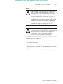
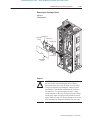
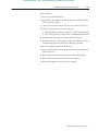
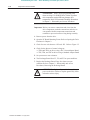
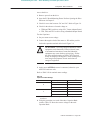
3. Remove the Capacitor Laminated Bus Bar and attached
components.
4. Remove the plastic caps at the four corners of each capacitor
insulator.
5. Remove the capacitors from the drive.
Installation
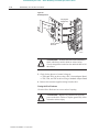
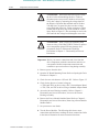
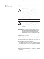
1. Install the capacitor assembly in reverse order of removal. Refer
to Chapter 2 – Disassembly and Access Procedures, Fastener
Torque Specifications.
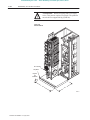
Important: Position the notch and vent hole on the Bus Capacitors
to the top of the drive.
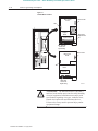
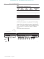
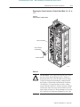
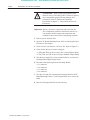
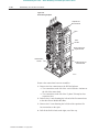
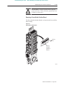
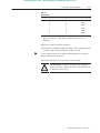
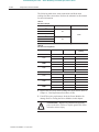
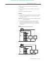
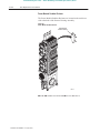
2. Connect the Load-Sharing Resistors to the Bus Capacitors
according to the following diagram. Refer to the schematic
diagrams in this manual for more information on component
configurations.
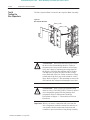
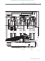
Figure 4.3
Load-Sharing Resistor Connections to Bus Capacitors
D1
+
D2
D3
F1
F2
F3
X
C1 C2 C3 C4
C40
R1
C5 C6 C7 C8
C41
C13 – C24
C25 – C36
R4 – R6
R7 – R9
R2
C9 C10 C11 C12
R3
–
CAP DETAIL
575V
D1
D2
+
D3
F1
F2
F3
X
C40
C1 C2 C3 C4
R1
C41
C5 C6 C7 C8
C9 – C16
C17 – C24
R3 – R4
R5 – R6
R2
–
CAP DETAIL
460V
Publication 1336 FORCE-6.15 – August, 1999