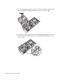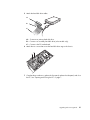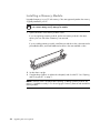
1
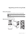
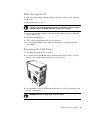
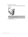
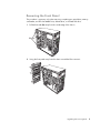
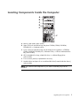
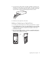
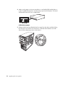
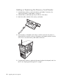
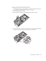
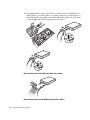
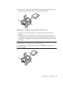
Upgrading and Servicing Guide
The only warranties for Hewlett-Packard products and services are set forth in the express
statements accompanying such products and services. Nothing herein should be construed as
constituting an additional warranty. HP shall not be liable for technical or editorial errors or
omissions contained herein.
HP assumes no responsibility for the use or reliability of its software on equipment that is not
furnished by HP.
This document contains proprietary information that is protected by copyright. No part of this
document may be photocopied, reproduced, or translated to another language without the prior
written consent of HP.
Hewlett-Packard Company
P.O. Box 4010
Cupertino, CA 95015-4010
USA
Copyright © 2000–2006 Hewlett-Packard Development Company, L.P.
May be licensed in the United States by one or both of U.S. Patents Nos. 4,930,158 and
4,930,160 until August 28, 2008.
Microsoft and Windows are U.S. registered trademarks of Microsoft Corporation. The Windows
logo and Windows Vista are trademarks or registered trademark of Microsoft Corporation in the
United States and/or other countries/regions.
HP supports lawful use of technology and does not endorse or encourage the use of our products
for purposes other than those permitted by copyright law.
The information in this document is subject to change without notice.
Table of Contents
Safety Information...................................................................................1
Opening and Closing the PC ...................................................................................1
Preparing the PC ...............................................................................................2
Before Opening the PC ......................................................................................2
After Closing the PC...........................................................................................3
Removing the Side Panel ....................................................................................3
Replacing the Side Panel ....................................................................................4
Removing the Front Panel....................................................................................5
Replacing the Front Panel ...................................................................................6
Locating Components Inside the Computer ...............................................7
Removing and Replacing Drives ...............................................................8
Removing an Optical Drive .................................................................................8
Adding or Replacing an Optical Drive .................................................................9
Removing the HP Pocket Media or Diskette or Hard Disk Drive ..............................11
Adding or Replacing the HP Pocket Media or Diskette or Hard Disk Drive ..............13
Removing the Memory Card Reader ..................................................................15
Adding or Replacing the Memory Card Reader...................................................16
Removing the Hard Disk Drive...........................................................................17
Adding or Replacing a Hard Disk Drive .............................................................19
Adding Memory ....................................................................................22
Removing a Memory Module ............................................................................22
Installing a Memory Module .............................................................................24
Removing or Installing an Add-in Card...................................................25
Removing an Add-in Card ................................................................................25
Installing an Add-in Card..................................................................................26
Replacing the Battery.............................................................................28
Table of Contents
iii
iv
Table of Contents
Upgrading and Servicing Guide
Safety Information
This product has not been evaluated for connection to an “IT” power system (an AC
distribution system with no direct connection to the earth, according to IEC 60950).
WARNING: Please read “Safety Information” in the Warranty and Support
Guide before installing and connecting your system to the electrical power
system.
The Upgrading and Servicing Guide provides instructions on how to remove and replace
hardware components of your PC.
Opening and Closing the PC
Upgrading and Servicing Guide
1
Preparing the PC
Before you upgrade any component in your PC, you need to prepare the PC so that you
can safely handle it and the components.
Read the following items before attempting to upgrade or service the PC:
1 These procedures assume familiarity with the general terminology associated with
personal computers and with the safety practices and regulatory compliance required
for using and modifying electronic equipment.
2 Write down and save the system model and serial numbers, all installed options, and
other information about the system. It’s easier to consult this information than to open
and examine the PC.
3 It is recommended that you use an antistatic wrist strap and a conductive foam pad
when working on the system.
WARNING: Always disconnect the modem cord from the telephone system,
and then disconnect the PC from the power source before removing the front
and side panels of the PC. Failure to do so before you open the PC or do any
procedures can result in personal injury or equipment damage.
Before Opening the PC
To avoid injury and equipment damage, always follow this procedure in this order before
opening the PC:
1 Remove any diskette or optical disc (CD or DVD) from the PC.
2 Click the Windows Start Button®, and then click Shut Down.
3 Disconnect the modem/telephone cable, if present.
CAUTION: To reduce the risk of personal injury from electrical shock or hot
surfaces, disconnect the power cord from the wall outlet, and allow the
internal system components to cool before touching.
4 Disconnect the power cord from the electrical outlet and then from the PC.
5 Disconnect all other attached cables (such as the keyboard, mouse, and monitor).
6 Disconnect all external devices.
CAUTION: Static electricity can damage the electronic components of the PC or
optional equipment. Ensure that you are discharged of static electricity by
briefly touching a grounded metal object.
2
Upgrading and Servicing Guide
After Closing the PC
To avoid injury and equipment damage, always follow this procedure in this order after
closing the PC:
1 Reconnect the power cord.
WARNING: To reduce the risk of electrical shock, fire, or damage to the
equipment, do not plug telecommunications or telephone connectors into the
network interface card (NIC) (labeled as an Ethernet connector).
2 Reconnect the modem/telephone cable and all other cables (such as the keyboard,
mouse, and monitor).
3 Reconnect external devices.
4 Turn on the PC and all peripherals such as the monitor.
5 If you installed an add-in card, install any software drivers supplied by the card
manufacturer.
Removing the Side Panel
1 See “Before Opening the PC” on page 2.
2 Loosen the thumbscrew (A) that secures the side panel to the PC chassis. You may
need to use a screwdriver the first time you loosen the screw.
A
3 Use the handle to pull and slide the panel back about 1 inch (2.5 centimeters), and
then lift it off the chassis.
WARNING: Beware of sharp edges inside the chassis.
Upgrading and Servicing Guide
3
Replacing the Side Panel
1 Align the tabs at the bottom of the side panel to the ridge on the bottom of the chassis.
Place the side panel in the proper position on the chassis and slide it toward the front
of the chassis.
A
NOTE: There is a 3mm gap between the top of the side panel and the top of the
chassis when the side panel is attached properly.
2 Ensure that the hole for the thumbscrew aligns with the hole in the chassis, and then
replace the thumbscrew (A).
3 See “After Closing the PC” on page 3.
4
Upgrading and Servicing Guide
Removing the Front Panel
This procedure is necessary only when removing or replacing an optical drive, memory
card reader, an HP Pocket Media Drive, diskette drive, or the hard disk drive.
1 Pull the three tabs (B) away from the outside edge of the chassis.
B
2 Swing the front panel away from the chassis toward the left to remove it.
Upgrading and Servicing Guide
5
Replacing the Front Panel
1 Align and insert the three hooks on the left side of the front panel with the holes on the
left side of the chassis.
2 Swing the front panel around and press the three hooks on the right side of the front
panel into the three holes on the right side of the chassis until the panel snaps into
place.
6
Upgrading and Servicing Guide
Locating Components Inside the Computer
A
B
C
D
E
F
A Memory card reader (select models)
B Upper 5.25-inch optical drive bay, may be a CD-ROM, CD-RW, DVD-ROM,
DVD+RW/+R, or combination drive
C Lower 5.25-inch optical drive bay, may be empty (knockout plate) or a CD-ROM,
CD-RW, DVD-ROM, DVD+RW/+R, combination drive, or HP Personal Media Drive
bay (select models)
D HP Pocket Media Drive bay, a hard disk drive, or a diskette (floppy) drive
(select models)
E
Front connector panel (no replacement instructions)
F
Hard disk drive and space for a second hard disk drive (located inside the chassis)
(select models)
NOTE: The connectors and components of your chassis model may vary from the
illustration.
Upgrading and Servicing Guide
7
Removing and Replacing Drives
Your PC has several drives that you can replace or upgrade. See the preceding topic,
“Locating Components Inside the Computer” on page 7 for drive type and location.
The hard disk drive is either a Serial ATA (advanced technology attachment) drive, which
uses a narrow data cable, or a Parallel ATA drive, which uses a wide data cable.
Select models have a second hard disk drive.
CAUTION: Back up your personal files on the hard disk drive to an external
storage device, such as a CD, before removing the hard disk drive. Failure to
do so will result in data loss. After replacing the hard disk drive, you need to
run System Recovery using the recovery discs to load the factory-installed files.
See the user documentation that came with your PC for details about the
recovery procedure.
You can add an optical drive into an empty lower optical drive bay.
IMPORTANT: Before adding a new optical drive, make sure that it is compatible with the
Microsoft Windows Vista™ operating system. Also, make sure you have the correct
software and drivers for the optical drive to work with the operating system.
Removing an Optical Drive
1 Complete the procedures to prepare the PC to remove the side panel and to remove
the front panel. See “Opening and Closing the PC” on page 1.
2 Release the drive by pulling the latch out away from the chassis and then pulling the
drive part way out of the front of the chassis. (The latch drive brackets secure the
drives in their respective positions in the chassis.)
8
Upgrading and Servicing Guide
3 Disconnect the power, data, and the sound cable, if available, from the back of the
optical drive you want to remove. For most drive cables, use a gentle rocking motion
to free the plug. For Serial ATA hard disk drive cables, press the latch (select models
only) in the center of each plug, and pull the plug from the drive connector.
4 Pull the drive out through the front of the chassis.
Adding or Replacing an Optical Drive
1 If necessary, remove the existing drive. See “Removing an Optical Drive” on page 8.
2 If you are adding a drive to an empty lower optical drive bay, you must remove the
knockout plate from the bay. To do so, insert a flat screwdriver into the knockout plate
slot (A) and rotate the screwdriver to break the knockout plate out of the chassis.
Discard the knockout plate.
3 Remove the knockout plate on the front cover. To do so, insert a flat screwdriver into
the knockout plate slot (B) and rotate the screwdriver to break the knockout plate out
of the front cover. Discard the knockout plate.
A
B
Upgrading and Servicing Guide
9
4 Make sure the jumper on the new optical drive or new Parallel ATA hard disk drive is
in the CS (Cable Select) position. Your drive may vary from the illustration. The Serial
ATA hard disk drive does not use Cable Select.
CS SL MA
Cable Select jumper
5 Release the drive bay by pulling the latch out away from the chassis and then sliding
the drive part way into the front of the chassis. (The latch drive brackets secure the
drives in their respective positions in the chassis.)
10
Upgrading and Servicing Guide
6 Connect the power and data cables from the back of the optical drive you want to
add. Reconnect the sound cable, if present.
WARNING: For a second Parallel ATA drive, make sure to connect the data
cable labeled Master to the primary hard disk drive, and the data cable
labeled Slave to the secondary hard disk drive. If the data cable is not
connected correctly, the PC is unable to locate the hard disk drive and data
may be lost.
7 Make sure the drive is pushed all the way in through the front of the chassis until it
locks into place.
8 Make sure the drive latch pin is fully inserted into the hole labeled (2).
9 Complete the procedures to replace the front panel, replace the side panel, and close
the PC. See “Opening and Closing the PC” on page 1.
Removing the HP Pocket Media or Diskette or
Hard Disk Drive
1 Complete the procedures to prepare the PC to remove the side panel and to remove
the front panel. See “Opening and Closing the PC” on page 1.
2 Release the HP Pocket Media or diskette (floppy), or hard disk drive, by removing the
two screws on the side of the drive, and then slide the drive part way out of the front
of the chassis.
Upgrading and Servicing Guide
11
3 Disconnect the power and data cables from the back of the drive by squeezing the
two latches and pulling the cable.
MA
ST
ER
SLA
VE
To
C
PU
4 Pull the drive out through the front of the chassis.
12
Upgrading and Servicing Guide
Adding or Replacing the HP Pocket Media or
Diskette or Hard Disk Drive
1 Complete the procedures to remove the HP Pocket Media, diskette (floppy), or hard
disk drive, if necessary. See “Removing the HP Pocket Media or Diskette or Hard Disk
Drive” on page 11.
2 Slide the HP Pocket Media, diskette (floppy), or hard disk drive into the front of the
chassis until it locks into place.
3 Align the two screw holes on the chassis with the two screw holes on the side of the
drive, and then attach the two screws. For the HP Pocket Media and diskette (floppy)
drive, make sure to insert the screw into the holes labeled (2). For a hard disk drive,
make sure to insert the screw into the holes labeled HDD.
Upgrading and Servicing Guide
13
4 Connect the power and data cables to the back of the HP Pocket Media, diskette
(floppy), or hard disk drive.
A
B
MA
ST
ER
SLA
VE
C
To
C
PU
A — Connect to a primary hard disk drive.
B — Connect to a secondary hard disk drive (select models only).
C — Connect to the PC motherboard.
5 Complete the procedures to replace the front panel, replace the side panel, and close
the PC. See “Opening and Closing the PC” on page 1.
14
Upgrading and Servicing Guide
Removing the Memory Card Reader
1 Complete the procedures to prepare the PC to remove the side panel and to remove
the front panel. See “Opening and Closing the PC” on page 1.
2 Release the drive by removing the screw on the top of the memory card reader, sliding
the reader to the left to loosen it, and then pulling the memory card reader part way
out of the front of the chassis.
3 Disconnect the cable from the back of the memory card reader.
4 Pull the memory card reader out of the front of the chassis.
Upgrading and Servicing Guide
15
Adding or Replacing the Memory Card Reader
1 Complete the procedures to remove the memory card reader, if necessary. See
“Removing the Memory Card Reader” on page 15.
2 Slide the memory card reader part way into the front of the chassis.
3 Attach the cable to the back of the memory card reader.
4 Push the memory card reader into the chassis until the screw hole on the chassis is
aligned with the screw hole on the top of the memory card reader, and then insert the
short screw to secure the memory card reader to the chassis.
5 Complete the procedures to replace the front panel, replace the side panel, and close
the PC. See “Opening and Closing the PC” on page 1.
16
Upgrading and Servicing Guide
Removing the Hard Disk Drive
1 Complete the procedures to prepare the PC to remove the side panel and to remove
the front panel. See “Opening and Closing the PC” on page 1.
2 Lay the computer gently on its side.
3 Remove the two screws that secure the hard disk drive cage to the chassis.
4 Push down the latch on the side of the hard disk drive cage, and then slide the hard
disk drive cage away from the bottom of the chassis as shown below.
Upgrading and Servicing Guide
17
5 Lift the hard disk drive cage out of the chassis, and then remove the hard disk drive
cables (1, 2). For most drive cables, use a gentle rocking motion to free the plug. For
Serial ATA hard disk drive cables, press the latch (5) (select models only) in the center
of each plug (6), and pull the plug from the drive connector.
6
5
2
1
Disconnecting the Serial ATA hard disk drive cables
MA
ST
ER
SLA
VE
To
C
PU
Disconnecting the Parallel ATA hard disk drive cables
18
Upgrading and Servicing Guide
6 Remove the four screws that secure the hard disk drive to the hard disk drive cage,
and then slide the hard disk drive out of the hard disk drive cage.
Adding or Replacing a Hard Disk Drive
1 If necessary, remove the existing drive. See “Removing the Hard Disk Drive” on
page 17.
2 Slide the new drive into the hard disk drive cage, aligning the drive with the four
screw holes on the cage. Install the four screws that secure the hard disk drive to the
hard disk drive cage. Make sure the hard disk drive cables are facing the top of the
drive cage.
NOTE: If you are replacing an old drive with a new drive, remove the four guide screws
from the old drive, and use the screws to install the new drive.
If you are installing a second hard disk drive, use four standard 6-32 screws that you
purchase separately.
Upgrading and Servicing Guide
19
3 Place the hard disk drive cage into the chassis. The two screw holes on the hard disk
drive cage (A) should be aligned with the screw holes on the chassis (B).
A
B
4 Align the four guides on the bottom of the hard disk drive cage with the holes on the
back of the chassis, and then slide it down toward the bottom of the chassis until it
locks into place.
20
Upgrading and Servicing Guide
5 Attach the hard disk drive cables.
A
B
MA
ST
ER
SLA
VE
C
To
C
PU
A — Connect to a primary hard disk drive.
B — Connect to a secondary hard disk drive (select models only).
C — Connect to the PC motherboard.
6 Attach the two screws that secure the hard disk drive cage to the chassis.
7 Complete the procedures to replace the front panel, replace the side panel, and close
the PC. See “Opening and Closing the PC” on page 1.
Upgrading and Servicing Guide
21
Adding Memory
Your PC comes with random access memory (RAM), which temporarily stores data and
instructions on your PC. The PC ships with one or more memory modules, but you can
replace the existing memory module(s) with higher-capacity ones.
The motherboard contains sockets for DDR DIMMs (double data rate dual in-line memory
modules). The exact number of sockets and type of DDR memory module depends on
which model PC you have.
DDR DIM
To determine which type and speed of memory module your PC uses, and for specific
memory module information and specifications, go to the Web site listed in your Warranty
and Support Guide, and click the Support link.
WARNING: Using the wrong type of memory module could damage the
system.
22
Upgrading and Servicing Guide
Removing a Memory Module
1 Complete the procedures to prepare the PC and to remove the side panel. See
“Opening and Closing the PC” on page 1.
2 Gently lay the PC on its side.
3 Locate the memory sockets on the motherboard.
CAUTION: When handling a memory module, be careful not to touch any of
the contacts. Doing so may damage the module.
4 Move any cabling out of the way, if necessary.
5 Push down the two retaining clips on the ends of the memory socket until the memory
module pops out of the socket.
WARNING: Do not pull the memory module out of the socket. Use the retaining
clips to remove the module.
6 Lift the memory module from the memory socket.
Upgrading and Servicing Guide
23
Installing a Memory Module
Upgrade the memory in your PC with memory of the same type and speed as the memory
originally installed in your PC.
CAUTION: When handling a memory module, be careful not to touch any of
the contacts. Doing so may damage the module.
1 Open both latches of the memory module socket:
If you are replacing a memory module, put the new memory module in the same
memory slot from which the old memory was removed.
Or
If you are adding a memory module, install the new module into the socket nearest the
preinstalled module, and install additional modules in the next available sockets.
2 Set the chassis upright.
3 Complete the procedures to replace the side panel, and close the PC. See “Opening
and Closing the PC” on page 1.
NOTE: If a blank screen is displayed after replacing or adding a memory module, the
memory is installed incorrectly or it is the wrong type of memory. Remove and reinstall the
memory module.
24
Upgrading and Servicing Guide
Removing or Installing an Add-in Card
An add-in card is a circuit board, such as a PCI or an AGP card, that fits into a PC add-in
card slot. Your PC contains several add-in card slots that can be used to add components
to your PC. The PC component configurations vary by model.
WARNING: Do not overload the system by installing add-in cards that draw
excessive current. The system is designed to provide two amps (average) of
+5 Vv power for each board/card in the computer. The total +5 Vv current
draw in a fully loaded system (one with all add-in card slots filled) must not
exceed the total number of slots multiplied by two amps.
A flat-head and a Phillips screwdriver are needed to remove, replace, or add an
add-in card.
NOTE: A power supply upgrade may be required for certain graphics card upgrades.
Check with the graphics card supplier for more information about power supply
requirements.
Upgrading and Servicing Guide
25
Removing an Add-in Card
1 Complete the procedures to prepare the PC and to remove the side panel. See
“Opening and Closing the PC” on page 1.
2 Gently lay the PC on its side.
3 On the back of the PC, remove the screw from the bracket cover for the add-in card
slots, and then remove the bracket cover.
4 Inside the PC, locate the add-in card slots on the motherboard.
WARNING: Be careful of the sharp edges on the add-in card slot cover.
5 Remove the slot cover. Hold the card at each end, carefully rock it back and forth until
the connectors pull free from the socket, and then remove the card. Or you can insert
a flat screwdriver into the knockout plate slot (A) and rotate the screwdriver to break
the knockout plate. Be sure not to scrape the card against the other components. Store
the old card in the anti-static packaging that contained your new card.
A
6 If you are not replacing the old add-in card with a new add-in card, close the open
slot by inserting the metal slot cover into the opened slot.
26
Upgrading and Servicing Guide
Installing an Add-in Card
1 Align the edge of the add-in card with the slot on the chassis and gently but firmly
press the card straight down into the add-in card slot. The whole connector should be
seated properly in the card slot.
2 On the back of the PC, replace the bracket cover for the add-in card slots, and then
install the screw.
3 Set the chassis upright.
4 Complete the procedures to replace the side panel, and close the PC. See “Opening
and Closing the PC” on page 1.
NOTE: If the new card or device isn’t working, read through the card manufacturer’s
installation instructions and recheck all connections, including those to the card, power
supply, keyboard, and monitor.
Upgrading and Servicing Guide
27
Replacing the Battery
A lithium battery on the motherboard provides backup power for the PC’s timekeeping
ability. The battery has an estimated life expectancy of seven years.
When the battery starts to weaken, the date and time may be incorrect. If the battery fails,
replace it with a CR2032 lithium battery (3 volt, 220mAH rating) or an equivalent battery.
WARNING: There is danger of explosion if the battery is incorrectly replaced.
Replace only with the same, or equivalent, type of battery. Discard used
batteries according to the manufacturer’s instructions.
1 Complete the procedures to prepare the PC and to remove the side panel. See
“Opening and Closing the PC” on page 1.
2 Gently lay the PC on its side.
3 Remove any cabling, if necessary, to reach the battery.
4 Remove any memory modules, if necessary, to reach the battery. See “Adding
Memory” on page 22.
5 To remove the battery, push the latch away from the battery and lift the battery from
the socket.
6 Install the new CR2032 battery in the socket, with the positive (+) side facing the
latch.
7 Replace the memory modules or cables you removed.
8 Set the chassis upright.
9 Complete the procedure to replace the side panel, and to close the PC. See “Opening
and Closing the PC” on page 1.
Part number: 5991-6989
28
Upgrading and Servicing Guide