1
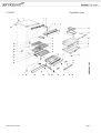
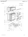
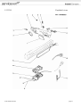
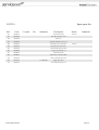
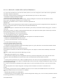
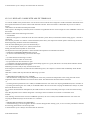
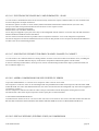
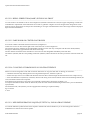
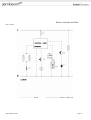
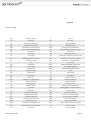
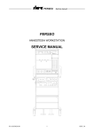
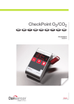
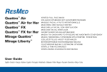
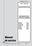
Model type:
TNFP3303TEL
Commercial code:
General notes
Technical Documentation guidelines
---------------------------------------------------------------------------------------------------------------------------------------------------------------------------------------------You can find herewith some generic information to simplify cunsulting of technical documentation:
1. Models of same range share the same exploded views, which report the richest set of spare parts:generally, a model does not
necessarly have a related spare part for each particular shown on exploded views.
2. Some spare parts can not be represented directly on the exploded views (instruction booklets, specific kit, etc...). You can find
those codes in the spare parts list with the same reference of particular where spares are installed or with references 099, 999.
Instruction booklets, once managed, appear with 000 reference.
3. On the higher right site of each exploded view there is a serial number which indicates the beginning of the production of
certain range:some models might have more than an exploded view for a given category, each distinguished by a different serial
no.and linked to another spare parts list, In this case, serial no. is required to supply the right spare part code. Exploded view to be
considered is the one with a more recent serial no. but previous than the one of the model that needs assistance.
4.Exploded views might require further updates even after publishing. Addition of new spares will go on following the already
existing numeration references. Revision number of an exploded view is shown into last four digits of serial number into upper
right hand corner.
5.The spare parts list associated to an exploded view shows related codes of spares managed for a certain model; for each spare
part other informations are available:
REF: reference no of spare into a table; SUBSTITUTE: list of spare(s) which can replace a code but that keeps same functional
characteristics
INDUSTRIAL CODE: list of variables of a model (shown into model label) where such spare is used; NOTICE: code of
information(s) to refer to complete technical intervention, track for changes or to find correct spare part code.
6. Some notices, into a same section are generic therefore cannot be directly linked to a spare part. In order to assist a model in
the best way as possible, it is helpful to pay attention to all notices and constantly verify documentation updates
7.Technical documentation cover shows model name and its commercial codes
mod.TNFP3303TEL
page 2
5133030
mod.TNFP3303TEL
Exploded views
page 3
5133030
Spare parts list
Ref.
Code
001
С сер.№
По
Substitute
Description
C00016413
1 x C00028137
cord lead'rf340-rf340el'
002
C00026582
1 x C00040183
white26 cover 600x492x32 (hole-
002
C00040183
white26 cover 600x492x32 (hole-
003
C00026590
white26 dashboard base no-frost
003
C00040189
white26 dashboard base no-frost
004
C00021990
hinge upper lh
004
C00021991
hinge upper rh
005
C00015745
hinge pin - m6x(5+14)
007
C00028437
grey11 set dashbpard m.60
007
C00030660
grey11 set dashboard m.60(20
009
C00025232
white upper meat-holder tray
010
C00025231
neutral col.44 flap tray meat-
011
C00025229
white lower meat-holder tray
012
C00025230
013
C00025891
2 x C00032223
no-slip gasket central hinge
014
C00025907
1 x C00042672
zncr central hinge (non-slip
Notice
Industrial
0513189
slide foot (lower meat tray) - white
1 x C00042673
015
C00023305
white grid inclinable wxhxd
016
C00023304
white retracting grid
017
C00023303
white overturnable grate
018
C00023316
trim - wire shelf white
019
C00024308
white lateral pipe separator
020
C00024273
white separator
021
C00024301
front plate (fridge floor) - white
022
C00022011
lower hinge chromium
023
C00017812
024
C00022013
separator fixing plate chromium
0513254
024
C00047949
separator fixing plate cromium
0513254
025
C00024340
runner spacer rh - white
025
C00024341
runner spacer lh - white
026
C00024290
separator refrigerator runner dx
026
C00024292
separator refrigerator runner sx
026
C00029242
runner support rh
026
C00029243
runner support lh
027
C00024305
support (fridge floor) - white
mod.TNFP3303TEL
1 x C00032099
0513254
0513253
hinge pin (m8x5-20)
page 4
5133030
Spare parts list
Ref.
Code
028
C00022017
029
C00023283
030
C00023297
031
C00017771
foot 10x36- adjustable
031
C00032232
foot support m10 (37x55 mm)
032
C00023300
support rh (wire shelf) - white
032
C00023301
support lh (wire shelf) - white
033
C00021591
034
C00026592
035
C00021989
036
C00023299
038
C00011286
039
C00017792
mod.TNFP3303TEL
С сер.№
По
Substitute
Description
Notice
Industrial
винт m5x15 ts
base dx-sx aluminium
1 x C00043862
1 x C00041042
lower hinge dx-sx zncr
"o" washer 8x4x2 - thermostat
disc (temperator sensor probe) -
1 x C00022198
blue swab refrigerator 20x30
bush 6,8mm (wire shelf) - white
1 x C00114785
заглушка белая d.4,5x8 mm
spacer - condenser
page 5
5133130
mod.TNFP3303TEL
Exploded views
page 6
5133130
Spare parts list
Ref.
Code
С сер.№
По
Substitute
Description
001
C00026570
002
C00024267
втулка белая 7x21,5 mm
003
C00025238
white inner door freezer'impronta
004
C00025241
005
C00023280
aluminium recessed knob door
006
C00022166
white bush for door stop (h=6mm)
007
C00026519
blanking plug white 26 (bush)
008
C00023343
втулка белая с отверстием
009
C00025236
cover - small box white
010
C00025237
1 x C00032298
small garlic box - white
010
C00026609
1 x C00030609
white smal box for onion
010
C00026610
small lemon box - white
011
C00023312
лоток для яиц (9) белый
012
C00023272
012
C00026551
1 x C00023341
white boxes shelf serig.(no-frost)
012
C00026722
1 x C00023270
white shelf bottle mod.600 (no-
013
C00023342
015
C00025235
016
C00025233
017
C00025234
white smal sink for marsupial
018
C00022165
white bush for door stop
019
C00022029
screw m5x14 tc
020
C00022030
shoulder screw m5x10 - door
021
C00022017
винт m5x15 ts
022
C00022031
Notice
Industrial
push-button (fan no-frost) - white
1 x C00028106
white freezer shelf mod.600 (no-
sliding separator (bottle shelf) -
hinged shelf (218mm) - white
white separator for marsupial shelf
1 x C00028112
1 x C00029240
white shelf with marsupial
white runner drawer dx blum
1 x C00029241
1 x C00029242
1 x C00029243
1 x C00029965
1 x C00029966
022
C00022032
1 x C00029240
white runner drawer sx blum
1 x C00029241
1 x C00029242
1 x C00029243
1 x C00029965
mod.TNFP3303TEL
page 7
5133130
Spare parts list
Ref.
Code
022
C00029240
022
C00029241
023
C00022033
023
C00022154
plastic washer (12x6,1x3mm) -
024
C00024276
adjustable drawer rack -
025
C00022034
plate m5 (20x20x4)
026
C00022076
drawer partition - white
027
C00024288
cellar drawer (w= 491 mm) -
028
C00024278
прокл. серая y58 дверцы отд.
029
C00024350
030
C00024337
aluminium third door frame (wxh
031
C00024349
aluminium recessed knob85 third
032
C00024347
white door liner refrigerator(bxh
033
C00024279
прокладка дверцы
034
C00024348
white26 refrig.door recessed
035
C00024339
aluminium refrige.door
036
C00023808
alum.recessed knob refrigerator
037
C00023367
aluminium label holder tropical
038
C00025240
прокладка дверцы морози-ка
039
C00025239
freezer inner door insulation
040
C00023511
white26 frezer door recessed
041
C00023500
freezer door frame
042
C00021255
blanking plug (8,5mm) - white
mod.TNFP3303TEL
С сер.№
По
Substitute
Description
Notice
Industrial
drawer runner lh - white
drawer runner rh - white
1 x C00065734
1 x C00024285
drawer angle bracket - white
0513185
white26 third door recessed
page 8
5133220
mod.TNFP3303TEL
Exploded views
page 9
5133220
Spare parts list
Ref.
Code
С сер.№
По
Substitute
001
C00026608
ванночка для льда 246x110
002
C00007225
пластиковый упругий стопор
003
C00026607
cover - ice tray (plastic)
004
C00025221
005
C00026597
ice tray support- white
006
C00025227
freezer flap door (l=342)- colour
007
C00026593
панель акк. холода белая с
008
C00026598
white separator freezer(493x276)
010
C00014612
расширитель
011
C00025228
freezer base tray (494x351) -
012
C00025223
днище морозильной камеры
015
C00026681
pipes grommet (de.24 x 21 mm)
016
C00026682
fuse-thermic fixing plate (no-frost)
017
C00025211
freezer evaporator (b=350x153)
018
C00026614
drip w.outlet pipe-rubber
018
C00028100
non return valve - defrost water
018
C00028101
connector - defrost pipe/non
019
C00026947
020
C00028114
021
C00010517
screw m6
023
C00008591
earth plate compressor aspera-
025
C00013997
028
C00006495
029
C00008471
030
C00017856
1 x C00104762
compressor b1116a-b1116b 220-
030
C00025755
1 x C00104762
comp.embraco ff8,5bk 220-240v
031
C00009319
1 x C00042354
charging pipe 6x70
031
C00031162
032
C00006418
filter
033
C00023282
конденсатор h=1000+200x591
1 x C00117027
Description
Notice
Industrial
ванночка для льда белая
0513231
0513181
drip water outlet pipe sping (no1 x C00009337
defrost water tray - metal
держатель компрессора 586 x
1 x C00032453
rubber shock absorber пластина крепления
0513203
0513218
mod.TNFP3303TEL
suction connection -
0513205
page 10
5133330
mod.TNFP3303TEL
Exploded views
page 11
5133330
Spare parts list
Ref.
Code
001
Description
Notice
C00026612
white false knob box
0513223
001
C00038969
white false knob box center-
002
C00023288
lamp cover
003
C00006522
лампочка 220-240 в/15 вт (e14)
004
C00023295
thermostat box(no switch hole)-
004
C00038970
thermostat box white center-
005
C00007225
пластиковый упругий стопор
006
C00009882
патрон для лампочки e14
007
C00009888
кабельный зажим
008
C00008867
выключатель освещения libero
009
C00023294
white push-button light switch
010
C00010097
015
C00026725
mod.TNFP3303TEL
С сер.№
По
Substitute
1 x C00029307
Industrial
0513223
supply cable 3x0,75
anti condensation heater 5w
page 12
5133420
mod.TNFP3303TEL
Exploded views
page 13
5133420
Spare parts list
Ref.
Code
С сер.№
По
Substitute
Description
Notice
001
C00028437
grey11 set dashbpard m.60
0513189
001
C00030660
grey11 set dashboard m.60(20
002
C00025243
fan push-button n.a. 1051 (no-
003
C00025215
прокладка резиновая двигателя
004
C00025218
fan blade (mes)
005
C00026604
1 x C00026601
probe eutectic l.850 mm faston
0513189
005
C00027214
1 x C00027220
probe refrigerator l.1200 mm
0513189
005
C00027220
probe refrigerator l.1450 mm
0513189
005
C00028105
датчик аккум. холода l.850mm
005
C00030655
1 x C00032408
probe refrigerator l.1450 mm
005
C00030656
1 x C00028104
probe refrigerator l.1200 mm
006
C00026591
cover (temperature sensor) - white
008
C00026606
card mask microprocessor
008
C00027258
Industrial
0513189
0513191
1 x C00026606
card masck microprocessor faston
0513191
0513193
008
C00030657
008
C00030658
009
C00025244
insulation lower box (no-
010
C00026652
adhesive sponge seal (7x610x4)
011
C00026654
adhesive sponge seal (30x150x4)
012
C00025245
lower cover - grey
013
C00026960
wiring bush (no-frost)
014
C00026687
wiring protection 194 mm (no-
014
C00028116
wiring protection 194mm (no-
015
C00026633
upper cover - grey
016
C00025210
defros.res.20w 220v(faston)
1 x C00030657
плата микропроцессора .masк
0513192
card masck microprocessor molex
0513193
0513189
0513212
016
C00028085
нагреватель для оттаивания 20
0513212
017
017
C00027622
тэн 72 вт 220 в (faston)
0513189
C00028084
элемент нагрев. 72 вт 220 в
018
C00025216
018
C00028078
019
C00025217
021
C00027222
mod.TNFP3303TEL
1 x C00028078
fan-motor (mes-plaset) connector
0513189
двигатель вентилятора
cover - fan-motor
1 x C00028083
therm.elth261177 + fuse
0513189
page 14
5133420
Spare parts list
Ref.
Code
021
C00028083
021
C00030291
adhesive small spogne
022
C00026790
10 wire flat cable display
022
C00028069
20 wire flat cable display board
mod.TNFP3303TEL
С сер.№
По
Substitute
Description
Notice
Industrial
тепл. защ. реле elth 261n356 +
0513189
page 15
Notices
0513178: 3W HEATING ELEMENT FOR SEPARATOR IN "CELLAR" COMPARTMENT
-----------------------------------------------------------------------------------------------------------------------------------------------------------------------------------------------
The current anticondensation resistance mounted in the separator of the refrigerator compartment of the 3 door models has been
modified as follows: the length according to the 600 or 550
refrigerator module; the type of cap or faston terminal for connection to the terminal board.
The following prospectus illustrates the resistances which are currently used:
.BF bold
Models DF2853T and DF330S3T module 600 in class N and T
.pf
026585 - 3W 220V, 325 mm long resistance with cap terminals.
This resistance will also be used on the new no-frost mechanical models.
026725 - 3W 220V, 325 mm long resistance with 4,8x0,8
female faston terminals.
This resistance is used specifically for all the electronic versions of the no-frost models. An Aspera B1116A compressor will in
fact be mounted on these models with a Blu-Box type terminal board with faston connections.
.bf bold
Models DF2603T and KDF2603T module 550
.pf
024274 - 3W 220V, 285 mm long resistance with cap terminals.
This resistance is used specifically for models DF2603T with exception of the French version produced under the (NF) trademark.
022050 - 3W 220V, 285 mm long resistance with 4,8x0,8
female faston terminals.
This resistance is used specifically for model DF2603TF, produced for France under the (NF) trademark.
0513181: NO-FROST FREEZER EVAPORATOR MADE TO RUN QUIETER
-----------------------------------------------------------------------------------------------------------------------------------------------------------------------------------------------
The modification for the noiseless freezer evaporator has been introduced as from serial no. 802010001 on the no-frost
mechanical and electronic versions.
The following parts have been modified:
025211 - ventilated evaporator (h=1590 mm) (The position of the input and output pipes is 30 mm lower and the diameter of the
delivery pipe has been reduced from 6 to 4 mm)
025222 - freezer bottom insulation (the bottom corners project by 30 mm)
The new freezer evaporator may be used to replace the old type. In this case however the fixing holes on the freezer cell should
be re-made with a 3 mm diameter bit (depth 10 mm).
-VT cell and NT evaporator take the holes 32 mm higher
The old fixing holes of the evaporator should be closed with silicone.
mod.TNFP3303TEL
page 16
The modified insulation bottom should also be installed.
If the old evaporator is to be used instead of the new type, the following problems will be encountered:
-when the new holes are made on the freezer cell (NT cell and VT evaporator take the holes 32 mm lower), the holes coincide
outside the sheet plate reinformcement behind the refrigerator cell side.
-the freon in the old evaporator starts expanding in the rising section of the delivery pipe (immediately after the weld to the
capillary) and therefore the evaporator is noisy.
Noise on the new evaporator has been eliminated by modifying the diameter of the delivery pipe: external diameter reduced from
6 to 4
mm and the internal diameter from 4 to 2 mm in order to have a direct connection to the capillary.
In addition the section of the delivery pipe connection to the freezer evaporator coil terminates as a Venturi pipe.
With these modifications the freon starts to expand inside the freezer, immediately after the weld between the Venturi pipe and
the coil in the horizontal section of the upper part of the evaporator.
In addition using the old evaporator on the new products, the 30 mm which project from the bottom corner of the bottom
insulation must be removed.
The new freezer evaporator and the new freezer bottom insulation will be indicated under the same sat codes as the previous
versions.
0513185: REPLACEMENT OF PLATE (20X20) FOR FASTENING GUIDES ON 3-DOOR UNITS
-----------------------------------------------------------------------------------------------------------------------------------------------------------------------------------------------
On the three-door version refrigerators, the M5x15TS (022017) screw used for fixing the guides to the refrigerator separator or to
the cellar compartment drawer, has been replaced by 8Px19,5xTSP self-threading screws.
The 8Px18x12 plate must be used with the self-threading screw instead of the square M5 (022034) plate.
On the refrigerator separator and on the cellar compartment drawer the plate housings have been modified (the depth has been
decreased from
10,1 to 7,1 m.).
On the new modified parts the previous fixing system may be used by changing the sizes of the square plate from 20x20 to 20x14
mm .
The new fixing system may be used on premodification models.
The modified spare parts are indicated under the previous sat code.
0513189: NOTICE FOR MOLEX CONNECTIONS ON NO-FROST FRIDGE
-----------------------------------------------------------------------------------------------------------------------------------------------------------------------------------------------
As from serial no. 903150001 the new Molex connector system will be introduced in all no-frost refrigerators.
The new spare pars with molex attachments are not interchangeable with premodification parts. The description for the spare
parts has been changed by adding the word Molex or FASTON to indicate the type of attachment.
The ELTH 261356 (028083) thermoprotector has different attachments and new ratings (activates at +8°C/disactivates at
-10°C) with respect to the previous model, the ELTH 261177 (027222).
With the new ratings the plastic plate fitted during assembly on the freezer evaporator has been eliminated (definitely for all
versions); the adhesive sponge (030291) is still fitted around the thermoprotector.
On the electronic version the dashboard unit (030659
030660-030661-030662-030663) are fitted with a flat 20 wire cable connecting these to the electronic board with Molex
attachments. On the previous version the dashboard and the electronic board with Faston attachments are connected with the
round 10 wire cable.
The description of the dashboard unit NT and VT indicates whether this is for the 10 or 20 wire cable.
The flat cable has led to the modification of the cabling sheath
026687 which has been replaced by the 028116. The latter may also be fitted on premodification models.
mod.TNFP3303TEL
page 17
0513191: RELEASE2 CARDS WITH FASTON TERMINALS
-----------------------------------------------------------------------------------------------------------------------------------------------------------------------------------------------
As a result of the introduction of new electronic boards (release-2) on no-frost refrigerators, these boards will be supplied both
with Molex and Faston attachments.
The release-2 boards with Faston attachments will be indicated under the previous sat codes (release-1):
-code 026606 for Italian and European models
-code 027258 for Spanish and Greece models
These new boards are interchangeable with the release-1 board (including the version with radio anti-disturbance filter).
With respect to the diagram (5130412A) shown in the Servicing
Manual the new boards have the AC contacts on the bottom right hand side.
IMPORTANT
Release-1 boards can be transformed into release-2 boards by replacing the microprocessor integrated with other components on
the main board. In this case the AC contacts remain on the bottom left hand side.
---AUTOTEST
---When the refrigerator is switched On the first time and after a power failure, an automatic autotest lasting approx. 1 minute is
carried out.
This autotest procedure is as follows: all the LEDs flash (three times), the compressor and fan operate continuously, the freezer
defrosting heating elements switch ON intermittently.
After the initial flashing the system sets automatically to
+5°C in the refrigerator and at -12°C (alarm) in the freezer.
During the autotest the keyboard can not be used.
The keyboard can be used again after 1 minute and the real temperature is indicated in the freezer.
---FORCING A FREEZER DEFROSTING CYCLE
---To activate a forced defrosting cycle follow these steps:
:sl
---a) Check that the fast freezing is not ON.
If necessary press the button to switch OFF.
---b) Open the freezer door and leave it open.
---c) Hold down the alarm pushbutton (buzzer) until a Beep signal is il is given (after about 5 seconds) which indicates that the
forced defrost command has been accepted.
Defrosting now starts and you may close the freezer door.
If the compressor and fan are ON when the forced defrosting starts, the compressor switches OFF immediately whilte the fan
switches
OFF after 3 minutes and only then does the defrosting cycle start.
:esl
---SWITCHING ON THE LED -24°C (SUPER).
---The thermometer readings have been "manipulated" so that they visualize the temperature in the storing area and not the
temperature where the foodstuff to be frozen has been stored. The thermometer therefore behaves as follows:
:sl
---a) During normal operation the -24°C LED (or SUPER LED in the case of the new restyling-88 dashboard) never switches on.
---b) During fast freezing the -24°C LED (or the SUPER LED in the case of the new restyling-88 dashboard) is always on (other
than when the alarm is ON).
To "conceal" the thermometer manipulation, this LED switches on with a certain delay with respect to the start of the freezing
cycle.
This delay depends on how cold the refrigerator is and ranges from a minimum of 5 minutes to a maximum of 60
minutes.
After freezing, when the freezer returns to NORMAL operation, the -24°C LED (or the SUPER LED in the case of the new
restyling-88 dashboard) stays ON for another 4 or 5 minutes.
:esl
---DEFROSTING DURING FAST FREEZING
---All the defrosting cycles are stopped in the first 11 hours during the fast freezing cycle, so as to avoid any interference with the
first freezing phase which is the most important.
mod.TNFP3303TEL
page 18
A freezer defrost cycle is always carried out after the 11th hour.
0513192: RELEASE2 CARDS WITH MOLEX TERMINALS
-----------------------------------------------------------------------------------------------------------------------------------------------------------------------------------------------
As from the middle of July-89 the release 1/A electronic board on the No-frost refrigerator models with Molex attachments have
been replaced with the new release-2 board with automatic autotest. These new board is coded under the previou sat code as
follow:
code 030657 for the Italian and European models
With respect to the diagram (5130652A) shown in the Servicing Manual the new card no longer have the "JAMPER" contacts for
the autotest.
Release-2 board has the following innovations:
---AUTOTEST
---When the refrigerator is switched On the first time and after a power failure, an automatic autotest lasting approx. 1 minute is
carried out.
This autotest procedure is as follows: all the LEDs flash (three times), the compressor and fan operate continuously, the freezer
defrosting heating elements switch ON intermittently.
After the initial flashing the system sets automatically to
+5°C in the refrigerator and at -12°C (alarm) in the freezer.
During the autotest the keyboard can not be used.
The keyboard can be used again after 1 minute and the real temperature is indicated in the freezer.
---FORCING A FREEZER DEFROSTING CYCLE
---To activate a forced defrosting cycle follow these steps:
:sl
---a) Check that the fast freezing is not ON.
If necessary press the button to switch OFF.
---b) Open the freezer door and leave it open.
---c) Hold down the alarm pushbutton (buzzer) until a Beep signal is il is given (after about 5 seconds) which indicates that the
forced defrost command has been accepted.
Defrosting now starts and you may close the freezer door.
If the compressor and fan are ON when the forced defrosting starts, the compressor switches OFF immediately whilte the fan
switches
OFF after 3 minutes and only then does the defrosting cycle start.
:esl
---SWITCHING ON THE LED -24°C (SUPER).
---The thermometer readings have been "manipulated" so that they visualize the temperature in the storing area and not the
temperature where the foodstuff to be frozen has been stored. The thermometer therefore behaves as follows:
:sl
---a) During normal operation the -24°C LED (or SUPER LED in the case of the new restyling-88 dashboard) never switches on.
---b) During fast freezing the -24°C LED (or the SUPER LED in the case of the new restyling-88 dashboard) is always on (other
than when the alarm is ON).
To "conceal" the thermometer manipulation, this LED switches on with a certain delay with respect to the start of the freezing
cycle.
This delay depends on how cold the refrigerator is and ranges from a minimum of 5 minutes to a maximum of 60
minutes.
After freezing, when the freezer returns to NORMAL operation, the -24°C LED (or the SUPER LED in the case of the new
restyling-88 dashboard) stays ON for another 4 or 5 minutes.
:esl
---DEFROSTING DURING FAST FREEZING
---All the defrosting cycles are stopped in the first 11 hours during the fast freezing cycle, so as to avoid any interference with the
first freezing phase which is the most important.
A freezer defrost cycle is always carried out after the 11th hour.
mod.TNFP3303TEL
page 19
0513193: ELECTRONIC RELEASE2/R45 CARD ELIMINATED - SPAIN
-----------------------------------------------------------------------------------------------------------------------------------------------------------------------------------------------
As from serial no. 909060001 the same electric board currently used for the respective Italian models, are now mounted on the
No-Frost refrigerators for Spain and Greece.
The board in question is release-2 version 030657, Molex attachment and automatic autotest function (see notice 192).
The previous boards with specification R45 for the electronic no-frost tropical version:
027258 release-1 with Faston attachment;
030658 release-1/A with Molex attachment;
will no longer be supplied as spare parts since they are interchangeable with the release-2 version for Italy with both the Faston
026606 attachment and Molex 030657 attachment.
The use of the new boards will make it possible to have a temperature of about 2° C less in the refrigerator compartment.
The electric diagram in the Owner's Manual between the version for Italy and the version for Spain are identical.The difference
was due to the use of a R45 heating element.
0513197: 20W HEATING ELEMENT FOR DRIP CHANNEL FOAMED TO CABINET
-----------------------------------------------------------------------------------------------------------------------------------------------------------------------------------------------
As from serial no. 001110001 the 20W wire heating element on all the 2 and 3 door models of the Nofrost series, including the
recessed model, is mounted under the drip tray of the freezer compartment and foamed together with the cabinet.
In the case of heating element failure, use the previous version with the heating element of the drip tray mounted outside (see
Service Manual chapter 3.7).
0513203: ASPERA COMPRESSOR FOR NEW UNIFIED "B" SERIES
-----------------------------------------------------------------------------------------------------------------------------------------------------------------------------------------------
Aspera has standardized the "A" and "B" series compressor codes to the "B" series codes.
The compressors in the new series can be interchanged with the premodification models with exception of the 220-240V 50HZ
models B1112B - B1116B - B1118B which have the new motors and are therefore interchangeable only with relevant equipment
(see table Fig. 99 Ed.1).
The new compressors will have the same sat codes as the previous models with the descriptions showing the new codes.
The old and new codes of the Aspera compressors used as spare parts are listed as follows:
A Series B Series Standardized B Series
A1055B A1075A A1085A A1111A A1116A A1118A A1112A A3112A A2111A A2116A A3112A B1112A B1116A B1118A
B2112A B2116A B1055A B1075A B1085A B1112B B1116B B1118B B1113A B3113A B2112B B2116B B3113A
0513205: SPECIAL WELDING (WELDING YOKE) ON COMPRESSOR
-----------------------------------------------------------------------------------------------------------------------------------------------------------------------------------------------
mod.TNFP3303TEL
page 20
When replacing the compressor, if you find that it has a special solder (VULCAN ring and LOKPREP-61 seal), you should
should remove this and replaced it with a standard copper-iron solder using the connection pipe (aluminium-copper) 031162. The
two ends should be shaped for connecting to the aluminium return pipe (int.diam. 7.1 mm) and the compressor (ext. diam. 6 mm).
After the aluminium pipe has been cut above and below the ring, and the connection pipe has been fitted, you may now make the
solder (copper-iron) with the silver alloy and (aluminium-aluminium) with the Castolin or other alloy for the aluminium.
The connection pipe 031162 must also be used if the special solder is lost since the seal provides no guarantee whatsoever unless
the ring is held by the VULCUN clip.
0513212: WIDE-BAND 20W HEATING ELEMENT FOR DRIP CHANNEL
-----------------------------------------------------------------------------------------------------------------------------------------------------------------------------------------------
As from October 1991, the codes 028085 (molex attachments) and
025210 (faston attachments) refer to the 20 W drip tray with large band which replaces the previous type with narrow band.
In the version with wide band, the sizes of the aluminate sheet are as follows: width 470 mm and depth 130 mm.
This new heating element has major hold and heats a wider area as well as the drip tray.
To ensure that the heating element is positioned correctly, remember that the drain hole of the drip tray must coincide with the
slotted part of the aluminate sheet (leaving the cables on the left).
Before removing the protection film from the adhesive tape, shape the aluminate sheet according to the shape of the drip tray.
After having removed the protection film from the adhesive tape and before positioning the aluminate sheet, ensure that the two
edges overlap in order to avoid large folds at the ends when these are fixed.
Fit the aluminate sheet, keeping it towards the top and start gluing from the drain hole following along the edge of the heating
element (press down firmly with your hands in order to prevent air bubbles from forming).
Complete the gluing procedure with a cloth to prevent the formation of large folds at the two ends.
Once the parts have been fixed, carefully fold one of the two edges of the cut into the drain hole using a medium cross-head
screw driver.
Do not damage the wire of the heating element.
Important: after having removed the heating element you are replacing, remember to dry and clean the surface of the drip tray
thoroughly.
0513218: ASPERA TERMINAL BOARD WITH FASTON TERMINALS
-----------------------------------------------------------------------------------------------------------------------------------------------------------------------------------------------
On Aspera compressors two types of terminal boards are used: the first one with screw attachment and the second one with faston
attachment.
The compressors which at the moment use the two types of terminal boards are the following:
---B1116A 220-240V 50 Hz
---B1116B 220-240V 50 Hz
---B1116B 200-220V 50 Hz and 230V 60 Hz
---B1118A 200-220V 50 Hz
For these compressors the terminal board with faston attachment has been coded complete of the equipment while the terminal
board with screw attachment has been coded separately being a common part of the other models of compressors.
The codes of the complete terminal boards are as follows:
021669- B1116AF 220-240V 50Hz terminal board
038757- B1116BF 200-220V 50Hz/ 230V 60Hz terminal board
038758- B1118AF 200-220V 50Hz terminal board
034776- B1116BF 220-240V 50Hz terminal board
The Aspera compressors coded as spare parts already include the equipment and therefore the wiring and the terminal board
attachment may be incompatible while used.
The wiring with faston terminal can be modified cutting the head of the faston off; while on the other hand it is necessary to
mod.TNFP3303TEL
page 21
replace the terminal end with the faston.
0513221: REINS. SERPENTINA(RAME) X FRIGO NO-FROST
-----------------------------------------------------------------------------------------------------------------------------------------------------------------------------------------------
As from serial no. 20729.0001 in all no-frost refrigerators (mechanic and electronic ones) the copper refrigerating coil has been
reintroduced in replacement of the aluminium one in order to guarantee a higher corrosion strength of the refrigeration circuit.
With the copper refrigerating coil the special cold welding is no longer used and therefore the Vulcan rings and the Lookprep-61
dope have been eliminated.
0513223: FAKE KNOB ON CENTER-POST BOXES
-----------------------------------------------------------------------------------------------------------------------------------------------------------------------------------------------
From serial number 20921.0001 the thermostat boxes (triangular) in
Center-Post version are also used as light boxes in the electronic no-frost refrigerators.
The Center-Post boxes (038970) are interchangeable with the previous ones only if complete with the mock knob (038969)
having two diametrically opposed hook teeth on the outer edge.
The box and the mock knob of the old and new version are not interchangeable individually with each other.
The old box (023295) and the corresponding mock knob (026612) with hook teeth on the center pin will be used until stock runs
out.
0513224: CLOGGING OF DRAIN HOLE ON NO-FROST FRIDGE
-----------------------------------------------------------------------------------------------------------------------------------------------------------------------------------------------
When on no-frost refrigerators at the end of a freezer defrost the ice clogs the drain hole or ducting, do as follows:
--- Check that the 20-W drip heating element is well glued and operative, otherwise replace it.
--- With a hair-dryer remove ice residue and check that the water flows down through the drain hole and to the compressor tray.
--- Insert the aluminium rod (039719) in the hole, the bent end resting on the lowest element of the armoured heating element (6072 W) mounted on the freezer evaporator.
If the height of the evaporator is less than 9 cm compared to the drip hole, shorten the rod about 3 cm.
To improve distribution of heat inside the drain hole, block the rod on the armoured heating element with a piece of aluminium
tape (027058).
The aluminium rod, code (039719), will be equipped with a drawing to explain assembly.
fig.5131539A
A ICE
0513231: NEW REFRIGERATING LIQUID (EUTETTICO) FOR NO-FROST FRIDGE
-----------------------------------------------------------------------------------------------------------------------------------------------------------------------------------------------
As from the March-93 production the freezer separator 026598 with eutectic-holder tray on no-frost refrigerators has been
modified for use with the new eutectic packet.
mod.TNFP3303TEL
page 22
The depth of the tray has been increased from 36 - 40 mm.
The new eutectic packet, which will be used from April, has a liquid with a different composition which does not contain
methylene blue and a new system for the container and the radiating surface, which are no longer sealed together.
The eutectic container which consists of a single hot sealed packet, is fixed to the radiating surface with four 6,3 x 13 mm
stainless steel screws.
The new eutectic packet will have the same sat code 026593 as the previous part; it may be mounted on premodification products
provided the freezer separator is replaced.
0513252: KIT FOR FAN MOTOR WITH PART NO. 042301 (SAT)
-----------------------------------------------------------------------------------------------------------------------------------------------------------------------------------------------
As from July-94, Kit 042301 for the 220-240 Volt 50-60 Hz electric fan unit, is supplied as a spare part. This should be used for
recessed and free standing appliances with bad performance in the refrigerator compartment and thermostats whose cycles do not
run, even when set to minimum.
Naturally, the problem is not caused by the discharge circuit, but by unstable operating conditions with a high room temperatures.
The electric fan should be mounted on the compressor cross-piece or on the plastic base (94-range), as shown in the drawing
provided with the kit.
It is important to place the fan in an "open" position because air must be drawn from the interior and discharged to the exterior
through the condenser flue.
Important
The fan should never be positioned facing the terminal board of the compressor, because it would cool the klixon and prevent this
from operating correctly.
Before returning the appliance into its original position, check that the fan turns freely, removing obstacles such as cables, pipes
or capillaries.
The electric connection of the electric fan should be made on the terminal board of the compressor, using the contact of the black
wire (thermostat return) and the contact of the blue wire (neutral).
The following kit components are also available as individual spare parts:
mod.TNFP3303TEL
page 23
---032385 - fan motor support
---025215 - fan motor rubber part
---025218 - motor fan (MES)
---032384 - fan motor DX (MES)
0513253: NEW HINGES FOR 3-DOOR FRIDGE (SMALL TOOTH)
-----------------------------------------------------------------------------------------------------------------------------------------------------------------------------------------------
As from the January-95 production, a new bottom hinge will be mounted on all 550 and 600 mm 3-door refrigerators; the new
hinge differs from the previous in that it has a tooth at the back.
This tooth fixes the hinge into the 6 mm hole on the facia of the refrigerator separator in order to keep the door constantly aligned.
The new hinge will be supplied under the same sat codes as the previous part (022155-022011-029076); when using the new
hinge on the pre modification models, it will be necessary to eliminate the back tooth or drill a hole in the facia of the
separator at the same level as the tooth. The tip must enter for a depth of at least 5 mm in order to pass through the refrigerator
separator.
0513254: NEW SEPARATOR PLATE FOR 3-DOOR FRIDGE
-----------------------------------------------------------------------------------------------------------------------------------------------------------------------------------------------
As from the January-95 production run, all three-door 550 and 600 mm refrigerator models have a new refrigerator separator
which has a different front panel with different fixing holes on the separator plate (opposite the centre hinge) with respect to the
previous one.
The distance between the fixing holes on the plate has been increased from 30 to 46 mm in order to distribute the weight of the
separator better.
The cover of the separator (022012-024301) will be supplied with the 6
mm on both sides.
The new fixing plate with painted, chromed and zama finish will be supplied under the following codes (047948-047949-046235)
which replace the previous codes (022013-022156-029077).
The new refrigerator separator will continue to be supplied under previous sat code (030228-024273) complete with the new parts
(cover - centre hinge - fixing plate). It may also be mounted on premodification models.
mod.TNFP3303TEL
page 24
Electric schemes and links
Cod. 513008b
mod.TNFP3303TEL
page 25
Legend
Legend: 513008b
CM
Running capacitor
N
Neutral
CO
Compressor
PTC
PTC relay
FA
Radio anti-trouble filter
R
Heating resistance
IDS
Schackler with warning
RA
Ammetrical relay
ILFR
Push-button for fridge lamp/fan
RAN
Heating element condensation
ILFZ
Push-button for freezer lamp/fan
RFZ
Heating element condensation freezer
ILI
Lamp switch
RH
Thermal relay
IP
Door switch
RS
Defrosting resistance
IR
Line switch
RS1
Defrosting resistance no-frost evaporator
ISC
Warning light-freezing switch
RS2
Defrosting resistance no-frost gutter
IV
Fan-motor switch
SDC
CONTROL CARD DIAGRAM
L
Line
SL
Line warning
LFR
Fridge lamp
SND1
PROBE REFRIGERATOR EVAP.
LFZ
Freezer lamp
SND2
AIR-PROBE FREEZER
LI
Lighting lamp
SND3
AIR-PROBE REFRIGERATOR
M
Mass/Eart symbol
T
Erden
MO
Terminal board
TC
Turbocooling
MT
Timer motor
TF
Fuse-thermic
MV
Fan motor
THI
Thermostat switch
MVCO
Compressor compartment fan
THR
Adjustable thermostat
BZ
Audio freezer alarm
R
Heating resistance
C
Surge Capacitor
RA
Ammetrical relay
CM
Running capacitor
RAN
Heating element condensation
CO
Compressor
RFZ
Heating element condensation freezer
EV
Electrovalve
RH
Thermal relay
FA
Radio anti-trouble filter
RS
Defrosting resistance
IDS
Schackler with warning
RS1
No frost evaporator resistance
IEC
ON OFF loads switch
RS2
No frost drip pan resistance
IEFR
ON OFF refrigerator switch
RS3
Defrosting resistance
IETH
Thermostat exclusion
RS4
Defrosting resistance
ILFR
Push-button for fridge lamp/fan
RTA
Thermo actuator defrosting resistance
ILFZ
Push-button for freezer lamp/fan
SA
Allarm warning
ILI
Lamp switch
SC
Freezing warning
mod.TNFP3303TEL
page 26
IP
Door switch
SDC
CONTROL CARD DIAGRAM
IR
Line switch
SL
Line warning
ISC
Warning light-freezing switch
SND1
SONDE VERDAMPFER KUEHLSCHRANK
IV
Fan-motor switch
SND2
SONDELUFT FREEZER
IVFZ
Freezer fan-motor switch
SND3
AIR-PROBE REFRIGERATOR
L
Line
SND4
Sonda evaporator freezer
LFR
Fridge lamp
SND5
SONDA ARIA FREEZER VANO
LFZ
Freezer lamp
T
Erden
LI
Lighting lamp
TA1
Open thermo actuator
M
Mass/Eart symbol
TA2
Closed thermo actuator
MO
Terminal board
TC
Turbocooling
MT
Timer motor
TF
Fuse-thermic
MV
Fan motor
THA
Allarm thermostat
MVC
Compressor fan motor
THC
Freezer thermostat
MVCO
Compressor compartment fan
THDF
Refrigerator shackler thermostat
MVFR
Fan motor fridge
THI
Thermostat switch
MVFZ
Fan motor freezer
THR
Adjustable thermostat
N
Neutral
TP
Thermoprotector
PTC
PTC relay
TR
Transformer
AQS
Aquastop electrovalve
Mzbn/MTA
zbn timer motor
B
Buzzer
N
Neutral or Terminal Board
BC
Blocco Cesto
NC
Spin cycle exclusion
BF
Terminal board contact, motor fan and dryer
P
Pressure switch
BP
Buzzer
P1
1st level pressure cut-off switch
C
Condensator
P2
2nd level pressure cut-off switch
CA
Condensator
PA
High speed potentiometer
DV
Switching device
PB
Low speed potentiometer
EF/CL
Electro-Valve Cold Water / Bleach
PL
Pure Wool
EF/L
Electro-Valve Cold Water / Wash
PM
Motor Thermoprotector
EF/P
Electro-Valve Cold Water / Prewash
PR
Timer programmer or Pressure switch
ER
Exclude Heating Element
PS
Drain pump
ET
Thermostat disactivation
R
Heating element
EV
Electrovalve
RE
Relay
EVA
Dryer electrovalve
RR
Heating element
EVC
Hot water electrovalve
RV
Speed regulator
EVF
Elettrovalvola acqua fredda
Ras/RA
Dryer heating element
EVL
Wash electrovalve
S
LED
EVP
Pre Wash electrovalve
SL
Line LED
FA
Antijamming filter
SO
Door LED
FD
Delicate drying cycle thermostat
SR
Heating LED
FE
Strong drying cycle thermostat
ST
Temperature selector
FRT
Thermofusible Heating Element
SV
Speed Selector for Spin
I
Inverter
T
Timer contacts
I1..2..3..
Switches/switching devices
TA
Drying timer contacts
IA
Switch On/Off
TB
Low Temperature Thermostat
IC
Switch N.C. - 1/2 Load
TC
Spider wheel earth
ID
Switch display
TFL
Flange earth
IE
Water Saving Device
TG
Main earth
mod.TNFP3303TEL
page 27
IF
Switch - Spin Reduction
TH
Thermostat
IP
Door switch
TH1
1st temperature thermostat
IR
Line switch
TH2
2nd temperature thermostat
IS
Water-stop
TH3
3rd temperature thermostat
L
Line or Lamp
THF
Operating thermostat
LB
Low Level
THR
Adjustable thermostat
LN
Normal Level
TM
Motor earth
LS
Pilot lamp
TMB
Main cabinet earth
M
Earth-symbol
TMP
Motor thermal protector
MC
Spin cycle motor
TMS
Thermostop
MI
MOTOR WITH PULLEY
TP
Thermal protector
ML
Wash cycle motor
TPS
Drain pump earth
MO
Terminal Board
TR
Heating element earth
MP
Door dip-switch
TS
Safety thermostat
MR
Thermal Lock
TT
Timer earthing connection
MT
Timer motor
TTH
Earthing Thermostat
MV
Motor fan
TV
Tank earth
MV -Ras
Dryer heating element
ZBN
Timer
mod.TNFP3303TEL
page 28
Electric schemes and links
Cod. 513009b
mod.TNFP3303TEL
page 29
Legend
Legend: 513009b
CM
Running capacitor
N
Neutral
CO
Compressor
PTC
PTC relay
FA
Radio anti-trouble filter
R
Heating resistance
IDS
Schackler with warning
RA
Ammetrical relay
ILFR
Push-button for fridge lamp/fan
RAN
Heating element condensation
ILFZ
Push-button for freezer lamp/fan
RFZ
Heating element condensation freezer
ILI
Lamp switch
RH
Thermal relay
IP
Door switch
RS
Defrosting resistance
IR
Line switch
RS1
Defrosting resistance no-frost evaporator
ISC
Warning light-freezing switch
RS2
Defrosting resistance no-frost gutter
IV
Fan-motor switch
SDC
CONTROL CARD DIAGRAM
L
Line
SL
Line warning
LFR
Fridge lamp
SND1
PROBE REFRIGERATOR EVAP.
LFZ
Freezer lamp
SND2
AIR-PROBE FREEZER
LI
Lighting lamp
SND3
AIR-PROBE REFRIGERATOR
M
Mass/Eart symbol
T
Erden
MO
Terminal board
TC
Turbocooling
MT
Timer motor
TF
Fuse-thermic
MV
Fan motor
THI
Thermostat switch
MVCO
Compressor compartment fan
THR
Adjustable thermostat
BZ
Audio freezer alarm
R
Heating resistance
C
Surge Capacitor
RA
Ammetrical relay
CM
Running capacitor
RAN
Heating element condensation
CO
Compressor
RFZ
Heating element condensation freezer
EV
Electrovalve
RH
Thermal relay
FA
Radio anti-trouble filter
RS
Defrosting resistance
IDS
Schackler with warning
RS1
No frost evaporator resistance
IEC
ON OFF loads switch
RS2
No frost drip pan resistance
IEFR
ON OFF refrigerator switch
RS3
Defrosting resistance
IETH
Thermostat exclusion
RS4
Defrosting resistance
ILFR
Push-button for fridge lamp/fan
RTA
Thermo actuator defrosting resistance
ILFZ
Push-button for freezer lamp/fan
SA
Allarm warning
ILI
Lamp switch
SC
Freezing warning
mod.TNFP3303TEL
page 30
IP
Door switch
SDC
CONTROL CARD DIAGRAM
IR
Line switch
SL
Line warning
ISC
Warning light-freezing switch
SND1
SONDE VERDAMPFER KUEHLSCHRANK
IV
Fan-motor switch
SND2
SONDELUFT FREEZER
IVFZ
Freezer fan-motor switch
SND3
AIR-PROBE REFRIGERATOR
L
Line
SND4
Sonda evaporator freezer
LFR
Fridge lamp
SND5
SONDA ARIA FREEZER VANO
LFZ
Freezer lamp
T
Erden
LI
Lighting lamp
TA1
Open thermo actuator
M
Mass/Eart symbol
TA2
Closed thermo actuator
MO
Terminal board
TC
Turbocooling
MT
Timer motor
TF
Fuse-thermic
MV
Fan motor
THA
Allarm thermostat
MVC
Compressor fan motor
THC
Freezer thermostat
MVCO
Compressor compartment fan
THDF
Refrigerator shackler thermostat
MVFR
Fan motor fridge
THI
Thermostat switch
MVFZ
Fan motor freezer
THR
Adjustable thermostat
N
Neutral
TP
Thermoprotector
PTC
PTC relay
TR
Transformer
AQS
Aquastop electrovalve
Mzbn/MTA
zbn timer motor
B
Buzzer
N
Neutral or Terminal Board
BC
Blocco Cesto
NC
Spin cycle exclusion
BF
Terminal board contact, motor fan and dryer
P
Pressure switch
BP
Buzzer
P1
1st level pressure cut-off switch
C
Condensator
P2
2nd level pressure cut-off switch
CA
Condensator
PA
High speed potentiometer
DV
Switching device
PB
Low speed potentiometer
EF/CL
Electro-Valve Cold Water / Bleach
PL
Pure Wool
EF/L
Electro-Valve Cold Water / Wash
PM
Motor Thermoprotector
EF/P
Electro-Valve Cold Water / Prewash
PR
Timer programmer or Pressure switch
ER
Exclude Heating Element
PS
Drain pump
ET
Thermostat disactivation
R
Heating element
EV
Electrovalve
RE
Relay
EVA
Dryer electrovalve
RR
Heating element
EVC
Hot water electrovalve
RV
Speed regulator
EVF
Elettrovalvola acqua fredda
Ras/RA
Dryer heating element
EVL
Wash electrovalve
S
LED
EVP
Pre Wash electrovalve
SL
Line LED
FA
Antijamming filter
SO
Door LED
FD
Delicate drying cycle thermostat
SR
Heating LED
FE
Strong drying cycle thermostat
ST
Temperature selector
FRT
Thermofusible Heating Element
SV
Speed Selector for Spin
I
Inverter
T
Timer contacts
I1..2..3..
Switches/switching devices
TA
Drying timer contacts
IA
Switch On/Off
TB
Low Temperature Thermostat
IC
Switch N.C. - 1/2 Load
TC
Spider wheel earth
ID
Switch display
TFL
Flange earth
IE
Water Saving Device
TG
Main earth
mod.TNFP3303TEL
page 31
IF
Switch - Spin Reduction
TH
Thermostat
IP
Door switch
TH1
1st temperature thermostat
IR
Line switch
TH2
2nd temperature thermostat
IS
Water-stop
TH3
3rd temperature thermostat
L
Line or Lamp
THF
Operating thermostat
LB
Low Level
THR
Adjustable thermostat
LN
Normal Level
TM
Motor earth
LS
Pilot lamp
TMB
Main cabinet earth
M
Earth-symbol
TMP
Motor thermal protector
MC
Spin cycle motor
TMS
Thermostop
MI
MOTOR WITH PULLEY
TP
Thermal protector
ML
Wash cycle motor
TPS
Drain pump earth
MO
Terminal Board
TR
Heating element earth
MP
Door dip-switch
TS
Safety thermostat
MR
Thermal Lock
TT
Timer earthing connection
MT
Timer motor
TTH
Earthing Thermostat
MV
Motor fan
TV
Tank earth
MV -Ras
Dryer heating element
ZBN
Timer
mod.TNFP3303TEL
page 32
Electric schemes and links
Cod. 513017b
mod.TNFP3303TEL
page 33
Legend
Legend: 513017b
CM
Running capacitor
N
Neutral
CO
Compressor
PTC
PTC relay
FA
Radio anti-trouble filter
R
Heating resistance
IDS
Schackler with warning
RA
Ammetrical relay
ILFR
Push-button for fridge lamp/fan
RAN
Heating element condensation
ILFZ
Push-button for freezer lamp/fan
RFZ
Heating element condensation freezer
ILI
Lamp switch
RH
Thermal relay
IP
Door switch
RS
Defrosting resistance
IR
Line switch
RS1
Defrosting resistance no-frost evaporator
ISC
Warning light-freezing switch
RS2
Defrosting resistance no-frost gutter
IV
Fan-motor switch
SDC
CONTROL CARD DIAGRAM
L
Line
SL
Line warning
LFR
Fridge lamp
SND1
PROBE REFRIGERATOR EVAP.
LFZ
Freezer lamp
SND2
AIR-PROBE FREEZER
LI
Lighting lamp
SND3
AIR-PROBE REFRIGERATOR
M
Mass/Eart symbol
T
Erden
MO
Terminal board
TC
Turbocooling
MT
Timer motor
TF
Fuse-thermic
MV
Fan motor
THI
Thermostat switch
MVCO
Compressor compartment fan
THR
Adjustable thermostat
BZ
Audio freezer alarm
R
Heating resistance
C
Surge Capacitor
RA
Ammetrical relay
CM
Running capacitor
RAN
Heating element condensation
CO
Compressor
RFZ
Heating element condensation freezer
EV
Electrovalve
RH
Thermal relay
FA
Radio anti-trouble filter
RS
Defrosting resistance
IDS
Schackler with warning
RS1
No frost evaporator resistance
IEC
ON OFF loads switch
RS2
No frost drip pan resistance
IEFR
ON OFF refrigerator switch
RS3
Defrosting resistance
IETH
Thermostat exclusion
RS4
Defrosting resistance
ILFR
Push-button for fridge lamp/fan
RTA
Thermo actuator defrosting resistance
ILFZ
Push-button for freezer lamp/fan
SA
Allarm warning
ILI
Lamp switch
SC
Freezing warning
mod.TNFP3303TEL
page 34
IP
Door switch
SDC
CONTROL CARD DIAGRAM
IR
Line switch
SL
Line warning
ISC
Warning light-freezing switch
SND1
SONDE VERDAMPFER KUEHLSCHRANK
IV
Fan-motor switch
SND2
SONDELUFT FREEZER
IVFZ
Freezer fan-motor switch
SND3
AIR-PROBE REFRIGERATOR
L
Line
SND4
Sonda evaporator freezer
LFR
Fridge lamp
SND5
SONDA ARIA FREEZER VANO
LFZ
Freezer lamp
T
Erden
LI
Lighting lamp
TA1
Open thermo actuator
M
Mass/Eart symbol
TA2
Closed thermo actuator
MO
Terminal board
TC
Turbocooling
MT
Timer motor
TF
Fuse-thermic
MV
Fan motor
THA
Allarm thermostat
MVC
Compressor fan motor
THC
Freezer thermostat
MVCO
Compressor compartment fan
THDF
Refrigerator shackler thermostat
MVFR
Fan motor fridge
THI
Thermostat switch
MVFZ
Fan motor freezer
THR
Adjustable thermostat
N
Neutral
TP
Thermoprotector
PTC
PTC relay
TR
Transformer
AQS
Aquastop electrovalve
Mzbn/MTA
zbn timer motor
B
Buzzer
N
Neutral or Terminal Board
BC
Blocco Cesto
NC
Spin cycle exclusion
BF
Terminal board contact, motor fan and dryer
P
Pressure switch
BP
Buzzer
P1
1st level pressure cut-off switch
C
Condensator
P2
2nd level pressure cut-off switch
CA
Condensator
PA
High speed potentiometer
DV
Switching device
PB
Low speed potentiometer
EF/CL
Electro-Valve Cold Water / Bleach
PL
Pure Wool
EF/L
Electro-Valve Cold Water / Wash
PM
Motor Thermoprotector
EF/P
Electro-Valve Cold Water / Prewash
PR
Timer programmer or Pressure switch
ER
Exclude Heating Element
PS
Drain pump
ET
Thermostat disactivation
R
Heating element
EV
Electrovalve
RE
Relay
EVA
Dryer electrovalve
RR
Heating element
EVC
Hot water electrovalve
RV
Speed regulator
EVF
Elettrovalvola acqua fredda
Ras/RA
Dryer heating element
EVL
Wash electrovalve
S
LED
EVP
Pre Wash electrovalve
SL
Line LED
FA
Antijamming filter
SO
Door LED
FD
Delicate drying cycle thermostat
SR
Heating LED
FE
Strong drying cycle thermostat
ST
Temperature selector
FRT
Thermofusible Heating Element
SV
Speed Selector for Spin
I
Inverter
T
Timer contacts
I1..2..3..
Switches/switching devices
TA
Drying timer contacts
IA
Switch On/Off
TB
Low Temperature Thermostat
IC
Switch N.C. - 1/2 Load
TC
Spider wheel earth
ID
Switch display
TFL
Flange earth
IE
Water Saving Device
TG
Main earth
mod.TNFP3303TEL
page 35
IF
Switch - Spin Reduction
TH
Thermostat
IP
Door switch
TH1
1st temperature thermostat
IR
Line switch
TH2
2nd temperature thermostat
IS
Water-stop
TH3
3rd temperature thermostat
L
Line or Lamp
THF
Operating thermostat
LB
Low Level
THR
Adjustable thermostat
LN
Normal Level
TM
Motor earth
LS
Pilot lamp
TMB
Main cabinet earth
M
Earth-symbol
TMP
Motor thermal protector
MC
Spin cycle motor
TMS
Thermostop
MI
MOTOR WITH PULLEY
TP
Thermal protector
ML
Wash cycle motor
TPS
Drain pump earth
MO
Terminal Board
TR
Heating element earth
MP
Door dip-switch
TS
Safety thermostat
MR
Thermal Lock
TT
Timer earthing connection
MT
Timer motor
TTH
Earthing Thermostat
MV
Motor fan
TV
Tank earth
MV -Ras
Dryer heating element
ZBN
Timer
mod.TNFP3303TEL
page 36
Electric schemes and links
Cod. 513022b
mod.TNFP3303TEL
page 37
Legend
Legend: 513022b
CM
Running capacitor
N
Neutral
CO
Compressor
PTC
PTC relay
FA
Radio anti-trouble filter
R
Heating resistance
IDS
Schackler with warning
RA
Ammetrical relay
ILFR
Push-button for fridge lamp/fan
RAN
Heating element condensation
ILFZ
Push-button for freezer lamp/fan
RFZ
Heating element condensation freezer
ILI
Lamp switch
RH
Thermal relay
IP
Door switch
RS
Defrosting resistance
IR
Line switch
RS1
Defrosting resistance no-frost evaporator
ISC
Warning light-freezing switch
RS2
Defrosting resistance no-frost gutter
IV
Fan-motor switch
SDC
CONTROL CARD DIAGRAM
L
Line
SL
Line warning
LFR
Fridge lamp
SND1
PROBE REFRIGERATOR EVAP.
LFZ
Freezer lamp
SND2
AIR-PROBE FREEZER
LI
Lighting lamp
SND3
AIR-PROBE REFRIGERATOR
M
Mass/Eart symbol
T
Erden
MO
Terminal board
TC
Turbocooling
MT
Timer motor
TF
Fuse-thermic
MV
Fan motor
THI
Thermostat switch
MVCO
Compressor compartment fan
THR
Adjustable thermostat
BZ
Audio freezer alarm
R
Heating resistance
C
Surge Capacitor
RA
Ammetrical relay
CM
Running capacitor
RAN
Heating element condensation
CO
Compressor
RFZ
Heating element condensation freezer
EV
Electrovalve
RH
Thermal relay
FA
Radio anti-trouble filter
RS
Defrosting resistance
IDS
Schackler with warning
RS1
No frost evaporator resistance
IEC
ON OFF loads switch
RS2
No frost drip pan resistance
IEFR
ON OFF refrigerator switch
RS3
Defrosting resistance
IETH
Thermostat exclusion
RS4
Defrosting resistance
ILFR
Push-button for fridge lamp/fan
RTA
Thermo actuator defrosting resistance
ILFZ
Push-button for freezer lamp/fan
SA
Allarm warning
ILI
Lamp switch
SC
Freezing warning
mod.TNFP3303TEL
page 38
IP
Door switch
SDC
CONTROL CARD DIAGRAM
IR
Line switch
SL
Line warning
ISC
Warning light-freezing switch
SND1
SONDE VERDAMPFER KUEHLSCHRANK
IV
Fan-motor switch
SND2
SONDELUFT FREEZER
IVFZ
Freezer fan-motor switch
SND3
AIR-PROBE REFRIGERATOR
L
Line
SND4
Sonda evaporator freezer
LFR
Fridge lamp
SND5
SONDA ARIA FREEZER VANO
LFZ
Freezer lamp
T
Erden
LI
Lighting lamp
TA1
Open thermo actuator
M
Mass/Eart symbol
TA2
Closed thermo actuator
MO
Terminal board
TC
Turbocooling
MT
Timer motor
TF
Fuse-thermic
MV
Fan motor
THA
Allarm thermostat
MVC
Compressor fan motor
THC
Freezer thermostat
MVCO
Compressor compartment fan
THDF
Refrigerator shackler thermostat
MVFR
Fan motor fridge
THI
Thermostat switch
MVFZ
Fan motor freezer
THR
Adjustable thermostat
N
Neutral
TP
Thermoprotector
PTC
PTC relay
TR
Transformer
AQS
Aquastop electrovalve
Mzbn/MTA
zbn timer motor
B
Buzzer
N
Neutral or Terminal Board
BC
Blocco Cesto
NC
Spin cycle exclusion
BF
Terminal board contact, motor fan and dryer
P
Pressure switch
BP
Buzzer
P1
1st level pressure cut-off switch
C
Condensator
P2
2nd level pressure cut-off switch
CA
Condensator
PA
High speed potentiometer
DV
Switching device
PB
Low speed potentiometer
EF/CL
Electro-Valve Cold Water / Bleach
PL
Pure Wool
EF/L
Electro-Valve Cold Water / Wash
PM
Motor Thermoprotector
EF/P
Electro-Valve Cold Water / Prewash
PR
Timer programmer or Pressure switch
ER
Exclude Heating Element
PS
Drain pump
ET
Thermostat disactivation
R
Heating element
EV
Electrovalve
RE
Relay
EVA
Dryer electrovalve
RR
Heating element
EVC
Hot water electrovalve
RV
Speed regulator
EVF
Elettrovalvola acqua fredda
Ras/RA
Dryer heating element
EVL
Wash electrovalve
S
LED
EVP
Pre Wash electrovalve
SL
Line LED
FA
Antijamming filter
SO
Door LED
FD
Delicate drying cycle thermostat
SR
Heating LED
FE
Strong drying cycle thermostat
ST
Temperature selector
FRT
Thermofusible Heating Element
SV
Speed Selector for Spin
I
Inverter
T
Timer contacts
I1..2..3..
Switches/switching devices
TA
Drying timer contacts
IA
Switch On/Off
TB
Low Temperature Thermostat
IC
Switch N.C. - 1/2 Load
TC
Spider wheel earth
ID
Switch display
TFL
Flange earth
IE
Water Saving Device
TG
Main earth
mod.TNFP3303TEL
page 39
IF
Switch - Spin Reduction
TH
Thermostat
IP
Door switch
TH1
1st temperature thermostat
IR
Line switch
TH2
2nd temperature thermostat
IS
Water-stop
TH3
3rd temperature thermostat
L
Line or Lamp
THF
Operating thermostat
LB
Low Level
THR
Adjustable thermostat
LN
Normal Level
TM
Motor earth
LS
Pilot lamp
TMB
Main cabinet earth
M
Earth-symbol
TMP
Motor thermal protector
MC
Spin cycle motor
TMS
Thermostop
MI
MOTOR WITH PULLEY
TP
Thermal protector
ML
Wash cycle motor
TPS
Drain pump earth
MO
Terminal Board
TR
Heating element earth
MP
Door dip-switch
TS
Safety thermostat
MR
Thermal Lock
TT
Timer earthing connection
MT
Timer motor
TTH
Earthing Thermostat
MV
Motor fan
TV
Tank earth
MV -Ras
Dryer heating element
ZBN
Timer
mod.TNFP3303TEL
page 40