1
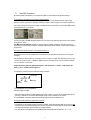
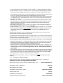
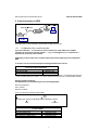
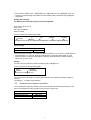
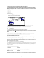
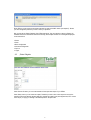
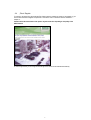
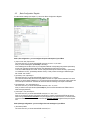
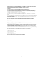
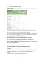
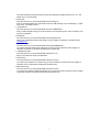
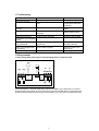
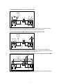
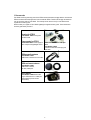
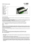
Manual
Page 1-34
Telic STD 32
Telic GmbH – Internet: www.telic.de; E-mail: [email protected]
Version 03/09
1
Introduction.............................................................................................................................................3
Attention, please read this .................................................................................................................4
2
Background Information ..........................................................................................................................4
2.1
GSM-Network in general....................................................................................................................4
2.2
GPRS ...............................................................................................................................................5
2.3
Quadband Frequencies .....................................................................................................................5
2.4
Internet in general .............................................................................................................................5
2.5
E-mail via SMTP................................................................................................................................5
2.6
Web Server.......................................................................................................................................5
2.7
Fixed IP ............................................................................................................................................6
3
Operating Conditions...............................................................................................................................6
4
Proper Use .............................................................................................................................................6
5
Introduction.............................................................................................................................................7
6
Quick start-up .........................................................................................................................................8
6.1
General preparations.........................................................................................................................8
6.2
Hardware preparations ......................................................................................................................8
6.3
Configuration Call..............................................................................................................................8
6.4
Quick configuration check..................................................................................................................9
7
Table of SMS Commands........................................................................................................................9
7.1
Send SMS Commands ....................................................................................................................10
A configuration command should look like the following example:....................................................................10
7.2
Explanation of the commands..........................................................................................................10
7.3
Examples for SMS Commands ........................................................................................................11
8
E-mail functionality via GPRS ................................................................................................................12
8.1
Configuration of the e-mail functionality............................................................................................12
8.2
Additional e-mail configuration possibilities.......................................................................................13
9
Access the STD32 from the internet.......................................................................................................15
9.1
Prerequisites...................................................................................................................................15
9.2
Registration to the web-server of the STD32 ....................................................................................15
9.3
„Status“-Register.............................................................................................................................16
9.4
„Photo“-Register..............................................................................................................................17
9.5
„Basic Configuration“-Register .........................................................................................................18
9.6
„Advanced Configuration“-Register ..................................................................................................20
9.7
„Clip List“-Register...........................................................................................................................24
9.8
„Logout“-Register ............................................................................................................................24
9.9
Detailed example.............................................................................................................................24
9.10 Configuration via SMS.....................................................................................................................25
9.11 Configuration via web interface........................................................................................................25
10
Connecting the camera.......................................................................................................................27
11
Troubleshooting .................................................................................................................................28
12
Wiring examples.................................................................................................................................28
13
Accessories .......................................................................................................................................30
14
Technical data....................................................................................................................................31
15
Document history ...............................................................................................................................31
16
Annexe ..............................................................................................................................................33
1.1
2
1 Introduction
Thank you very much for purchasing our Telic STD32 telemetry device!
The STD32 offers the user the possibility to remotely switch ON or OFF electronic devices and to receive alarm
messages via (SMS). You can switch devices either with an SMS or using a simple voicecall. Alarm messages
(SMS) can be received with any mobile phone supporting SMS functionality.
With the new generation of the STD32 you now also have the possibility to recieve alarm messages via e-mail.
With the help of the digital camera which is available as an accessory, pictures can be taken and sent via e-mail
triggered by an alarm.
The STD32 has an integrated webserver which allows direct access to the device via the internet and a standard
webbrowser (e.g. Internet Explorer or Firefox) from a computer or a mobile phone with web functionality. Thus it
is very simple to switch electrical devices remotely and to change the configuration of the STD32 from
anywhere.
We wish you success and joy in using your new STD32!
Concerning the user manual:
This user manual is the extended version of the printed booklet which is part of the delivery package.
This document describes additional features and possible new applications where the STD32 could be
used.
This document is meant to help you use the various functions of the device in the most optimal way. Therefore
we ask you to please read this manual carefully.
If you are in a hurry and want to make yourself familiar with the details of the product later, then please read
chapter 6 “Quck Start-up” first.
There you will find all necessary information to put the device into operation.
The information in this document has been gathered after thorough inspection but they are not be taken as
assurance of end product properties.
The written approval of Telic GmbH is mandatory before you can pass on or reproduce this documentation for
this product or the software or use the content.
Telic reserves the right to change the data mentioned here without prior notice and does not take any
responsibility for technical inaccuracies and/or omissions. This manual has been thoroughly checked; should
you nevertheless find an error or want to express criticism or make suggestions, please send an e-mail to
E-mail: [email protected]
Oberhaching, 23rd. March 2009
© 2009 Telic GmbH, Oberhaching, Germany
3
1.1Attention, please read this
This user manual contains important information for startup and use of the STD32. Read it carefully before you
start working with the STD32.
The warranty will be null and void should damage occur due to non-compliance with these instructions for use.
We cannot accept any responsibility for consequential loss.
We cannot be held responsible for material loss or personal injury that is due to incompetent use or noncompliance with the safety instructions. The warranty will be null and void in such circumstances.
The STD32 contains highly integrated components which can be damaged by electrostatic discharge.
Therefore only touch the STD32 on the edges and avoid to touch the pins of components on the
board.
During the operation of the STD32 it can happen that SMS messages will be sent out automatically or that
GPRS connections will be built up which will generate costs similar to those of your mobile phone. Your mobile
network provider will invoice those costs to you.
Safety Instructions
When using products which are exposed to electric voltage the valid VDE-regulations have to be
observed. Especially VDE 0100, VDE 0550/0551, VDE 0700, VDE 0711 and VDE 0860 are
applicable.
All wiring work has to be done in a voltage free state only
All cables and wires which are energized and connected to the device, the module, or components have to be
checked regularly for any damage to the isolation shielding or fractures in the cables. If the supply cables are
visibly damaged the device has to be taken out of operation immediately until the faulty cable has been
exchanged
Before putting a device into operation, it has to be clarified, whether this device or module is appropriate for
the field of application. In case of doubt ask a specialists or the manufacturer of the device.
Please note that we are not responsible for any errors in usage or connection. Therefore we cannot accept
any responsibility for consequential loss.
Before opening the device always disconnect the mains adapter or make sure that the device is disconnected
from the power supply.
Components, modules or devices have to be built into a housing before they are put into operation. During
installation they should not be connected to any power supply .
You should only use tools on components, modules, or devices if they are disconnected from the power
supply, and residual electric charge (which may still be stored in some components inside the device) has
been discharged.
When using components or modules it is necessary to strictly observe the specification given in the
corresponding description of these components.
If a description for a private end-customer does not clearly state which electric data is valid for a component or
a module, how to wire the device, which external components, or additional devices can be connected or
which parameters these components are allowed to have, a specialist must be contacted.
Devices which operate with greater than 35 Volts have to be connected by a specialist.
Before putting the device into operation it should be checked that there is no current leakage on the housing.
In case that measurements with the opened housing are necessary, an isolating-transformer has to be
integrated for safety reasons. Alternatively the voltage can be supplied by an appropriate power supply which
complies with the safety regulations. All wiring work has to be done in a voltage free state only.
2 Background Information
2.1GSM-Network in general
The GSM Network (Global System for Mobile Communications) is a standard for all-digital mobile phone
networks. GSM has been created to provide a mobile telephone system offering the users europewide mobility
and voice services compatible with ISDN or analog services.
4
Originally GSM has been designed for voice calls, the tramsmission of text messages (SMS) and the
transmission of data with a constant data speed. With the success of the internet an evolution of GSM startet.
The GSM network was expanded to offer packet oriented data transmission (e.g. via GPRS) while keeping all
other features and being fully downwards compatible.
2.2
GPRS
GPRS (General Packet Radio Service) is a packet oriented transmission service which is used in the mobile
networks and which is supported by almost all network providers.
With GPRS you only have a virtually existing permanent connection to the other party. Only when you really
transmit data will the channel will be used, otherwise it is free for other users. This means that no channel will be
reserved permanently for a user (as it is with a GSM voice call). Therefore the GPRS-bills depend more on the
actual data volume transmitted than on the connect time.
If the device is booked into the GPRS-Net it will automatically be assigned an IP-Address and can exchange
data with any server accessible via the internet,
Before you can use the GPRS-Interface the SIM-Card must be activated for GPRS. To order this functionality
please talk to your mobile network provider.
2.3Quadband Frequencies
When a device is “quadband” it means that it uses the four major GSM frequencies and that it is compatible with
most GSM networks worldwide.
These four frequencies are 850 MHz and 1900 MHz (on the American continent) and 900 MHz and 1800 MHz,
which are used in almost all other countries worldwide (Europe and Asia).
In contrast to a triband mobile phone which only supports 900/1800 and 1900 or 850/1800 and 1900 a
quadband device can be used in almost every GSM network worldwide.
2.4Internet in general
The internet is today a worldwide network consiting of many computer networks to enable the exchange of data.
It offers the use of internet services such as wwww, e-mail, FTP or VoIP (voice call).
In theory every computer can be connected to any another computer in the world. The data exchange between
the internet computers is handled with the standardized internet protocol (IP).
2.5
E-mail via SMTP
SMTP (Simple Mail Transfer Protocol) is a method used to send e-mails over the internet. The handling will be
done by a mail programme, which is running in this case on the STD32 and which supports SMTP. For the user
this process is invisible. This programme establishes a connection to a SMTP server which will transport the email to the given e-mail address with the help of further SMTP-servers if necessary.
To be able to use this service you must have an e-mail account with a mail provider (e.g. AOL or Yahoo) and the
following settings have to be made which are different for every mail provider (e.g. AOL or Yahoo).
Name of the SMTP Server (e.g. smtp.mailprovider.com or 192.168.234.12)
User name to register to the SMTP Server
Password to register to the SMTP Server
On our Telic website www.telic.de you can find a list of the approved e-mail providers which we have tested.
To see which settings have to be used on the STD32 to be able to take advantage of this service please read
chapter 8.
2.6
Web Server
A webserver
is a programme which runs on a device (the so called server) that sends data and documents to
clients (standard webbrowsers such as Internet Explorer or Firefox). Webservers are mainly used as wwwservice in the internet. The data and documents can be retrieved and read from any computer connected to the
internet worldwide.
Such a webserver has also been implemented on the STD32. To use this function several particularities have to
be observed. You can find more detailed information in chapter 9.
5
2.7
Fixed IP
IP-Addresses are used in computer networks based on the internet protocol (IP) to transport data from the
sender to the addressee. The internet is an example of such a computer network.
To be able to address a webserver the IP-address must be known in order to allow the webbrowser to
download data from that webserver and show it to the user. Therefore servers usually always have an IP
address which stays the same (fixed IP address)
The most common notation of the IP addresses used today consists of four figures, between 0 and 255, which
are separated by a colon, e.g. 127.0.0.1.
To be able to use the webserver on the STD32 the mobile network provider must assign a fixed IP address to
the device and allow it a connection to the internet. This function is typically available on request only or with
special GSM network providers.
3 Operating Conditions
Operate the STD32 only with a supply voltage between 5-32V DC and have in mind the polarity! (see
picture1) Use a stabilized power supply with minimum 1A output current. (we recommend to use only the
original Telic power supply). If you use a mains adapter for power supply it has to conform with the VDE
regulations.
Devices with an operating voltage greater than 35 Volts which are connected to the relay have to be installed
by a specialist observing the VDE regulations.
Loads connected to the device are not allowed to exceed 1000 W per relay.
The maximum voltage is 250 VAC (alternating current)
The maximum switching power per relay is 6 A (depending on the width of the PCB tracks)
When installing the device make sure that the supply cable has a sufficient diameter
During operation the temperature has to be between -20° and 55° Celsius.
The device is meant for operation in dry and clean rooms only.
Protect the device from humidity, spray water and heat.
In case of condensation allow a period of about 2 hours for acclimatisation.
Do not operate the device in areas where inflammable gas, vapours, or dust are or could be present.
Do not expose the device to heavy vibrations.
The unit may only be repaired by a specialist.
Only original parts have to be used when repairing the unit. The use of differing spare parts can cause serious
material loss or personal injury.
Keep the device away from flower vases, bath tubs, washbasins, liquids etc.
No special operation position of the device has to be observed.
4 Proper Use
The device is designed for the remote switching of devices via the GSM network as well as the remote retrieval
of status information of the inputs and the generation of SMS messages or e-mails after status has changed at
the inputs. A different utilisation of the device other than the one described above is not allowed.
6
5 Introduction
The STD32 is a telemetry module which is easy to install and simple to use.
With the STD32 you can control two relays and monitor the status of two digital inputs with one or several
common mobile phones.
Apart from the STD32 you only need a valid SIM Card of any network provider (GSM850 / 900 / 1800 or 1900
MHz)
While using prepaid SIM-cards one shall always keep aware of the amount of remaining credit left on the card,
so that in case of alarms a message can be sent.
Typical fields of application are
the opening of (garage) doors
switching on and off light and alarm devices as well as generating alarm messages (SMS or e-mail)
the retrieval of information from door sensors, movement sensors or level sensors
etc.
You can for example open your garage door with a call or get a message (viaSMS or e-mail) in case your house
alarm system gets triggered. In connection with the Telic camera you can get a photo via e-mail when a
movement sensor connected to the STD32 detects movement.
Relay
1
Relay
2
IN2
ANT
IN1
P
W
R
PWR
STD32
Relay1/2 IN2
IN1
User
name
L1 L2 L3 L4
GSM
Module
C
A
Camera GSM M
LED LED E
R
A
Status LEDs
Web-Server LED
System LEDs
Abb. 1
As described in figure 1 the STD 32 has five pairs of screw terminals. Two pairs (In1, In2) are inputs to two
optocouplers. Two pairs (Relay1, Relay2) are outputs (switches) of the 2 relays of the STD32.
Connect the supply voltage of the STD32 on connector PWR or on the screw terminal pair.
ANT: connect the GSM antenna with FME-female connector here.
LED Signals:
When the engine is booked into the GSM network the GSM LED flashes once every 2 seconds.
The status LEDs show the status of the inputs and outputs. L1 and L2 are on if the corresponding relay is
activated. L3 and L4 signal the status of the optocoupler inputs IN1 and IN2.
The camera LED is on as long as the camera is active.
The Web-Server LED is blinking when the web-server is active.
The system LEDs show the current system status and are described later on.
Please observe the maximum output voltage of the relays and the maximum input voltage of the inputs! In
chapter 3. “Operating conditions” you will find further information on this.
7
6 Quick start-up
In the following section it is described step by step what you have to do to administrate the STD32 without long
preparation.
6.1General preparations
You need an activated SIM card of a GSM network provider. The PIN of this card has to be set to “0000”(4 times
zero).
Alternatively you could use the PIN “2468”. To change the PIN you can use a common mobile phone. The
instructions how to change the PIN are described in the manual of your mobile phone.
If you use a SIM card with a PIN different from “0000” or “2468” in the STD32, the STD32 will use a
“wrong” PIN. After the second attempt to power up the device your SIM card will be blocked. In this case
you need to use the “Super-PIN” or “PUK” to assign a new PIN to your card. Please look into the user
guide of your mobile phone. There you find how to use the PUK to de-block the SIM card.
Should you wish to use a SIM card which does not require a PIN, this is also possible and the STD32
recognizes this and will behave accordingly.
In the following we will refer to the “master mobile” as the mobile telephone which you want to use to switch the
outputs and to configure the STD32 via calls.
To be able to administer the STD32 with your master mobile it is necessary that the “incognito” or “private call”
function of the mobile is deactivated. This means the master mobile has to transmit the mobile telephone
number with every call. To change the settings please refer to the user guide of your mobile telephone.
To test the setting you can call a different mobile phone; there your phone number or name should be displayed.
6.2 Hardware preparations
Before connecting the supply voltage to the STD32 please insert the SIM card into the SIM card holder on the
backside of the STD32: To open the SIM card holder move it sideways and flip it open; insert the card (mind the
proper orientation of the card) and close it again. To lock it in place move the top sideways in the opposite
direction.
Now please connect the GSM antenna which is part of the delivery to the proper antenna connector on the
STD32 board.
After that connect the power supply (either via the connector or via the pair of screw terminals, never use both
options at the same time)
Please always observe the polarity (see picture 1) and that you have a proper power supply. (see
chapter 3.“Operating Conditions”)
6.3 Configuration Call
After having connected the power supply the green system LED will be illuminated for approx. 5 seconds
(system start). Shortly after that the GSM LED will be activated. Now the STD32 will automatically try to connect
to the GSM network. As soon as this is done, the GSM LED will be flashing once every 2 seconds.
As soon as the red and green system LED are toggling the STD32 is ready and waiting for the configuration.
Now call with master mobile the phone number of the SIM card which is inside the STD32. The STD32 will
accept the call and cancel it a few seconds later. During this call, a four digit DTMF sequence is sent to the
caller and you will hear them on your mobile phone.
With this call the STD32 is configured to the master mobile.
Pay attention:
As long as the STD32 still has the factory defaults it shows this by the toggling the red and green system LEDs.
From this moment on you have three minutes to configure the STD32 with the configuration call.
After 3 minutes (without configuration call done in between) the device switches off. If you switch it on again
afterwards the STD32 is again expecting the configuration.
8
In case the STD32 will be disconnected from the power supply after a successful configuration by a power
failure it will automatically send a SMS/E-mail with the text “START-UP ALARM” to the preconfigured telephone
number as soon as the power supply is established again.
6.4 Quick configuration check
To check whether the configuration was successful you can now make the following quick configuration check.
Take your master mobile and call the telephone number of the SIM-Card inside the STD32. This call should be
cancelled by the STD32 and the Relay 1 should switch for one second (watch LED L1 to see the status of the
relay).
Now the basic configuration is done which means that all future events will be sent to the master mobile and that
Relay 1 can be switched from that mobile phone.
To use the additional functions of the STD32 please continue reading chapter 7 “Table of SMS commands”
7 Table of SMS Commands
Factory settings
Status of I/Os
Start-up alarm SMS on/off
Activate web-server
Relay 1 on
Relay 1 off
Relay 2 on
Relay 2 off
Switching time Relay 1
Switching time Relay 2
Delay before reply (Relay 1)
Delay before reply (Relay 2)
Time of activation Input 1
Time of activation Input 2
Invert Input 1
Invert Input 2
2nd alarm number
3rd alarm number
4th alarm number
5th alarm number
new password
event text 1
event text 2
Start-up alarm Text
add clip to the extended clip list
remove clip from the extended clip list
R:
ST?
S:1. / S:0.
WEB:1.
O1ON.
O1OFF.
O2ON.
O2OFF.
O1:xxxxx. (seconds)
O2:xxxxx. (seconds)
A1:xxx. (seconds)
A2:xxx. (seconds)
I1:xxx. (seconds)
I2:xxx. (seconds)
V1:x. (x= 1/0 )
V2:x. (x= 1/0 )
C2:<number>.
C3:<number>.
C4:<number>.
C5:<number>.
PN:xxxx.
E1:<text>.
E2:<text>.
PT:<text>.
CL:<nummer>.
CD:<nummer>.
9
7.1
Send SMS Commands
By sending a SMS to the STD32 you can switch the outputs or make individual configuration settings.
Those SMS have the following format which is described below:
In order to avoid unauthorized usage, every configuration command to the STD32 must start with a 4-digit
password. Control commands (for example: switching an output or status requests) do not require a password.
The factory set password is the last four digits of the IMEI number of your STD32. You find YOUR IMEI number
on the GSM module of your STD32.
The last four digits of the IMEI being the password for your device must always be kept a secret. In this example
the keyword is “4244”.
The IMEI cannot be changed! Although the password can be changed if needed for security purposes, you
should keep in mind that every command – including setting back to factory settings – requires the knowledge of
the password.
All commands (except R: and ST?) must end with a full stop “.”!
All commands can be sent in one SMS; each command has to be separated from the next by a full stop (see
examples).
The parameters for the seconds e.g. command “O1:xxxxx.” can have 1-5 digits. Valid parameters are e.g. 1 (for
1 second), 90 (for 90 seconds) or 99999 for (99999 seconds). No leading “zeros” have to be added. Example:
“O1:110” stands for 110 seconds.
Please observe the difference between the figure ‘0’ and the letter ‘O’!. (“O1ON.” contains twice the
letter O; “V1:0.” contains once the figure 0)
A configuration command should look like the following example:
Output1
55 seconds
4244 O1:55.
4-digit
keyword
space
full stop
7.2 Explanation of the commands
Switching outputs via SMS
After the STD32 has received a SMS with the text “O1ON.” (Output 1 ON) from the configured mobile phone,
the relay 1 switches for one second. With the SMS “O2ON.” relay 2 switches for one second.
To get feedback of the actual status of the inputs and outputs just send a SMS with “ST?”
Configuration-SMS (attention 4-digit keyword required!)
The SMS “R:” is sets the STD32 back to the factory settings. Please note that this SMS can be sent from any
mobile phone as long as the 4-digit keyword is known. This ensures that the STD32 can still be used even if
the original master mobile (phone number) is no longer available.
You can activate or deactivate the Start-up SMS (START-UP ALARM) with the SMS “S:x.” (x = 1 or 0).
10
To activate the web-server send a SMS with the command “WEB:1:”, to deactivate the webserver “WEB:0:”
A SMS with the text “O1:xxxxx.” or “O2:xxxxx.” (xxxxx = seconds) configures the switching time of the relays.
The STD32 saves these settings so that they are still available after the supply voltage has been restored.
If the switching time has been set to 0 by a configuration SMS the corresponding relay switches permanently
at every call. If the relay has been active before it will afterwards be inactive and vice versa.
In this case a SMS with the text “O1ON.” from the configured mobile phone switches the relay 1 permanently
on. A SMS with “O1OFF.” permanently switches off relay 1. Relay 2 reacts accordingly to SMS messages
with “O2ON.” and “O2OFF.”.
The SMS “A1:xxx.” or “A2:xxx.” (x = seconds) sets the delay after which a reply SMS is sent after an output
has been activated. This can be helpful if you want to switch something on or off and would like to measure
the result of this output control with one of the inputs of the STD32. Therefore the new status after the
switching of the output is transmitted.
With a SMS containing the text “I1:xxx.” or “I2:xxx.” (xxx = seconds) you can configure the time the inputs
have to be activated before the STD32 sends out an alarm SMS
A SMS with the text “V1:x.” or “V2:x.” (x = 1 or 0) can change the polarity of the inputs. If x=1 an alarm SMS
will be sent in case the input has not been activated for the configured time. The default value is x=0 which
means that the STD32 will send an event alarm in case the input has been activated longer than the
configured time.
Please note that the brackets “<“ and “>“in the following commands are not part of the commands but are
inlcuded in order to increase the readibility of the overview!
Four additional alarm numbers (mobile phones) can be defined using C2: - C5: commands. These numbers are
allowed to set relay 1 by a call and they are informed via SMS in case of Start-up or events. These numbers are
not allowed to send configuration SMS messages.
If an alarm number is given in international format, the number must start with ‘+’. (e.g. +491721234567)
With the “PN:<4digit password>.” command the password can be changed. The password can include letters
and figures but no special characters are allowed. All letters have to be in capital. The standard password
(factory setting) is the last 4 digits of the IMEI (see chapter SMS Commands).
The texts of the event or start-up SMS can be changed with the commands “E1:<text1>.”, “E2:<text2>.” and
“PT:<startup text>.”. The message length must not exceed 64 characters. Do not use command syntax
inside a message text. The ‘.’ is the terminating character of the text. Each new text must be sent in a
separate SMS.
You can generate an extended clip list of 500 clip numbers. The numbers stored in the clip list are allowed to
switch relay 1 with a phone call. Use “CL:” to generate the clip list and add further phone numbers. With “CD:”
you can delete a phone number from the list. Be aware that you cannot read out the clip list (getting SMS
messages) because it could by far exceed the size limitation of SMS texts.
Please note that all commands listed in the section “Configuration SMS” require the 4-digit keyword at the
beginning.
7.3
Examples for SMS Commands
Please note that for these examples the 4-digit password 4244 has been chosen. Instead of this
password you have to use your 4-digit password of your STD32!
Start-up alarm off, relay 1 on, relay 2 off, time of activation of input 1: 5 sec.:
4244 S:0.O1ON.O2OFF.I1:5.
4244 O1:90.
Switching time of relay 1 = 90 seconds:
4244 R:
Reset settings to factory settings:
4244 C2:+491721234567.
Configuration of the second alarm number:
4244 C2:.
Deleting a alarm number:
4244 PN:AB12.
Configuration of a new password:
4244 CL:+491721234567.
Adding a new clip to the extended clip list:
11
4244 CD:+491721234567.
Removing the clip from the extended clip list:
8 E-mail functionality via GPRS
The STD32 offers you the possibility to get messages via SMS and via e-mail.
8.1
Configuration of the e-mail functionality
If you need a full stop "." in a parameter as it is for example in an e-mail address, the complete
parameter has to be put into inverted commas (“...”) (e.g. "[email protected]"), as otherwise the "."
would be seen as the end of the command.
Additionally you have to take care to send the 4-digit keyword at the beginning of each configuration
SMS.
To be able to use the e-mail functionality the following parameters have to be set.
GPRS settings
(to set up an internet connection)
Name of the APN (Access Point Name)
APN:<text>.
User name for APN
APNUSR:<text>.
Password for APN
APNPWD:<text>.
With the commands “APN:<text>.”, “APNUSR:<text>.” and “APNPWD:<text>.” you make the basic settings to
build up a GPRS (internet) connection. You need to get the necessary data from your GSM network provider
Example (Vodafone, Germany):
The GSM network provider Vodafone gives you the following details:
APN: web.vodafone.de
User: vodafone
Password: vodafone
Thus you would have to send the following SMS:
Username
4244 APN:"web.vodafone.de".APNUSR:vodafone.APNPWD:vodafone.
APN
SMTP settings
(to send e-mails)
IP- Address of the SMTP Server
Port of the SMTP Server
User name for SMTP Server
User password for SMTP Server
Password
SMTPIP:<text>.
SMTPPORT:xxxxx.
SMTPUSR:<text>.
SMTPPWD:<text>.
12
The commands “SMTPIP:<text>.”, “SMTPPORT:xxxxx.”, “SMTPUSR:<text>.” and “SMTPPWD:<text>.” are
necessary to make the settings on the SMTP server side. Please contact your SMTP provider regarding the
required data.
Example (AOL, Germany):
The SMTP server provider AOL has given you the following details:
Server name: smtp.de.aol.com
Server port:25
User name: Hans.Muster
Password: Muster
Thus you would have to send the following SMS:
4-digit
IPUsername
Password
Port
password
Address
4244 SMTPIP:"smtp.de.aol.com".SMTPPORT:25.SMTPUSR: "Hans.Muster". SMTPPWD:Muster.
Specific settings:
Recipient for e-mail transmission
Recipient e-mail address
TO:<text>.
With the command “TO:<text>.” you define the recipient e-mail address. You can list up to 5 e-mail addresses
each separated by a <;>. The max. length per e-mail address is 75 characters. Default status: no e-mail
address is entered. If at least one e-mail address is defined an e-mail transmission is started at following
events: start up, input1, input 2.
Example:
You want to send an e-mail after an Event to the address [email protected].
Thus you would have to send the following SMS:
4-digit
password
RecipientE-mail Address
4244 TO:"[email protected]".
If you do not want to send further event e-mails please delete all e-mail recipients by sending an “empty” TO
command
e.g. 4244 TO: "". to delete all e-mail addresses
8.2
Additional e-mail configuration possibilities
You can make further configuration settings for the e-mail functionality. With the following commands you can
define e-mail recipients who should only get an e-mail in case of a certain event.
Event 1 (Input1)
Recipient e-mail address
Subject line of the e-mail
Body of the e-mail
TO1:<text>.
SUB1:<text>.
BODY1:<text>.
13
Event 2 (Input2)
Recipient e-mail address
Subject line of the e-mail
Body of the e-mail
Start Up Event
Recipient e-mail address
Subject line of the e-mail
Body of the e-mail
Incoming Call Event
Recipient e-mail address
Subject line of the e-mail
Body of the e-mail
Photo SMS Event
Recipient e-mail address
Subject line of the e-mail
Body of the e-mail
TO2:<text>.
SUB2:<text>.
BODY2:<text>.
TO3:<text>.
SUB3:<text>.
BODY3:<text>.
TO4:<text>.
SUB4:<text>.
BODY4:<text>.
TO5:<text>.
SUB5:<text>.
BODY5:<text>.
With the command “TOx:<text>.” (x = 1 to 5 see above) you define the recipient e-mail address (only
for this event). You can list up to 5 e-mail addresses each separated by a <;>. The max. length per email address is 75 characters. Default status: no e-mail address is entered.
With the command “SUBx:<text>.” (x = 1 to 5 see above) the subject line of the e-mail is defined. The
max. length is 128 characters per text. The default value is "STD32 x event"
You can define the body text of the e-mail with the command “BODYx:<text>.” (x = 1 to 5 see above).
The max. length is 160 characters per body text. The default value is empty, meaning no text is sent.
Additional settings
Senders e-mail address
Priority of the e-mail
E-mail as HTML or Text
E-mail code
Sender in subject line
Send attachment
E-mail address in CC
E-mail adress in BCC
Request picture via SMS
Activate camera (on/off)
FROM:<text>.
PRIO:<x>.
HTML:<x>.
CHARSET:text>.
FROMSUB:text>.
ATT:<x>.
CC:<text>.
BC:<text>.
PHOTO.
CAM:<x>.
With the command “FROM:<text>.” you can configure the sender e-mail address. The max. length is 75
characters. The default value is [email protected]
“PRIO:<x>.” sets the priority with which the e-mail will be displayed. Possible values are from 1 to 5.
The default value is 3 (normal priority).
With the command “HTML:<x>.” you can define whether the e-mail should be sent as a HTML message or as
a text message (1 = HTML and 0 = text). The default value is 0.
With the command “CHARSET:text>.” you indiicate with which coding the e-mail will be sent. The default
value is "UTF-8". Normally you do not have to change this.
If you want to enter the sender into the subject line you have to send the command “FROMSUB:text>.”. The
max. length is 75 characters. No senders e-mail address is entered here as default value.
With the command “ATT:<x>.” you can configure whether an attachment should be send or not (1 = send
attachment, 0 = no attachment). The default value is 1 (send attachment).
If you want to put a recipient on CC (Carbon Copy) you can do this with the command “CC:<text>.”. The max.
length is 75 characters. No e-mail addresses are entered as a default value.
To put a recipient in BCC (Blind Carbon Copy) use the command “BC:<text>.”. The max. length is 75
characters.. No BCC e-mail addresses are entered as a default value
14
To make a picture and send it via e-mail send the SMS command “PHOTO.“.
You can deactivate the camera functionality when the camera is connected to the STD32 with the command
“CAM:0.“ and activate it with “CAM:x.“. The camera offers different resolutions and you can select the desired
camera resolution (x):
1 = 80 x 60
3 = 160 x 120
5 = 320 x 240
7 = 640 x 480
The default value is 7.
9 Access the STD32 from the internet
The web-server implemented in the STD32 allows you to set the outputs of the device and to make
configurations from anywhere in the world with the help of a web interface and the internet.
9.1
Prerequisites
To be able to use this functionality you need a special type of SIM-Card:
You need a fixed IP address and the GSM network provider has to allow access to that IP and from the
internet.
Furthermore you have to make the GPRS settings from chapter Fehler! Verweisquelle konnte nicht
gefunden werden. to allow that the STD32 to establish a connection to the internet.
Please ask your GSM network provider for help.
After that you have to activate the web-server on the STD32 with a SMS command. Therefore please
send the following SMS to the STD32: “WEB:1.“(s. chapter 7)
Please verify now on the STD32 whether the orange system LED (see picture 1 in chapter 5) is blinking. This
LED shows that the web-server is activated.
9.2
Registration to the web-server of the STD32
If your SIM card fulfils all the above requirements and if your GPRS settings have been correct you can access
the IP address of your SIM card and register with the help of a standard web-browser (e.g. Internet Explorer or
Firefox) to your STD32.
Your IP address might look like this example:
87.139.101.192
(Example)
Enter your IP address in the address line of your web-browser in the following format:
http: //87.139.101.192
(Example)
After entering your IP address in your web-browser you will be asked to enter your user name and password.
15
Enter “STD32“ as user name and as password the last four digits of the IMEI number (see chapter 7). Should
you have changed the password you have to enter your password.
Now you will see the “Status“-Register of the STD32 web-server. This user interface is always in English. All
available functions are described in detail in the following. Each chapter handles one of the registers displayed
on the web-surface:
Status
Photo
Basic Configuration
Advanced Configuration
Clip List
Logout
9.3
„Status“-Register
Under “Device I/O status“ you can control the status of the inputs and outputs of your STD32.
Under „Relay control“ you can switch the outputs. Therefore you have to click on the drop-down menu of the
respective output and select the desired state (ON = activate the output for the preconfigured time; OFF = switch
of the output). To apply your settings to the STD32 press the “Accept“ button.
16
9.4
„Photo“-Register
To retrieve a new picture from the connected Telic Camera which is available as accessory (see chapter 13) you
have to select the “Photo“-Register and press the “Load“-button. How to connect the camer is described in
chapter 10.
Please note that the transmission of the picture may take some time depending on the quality of the
GPRS network.
In case the light intensity is not enough the infrared light of the camera will be activated automatically.
17
9.5
„Basic Configuration“-Register
To make all basic settings (see chapter 7.1) click on the “Basic Configuration“-Register.
Under „I/Os configuration “ you can configure the inputs and outputs of your STD32.
„Output 1 time“ and „Output 2 time“:
This is the same as if you would send the SMS command „O1:xxxxx.“ or „O2:xxxxx.“
Here you set the switching time (in seconds) of the relays.
If the switching time has been set to 0 by a configuration SMS the corresponding relay switches permanently
at every call. If the relay has been active before it will afterwards be inactive and vice versa.
In this case a SMS with the text “O1ON.” from the configured mobile phone switches the relay 1 permanently
on. A SMS with “O1OFF.” permanently switches off relay 1. Relay 2 reacts accordingly to SMS messages
with “O2ON.” and “O2OFF.”.
„Input delay 1“and „Input delay 2“:
This is the same as if you would send the SMS command „A1:xxx.“ or „A2:xxx.“
This command sets the delay after which a reply SMS is sent after an output has been activated. This can be
helpful if you want to switch something on or off and would like to measure the result of this output control with
one of the inputs of the STD32. Therefore the new status after the switching of the output is transmitted.
„Input debounce 1“ and „Input debounce 2“:
This is the same as if you would send the SMS command „I1:xxx.“ or „I2:xxx.“
Here you define for the inputs the time (in seconds) they have to be activated before the STD32 sends an
alarm message (debounce).
„Invert Input 1“ and „Invert Input 2“:
This is the same as if you would send the SMS command „V1:x.“ bzw. „V2:x.“
Here you can invert the reaction of the inputs of the STD32. If „inverted“ is selected the STD32 will send an
alarm if the input has not been activated for the preconfigured time. The default value is „not inverted“ which
means the STD32 sends an event alarm in case the input has been activated longer than the preconfigured
time.
Under „Message configuration“ you can configure the event messages of your STD32.
„Send start-up SMS”:
This is the same as if you would send the SMS command „S1:x.“
18
Here you can switch on or off the Start-SMS (START-UP ALARM). You only have to click on the drop-down
menu and selected the desired value (ON = will be sent; OFF = will not be sent)
„Password”:
This is the same as if you would send the SMS command „PN:<4-digit password>.“
This command changes the password of the STD32 The password can include letters and figures but no
special characters are allowed. All letters have to be in capital. The standard password (factory setting) is the
last 4 digits of the IMEI (see chapter SMS Commands).
„Message 1 text” and „Message 2 text“ or „Power-up message text“:
This is the same as if you would send the SMS commands „E1:<text1>.“, „E2:<text2>.“ and „PT:<startuptext>.“
You can change the texts of the Start-up alarm and event SMS with these commands. Do not use command
syntax inside a message text. The ‘.’ is the terminating character of the text. The message length must
not exceed 64 characters.
Under „CLIP configuration“ you can configure the important Telefone numbers of your STD32.
„Master mobile“:
Here you enter the phone number of the master mobile telephone.
„Clip 2 mobile“,„Clip 3 mobile“,„Clip 4 mobile“,„Clip 5 mobile“:
This is the same as if you would send the SMS command „C2:<nummer>.“, „C3:<nummer>.“
,„C4:<nummer>.“,„C5:<nummer>.“
Here you can enter up to four additional alarm numbers (=mobile phones) which should receive also the startup alarm and event SMS. These phone numbers are also allowed to switch relay 1 via call but they cannot
change the configuration of the device via SMS (C2:–C5:).
In case the alarm numbers are entered in international format they have to start with ‚+’ (e.g. +491721234567)
Under „Web authorization“ you can configure the access data for the web interface
„Web access user name“
Here you change the user name
„Web access password“
Here you change the password
At the end you have to confirm your settings with the „Accept“-Button.
19
9.6
„Advanced Configuration“-Register
To make the additional configuration settings (as described in chapter 8.2) you have to click on the „Advanced
Configuration“-Register.
In the upper part of the „Advanced Configuration“-Register you can change the GPRS and e-mail settings.
Under „Network configuration“ you can make the GPRS settings of your STD32.
This is the same as if you would send the SMS command „APN:<text>.“, „APNUSR:<text>.“ , „APNPWD:<text>.“
These are the basic settings to build up a GPRS (internet) connection. Enter the name of your APN in „APN“,
the user name in „User name“ and the password in „Password“.
Your GSM network provider will give you the necessary data you need.
.
Under „SMTP configuration“ you can make the SMTP (e-mail) settings of your STD32.
This is the same as if you would send the SMS command „SMTPIP:<text>.“, „SMTPPORT:xxxxx.“,
„SMTPUSR:<text>.“ and „SMTPPWD:<text>.“ .
Here you make the configuration settings of the SMTP server.
Enter your IP address of your SIM card at „IP address or domain“, the port at “IP Port“, your user name at „User
name“ and your password at „Password“.
Your SMTP service provider will give you the necessary data you need.
Under „E-mail configuration“ you can make the e-mail settings of your STD32.
„Recipients“:
This is the same as if you would send the SMS command „TO:<text>.“
You can list up to 5 e-mail addresses each separated by a <;>. The max. length per e-mail address is 75
characters. Default status: no e-mail address is entered. In case of the following events an e-mail will be sent:
Start Up, Input1, Input2, incomming call or when a camera picture is triggered via SMS or call.
„Priority“:
This is the same as if you would send the SMS command „PRIO:<x>.”
20
This command sets the priority with which the e-mail will be displayed. Possible values are from 1 to 5. The
default value is 3 (normal priority).
„HTML style“:
This is the same as if you would send the SMS command „HTML:<x>.“
Here you can define whether the e-mail should be sent as a HTML message or as a text message (1 = HTML
and 0 = text). The default value is 0.
„Characters set“:
This is the same as if you would send the SMS command „CHARSET:text>.“
Here you define with which coding you want to send the e-mail. The default value is "UTF-8". Normally you do
not have to change this.
„FROM field“:
This is the same as if you would send the SMS command „FROM:<text>.“
Here you can configure the sender e-mail address. The max. length is 75 characters. The default value is
[email protected]
„FROM field subject“:
This is the same as if you would send the SMS command „FROMSUB:<text>.“
If you want to enter the sender into the subject line you have to set this command. The max. length is 75
characters. No senders e-mail address is entered here as default value.
„Attachment file name“:
This is the same as if you would send the SMS command „ATT:<x>.“
Here you can mention the name of the attachment..
„Carbon Copy“:
This is the same as if you would send the SMS command „CC:<text>.“
If you want to put a recipient in CC (Carbon Copy) you can use the above command. The max. length is 75
characters. No CC e-mail address is entered here as default value.
„Blind Carbon Copy“:
This is the same as if you would send the SMS command „BC:<text>.“
If you want to put a recipient in BCC (Blind Carbon Copy you can use the above command. The max. length is
75 characters. No BCC e-mail address is entered here as default value..
21
In case you want to send some event messages only to certain e-mail recipients or if you want to
change the standard messages you can do this via the „Advanced configuration“- Register for the
individual events.
„Event 1 (input 1 event) e-mail“:
„Recipients for this event only (TO1)“
Here you define the recipient e-mail address (only for event 1). You can list up to 5 e-mail addresses
each separated by a <;>. The max. length per e-mail address is 75 characters. Default status: no email address is entered.
„Subject“
Here the subject line of the e-mail is defined. The max. length is 128 characters per text. The default
value is "STD32 1 event"
„Body“
You can define the body text here. The max. length is 160 characters per body text. The default value
is empty, meaning no text is sent.
„Event 2 (input 2 event) e-mail“:
„Recipients for this event only (TO2)“
Here you define the recipient e-mail address (only for event 2). You can list up to 5 e-mail addresses
each separated by a <;>. The max. length per e-mail address is 75 characters. Default status: no email address is entered.
„Subject“
Here the subject line of the e-mail is defined. The max. length is 128 characters per text. The default
value is "STD32 1 event"
„Body“
You can define the body text here. The max. length is 160 characters per body text. The default value
is empty, meaning no text is sent.
„Event 3 (startup alarm) e-mail“:
22
„Recipients for this event only (TO3)“
Here you define the recipient e-mail address (only for event 3). You can list up to 5 e-mail addresses
each separated by a <;>. The max. length per e-mail address is 75 characters. Default status: no email address is entered.
„Subject“
Here the subject line of the e-mail is defined. The max. length is 128 characters per text. The default
value is "STD32 1 event"
„Body“
You can define the body text here. The max. length is 160 characters per body text. The default value
is empty, meaning no text is sent.
„Event 4 (incoming call) e-mail“:
„Recipients for this event only (TO4)“
Here you define the recipient e-mail address (only for event 4). You can list up to 5 e-mail addresses
each separated by a <;>. The max. length per e-mail address is 75 characters. Default status: no email address is entered.
„Subject“
Here the subject line of the e-mail is defined. The max. length is 128 characters per text. The default
value is "STD32 1 event"
„Body“
You can define the body text here. The max. length is 160 characters per body text. The default value
is empty, meaning no text is sent.
After that you have to confirm your settings with „Accept“.
To set the STD32 back to factory settings please click on the register „Advanced Configuration“ and
then on „Reset“ at the bottom under„Misc configuration“.
Please note that this will delete all previously made configuration settings!
23
9.7
„Clip List“-Register
You can authorize up to 500 phone numbers to switch relay 1 via call.
„Add new CLIP“
This is the same as if you would send the SMS command „CL:<nummer>.“
Enter the phone number into the text field and confirm with the „Add“-button.
„CLIP list“
Under „CLIP list“ all phone numbers will be listed which you have added to the clip list.
In case you want to delete a phone number you only have to click on the „Delete“-button behind the respective
phone number. This is the same as if you would send the SMS command „CD:<nummer>.“
9.8
„Logout“-Register
After you have made all settings please click on „Logout“ to check out and to leave the web interface. Only then
you can be make sure that no unauthorized people make changes to your STD32 configurations.
9.9
Detailed example
You want to configure a STD32. The Output 1 should switch for 10 seconds after an incomming
call/SMS/internet command. Addtionally you want to authorize a telephone number in international format to
switch Relay 1 via SMS (+491721234567; example for a German phone number). Another phone number
(01529876543) should be allowed to switch Relay 1 via call.
In case of an alarm (Event 1 to 4) an e-mail should be sent to [email protected] and
[email protected].
You want that in case of Event 1 (and only then) an e-mail will be sent to [email protected].
The e-mail of Event 1 should look like this:
Subject: Stromausfall
Body: Kein Strom am Kühlschrank
Ihr GSM-Provider teilt Ihnen folgendes mit:
APN: web.vodafone.de
User: vodafone
Passwort: vodafone
Ihr SMTP-Anbieter teilt Ihnen folgendes mit:
Servername: smtp.de.aol.com
Serverport: 25
Username: Hans.Muster
Passwort: Muster
Das Passwort des STD32 (letzten 4 Stellen der IMEI) sei 4244
Die Telefonnummer des Administrator-Telefons: 0164 111 222 3
24
9.10 Configuration via SMS
1.SMS („Basic Configuration“)
4244 O1:10.C2:+491721234567.CL:01529876543.
2. SMS (GPRS settings)
4244 APN:"web.vodafone.de".APNUSR:vodafone.APNPWD:vodafone.
3. SMS (SMTP settings)
4244 SMTPIP:"smtp.de.aol.com".SMTPPORT:25.SMTPUSR: "Hans.Muster". SMTPPWD:Muster.
4. SMS (E-mail settings 1)
4244 TO: “[email protected]“.“[email protected]”.
5. SMS (E-mail settings 2)
4244 TO1: “[email protected]”.
6. SMS (E-mail settings 3)
4244 SUB1:Stromausfall.BODY1:Kein Strom am Kuehlschrank.
9.11 Configuration via web interface
Enter the IP address of your STD32 via standard web browser (e.g. Internet Explorer or Firefox) and register
yourself (see chapter 9.2)
Open the „Basic Configuration“-Register and make the following settings:
Confirm with „Accept“.
25
Open „Advanced Configuration“-Register and make the following settings:
Confirm with „Accept“.
26
Open „Clip List“ and make the following settings:
Click on „Add“
10 Connecting the camera
The STD32 is offers the possibility to monitor an object or a room with the help of the Telic camera optional
accessory for the STD32. You can retrieve an actual picture form the STD32 using any computer worldwide that
is connected to the internet(e.g. to check the weather conditions at your holiday home).
In addition a picture can be sent as an attachment to the preconfigured e-mail address in the case of an alarm.
This allows you to take further action if necessary (e.g. call the police if you see a burglar on the photo)
To be able to use this functionality you only have to connect the Telic camera to the camera plug on the STD32
(see picture 1).
After the software of the STD32 has recognized the camera the pictures can be viewed our sent via e-mail in the
following ways:
- Access of the web-browser through the internet and click on „Photo“-Register (see chapter 9.4)
- E-mail with JPEG attachment in alarm situation (see chapter 8.1)
- E-mail with JPEG attachment after incoming call (see chapter 8.2)
- E-mail with JPEG attachment after SMS request (see chapter 8.2)
In case the light intensity is not enough at the survey area the infrared light of the camera will be activated
automatically. Please note that due to the infrared light there will be a loss of colours in the picture.
The Telic camera has an adjustable sun shade (metal plate over the camera). Please take into consideration
when adjusting the sun shade that the insolation is changing during the day.
TIP:
To make sure that all desired objects will be in the picture, that the sun shade is in a good position
and/or that the illumination of the room will lead to satisfactory picture we recommend to take „test
pictures“ after the installation. Only then you can rely on the full functionaliy of the Telic camera.
27
11 Troubleshooting
Problem
GSM LED stays dark
GSM LED blinks twice cyclically
GSM LED blinks thrice
cyclically
GSM LED constantly on
GSM LED dies after 3 minutes
STD32 does not react on
configuration call (not accepting
the call)
STD32 does not react to a
configuration SMS
STD32 does not react to an
SMS, or call, although booked
to the network
System LEDs toggle
Possible Reason
No supply voltageNo SIM card / Improper contact with SIM
card
Solution
Connect power supply
Insert SIM card properly or
carefully clean contact area
of SIM card
PIN is not “0000”
Change SIM card’s PIN to
“0000”
No GSM network available / no antenna
connected
No configuration
Device is already configured
Connect antenna /
Wrong IMEI number in the SMS / SMS not
yet delivered
The mobile phone does not transmit the
phone number (“Incognito”)
Check IMEI number. / Wait
until SMS is delivered
Activate the transmission of
the phone number in your
mobile phone
Make configuration call
No configuration call received by STD32
Change antenna position
Make configuration call
Set back to factory settings
12 Wiring examples
1. Alarm message when power supply is connected through sensor or switching contact
Power up
SMS
(12V / 1A)
Relay
1
IN2
Relaiy
2
ANT
PWR
IN1
P
W
R
Connect the STD32 to a 12V power supply and you will receive a SMS on your mobile phone (or an e-mail to
the preconfigured e-mail address) as soon as the device is booked into the GSM network. The message type is
the Start-up alarm message. The power supply can be provided e.g. by a door contact or another alarm sensor.
28
2. Remote switching of electric devices via voice call or SMS
Call/SMS
=250V / 6A
~
IN2
(12V / 1A)
Load
ANT
PWR
IN1
P
W
R
STD32
Call the configured STD32 with your mobile phone or send a sms command and you can switch any electric
device up to 250V / 6A (e.g. heating system, air condition, alarm system, garage door etc.).
3. Sensor / alarm message via SMS / e-mail as soon as an input is supplied with 12V
Event-SMS
Sensor
(12V / 1A)
Relay Relay
2
1
IN2
ANT
PWR
P
W
R
STD32
Connect one input of the configured STD32 with 12V power supply and you will get an alarm SMS to your
mobile phone or an alarm e-mail to the preconfigured e-mail address (e.g. triggered by an existing alarm system,
infrared sensor, temperature sensor, fluid level sensor, door contact etc.).
4. Remote switching of electric devices which are connected to the power supply via voice call or SMS
(12V / 1A)
Call/SMS
Load
ANT
PWR
P
W
R
STD32
Call the configured STD32 with your mobile phone or send a SMS command and you can switch an electronic
device which uses the connected power supply voltage.
29
13 Accessories
Telic GmbH is offering accessory parts for the STD32 which have been thoroughly tested to work with the
STD32 and which have been approved for the use with the STD32. Therefore we strongly recommend to
use only accessory parts of Telic GmbH. The warranty will be null and void if you use other than the
original Telic accessory parts.
Please contact your supplier or Telic GmbH regarding the original accessory parts. The recommended
accessory parts mainly consist of :
Housing for STD32
-Part-Number 14003-Housing with
connector holes
Power supply for STD32
Part-Number 14001- Power supply for
230V compact and lightweight version
Power cord for STD32 m. with open
wires
- Part-Number 14004Connection cable with correct plug and
open ends
GSM-magnetic antenna
- Part-Number 12001FME-female connector and 2.5m cable
GSM-roof mount antenna
- Part-Number 12006FME-female connector,
3m cable, waterproof
Telic Camera
- Part-Number 14005-Camera with
plug for STD32 and 2.5 m cable (incl.
infrared-lightt for photos in dark
environment)
30
14 Technical data
GSM: Quad Band EGSM 850/900/1800/1900 MHz
Compatible with ETSI GSM Phase 2+ Standard
Output power:
Class 4 (2W @ 850/900 MHz)
Class 1 (1W @ 1800/1900 MHz)
Temperature range: -20°C - +55°C
Weight approx. 100 gramme
Dimensions: 100x53x25 mm (lxwxh)
Supply voltage: 5-32V
Idle current:15mA, peak up to 1A
Max. output voltage: 6A
Max. voltage: 250V AC
Input voltage (digital inputs)
logic 1 (threshhold >7V): 12V
logic 0 (threshhold <1,5V) : 0V
In case of technical problems or questions concerning the STD32 our hotline is available for you:
Monday – Friday:
Technical Hotline:
Email-Support:
9 am – 12am and 1pm – 5pm
+49 (0)89 / 4902686-11
[email protected]
For all other questions please call
Sales
+49 (0)89 / 4902686-0
15 Document history
Revision
Datum
Rev. 01
Rev. 02
2nd March 2009
23rd March 2009
Changes
Completely new version
Delta translations, camera resolution
Imprint
These operating instructions are published by Telic GmbH
No reproduction (including translation) is permitted in whole or part e.g. photocopy, microfilming or storage in
electronic data processing equipment, without the expresswritten consent of the publisher.
The operating instructions reflect the current technical specifications at time of print.
We reserve the right to change the technical or physical specifications.
© Copyright 2009 by Telic GmbH – printed in Germany
Telic GmbH
Raiffeisenallee 12b
D-82041 Oberhaching
Germany
www.telic.de
Telic reserves the right to change, correct and/or improve the content any time and without prior notice without
being obliged to do so. No responsibility i staken for the correctness of the information.
31
32
16 Annexe
Please find below a table of all SMS commands:
Standard Commands (s. chapter 7.2)
Factory settings
Status of I/Os
Start-up alarm SMS on/off
Activate web-server
Relay 1 on
Relay 1 off
Relay 2 on
Relay 2 off
Switching time Relay 1
Switching time Relay 2
Delay before reply (Relay 1)
Delay before reply (Relay 2)
Time of activation Input 1
Time of activation Input 2
Invert Input 1
Invert Input 2
2nd alarm number
3rd alarm number
4th alarm number
5th alarm number
new password
event text 1
event text 2
Start-up alarm Text
add clip to the extended clip list
remove clip from the extended clip list
R:
ST?
S:1. / S:0.
WEB:1.
O1ON.
O1OFF.
O2ON.
O2OFF.
O1:xxxxx. (seconds)
O2:xxxxx. (seconds)
A1:xxx. (seconds)
A2:xxx. (seconds)
I1:xxx. (seconds)
I2:xxx. (seconds)
V1:x. (x= 1/0 )
V2:x. (x= 1/0 )
C2:<number>.
C3:<number>.
C4:<number>.
C5:<number>.
PN:xxxx.
E1:<text>.
E2:<text>.
PT:<text>.
CL:<nummer>.
CD:<nummer>.
GPRS (Internet) configuration (s. chapter 8.1)
Name of the APN (Access Point Name)
User name for APN
Password for APN
APN:<text>.
APNUSR:<text>.
APNPWD:<text>.
SMTP (E-mail) configuration (s. chapter 8.1)
IP- Address of the SMTP Server
Port of the SMTP Server
User name for SMTP Server
User password for SMTP Server
SMTPIP:<text>.
SMTPPORT:xxxxx.
SMTPUSR:<text>.
SMTPPWD:<text>.
Standard E-mail setting (s. chapter 8.1)
Recipient e-mail address
TO:<text>.
Additional e-mail configuration possibilities (s. chapter
8.2)
Event 1 (Input1)
Recipient e-mail address
Subject line of the e-mail
Body of the e-mail
Event 2 (Input2)
Recipient e-mail address
Subject line of the e-mail
Body of the e-mail
Start Up Event
Recipient e-mail address
Subject line of the e-mail
Body of the e-mail
Recipient e-mail address
Subject line of the e-mail
Body of the e-mail
TO2:<text>.
SUB2:<text>.
BODY2:<text>.
TO3:<text>.
SUB3:<text>.
BODY3:<text>.
33
Incoming Call Event
Recipient e-mail address
Subject line of the e-mail
Body of the e-mail
Photo SMS Event
Recipient e-mail address
Subject line of the e-mail
Body of the e-mail
Photo SMS Event
Recipient e-mail address
Subject line of the e-mail
Body of the e-mail
Specific Settings
Senders e-mail address
Priority of the e-mail
E-mail as HTML or Text
E-mail code
Sender in subject line
Send attachment
E-mail address in CC
E-mail adress in BCC
Request picture via SMS
Activate camera (on/off)
TO4:<text>.
SUB4:<text>.
BODY4:<text>.
TO5:<text>.
SUB5:<text>.
BODY5:<text>.
TO5:<text>.
SUB5:<text>.
BODY5:<text>.
FROM:<text>.
PRIO:<x>.
HTML:<x>.
CHARSET:text>.
FROMSUB:text>.
ATT:<x>.
CC:<text>.
BC:<text>.
PHOTO.
CAM:<x>.
34