1
Summary
Marea- Marea Weekend
T E C H N I C A L S E R V I C E MANUAL C O M P O S I T I O N
At present, June 2001, the Marea-Marea Weekend 4th volume manual is composed of the following
sections
Print N°
506.763/18
(XI/1999)
506.763/21
(IX/2000)
Sections
Page
Nos.
00
1 - 12
Marea bipower technical data (99 range)
10
1 - 59
Marea bipower fuel system (99 range)
55
1 - 2
Marea bipower wiring diagram (99 range)
1 - 38
Marea bipower (99 range) fault diagnosis
10
Marea bipower (99 range) fuel system
60 - 61
00
Notes
1 - 51
Replacing solenoid valve on methane canister
2000 range technical data
1 - 7
Fuel system l^pl i6v 2000 range
1 - 7
Fuel system l^pt 20v 2000 range
1 - 4
2000 range climate control
1 - 18
2000 range electrical equipment
10
506.763/23
(IX/2000)
50
55
1 - 141
2000 range wiring diagrams
15 - 16
2000 range technical data update
00
1 - 3
Marengo 2000 range technical data
10
1 - 29
Fuel system l^p) JTD 2000 range
55
5 - 8
19-52
506.763/24
(XII/2000)
Copyright by Fiat Auto
2000 range electrical equipment update
Summary
Print N°
506.763/24
(XI1/2000)
Marea- Marea Weekend
Sections
Page
Nos.
55
Index
11-14
27 - 28
47 - 48
83 - 88
99 - 100
103 - 104
00
1 - 2
10
5 - 6
25 - 26
29 - 37
Notes
2000 range wiring diagrams update
Marea Weekend 1910 JTD - 100 CV Introduction
506.763/25
VI/2001)
-
Technical data
1910 JTD 2000 range fuel system update
Print n°
506.763/25
Summary
Marea - Marea Weekend
T E C H N I C A L S E R V I C E M A N U A L COMPOSITION
As of December 2000, the Marea-Marea Weekend 4th volume manual is composed of the sections
listed below
Print N°
506.763/18
(XI/1999)
506.763/20
(IV/2000)
506.763/21
(IX/2000)
Sections
Page
Nos.
00
1 - 12
Marea bipower technical data (99 range)
10
1 - 59
Marea bipower fuel system (99 range)
55
1 - 2
Marea bipower wiring diagram (99 range)
00
1 - 15
Marea GPL technical data
10
1 - 26
Marea GPL fuel system
55
1 - 9
Marea GPL wiring diagram
1 - 38
Marea bipower fault diagnosis (99 range)
Notes
10
60 - 61
00
1 - 50
Marea bipower fuel system (99 range)
Replacing solenoid on methane canister
2000 range technical data
1 - 7
2000 range
1 - 7
2000 range ^ | | ) 20v fuel system
1-4
2000 range climate control system
lev fuel system
10
506.763/23
(IX/2000)
50
1 - 18
2000 range electrical equipment
1 - 141
2000 range wiring diagrams
55
Copyright by Fiat Auto
Summary
Marea-Marea Weekend
15 - 16
2000 range technical data update
00
1 -3
10
2000 range Marengo technical data
1 - 29
Fuel system l | p l m> 2000 range
5 -8
19 -52
Updated 2000 range electrical equipment
Contents
11 - 14
27 - 28
47 - 48
83 - 88
99 - 100
103 - 104
Update to wiring diagrams - 2000 range
506.763/24
(XII/2000)
55
Publication no.
506.763/24
Summary
Marea- Marea Weekend
TECHNICAL SERVICE MANUAL COMPOSITION
At present, September 2000, the Marea-Marea Weekend 4th volume manual is composed of the following booklets
Print N°
506.763/18
(XI/1999)
Sections
Page
Nos.
00
1 - 12
Technical data on Marea bipower (99 range)
10
1 - 59
Marea bipower fuel system (99 range)
55
1 - 2
00
1 - 15
Marea GPL technical data
10
1 - 26
Marea GPL fuel system
55
1 - 9
Marea GPL electrical equipment wiring diagram
1 - 38
Marea bipower fault diagnosis (99 range)
Notes
Marea bipower electrical equipment wiring diagrams (99
506.763/20
(IV/2000)
506.763/21
(IX/2000)
10
Marea bipower fuel system (99 range)
60 - 61
00
range)
Replacing solenoid valve on methane canister
1 - 50
Technical data 2000 range
1 - 7
Fuel system @ >
1 - 7
Fuel system l ^ l 0v 2000 range
1 - 4
Climate control system 2000 range
1 - 18
Electrical equipment 2000 range
1 6 v
2000 range
10
2
506.763/23
(IX/2000)
50
55
1 - 141
Copyright by Fiat Auto
Electrical equipment wiring diagrams 2000 range
m a r e a - m a r e a
v v v t t n v i i u
miruuuCuuu ciilu iwnniCai data
2000 range ©
Index
00.
page
INTRODUCTION
-
Identification data
Weights
Performance - Fuel consumption
Dimensions
Capacities
Product specifications
FL Group
1
3
4
5
7
9
T E C H N I C A L DATA
Engine l^^) lev |^^)
-
Specifications
Typical curves
Cylinder block/crankcase and associated components
Auxiliary shaft
Cylinder head and valve gear components
Timing diagrams
Counter-balance shaft
Lubrication
Cooling system
Fuel feed system
Special tools
Engine
-
1
Copyright by Fiat Auto
20v
10
11
12
17
18
22
23
24
26
26
27
I ^ ^ J J T D
Specifications
Timing diagrams
Supercharging
29
30
31
CLUTCH
32
GEARBOX AND DIFFERENTIAL
33
A U T O M A T I C T R A N S M I S S I O N DIFFERENTIAL
35
BRAKING S Y S T E M
36
STEERING
39
WHEELS
40
FRONT S U S P E N S I O N
42
REAR S U S P E N S I O N
44
ELECTRICAL EQUIPMENT
46
-
47
48
50
Ignition
Recharging
Electronic injection/ignition
Marea-Marea Weekend
Introduction
2000 range (§)
Identification data
OO.o
GEARBOX
CHASSIS
ENGINE
VERSION
MAREA
185AXR1A 25
•
MAREA
WEEKEND
•
185BXR1A 26
999
666
•
182B6.000
185AXR11 27
•
•
•
185BXR11 28
ZFA 185 000
185AXS1A29
•
185A8.000
•
185BXS1A30
185AXT1A 31
•
186A6.000
185BXT1A 32
•
•
•
NOTE
This section deals with the EEC F3 2000 range engine types.
For the subjects not dealt with, refer to the Marea-Marea Weekend manual print n° 506.763 and subsequent updates.
Copyright by Fiat Auto
1
Matea- Marea Weekend
Introduction
2000 range @ )
Identification data
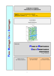
A. Vehicle type identification code and chassis
number
B. V.I.N. Plate (EEC regulations)
C. Engine type and number.
A.
B.
C.
D.
E.
I
F.
kg
o
12-
F
]
kg
G
]
kg
[
kg
M0TORE- ENGINE
N
VERSIONE-VERSION
2
N PER RICAMBI
8
N FOR SPARES
2
M
G.
o
H.
I.
L.
M.
N.
Manufacturer's name
Homologation number
Vehicle type identification code
Chassis manufacture number
Maximum authorised vehicle weight when
fully laden
Maximum authorised weight of fully laden
vehicle plus trailer
Maximum authorised weight on first axle
(front)
Maximum authorised weight on second axle
(rear)
Engine type
Body version code
Spares number
Correct value of smoke absorption coefficient
(for Diesel engines only)
Print n°
506.763/23
Introduction
Marea- Marea Weekend
2000 range @
Weights
OO.o
ENGINE T Y P E
16v
20v
Marea
1140
1165 (•)
1255
Marea Weekend
1200
1225 (•)
1315
1730
1755 (T)
1830
1795
1820 (T)
1895
1000
1000
1000
1000
Maximum permitted load on roof
80
80
Load on tow hook ball
(trailer with braking system)
70
70
400
400
1200
1300
(1400)«
Marea
+590=
(575)'
¥¥¥¥¥
Marea Weekend
+595=
(580)*
mrirnT
Permissible loads on the axles
Without braking
system
With braking
system
I
(*)
(•)
(T)
Loads that should never be exceeded
Specific figures for 1998 20v version
Specific figures for the Marea Weekend
Specific figures for the 1596 16v automatic transmission version
NOTE FOR VERSIONS WITH A C C E S S O R I E S : In the presence of special equipment (non standard air conditioning, sun
roof, trailer towing device, etc.), the empty weight increases and therefore the carrying capacity may decrease in relation to
the maximum permissible loads.
Copyright by Fiat Auto
3
Marea-Marea Weekend
Introduction
2000 range ©
Performance - Fuel consumption
OO.o
ENGINE T Y P E
16v
16v
C.A
20v
46
59
80
94
JTD
Speed km/h (half laden)
124
173
MAX
187
(185)*
139
182
187
(185)'
208
(206)*
46
54
(*) For Marea Weekend
Max. climable gradient
fully laden
Urban
Out-of-town
Fuel consumption in accordance with directive
1999/100/CE (litres/100 km)
CO2 exhaust emissions (g/km)
Combined
Marea
36
32
39
Marea Weekend
33
30
36
Marea
11.2
12.2
13.7
Marea Weekend
11.3
12.4
13.8
Marea
6.3
6.7
7.6
Marea Weekend
6.5
6.7
7.7
Marea
8.1
8.7
9.8
Marea Weekend
8.2
8.8
9.9
Marea
192
207
234
Marea Weekend
195
210
237
The fuel consumption figures in accordance with directive 1999/100/CE have been defined during the course of homologation
tests which include:
- An urban cycle which includes a cold start followed by a simulated varied urban cycle.
- A non-urban cycle which includes frequent acceleration in all gears simulating normal out-of-town use of the vehicle.
The speed varies between 0 and 120 km/h.
- The average combined consumption includes 37% urban cycle and 63% non-urban cycle.
The type of route, traffic conditions, driving style, weather conditions, trim level/equipment/accessories, presence of special
equipment and the state of the vehicle in general can lead to different fuel consumption figures from those established
using the above mentioned procedures.
The CO2 exhaust emissions (in g/km) are measured during the average combined cycle.
4
Print n°
506.763/23
Marea
Introduction
2000 range @
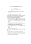
Dimensions
OO.o
F
Luggage compartment capacity ( V D A regulations): 4 3 0 d m
The height refers to an unladen vehicle
Engine types
3
A
B
c
D
E
F
G
H
5 / Jx14-43
6Jx15-43
884
2540
969
4393
1470
1470
1440
1440
1741
1425
5!4Jx14-43
6Jx15-43
884
2540
969
4393
1470
1470
1440
1440
1741
1425
6Jx15-49
884
2540
969
4393
1475
1430
1741
1428
884
2540
969
4393
1470
1470
1440
1440
1741
1425
Wheel rim
1
2
1
5 / Jx14-43
6Jx15-43
2
Copyright by Fiat Auto
5
Introduction
Marea Weekend
2000 range @ )
Dimensions
OO.o
3
3
Luggage compartment capacity with vehicle unladen (V.D.A. standards): 500 d m (1540 dm with seats folded)
Engine types
Wheel rim
A
B
C
D
E
F
G
H
5Y Jx14-43
6Jx15-43
884
2540
1066
4490
1470
1470
1440
1440
1741
1510
5%Jx14-43
6Jx15-43
884
2540
1066
4490
1470
1470
1440
1440
1741
1510
6Jx15-49
884
2540
1066
4490
1475
1435
1741
1510
884
2540
1066
4490
1470
1470
1440
1440
1741
1510
2
ifipl 20v
1
5 / Jx14-43
6Jx15-43
2
6
Print rf
506.763/23
Marea- Marea Weekend
Introduction
2000 range (§)
Capacities
OO.o
Product
Parts to be filled
Petrol > O.R. 95
Unleaded
i •' •• i r - F I ^ft
dm
(I)
3
Kg
•
diesel
50%
n
p
•
TP
16v
20v
JTD
63
63
-
-
-
63
7
7.6
6
(6.7 • )
(7.4 • )
(5.6 • )
4.5
5.5
4.8
4
4.7
4.25
3.8
(3.5*)
5
(4.5*)
4.3
(4*)
3.4
(3.1*)
4.45
(4*)
3.75
(3.55*)
1.98
1.98
1.65
1.8
1.8
1.5
4.3
-
-
3.9
-
-
Total capacity of cooling
system
•
Petrol engines
SELENIA 20K
(SAE 10W/40) ( • )
m-m
•
Total capacity
g|l
(•)
(•)
(*)
(•)
(••)
Diesel Engines:
SELENIA TURBO
DIESEL
(SAE 10W/40) ( • • )
TUTELACAR
ZC 75 Synth
frQQ
TUTELA
GI/2
*
-J»
•
•
Partial capacity
(scheduled changes)
•
•
•
•
Distilled water
For versions with air conditioning
Engine sump only
For temperatures below -20°C the use of S E L E N I A P E R F O R M E R S A E 5W-30 is recommended
For temperatures below -15°C the use of S E L E N I A WR D I E S E L 5W-40 is recommended
Copyright by Fiat Auto
7
Introduction
Marea-Marea Weekend
2000 range
Capacities
©
00.0
Product
Quantity
dm (I)
Kg
Parts to be filled
3
HI
TUTELA
Gl/A
-
0.8
•
TUTELA
MRM2
-
0.003
without
ABS
0.40
-
with
ABS
0.45
-
5
-
6.8
-
•
TUTELA
top4
r H
Total capacity
30%
*
8
+
d
- 10°C
50%
- 20°C
100%
I
J
+
s?>
Print n°
506.763/23
Marea-Marea Weekend
2000 range (§)
Introduction
Product characteristics FL Group
OO.o
Name of
product
Description
International designation
Application
SELENIA 20K
Synthetic SAE 10W40 multigrade engine oil.
Exceeds specifications ACEA A3-96/CCMC G5 and API
SJ
SELENIA
PERFORMER
Synthetic SAE 5W-30 multigrade engine oil. Exceeds
specifications ACEA A1 and API SJ
SELENIA
Turbo Diesel
Synthetic SAE 10W40 multigrade engine oil
Exceeds specifications ACEA B3 and API CD
SELENIA
WR DIESEL
Synthetic SAE 5W-40 multigrade engine oil. Exceeds
specifications ACEA B3 and API CF
Temperatures below
- 15°C
TUTELA CAR
ZC 75 SYNTH
SAE 75W-80 EP oil. Satisfies standards MIL-L-2105 D
LEV and API GL 5
Manual gearboxes and
differentials
TUTELA Gl/A
«ATF DEXR0N II D LEV» SAE 10W type oil for hydraulic Hydraulic power
power assisted steering
sisted steering
TUTELA GI/2
« ATF DEXRON II D LEV» SAE 10W type oil for automatic transmissions
Automatic
gearboxes
TUTELA MRM2
Water repellant, lithium soap based grease containing
molybdenum disulphide, consistency NLGI = 2
Constant velocity joints
TUTELA TOP 4
Synthetic fluid NHTSA n° 116 D0T4, ISO 4925, SAE
J-1703 and CUNA NC 956-01
DP1
Mixture of alcohol, water and surface active agents
CUNA NC 956-11
Paraflu
11
Diesel Mix
Copyright by Fiat Auto
Anti-freeze for cooling systems with mono-ethylene glycol base
CUNA NC 956-16
Additive for diesel fuel with protective action for Diesel engines
Temperatures below
- 20°C
as-
Hydraulic brakes and
hydraulically
operated
clutches
To be used undiluted
or diluted in windscreen
washer systems
Cooling circuits
Percentage to be used
50% up to -35°C
To be mixed with diesel fuel (25 cc per 10
litres)
9
Technical Data
Marea-Marea Weekend
2000 range @
Engine
OO.io
SPECIFICATIONS
OTTO 4 stroke
Cycle
^Q\^
1
Fuel system type
L—,1
M l
•
•
Integrated electronic injection - ignition
4
5
80.5
82
78.4
75.65
1596
1998
10.50 ± 0 . 1 5
10.5 ± 0 . 1 5
kW
(bhp)
76
(103)
110
(150)
rpm
5750
6500
daNm
(kgm)
14.5
(14.8)
18.1
(18.5)
rpm
4000
3750
Number of cylinders
•
Vt—•F-jZf
Is—A
Cylinder liner
\
mm
Stroke
mm
(bore)
W
j ^ J
TOHC
Timing gear
| q |
fifi-9
0
>
^ | * ^ ^
=
° -
a
c
e
"
c
m
3
Compression
ratio
9
ft
r
X
_
Maximum
power CEE
/
/
.. ... •
Maximum
torque CEE
,
... \
10
>
Print n°
506.763/23
Technical Data
Marea- Marea Weekend
2000 range
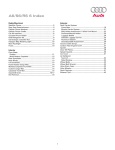
Engine: typical curves
©
OO.10
CV kW
CEE CEE
1000
ICEEEI\
2000
3000
4000
5000
6000
16v
7000
CV kW
CEE CEE
150
l| 20v
140
130H
120
110
100
90
80
N m kgm
CEE CEE
70
60
Typical engine curves obtained using the E C
method
50
40
30
20
1000
2000
Copyright by Fiat Auto
3000
4000
5000
6000
7000
The power curves illustrated are those obtained
using overhauled engines which have been run in,
without a fan and with an exhaust silencer and air
filter fitted, at sea level.
11
Technical Data
Marea-Marea Weekend
2000 range @
Engine: cylinder block/crankcase, crankshaft and associated
OO.io
DESCRIPTION
Values in mm
21.72-21.80
CCO*
Li
Main journals
0<
22.14-22.20
0
54.507-54.520
01
38.700-38.730
0 2
35.036-35.066
63.705-63.718
Auxiliary shaft bush housings
^
Cylinder liner
B
_oJI
80.500-80.510
82.000-82.010
80.510-80.520
82.010-82.020
80.520-80.530
82.020-82.030
9.7
12.5
80.452-80.462
81.952-81.962
80.459-80.471
81.959-81.971
80.468-80.478
81.968-81.978
0
X
0
0
Piston
0
12
0.4
Print n°
506.763/23
Marea- Marea Weekend
2000 range ( § )
Technical Data
Engine: cylinder block/crankcase, crankshaft and associated
OO.io
DESCRIPTION
2
^L__
^
°
„
Values in mm
Difference in weight
between pistons
Oi p
\
t
Lrfl-J
/
A
Piston
<
Cylinder liner/bon^
B
V
C
Gudgeon pin
housing
II^I^Hil^^HHiiililHH
20.997-21.001
20.002-20.007
20.990-20.995
19.996-20.000
is
4
S
]
1
0 BB^O
Gudgeon pin
4-3
0
[ O J mmm^0
^
^>
0.2
1
j ^ " Gudgeon pin - Housing
3
Piston ring grooves
^
1
1.225-1.245
1.220-1.240
F t
2
1.210-1.230
1.210-1.230
3
2.010-2.030
2.010-2.030
1
1.175-1.190
1.180-1.160
2
1.175-1.190
1.190-1.170
1.975-1.990
1.990-1.970
*
,
>
0
i
_
'—i T
«
Piston rings
-
Copyright by Fiat Auto
>
0.,4
13
Technical Data
Marea-Marea Weekend
Engine: cylinder block/crankcase, crankshaft and associated
2 0 0 0 range ( § )
OO.io
5-3
5-1
^
p
* *
Q P
" "
Piston rings
Piston ring
grooves
Piston ring
gap
in cylinder liner
01
t
14
0
2
0.035 0.070
0.040 0.080
0.020 0.055
0.020-0.050
0.020 0.055
0.020-0 060
0.150-0.350
0.200 0.350
0 200-0.400
0.250 0.500
0.200-0.450
0.250 0.500
Small end bush or
pin housing
01
23.939-23.972
22.939-22.972
Big end bearing
housing
09
48.630-48.642
51.354-51.366
Print n°
506.763/23
Marea- Marea Weekend
2 0 0 0 range
©
Technical Data
Engine: cylinder block/crankcase, crankshaft and associated
OO.io
mi
16v
M E A S U R E M E N T S AND FITTINGS
20v
Values in mm
01
0
2
24.016-24.041
23.007-23.027
21.004-21.009
20.006-20.012
Small end bush
4-7
Gudgeon pin
Small end bush
0.009-0.019
0.006 0 020
7-6
Small end bush
Bush housing
0.044-0.102
0.035-0.088
50.794-50.800
59.994-60.000
50.787-50.793
59.988-59.990
50.780-50.786
59.982-59.980
A
45.518-45.523
48.238-48.240
B
45.510-45.517
48.232-48.230
45.503-45.509
48.226-48.230
Crank
journals
01
8
Crank
pins
0
2
26.975 - 27.025
26.575-26.625
Li
Crankshaft bearings
L <
1.840-1.844
1.836-1.840
1.844-1.848
1.839-1.843
1.850-1.854
1.842-1.846
0.127
0
9-8
OP
Copyright by Fiat Auto
Main bearings
Journals
0 019-0 04b
XI-00
Supetsedes previous version
0 025-0.052
15
Technical Data
Marea- Marea Weekend
Engine: cylinder block/crankcase, crankshaft and associated
2 0 0 0 range
@
OO.io
M E A S U R E M E N T S AND FITTINGS
Values in mm
Big end
pins
10 K
* P [O
0
1.536-1.540
1.540-1.544
1.539-1.543
1.544-1.548
1.542-1.546
—BP
0.127
Crankshaft bearings - Main journals
10-8
1.537-1.541
Thust
washers
0.025-0.050
0.030-0.056
2.310-2.360
2.342-2.358
0.127
11-8
16
1£
Crankshaft endfloat
XII-9S
0 055-0 265
Supersedes previous v i s i o n
0 059 0 1 6 1
Publication
no.
506.763/24
Technical Data
Marea- Marea Weekend
2 0 0 0 range
Engine: auxiliary shaft
©
OO.io
16v
DESCRIPTION
Values in mm
NO Q
0,
35.664-35.684
0
1
•0D=Ljtr
23
Bushes for
auxiliary drive shaft
|0
2
01
eu
my
24
1
24-23
Copyright by Fiat Auto
35.593-35.618
i
Auxiliary drive shaft
bearings
1 0\
O
-4-K-
32.000-32.020
02
Shaft
02
DUSnes
should always be interfetrnce
Crankcase seats
Shaft bearings
Bushes
31.940-31.960
0i
0.046-0.091
0
0 040-0.080
17
Technical Data
Marea-Marea Weekend
Engine: cylinder head and valve gear components
2 0 0 0 range ( § )
OO.io
DESCRIPTION
Values in mm
Camshaft supports
in cylinder head
n
0
26.045-26.070
i_n
19.100-19.150
Valve guide bore
In cylinder head
12
Valve
seat
12.950-12.977
0
HQ
45°±5'
S3
45°±5'
a
approximately 2
Volume of
combustion chamber
in cylinder head
( ) Cap measurement
18
cm"
33.3 (•)
38.2
( • ) Indicative value
Print n°
506.763/23
Marea- Marea Weekend
Technical Data
Engine: cylinder head and valve gear components
2000 range (Q)
OO.10
lev
20v
DESCRIPTION
Values in mm
<—u——u—Tappet
housing in cylinder
33.000 - 33.025
0
h e a d
01
HQ
Valve guide
13
7.022-7.040
r ^ H
13.010-13.030
0 2
ffl
-0
2
0.05-0.10-0.25
02
Valve guide
Bore in cylinder head
13-12
HQ
0.033 0.080
01
6.982-7.000
6.975-6.990
0 2
30.200-30.500
29.900-30.200
45° 3 0 ' ± 5 '
a
Valve
0 i
6.974-6.992
6.960-6.975
02
29.750-30.050
25.900-26.200
a
HQ
Valve
Valve guide
14-1
HQ
®
45° 3 0 ' ± 5 '
0.022-0 058
0.032 0.065
0.030 0.066
0.047 0.080
11.08-12.07daN
29.5
Hi
15
Hi
Inner valve spring
I H 2
21.58-23.54 daN
H
Hi
16
Hi
Outer valve spring
Copyright by Fiat Auto
20
2
25.00-28.00 daN
27.07-29.43 daN
34.6
34
59.2-65.0 daN
48.46-52.38 daN
26
24.5
19
Technical Data
Marea-Marea Weekend
Engine: cylinder head and valve gear components
2 0 0 0 range
@
OO.io
DESCRIPTION
Values in mm
Camshaft bearings
01
29.944-29.960
02
52.400-52.415
03
52.800-52.815
04
53.200-53.215
0B
53.600-53.615
»16v
01
i
17a
02
03
04
05
r
¥ - T_j-§^T_rtj-^p^
f^Pl 20 v
26.000-26.015
0
17c
,0,0
i0
i 0
i0. i 0
19.250-19.330
17,
gt
Cam lift
HQ
8.5
®
1• 2 b - c
17b-C
20
|-^ A--,
jj) [j
Camshaft
bearings
Deanngs
Cylinder head
supports
radial
0.030-0.070
axial
0.100-0.230
P/wr
/?°
506.763/23
Marea- Marea Weekend
Technical Data
Engine: cylinder head and valve gear components
2000 range (Q)
OO.io
16v
20v
DESCRIPTION
Values in mm
r-jn_ _jnjT_^jn -^JTjnr^-JTJ |
L-f -n_rij^-T_n_rLj - ijtj ^^
-
J
J
,
-,
j
0i
29.989-30.014
02
52.445-52.470
03
52.845-52.870
04
53.245-53.270
05
53.645-53.670
_
Camhaft supports in camhaft housing
n—,—nnTL
• Q M
17-18
^
P
»| |<
Tappet housings
33.000-33.025
0
Camshaft bearings
Camshaft housing supports
0.030-0.070
—-^_J~l—
r-u—u~~l_
—LJ—^—LJ i-a_r>—
-
19
O H O
1-1
Tappet
0
19-12
^
P
H H
Tappet
head
Bore in cylinder
cyli
19-18
'"
^
P
»| |<
Tappet - Housing in
camshaft housing
, 5
1 0
17-20
1
Copyright by Fiat Auto
Clearance for
timing check
32.959-32.975
0.025-0,066
0.02S-0.066
HQ
®
0.45
0.45
HQ
Operational
clearance
®
Hydraulic tappets
21
Technical Data
Marea- Marea Weekend
Engine: cylinder head and valve gear components
2000 range @)
OO.io
TIMING D I A G R A M S
A
opens before
T.D.C.
0°
9° (*)
after T.D.C.
B
closes after
B.D.C.
34°
49°(*)
C
opens before
B.D.C.
24°
40°
closes after
T.D.C.
0°
0°
imaKe
CXnaUSl
D
(*) With phase transformer on:
22
HQ
®
A - opens before T.D.C: = 9°
B - closes after B.D.C: = 31°
Print n°
506.763/23
Technical Data
Marea- Marea Weekend
Engine: counter balance shaft
2000 range @ )
OO.io
20v
Values in mm
DESCRIPTION
25
Counter-balance shaft operation
through oil pump driven gear
01
19.900 - 20.000
02
46.989 - 47.000
0
19.980 - 19.993
0
46.975 - 47.000
27
0
Ball bearings for counter-balance shaft
25 t r
c)
=tt=
i
Counter-balance shaft bearings
«
9
Bearing seats in cylinder
block/crankcase
_
Oi p
-4+-
25-27
Copyright by Fiat Auto
CV.,
V-J
Ball beari ngs
Crankcasf
Crankcase seats
+0.011 - -0.025
Shaft bearings
Ball bearings
• 0.020
-0.003
23
Technical Data
Marea- Marea Weekend
Engine: lubrication
2000 range
©
OO.io
LUBRICATION - DESCRIPTION
Values in mm
forced circulation, via geared pump
with cartridge oil filter in series
Engine lubrication circuit
Oil pump: type
gears
Pump operated
through auxiliary shaft
Oil pressure relief valve
incorporated in the oil pump
Full flow filter
cartridge
Low oil pressure transmitter
electrical
IlimBi
between the edge of the gears
and the pump casing
^ ^ ^ • • • F
JjOj^^^U
^^*^^B§
between the upper edge of the
gears and the pump cover
Clearance between the bearing and the driven gear
Clearance between the drive gear shaft and the
housing in the pump casing
Oi p
* *
between drive gear
and driven gear
0
© J±
when idling > 1 bar
at 4000 rpm > 4.5 bar
Operating pressure at a temperature of 100°C
Pi
9.0-9.8 daN
31
9
1
Hi
I
H?
P2
H
24
2
6.92-7.21 daN
21
Print n°
506.763/23
Technical Data
Marea-Marea Weekend
2 0 0 0 range
Engine: lubrication
©
OO.io
Values in mm
LUBRICATION - DESCRIPTION
forced circulation, via geared pump
with cartridge oil filter in series
geared located in the
crankshaft front cover
Engine lubrication circuit
Oil pump: type
by chain driven by crankshaft
Pump operated
incorported in crankshaft front cover
Oil pressure relief valve
Full flow filter
cartridge
Low oil pressure transmitter
electrical
l l O m H
^ ^ ^ • • • F
(EQi^^^U
^^^^BBf
Oi 0
-*r-H-
between the edge of the gears
and the pump casing
between upper edge of
gears and pump cover
between drive gear
and driven gear
©
©
J :
when idling 1 bar
at 4000 rpm > 4 bar
Operating pressure at a temperature of 100°C
11.73-12.51
2
J*
35
Hi
Oil pressure relief valve spring
Copyright by Fiat Auto
25
Technical Data
Marea-Marea Weekend
Engine: cooling system • fuel system
2 0 0 0 range ( § )
OO.io
COOLING
coolant circulation via centrifugal pump, radiator
and two speed fan operated by engine control unit
Cooling circuit
Water pump operated
fl
via belt
( ^ + \
^
\f
Engagement
of fan
Operated by
control unit
•
S T A
9
E
vj^/
s t a g e
v
?
Z
.
9
(s\oo\
v
v
90°H-94°C
1
y
—'
stage 2
95°+99°C
(•)
rn
a x
90°+94°C
93°-H94T
(•)
98+99T
8 1 ° - 85°C
D
101 C+105'C
99+103°C
opening
9 . 5 mm
valve travel
Fitting clearance between impeller
vanes and pump casing
101+102°C
85V89X
opening starts
Engine coolant
thermostat
96°+97T
p
j |<
0.3:1.1 mm
0.4 : 0 . 9 5 mm
Pressure for checking system water tightness
0 . 9 8 bar
Pressure for checking exhaust valve on expansion
tank cap
0 . 9 8 bar
( • ) Versions with climate control
FUEL F E E D S Y S T E M
Make
Electronic integrated
injection-ignition
MPI - I.A.W.
Weber-Marelli
Electronic integrated
injection-ignition
MPI - BOSCH Motronic
Pump
electric immersed in the tank
Output
> 1 2 0 l/h
Fuel pressure regulator setting
26
3 bar
Print n°
506.763/23
Marea-Marea Weekend
2 0 0 0 range (j§)
Technical Data
Engine: fuel system - special tools
OO.io
I N T E G R A T E D E L E C T R O N I C INJECTION/IGNITION S Y S T E M
COMPONENTS
Manual gearbox
I.A.W. 4EF. B3
Automatic transmission
I.A.W. 4EF. L1
Electronic control unit
Air pressure sensor
M. Marelli TPRT 05
M. Marelli EC2
Fuel vapour solenoid valve
Throttle case
M. Marelli 46 SX F2
M. Marelli IB 02
Idle adjustment actuator
Injector
M. Marelli IWP 109
Fuel pressure regulator
MARWALL RPM 84
Coolant temperature sender unit
SYLEA 402.386.01
Top Dead Centre and rpm sensor
M. Marelli CVM 02
Throttle position sensor (potentiometer)
M. Marelli IPF 2C
NGK KNE 11
Detonation sensor
Electric fuel pump (*)
MARWALL ESS 291
Lambda sensor upstream of catalyzer
NTK OZA 534 A1
Lambda sensor downstream of catalyzer
NTK OZA 532 A1
Fuel filter
MARWALL FA 5325 IN
SYLEA SFA 200
Timing sensor
Ignition coil
Champion BAE 920A/
BERU 0.040.100.029
SPECIAL TOOLS
(*) Use tool 1870736000 for removing-refitting the fuel pump retaining ring nut
Copyright by Fiat Auto
27
Technical Data
Marea- Marea Weekend
Engine: fuel system - special tools
2 0 0 0 arnge © )
OO.io
INTEGRATED ELECTRONIC INJECTION/IGNITION SYSTEM COMPONENTS
Injection/ignition system electronic control unit
Bosch ME31F001
Motorized throttle body
Bosch 0.250.003.052
Injector
Bosch 0.280.155.770
Electric fuel pump (*)
Bosch 0.580.313.011
Air flow meter
Bosch 0.281.002.199
Engine coolant temperature sensor
Lambda sensor (one upstream and one downstream of the catalyzer)
ELTH 2690350 - SYLEA
402.183.01
Bosch LS F4
0.258.006.193
Fuel vapour solenoid valve
Bosch 0.280.142.340
Detonation sensor
Bosch 0.261.231.131
Hall effect injection timing sensor
Bosch 0.232.101.036
Top Dead Centre and rpm sensor
Bosch 0.261.210.160
Ignition coil
Bosch 0.221.504.014
SPECIAL TOOLS
(*) Use tool 1870736000 for removing-refitting the fuel pump retaining ring nut
28
Print n°
506.763/23
Technical Data
Marea-Marea Weekend
2 0 0 0 range
Engine
©
OO.io
JTD
SPECIFICATIONS
Diesel 4 stroke
Cycle
Timing gear
single overhead camshaft
Direct injection
Turbocharger + intercooler
Fuel system type
4 in line
Number of cylinders
r
0
Cylinder liner
(bore)
mm
82
Stroke
mm
90.4
Displacement
cm
1910
Compression
ratio
18.45 ± 0.5
kW
(bhp)
81
(110)
rpm
4000
daNm
(kgm)
20
(20.4)
rpm
1500
Max power CEE
Max torque CEE
Copyright by Fiat Auto
29
Technical Data
Marea- Marea Weekend
Engine: cylinder head and valve gear components
2 0 0 0 range ( § )
OO.io
CYLINDER HEAD G A S K E T ENGINE | | £ k JTD
Average - maximum piston
projection (mm)
Head gasket size (mm)
Head gasket no. of refs.
0.014 0.104
0.770-0.870
0
0.105-0.205
0.870-0.970
1
0.206-0.294
0.970-1.070
2
TIMING D I A G R A M S
ft
JTD
TIMING A N G L E S
opens before
TDC
0°
ends after BDC
32°
opens before
BDC
40°
ends after TDC
-2°
Intake
B
Exhaust
30
®
Print n°
506.763/23
Marea- Marea Weekend
2000 range (§)
Technical Data
Engine: supercharging
OO.io
S U P E R C H A R G I N G Turbocharger operated by exhaust gases with waste-gate pressure valve and air/air
heat exchanger (intercooler)
COOLING
Turbocharger: type
Garret GT 17 variable geometry
Maximum supercharging pressure
1 bar
6
5
1.
2.
3.
4.
5.
6.
7.
8.
Compressor inlet
Oil inlet
Turbine outlet
Oil outlet
Turbine inlet
Oil inlet
Oil outlet
Compressor outlet
Copyright by Fiat Auto
31
Technical Data
Marea- Marea Weekend
Clutch
2 0 0 0 range
©
00.18
Values in mm
@
Make
V
dry, single plate with bearing
contact
Operating mechanism
Spring
Spring loading
daN
400
600
485
200
230
215
137
155
147
«
01
02
Pressure plate
/
tC/
^t/ f
r
I
Distance between pedal in end of
travel position and pedal in rest position
Clutch operation
^EflHi^SBMj^
[f^^^^UHL
32
0
0
Clutch operating pump
Operating cylinder
Q
Q
163
144.5
mechanical
Hydraulic
-
16.05
(3/4»)
-
25.4
(1»)
Print n°
506.763/23
Technical Data
Marea- Marea Weekend
Gearbox and differential
2000 range (§)
00.21-27
20v
Make
IgB)
JTD
C.510.5.21
C.513.5.13
GEARBOX
snap
_T|4fl_
(Porsche type)
o
u
Synchronizers
„
V
b a U l k
-
^$13?
I
1
r j n g
oo
spur
^
V teeth
H|
r
I
G e a r s
straight
teeth
$ oo
(| S
I'S
W>
HI
3.909
3.545
3.909
2.238
2.238
2.238
1.444
1.520
1.444
1.029
1.156
1.029
0.872
0.919
0.767
3.909
3.909
3.909
Gear ratios
S i
Copyright by Fiat Auto
33
Technical Data
Marea-Marea Weekend
Gearbox and differential
2000 range
©
00.21-27
m
DIFFERENTIAL
Ratio crown
wheel and pinion
reduction
-J-
Ratio at the wheels
20v
20v
JTD
3.823
(17/65)
3.733
(15/56)
3.150
(20/63)
14.944
13.233
12.313
8.556
8.354
7.050
5.520
5.674
4.549
3.934
4.315
3.241
3.334
3.431
2.416
14.944
14.592
12.313
conical roller bearings
Differential internal housing bearing
with snap rings
Adjustment of bearing pre-loading
mm
0.05
1.70 -2.60
Spare snap ring thickness
T
Recommended
interference for
exact bearing
pre-loading
mm
bonrings not loaded
0.12
beatings loaded (350 daN)
0.08
0.10
mm
Clearance between planet/satellite gears
3
c
0
Adjustment of clearance between planet/satellite gears
mm
no adjustment
by
shims
0.80 - 1.25
Spare snap ring thickness
34
Print n°
506.763/23
Technical Data
Marea- Marea Weekend
Automatic transmission - differential
2000 range (§)
00.21-27
GEARBOX
A U T O M A T I C AISIIM
ENGINE T Y P E
Speeds
. 1 .
.1,
Gear ratios
o o o o o
2.807
OOOOO
1.479
o o o o o
1.000
OOOOO
0.735
o o o o ©
2.769
1.019 (54/53)
Idler ratio
Torque converter
T
ooooq
X
0 mm
Drive torque ratio
Quantity of
oil
Total, with gearbox converter, radiator and pipes
empty
Replacement only
216
2.150
6 litres (5.4 kg)
4.3 litres (3.9 kg)
GI/2
DIFFERENTIAL
Ratio crown wheel
and pinion
reduction
Final drive ratio
Ratio at the wheels
Copyright by Fiat Auto
OOOOO
OOOOO
OOOOO
OOOOO
OOOO©
3.505 (82/23)
3.633 (54/53x82/23)
10.198
5.373
3.633
2.670
10.060
35
Technical Data
Marea
Braking system
2000 range ©
00.33
FRONT B R A K E S
Values in mm
0
257
11.80-12.10
19.80-20.10
11.10
18.55
10.20
18.20
Disc
permitted
1
Brake
pads
0
Shoe
jgg^^^^L^^
* ^ i ? f
Master cylinder
(pur
jmp)
permitted
1.5
0
54
0
22.225 (7/8")
Brake servo
Iso-Vac 8"
pneumatic vacuum
acting on all four wheels
Distance of hydraulic
piston control rod
\
\
from master cylinder
—>4k- support plate
22,45 - 22,65
f j..J
(*) For version with automatic transmission
REAR B R A K E S
203.10 - 203.40
Drum
1
204.10
0
\
l°\
/°]
v w y
Shoes
^ ^ ^ J ^
Cylinders
^ >
S
< ^
Reduction
'°
r a t
permitted
204.70
.„ .
permitted
1.5
22.00
0
(
Pressure
1
regulators (•)
j Load proportioing
I
valves (•)
0.36
-
-
0.36
( • ) Not fitted on versions with A B S
36
Print n°
506.763/23
Technical Data
Marea Weekend
2000 range
Braking system
©)
00.33
Values in mm
FRONT B R A K E S
0
-«H«-s
257
19.80-20.10
0
Disc
18.55
permitted
1
Brake
pads
0
allowed
1.5
Caliper
0
54
Master cylinder
(pump)
0
22.225 (7/8")
Iso-Vac 8"
pneumatic vacuum
acting on all four wheels
Brake servo
L
18.20
Distance of hydraulic piston push rod from master
cylinder support plate
22.45 - 22.65
REAR B R A K E S
228.30-228.60
0
229.30
|
v
Vol J o j Shoes
^ >
S <C^
permitted
230.00
permitted
1.5
0
Load proportioning valve
(•)
Ratio
(reduction)
22.00
acting on rear wheels
0.36
( • ) Not fitted on versions with A B S
Copyright by Fiat Auto
37
Technical Data
Marea- Marea Weekend
Braking system
2000 range
@>
00.33
M16v
Values in mm
FRONT B R A K E S
0
283.800 - 284.200
21.800 - 22.100
Disc
20.55
permitted
1
Brake
pads
20.20
allowed
1.5
0
54
0
23.81 (15/16")
£ Caliper
Master cylinder
(pump)
Iso-Vac 8" + 7"
pneumatic vacuum
acting on all four wheels
Brake servo
Distance of hydraulic piston push rod from master
L cylinder support plate
22.45 - 22.65
REAR B R A K E S
0
240
10.80 + 11.10
0
II II
Disc
10.10
allowed
9.20
Brake
P
allowed
1.5
Shoe
0
34
a d s
"^s
0
Load proportioning valve
(•)
Ratio (reduction)
acting on rear wheels
0.36
( • ) Not fitted on versions with A B S
38
Print n°
506.763/23
Marea-Marea Weekend
2000 range
Technical Data
Steering
(§)
00.41
n^p| 16v
ENGINE T Y P E
IESi JTD
Make
Rack and pinion power assisted
'
:
o
©
3
2.9
142±1.5 mm
137±1.5 mm
10.7
11
steering wheel
-<
%
Wh eel
rack and pinion
travel
\
/
\
/
1.
^
Minimum turning circle
m
* r
# |
Steering angle
outer
wheel
^
inner
wheel
^
31° ± 30'
38° ± 30'
Steering column
with t w o universal joints
Copyright by Fiat Auto
39
Technical Data
Marea-Marea Weekend
Wheels
2000 range
(§)
00.44
1
ENGINE TYPE
Wheel rim
pressed
light
steel
alloy
1
5 / Jx14H-43
2
6Jx15" H2-43
Tyre
Tubeless
radial, type
185/65 R14 86H
195/55 R15 84V(**)
185/65 R14 86Q(»)
195/55 R15 88Q (•)
H
II
Tyre
BHH
II
pressure
Front
heavy
average
load
load
Rear
heavy
average
load
load
2.1
2.2
2.3
2.5
bar
bar
bar
bar
2.1
2.2
2.3
2.5
bar
bar
bar
bar
2.1
2.2
2.3
2.5
bar
bar
bar
bar
(**)
-
1
5 / Jx14H-43
2
6Jx15" H2-49
6Jx15" H2-43
195/60 R15 88V
195/60 R15 88Q(«)
185/65 R14 86H
195/55 R15 84V(**)
185/65 R14 86Q(«)
195/55 R15 88Q(«)
(**)
SPARE
WHEEL O
5y x14"-43 (A)
4.00Bx15»M-35
2
-
185/65 R14 86H (A)
125/80 R15 95M
4.2
bar
With the tyres warm, the inflation pressure should be increased by +0.3 bar in relation to the recommended figure.
With winter tyres the inflation pressure shold be + 0.2 higher than the recommended figure for the standard
tyres.
(*)
(**)
(•)
(A)
40
Speed limit: 80 km/h
Optional
Winter tyres
For the TAXI version
Print n°
506.763/23
Technical Data
Marea- Marea Weekend
2000 range
Wheels
©
00.44
unladen vehicle ( • )
WHEEL ALIGNMENT
camber (**)
36' 24» ± 30'
±3*
caster (**)
front
suspension
toe-in
0
1 57' ± 30'
-1 - 1 mm
offset
front wheels
camber (**)
-0° 45' ± 30'
U1
rear
suspension
toe-in (**)
2 ± 2 mm
thrust angle
rear wheels i
(**) Angles not adjustable
( • ) With the tyres inflated to the correct pressure and the vehicle in running order with 5 litres of fuel
( • ) Angular values, which cannot be adjusted, used for the correct alignment of the vehicle
Copyright by Fiat Auto
41
Technical Data
Marea- Marea Weekend
Front suspension
2000 range
@
00.44
Front suspension independent, Mac Pherson type with transverse lower track control arms secured to an
auxiliary crossmember. Offset coil springs and double acting, telescopic, hydraulic shock absorbers. Antiroll bar connected to the telescopic damper.
CLASSIFICATION O F S P R I N G S A C C O R D I N G TO V A R I O U S V E R S I O N S AND ENGINE T Y P E S
ENGINE TYPES
VERSIONS
Standard
E
C
Standard with ABS
E
C
With air conditioning
D
B
With air conditioning, ABS and all options
D
B
With air conditioning and ABS
D
B
Standard with automatic transmission
D
Standard with automatic transmission and ABS
D
With air conditioning and automatic transmission
C
With air conditioning, ABS and all options
C
B
With ABS (fitted as standard)
With ABS (fitted as standard) and air conditioning
With ABS (fitted as standard), air conditioning
and all options
A
A
SPECIFICATIONS O F V A R I O U S S P R I N G S
Coil springs
Wire diameter
A
mm
13.6±0.05
B
C
13.5±0.05
Number of effective coils
E
13.2±0.05
13.2±0.05
3.75
Clockwise
Coil direction
Released spring height
D
mm
Load under which spring height is
.
173 mm
The springs have been divided into two categories identifiable by a mark
yellow (*) for those with a height of >173 mm
under a load of:
green (*) for those with a height of <173 mm
under a load of:
a
m
449
448
434
425
413
432±17
417±17
397±16
353-383
336-364
432 daN
417 daN
397 daN
368 daN
350 daN
( ) Springs of the same type must be fitted
42
Print n°
506.763/23
Technical Data
Marea- Marea Weekend
2000 range
Front suspension
©
00.44
ENGINE T Y P E
h|p>
jrD
Dampers
Double acting, telescopic, hydraulic
Make
Open (start of buffering)
mm
508 ± 2.5
501 ± 2.5
Closed (iron against iron)
mm
361 ± 2.5
354 ± 2.5
Stroke
mm
147
mm
18
Anti-roll bar
Anti-roll bar diameter
Copyright by Fiat Auto
43
Technical Data
Marea
Rear suspension
2000 range
(§)
00.44
Rear suspension independent with track control arms anchored to an auxiliary crossmember. Variable
flexibility coil springs and anti-roll bar. Gas shock absorbers with low friction coefficient lower bushes.
l o p i lev
ENGINE T Y P E
ICphov
Coil springs
Wire diameter
mm
Number of effective coils
12.3 ± 0.1
5.93
Coil direction
clockwise
Released spring height
mm
Height of spring under a load of:
347-373 daN
m
m
316
184
Spring are divided into two categories,
identified by markings
> 184
yellow (1) for those:
under a load of
green (1) for those:
under a load of:
(1)
360 daN height of mm
360 daN height of mm
< 184
Springs of the same type must be fitted.
Dampers
Make
double acting, telesopic, gas
Open (start of damping action)
mm
321 ± 2
Closed (iron against iron)
mm
224 ± 2
Stroke
mm
97
mm
17
Anti-roll bar
Anti-roll bar diameter
44
Print n°
506.763/23
Marea Weekend
Technical Data
2000 range o
Rear suspension
00.44
Rear suspension independent with track control arms anchored to an auxiliary crossmember. Variable
flexibility coil springs and anti-roll bar. Gas shock absorbers with low friction coefficient lower bushes.
ENGINE T Y P E
Coil springs
Wire diameter
mm
Number of effective coils
12.3±0.1
12.8±0.1
5.93
5.93
Coil direction
clockwise
mm
320
322
419-445 daN mm
184
-
-
184
>184
_
-
>184
<184
-
-
<184
Released spring height
Spring height under
a load of:
432 daN mm
Spring are divided into two categories,
identified by markings
412 daN
o T
yellow (1) for those:
under a load of
m
m
hpinht
a
432 daN
of mm
a
412 daN
_
432 daN
(1)
J S *
o t
green (1) for those
under a load of:
a
m
m
h p i f l h t
e i
" f£J
ot mm
Springs of the same type must be fitted.
Dampers
double acting, telesopic, gas
Make
Open (start of damping action)
mm
321 ± 2
Closed (iron against iron)
mm
224 ± 2
Stroke
mm
97
mm
17
Anti-roll bar
Anti-roll bar diameter
Copyright by Fiat A uto
45
Technical Data
Marea- Marea Weekend
Electrical system
2 0 0 0 range ( § )
00.55
i^p}
S T A R T E R MOTOR
ALTERNATOR
16v
Bosch
DW -12V -1.1 kW
Valeo
DGRA-12V-1,3kW(B)
Bosch
KCB1-14V-45/80A
Bosch
KCB2-14V-50/90A
(•) n
VOLTAGE REGULATOR
J^M) 20v
Bosch
0 74.5-1.1/12V
M. Marelli
A127IR-14V-55/100A
Bosch
O 78.5-2 kW/12V
M. Marelli
A115IM-14V-55/105A
M. Marelli
A115IR-14V-70/120A
(•)
BUILT IN ELECTRONIC
12V-50Ah-250A
12V-60Ah-380A
(A)
n
12V-50Ah-250A
12V-60Ah-380A
12V-70Ah-450A ( A )
Integrated electronic
injection-ignition
MPI I.A.W.
Weber-Marelli
Injection-ignition
Bosch Motronic MPI
integrated electronic
-
IGNITION
COIL
M. Marelli BAE 920 A
Bosch 0.221.504.014
-
SPARK PLUGS
NGK BKR5EZ
Champion RC10YCC
Champion RC8BYC
-
-
-
Bosch EDC 15 C7
BATTERY
IGNITION S Y S T E M
C O N T R O L UNIT
INJECTION A D V A N C E E L E C TRONIC
( • ) For vehicles with climate control system
(*) North European version
( A ) For the TAXI version
( • ) Alternative
46
Print n°
506.763/23
Marea- Marea Weekend
2000 range
Technical Data
Electrical equipment: starting
(§)
00.55
l^p| 20v
S T A R T E R MOTOR
Bosch
DW -12V -1,1 kW
Make
Voltage
Bosch
0 74.5-1.1/12
V
Nominal power
kW
I^P)
JTD
Bosch
0 78.5-2 KW/12
12
1.1
1.1
Rotation, pinion side
2
clockwise
No. of poles
4
6
Winding
permanent magnets
windings in series
Engagement
6
free wheel
Operation
solenoid
End float of armature shaft
mm
0.1-0.5
0.1-0.5
0.1-0.5
-
360-380
1150
8.15
1.30
500
1950
7.30
1.30
680-700
4.9
3.11
1200
5.5
3.0
-
60-80
4.9
4040
70-80
11.5
5450-5750
-
0.33-0.37
0.4
-
1.13-1.27
1.7
Data for bench test
Operating test (*):
current
speed
voltage
torque developed
A
rpm
V
daNm
Engagement test (*):
current
voltage
torque developed
A
V
daNm
Idle test (*):
current
voltage
speed
A
V
rpm
Relay
[
pull in Q
Winding
resistance (*)
\
1 hold in Q
-
Lubrication
Internal splines and
shaft bushes
Enagement sleeve and intermediate
disc
VS
+
SAE 10W
TUTELA MR3
(*) Data obtained at an ambient temperature of 20°C.
NOTE
When overhauling it is not necessary to undercut the insulator between the commutator bars
Copyright by Fiat Auto
47
Technical Data
Marea-Marea Weekend
Electrical equipment: recharging
2000 range
@)
00.55
l ^ p ) lev
rgp> JTD
Bosch
KCB1-14V-45/80A
M. Marelli
A115IM-14V-55/105A
ALTERNATOR
M. Marelli
A127IR-14V-55/100A
Make
Bosch KCB2-14V50/90A (•) (*)
Nominal voltage
of system
y
Maximum current
M. Marelli
A127IR-14V-70/120A
(•)
14
14
14
A
80 (90) ( * ) ( • )
100
105 (120)(«)
Nominal current at 1800 rpm
rpm
45 (50) ( * ) ( • )
55
55 (70)(»)
Nominal current at 6000 rpm
A
80 (90) ( * ) ( • )
100
105 (120)(«)
2.66-2.94
(2.47-2.73) (*)(•)
2.66-2.94
-
Field winding resistance between
the two slip rings ( A )
Direction of rotation (seen from control
side)
Clockwise
Diode power rectifiers
preconstituted bridge
( A ) Data obtained at an ambient temperature of 20°C.
( • ) For vehicles with climate control system
C) For the TAXI version
Electronic, built-in
VOLTAGE REGULATOR
BR1
Make
Alternator speed
for test
r
p
m
RTM 151 B
RTM 151A
7000
Thermal stabilization corrector
^
-
Test current
A
-
Regulation voltage ( A )
y
14.3-14.6
( A ) Data obtained at an ambient temperature of 23°C.
48
Print n°
506.763/23
Marea- Marea Weekend
2000
range © )
Technical Data
Electrical equipment: recharging
00.55
Alternator wiring diagram
Bosch KCB1-14V-45/80A
Bosch KCB2-14V-50/90A
M. Marelli A127IR-14V-55/100A
M. Marelli A115IM-14V-55/105A
Typical voltage regulator curves
M. Marelli RTM 151 A
Copyright by Fiat Auto
M. Marelli RTM 151 B
49
Technical Data
Marea-Marea Weekend
Electrical equipment: electronic injection- ignition
2000 range
©)
00.55
INTEGRATED E L E C T R O N I C
INJECTION/IGNITION S Y S T E M
r^p)
Make
lev
I.A.W. M.P.I. WEBER - MARELLI
Firing order
1-3-4-2
INJECTION/IGNITION C O N T R O L UNIT
Make
type
and
versions with manual gearbox
I.A.W. 4EF. B3
versions with automatic transmission
I.A.W. 4EF. L1
IGNITION COIL WITH 4 HIGH T E N S I O N INTAKES
Make
Champion
Type
BAE 920 A
Ohmic resistance of primary winding at 20°C
Q
0.580
Ohmic resistance of secondary winding at 20°C
Q
9100
SPARK PLUGS
NGK BKR5EZ
CHAMPION RC10YCC
Make and type
Thread on engine
Spark gap
M14x1.25
mm
0.8
TOP DEAD C E N T R E AND R P M S E N S O R
Make
M. Marelli
Type
CVM 02
Sensor winding resistance at 20°C
Distance (gap) between sensor and
crankshaft pulley tooth
Q
575-750
0.5 + 1.5
A D V A N C E ON ENGINE
With engine idling 700±50/min
50
4°
Print n°
506.763/23
Marea- Marea Weekend
2000 range ©
Technical Data
Electrical equipment: electronic injection- ignition
00.55
I^P)
INTEGRATED E L E C T R O N I C
INJECTION/IGNITION S Y S T E M
Make
20v
Bosch ME31F001
Firing order
1-2-4-5-3
IGNITION COIL (1 PER S P A R K PLUG)
Make
Bosch
Type
0.221.504.014
Ohmic resistance of primary winding at 20°C
Q
0.,4
Ohmic resistance of secondary winding at 20°C
Q
8500
TOP DEAD C E N T R E AND R P M S E N S O R
Make and type
Sensor winding resistance at 20°C
Bosch 0.281.002.102
Q
Distance (gap) between sensor and
crankshaft pulley tooth
774 + 946
0.8
H-
1.5
DETONATION S E N S O R
Make
Bosch
Type
0.261.231.095
S P A R K PLUGS
Make and type
CHAMPION RC8BYC
Thread on engine
Spark gap
Copyright by Fiat Auto
M 1 4 x 1.25
mm
0.8
51
Marengo^™
2000
Introduction and technical data
Index
range
oo.
page
INTRODUCTION
- Identification data
- Dimensions
- Weights
- Performance
- Fuel consumption
1
1
2
2
2
TECHNICAL DATA
-
Front suspension
Rear suspension
3
3
NOTE
This section gives technical data for the Fiat Marengo 2000 range equipped with a 1910 JTD EC F3 engine. For further information, see the Fiat Marea - Fiat Marea Weekend manual publication no. 506.763
and subsequent updates
Copyright by Fiat Auto
Marengo f l ™
Introduction
Identification data
2 0 0 0 range
OO.o
GEARBOX
VERSION
ENGINE
CHASSIS
666
ICSS) JTD
ZFA 185.000
186A6000
o
185CXT1A 03
DIMENSIONS (mm)
Engine type
Icii3i JTD
Copyright by Fiat Auto
A
B
C
D
AND
F
G
H
4490
1741
1510
2540
1470
1440
884
1066
1
Introduction
Marengo ® ™
Weights - Performance - Fuel consumption
2 0 0 0 range
oo.
ENGINE T Y P E
WEIGHTS
(values expressed in k g )
IE®!
JTD
1275
1845
1060
Permissible loads on the axles •
1060
Performance - Fuel consumption
36
52
Speed km/h (average load)
^5^)
97
136
186
36
^^j^^^^B
PT^
Wy
Fuel consumption figures as per
E
C
5.0
directive 1999/100 (litres/100 km)
Wheels:
Tubeless tyres with radial tread, type 185/65R14-86H
Pressed steel wheel rim, type 5%J x 14" - 43
2
Publication
no.
506.763/24
Marengo 0 ™
Technical Data
Suspension and wheels
2 0 0 0 range
OO.o
Rear suspension independent with track control arms anchored to an auxiliary crossmember. Variable
rate coil springs and antiroll bar. Gas shock absorbers with low friction coefficient lower bushes.
ENGINE T Y P E
Coil springs
Diameter of wire
mm
13.9 ± 0.1
Number of coils
5.93
Direction of coil
clockwise
Height of spring released
Height under
a load of :
4
2
4
±
4
5
6
mm
d
a
N
m
m
323
207
The springs are divided into two categories,
identifiable by a mark:
X X ° l
i
-i
x
load of:
440 daN
having a heigh, of
mm
> 207
green (1) for
those under a
i
J
x.
load of:
440 daN
having a height of
mm
^ 207
a
a
(1) When fitting, match springs of the same type.
Shock absorbers
Make
double acting, telesopic, gas
Open (start of damping action)
mm
321 ± 2
Closed (metal against metal)
mm
224 ± 2
Travel
mm
97
mm
19
mm
18
Anti-roll bar
Anti-roll bar diameter
FRONT SUSPENSION
Anti-roll bar
Anti-roll bar diameter
Copyright by Fiat Auto
3
Marea Weekend 9 ™*»
Introduction - Technical Data
2000 range
Index
00.
page
INTRODUCTION
-
Identification data
Performance - Fuel consumption
Fuel consumption
1
1
2
TECHNICAL DATA
ENGINE
-
Copyright by Fiat Auto
Specifications
2
Marea Weekend 9
2000 range
@>
Introduction
mnoocv
Identification data - Performance - Fuel consumption
OO.o
iQpl JTD 100 CV
CHASSIS
ENGINE
VERSION
GEARBOX
ZFA 185.000
182B9.000
185BXU1A
9f ?
666
ENGINE T Y P E
sHU) JTD 100 CV
36
62
Speed km/h (medium load)
97
136
184
36
Maximum climable
gradient fully laden
Fuel consumption
according to directive
1999/100/CE (litres/100 km)
CO2 exhaust emissions (g/km)
Urban
7.2
Extra-urban
4.4
Combi
5.5
145
The fuel consumption figures in accordance with 1999/100 EC standards were determined during the course of homologation
tests which include:
- an urban cycle which includes a cold start followed by a simulated varied urban cycle.
- an extraurban cycle which includes frequent acceleration in all gears simulating normal out of town usage of the vehicle.
The speed varies between 0 and 120 km/h.
- the average combined consumption figure includes 37% of the urban cycle and 63% of the non-urban cycle.
The type of route, traffic conditions, driving style, weather conditions, trim level/equipment/accessories, presence of special
equipment and the state of the vehicle in general can lead to different fuel consumption figures from those established
using the above mentioned procedures.
The CO2 exhaust emissions (in g/km) are measured during the combined average cycle.
Copyright by Fiat Auto
1
Technical data
Marea Weekend {_
JTD 100 CV
Engine
2000 range
©
OO.io
ICETTiliJTD 100
cv
SPECIFICATIONS
Cycle
Diesel 4 stroke
Timing
single overhead camshaft
Direct injection
Turbocharger + intercooler
Type of fuel system
9.
No. of cylinders
&8
4 in line
Cylinder liner
(bore)
mm
82
Stroke
mm
90.4
Capacity
cm
1910
Compression
ratio
18.45 ± 0.5
kW
(bhp)
74
(100)
rpm
4000
daNm
(kgm)
20
(20.4)
rpm
1500
Max power CEE
Max torque CEE
2
Print n°
506.763/25
Marea- Marea Weekend • *»
2000 range
Engine
Fuel feed system
(§)
10.
Pages
FUEL FEED SYSTEM
-
Copyright by Fiat Auto
Engine management system
Diagram showing engine exhaust assembly
Fuel anti-evaporation system
Location of diagnostic socket
Location of injection/ignition system
components in the engine compartment
Front Lambda sensor
.
Rear Lambda sensor
Catalytic converter heat shield
Catalytic converter
Exhaust manifold
Electric fuel pump with level sender unit
1
1
~2
2
3
4
4
5
5
6
7
Marea- Marea Weekend • ^
2000 range
(Q)
Engine
Fuel feed system
10.
ENGINE M A N A G E M E N T S Y S T E M
The Marea-Marea Weekend 1596 16v has a 4 cylinder in line engine, with 16 valves, 1596 cc, twin overhead camshaft and a Marelli IAW 4EF integrated electronic injection/ignition system.
The fuel system differs from the one described for the 1581 16v "99 range" version through the addition
of several variants to make it compatible with the EEC Stage 3 EOBD regulations.
The main modifications to the system can be summarized as follows:
-
Engine management control unit with IAW 4EF
Catalytic converter near the exhaust manifold to take maximum advantage of the heat of the gases.
Two Lambda senors, one upstream (front) and one downstream (rear) which check the quality of the
exhaust gases and the operation of the catalyzer.
Adoption of a timing sensor on the inlet side timing pulley.
D I A G R A M S H O W I N G ENGINE E X H A U S T A S S E M B L Y
1.
2.
3.
4.
5.
Exhaust manifold
Catalytic converter
Front Lambda sensor
Rear Lambda sensor
Silencers
Copyright by Fiat Auto
1
Engine
Marea- Marea Weekend
Fuel feed system
2000 range
@
10.
FUEL A N T I - E V A P O R A T I O N S Y S T E M
The fuel anti-evaporation system has several improvements, compared with previous versions, aimed at
sealing the fuel vapours on the outside.
In particular, the following measures have been adopted:
- multi-purpose valve on the tank to prevent leaks.
- New anti-evaporation solenoid valve and the adoption of rapid attachment connectors for the antievaporation system pipes.
- Plug on the fuel filler with attachment cable.
For further information on the fuel system, refer to publication: 507137.
Key
1.
2.
3.
4.
Filler
Multi-purpose valve
Active charcoal filter
Anti-evaporation
solenoid
valve
5. Fuel vapour intake on inlet
manifold
6. Fuel tank
7. Engine management electronic control unit
LOCATION OF D I A G N O S T I C S O C K E T
The diagnostic socket for the analysis of the engine management system is located under the
junction unit in the dashboard. This socket also
makes the connection with the diagnostic equipment (Examiner or other instruments) for the
other electronic control units on the vehicle.
In effect, it is a "standardized" 16-way diagnostic
socket which can be connected to the diagnostic
equipment using the "MPX97" adaptor.
2
Print n°
506.763/23
Marea- Marea Weekend 9*
Engine
Fuel feed system
2 0 0 0 range (Q)
10.
LOCATION O F INJECTION/IGNITION S Y S T E M C O M P O N E N T S IN T H E ENGINE C O M P A R T MENT
1
2
3
4
Key
1.
2.
3.
4.
5.
6.
7.
8.
9.
10.
11.
12.
13.
14.
Active charcoal filter
Anti-evaporation solenoid valve
Intake air pressure and temperature sensor
Engine idle adjustment stepping motor on
throttle casing
Throttle valve position sensor on throttle casing
System relay feed
Protective fuse
Throttle case
Maxi-fuse protecting I.E. system (EFI)
Speedometer sensor
Engine management control unit
Coolant temperature sensor
Ignition coil
Injectors
Copyright by Fiat Auto
5
6
7
8
9
15. Rpm and TDC sensor
16. Timing sensor
17. Spark plugs
3
Engine
Marea- Marea Weekend •
Fuel feed system
2000 range
@
FRONT L A M B D A S E N S O R
Removing
-
Disconnect the negative battery terminal.
1. Disconect the electrical conection (1a), release the wiring from the retaining band
(2) and disconnect the Lambda sensor (3).
Refitting
-
Position the sensor and tighten it to torque
avoiding forcing the component which
would damage it irreparably.
Apply special grease (e.g. Bosch 5
964080112) to the threaded part of the
sensor.
REAR L A M B D A S E N S O R
Removing
-
Position the vehicle on a lift.
Disconnect the negative battery terminal.
2. Disconnect the electrical connection (1)
and release the wiring from the retaining
bands.
3. Raise the vehicle
Lambda sensor.
and
disconnect
the
Refitting
-
Position the sensor and tighten it to torque
avoiding force on the component which
would damage it irreparably.
Apply special grease (e.g. Bosch 5
964080112) to the threaded part of the
sensor.
- Connect the connector and renew the
Lambda senor cable fastenings.
4
Print n°
506.763/23
Marea-Marea Weekend
2000 range
Engine
Fuel feed system
©
10.
C A T A L Y T I C C O N V E R T E R HEAT S H I E L D
Removing-refitting
- Position the vehicle on a lift and disconnect
the negative battery terminal.
1. Raise the vehicle and undo the bolts (1)
fixing the heat shield for the driveshaft
boot, then detach the heat shield (2); undo
the other lower bolt for the catalyzer heat
shield.
-
Lower the vehicle and detach the front
Lambda sensor as described in the relvant
paragraph.
2. Loosen the bands shown and detach the
air hose from the filter to the throttle casing, complete with resonator.
3. Undo the upper bolts fixing the heat shield
and detach it.
CATALYTIC CONVERTER
Removing-refitting
-
Position the vehicle on a lift and disconnect
the negative battery terminal.
Disconnect the front Lambda senor as described in the relevant paragraph.
Detach the catalytic converter heat shield
as described in the relevant paragraph.
4. Undo the nuts fixing the catalytic converter
to the exhaust manifold.
Copyright by Fiat Auto
5
Engine
Marea- Marea Weekend ©
16v
Fuel feed system
2000 range
@
1. Loosen the band securing the catalyzer
acting on the bolt (1) and undo the bolts
(2) fixing the band to the bracket.
2.
Disconnect the connector for the rear
Lambda sensor and release the cable from
the retaining bands along the routing.
3. Raise the vehicle, undo the bolts fixing the
catalytic converter to the rear exhaust pipe
and detach the converter, complete with
rear Lambda sensor.
E X H A U S T MANIFOLD
Removing-Refitting
-
-
Position the vehicle on a lift, disconnect
the negative battery terminal and disconnect the following components, as described in the relevant paragraphs.
Front Lambda sensor
Catalytic converter heat shield
Catalytic converter.
4. Remove the protective cover for the power
assisted steering pump drive belt.
6
Print n°
506.763/23
Marea- Marea Weekend •16v
2000 range
Engine
Fuel feed system
©
10.
1. Loosen the belt tension using the lock nut
(2) and the adjustment screw (1); then release the belt from the pulley.
2. Undo the bolts fixing the bracket for the
power assisted steering pump mounting
and detach the pump.
3. Undo the nuts fixing the exhaust manifold
to the cylinder head and detach the manifold.
-
To refit, reverse the order of the operations
carried out for the removal; tension the
power assisted steering pump drive belt,
using the adjustment screw; use tool
189576200 to check that the tension is
between 32 and 45 daN.
E L E C T R I C F U E L P U M P WITH L E V E L
S E N D E R UNIT
Removing-refitting
-
Disconnect the negative battery terminal.
Lift up the lining in the luggage compartment and remove the fuel pup protective
cover.
- Disconnect the electrical connection for the
electric pump assembly and the fuel supply
and breather pipes.
4. Undo the ring nut fixing the electric fuel
pump to the tank using tool 1870736000.
The gasket on the tank housing should be
replaced each time the pump drip tray is
removed-refitted.
NOTE
Copyright by Fiat Auto
The position of the
and is established
the housing in the
correspond to the
pump drip tray.
fuel pump is fixed
by a reference in
tank which souId
projection on the
7
Marea- MareaWeekend • **
2000 range @
.
Engine
.
Index
10.
.
Page
FUEL FEED S Y S T E M
-
Copyright by Fiat Auto
Engine management system
Location of injection/ignition system
components
Location of diagnostic socket
Removing-refitting accelorometer
Removing-refitting front Lambda sensor
Removing-refitting rear Lambda sensor
Removing-refitting heat shield
Removing-refitting catalytic converter
1
2
2
3
3
4
5
7
Marea- Marea Weekend &
2000 range (§)
Engine
Fuel feed system
ENGINE MANAGEMENT S Y S T E M
Foreword
The Marea-Marea Weekend 1998 20v is equipped with a 5 cylinder in line engine with 20 valves, 1998
cc, twin overhead camshaft and a Bosch ME3.1 integrated electronic injection/ignition system.
The fuel system differs from the one described for the 1998 20v "99 range" version through the addition
of several variants to make it compatible with the EEC Stage 3 EOBD regulations.
The main modifications to the system can be summarized as follows:
- Catalytic converter near the exhaust manifold to take maximum advantage of the heat of the gases.
- Two Lambda sensors, one upstream (front) and one downstream (rear) which check the quality of the
exhaust gases and the operation of the catalyzer.
- Adoption of an accelerometre sensor on the right shock absorber turret, used to distinguish between
engine torque variations doe to the uneveness of the road surface and those due to failed ignition in
the combustion chamber (misfire).
- Adoption of a timing sensor on the inlet side timing pulley.
- Multi-purpose valve on the tank to prevent leaks.
- Adoption of raipd attachment connectors for the anti-evaporation system pipes.
- Cap on the fuel filler with an attachment cable.
For further information on the fuel system, refer to publication 507137.
D I A G R A M SHOWING ENGINE E X H A U S T A S S E M B L Y
4F001WJ01
Key
1.
2.
3.
4.
5.
Exhaust manifold
Catalytic converter
Front Lambda sensor
Rear Lambda sensor
Silencers
Copyright by Fiat Auto
1
Engine
Marea-Marea Weekend ®> *»
2000 range @)
Fuel feed system
10.
LOCATION O F INJECTION/IGNITION S Y S T E M C O M P O N E N T S
Key
1. Variable valve timing control solenoid
2. Injectors
3. Fuel vapour cut-out solenoid valve
4. Injection/ignition control unit
5. General system protective fuse
6. Flow meter/air temperature sensor
7. Motorized throttle body
8. Engine coolant temperature sensor
9. Vehicle speed sensor
10. Variable geometry manifold actuator solenoid
valve
11. RPM sensor
12. Front Lambda sensor connector
13. Ignition coil
14. Timing sensor
15. Rear Lambda sensor connector
16. Detonation sensors
17. Accelerometer
LOCATION O F D I A G N O S T I C S O C K E T
The diagnostic socket for the analysis of the engine management system is located under the
junction unit in the dashboard. This socket also
makes a connection with the diagnostic equipment (Examiner or other instruments) for the
other electronic control units on the vehicle.
It is a "standardized" 16-way diagnostic socket
which can be connected to the diagnostic equipment using the "MPX97" adaptor.
2
Print n°
506.763/23
Engine
Marea- Marea Weekend •
2000 range
Fuel feed system
©
10.
REMOVING-REFITTING A C C E L E R O M E T E R
Removing
- Disconnect the negative battery terminal.
1. Disconnect the electrical connector (1a),
undo the fixing bolts (1b) and remove the
device (1c).
Refitting
-
Reverse the order of the operations carried
out for the removal.
REMOVING-REFITTING FRONT L A M B D A
SENSOR
Removing
-
Position the vehicle on a lift.
Disconnect the negative battery terminal.
Raise the lift.
2. Undo the lower fixing bolts (1a) and the
side fixing bolts (1b) and remove the
shield (1c) under the engine.
3. Undo the fixing nuts (1a) and remove the
lower section (1 b) of the heat shield.
4. Disconnect the electrical connector (1a)
and undo the front Lambda sensor (1b).
Copyright by Fiat Auto
3
Engine
Marea- Marea Weekend 9
Fuel feed system
2000 range
-
©
Release the electrical wiring for the front
Lambda sensor from the retaining bands
and remove the sensor.
Refitting
NOTE
-
Apply special grease (e.g. Bosch VS
14016- FT) to the threaded part ot
the sensor
Place the Lambda sensor in position and
tighten to torque.
E
Lambda sensor : 4.5 daNm
Reverse the order of the operations described for the removal.
R E M O V I N G - R E F I T T I N G REAR L A M B D A
SENSOR
Removing
-
Position the vehicle on a lift.
Disconnect the negative battery terminal.
1. Disconnect the electrical connector (1a)
and release the electrical wiring from the
retaining bands.
-
Raise the lift.
2. Undo the lower fixing bolts (1a) and the
side fixing bolts (1b) and remove the
shield (1c) under the engine.
3. Use tool USAG 875 (1a), shown in the
diagram or a similar tool to undo the rear
Lambda sensor.
Refitting
NOTE Apply special grease (e.g. Bosch VS
14016- FT) to the threaded part of
the sensor.
-
Place the Lambda sensor in position and
tighten to torque.
E
Lambda sensor: 4.5 daNm
Reverse the order of the operations carried
out for the removal.
4
Print n°
506.763/23
Marea-Marea Weekend •
2000 range
Engine
Fuel feed system
(§)
10.
R E M O V I N G - R E F I T T I N G HEAT
SHIELD
Removing
-
Position the vehicle on a lift.
-
Disconnect the negative battery terminal.
1. Undo the fixing bolts (1a) and remove the
air duct (1b).
2. Open the retaining band (1a) and place the
engine coolant return pipe to the radiator
(1b) at the side in order to undo the bolts
(1c) fixing the upper section of the heat
shield.
3. Undo the upper bolts (1a) fixing the fan
and disconnect the electrical connector
(1b).
4F005WJ02
Copyright by Fiat Auto
4F005WJ03
5
Engine
Marea- Marea Weekend •
20v
Fuel feed system
2000 range
@
Raise the lift.
Undo the upper fixing bolts (1a) and the
side fixing bolts (1b) and remove the
shield (1c) under the engine.
2. Undo the lower bolts (1a) and remove the
fan (1b).
3. Undo the fixing nuts (1a) and remove the
lower part (1 b) of the heat shield.
4. Remove the upper part (1a) of the heat
shield.
6
Print n°
506.763/23
Engine
Marea- Marea Weekend 9
2000 range
Fuel feed system
©
10.
REMOVING-REFITTING CATALYTIC
CONVERTER
Removing
-
Position the vehicle on a lift.
-
Disconnect the negative battery terminal.
-
Remove: the upper and lower heat shields,
the front and rear Lambda sensors, carrying
out the operations described in the relevant
chapters.
-
Lower the lift.
1. Undo the fixing nuts (1a) and separate the
catalytic converter (1b) from the exhaust
manifold (1c).
E
-
Nuts la: 3.2 daNm
Raise the lift.
2. Undo the fixing nuts (1a) and separate the
exhaust pipe (1 b).
EI
Nuts 1a: 4.2 daNm
3. Undo the nuts (1a) and the bolts (1b) and
remove the bracket (1c).
E
E
Nuts 1a: 2.5 daNm
Bolts 1b: 2.5 daNm
- Remove the catalytic converter.
Refitting
- Reverse the order of the operations carried
out for the removal.
Copyright by Fiat Auto
7
Marea- Marea Weekend 9
Engine
\) JTD
2000 range
Index
O
10.
page
FUEL S Y S T E M
1
T H R O T T L E CASING
-
1
1
2
-
Introduction
System management strategies
Fuel system functional diagram
Diagram showing information entering/leaving the control unit and
sensors/actuators
INJECTION S Y S T E M WIRING DIAGRAM
-
Injection electronic control unit
Rpm sensor
Timing sensor
Air flow meter
Injectors
Engine coolant temperature sensor
Fuel temperature sensor
Fuel pressure sensor
Heater plugs control unit
Accelerator pedal potentiometer
Brake pedal switch
Clutch pedal switch
Excess pressure sensor
Atmospheric pressure sensor
FUEL S U P P L Y CIRCUIT
8
10
12
13
13
14
15
15
15
16
16
17
17
17
17
Removing-refitting
E.G.R. V A L V E
-
Removing-refitting
-
Removing-refitting
-
Removing-refitting
-
Removing-refitting
-
Removing-refitting
AIR S U P P L Y C I R C U I T
23
-
- Throttle case
- Turbocharger
24
25
EMISSION C O N T R O L D E V I C E S
27
-
27
27
Copyright by Fiat Auto
VI 01
32
34
V A C U U M RESERVOIR
-
Oxidizing catalytic converter
Exhaust gas recirculation circuit
(EGR)
- Recirculation circuit for crankcase
vapours (blow-by)
32
S O L E N O I D V A L V E ON V A C U U M
R E S E R V O I R FOR T H R O T T L E C A SING P N E U M A T I C V A L V E
19
19
20
20
21
21
22
-
31
E.G.R. V A L V E HEAT E X C H A N G E R
SUPERCHARGING
PRESSURE
C O N T R O L SOLENOID V A L V E
Immersed (auxiliary) pump and fuel
gauge assembly
Fuel filter
Pressure pump
Fuel pressure regulator
Multifunction valve
Supply manifold (rail)
Inertia safety switch
30
E.G.R. V A L V E S E L F - A D J U S T M E N T
MOTOR
18
-
page
Removing-refitting
34
35
F U E L FILTER
-
Removing-refitting
35
P R E S S U R E REGULATOR
Removing-refitting
29
Cancels anil replaces
36
Marea- Marea Weekend © ™
2 0 0 0 range
Engine
Q
Fuel feed system
10.
FUEL SYSTEM
INTRODUCTION
Marea and Marea Weekend 1.9 JTD cars are equipped with a 4 cylinder in line, 1910 cc turbodiesel engine with two valves per cylinder, an overhead camshaft, turbocharger and intercooler and electronic injection.
The fuel system ensures correct engine operation and can be divided into the following subsystems:
-
Fuel feed circuit with common rail injection;
air feed circuit;
exhaust circuit;
blow by vapour recirculation circuit;
Exhaust Gas Recirculation (EGR) circuit
Operation of the various circuits making up the fuel system is optimised by an electronic control system
managed by a special control unit.
The main feature of the fuel system is common rail fuel injection. Common rail is a higher pressure electronic injection system for fast direct injection diesel engines.
The main features of the common rail system are as follows:
-
availability of high injection pressures (up to 1350 bars);
possibility of modulating these pressures (from a minimum of 150 bars to a maximum of 1350 bars)
independently of engine speed (rpm) and engine load;
ability to operate at high engine speeds (up to 6000 rpm);
precise injection control (injection advance and duration);
reduced fuel consumption;
reduced emissions.
FUEL SYSTEM MANAGEMENT STRATEGIES
The management program (software) is stored inside the control unit memory and consists of a series of
strategies, each of which manages a precise system control function.
Through the use of information providd by the various sensors (input), each strategy processes a set of
parameters based on data stored in special control unit memory areas. It then controls system actuators
(output), i.e. the devices that allow the engine to operate.
The main purpose of these management strategies is to determine the exact amount of fuel to be injected
into the cylinders with timing (injection advance) and pressure designed to achieve the best possible engine performance in terms of power, fuel consumption, fumes, emissions and handling.
The main system management strategies are essentially as follows:
contro
contro
contro
contro
contro
contro
contro
contro
contro
contro
contro
contro
contro
contro
contro
of
of
of
of
of
of
of
of
of
of
of
of
of
of
of
injected fuel quantity;
injection advance;
injection pressure;
auxiliary fuel pump;
injection during over-run (cut-off);
idle speed;
maximum speed limitation;
maximum torque limitation;
fuel temperature;
engine coolant temperature;
air turbocharging pressure;
glow plugs;
exhaust fumes;
exhaust gas recirculation (EGR);
climate control system activation;
Copyright by Fiat Auto
control of engine immobiliser operation (Fiat
CODE);
self-diagnosis
1
Engine
Marea- Marea Weekend © ™
Fuel feed system
2 0 0 0 range
©
10.
FUEL S Y S T E M OPERATING DIAGRAM
1.
2.
3.
4.
5.
6.
7.
8.
9.
10.
11.
12.
13.
14.
15.
16.
17.
18.
19.
20.
21.
Pressure pump
Electrically-controlled EGR valve
Flow meter
Pressure regulator
Fuel filter
Instrument panel
Glow plug preheating control unit
Electronic control unit
Injection system relay
Return manifold (low pressure)
RPM sensor
Glow plugs
Engine coolant temperature sensor
Potentiometer on accelerator pedal
Switch on brake pedal
Switch on clutch pedal
Variable geometry turbocharger
Timing sensor
Injectors
Fuel pressure sensor
Variable geometry turbocharger control solenoid
22. Auxiliary fuel pump
2
23.
24.
25.
26.
27.
28.
29.
30.
Glow plug preheating warning light
System failure warning light
Pressure relief sensor
Fuel temperature sensor
Throttle valve
Variable geometry actuator
Vacuum tank
Exhaust gas heat exchanger
Publication no.
506.763/24
Engine
Ma tea- Marea Weekend 9 ™
2000 range (Q)
Fuel feed system
10.
Control of injected fuel quantity
The control unit controls the fuel pressure regulator and injectors on the basis of output signals from the
accelerator pedal potentiometer, flow meter and rpm sensor.
The timing and thus the injection sequence are determined when the engine is started up using signals
from the rpm and timing sensor (synchronisation stage); injection timing is then implemented using the
rpm sensor signal alone and considering a injection sequence of 1 -3-4-2.
The control unit inhibits injection in the following cases:
- fuel pressure level greater than 1500 bars;
- fuel pressure level lower than 120 bars;
- engine speed higher than 6000 rpm.
When the engine has warmed up, maximum injection duration (injector opening time) is 1500 ns, but it
can reach 3000 ns during the start-up stage.
Control of injection advance
The electronic control unit determines injection advance mainly on the basis of the quantity of fuel to be
injected.
The injection advance is then corrected on the basis of coolant temperature and speed in order to compensate for ignition delays due to low temperatures in the combustion chamber during warm-up.
The optimum injection point is also processed to ensure driving comfort and emission limits laid down by
Euro 3 legislation.
Control of injection pressure
This control is of particular importance because injection pressure influences the following parameters:
-
amount of fuel taken into the cylinders for the same injection time duration;
injected fuel nebulation;
spray penetration;
lag between electrical control to injection and actual injection start and end times.
The above parameters engine behaviour significantly, particularly in terms of power output, exhaust emissions, noise levels and handling.
The injection control unit controls the pressure governor on the basis of engine load to obtain an optimal
line pressure at all times.
When the engine is cold, injection pressure is corrected on the basis of engine speed and engine coolant
temperature to meet engine needs at different operating temperatures.
Control of auxiliary fuel pump
The auxiliary fuel pump submerged in the tank is supplied by the injection control unit by means of a relay
when the ignition key is turned on.
Fuel supply to the pump is inhibited when one of the following condition occurs:
-
when the ignition has been turned on for a certain length of time without the engine running;
if the inertia switch cuts in.
Control of injection during over-run (cut-off)
The fuel cut-off strategy is implemented when the injection control unit receives information that the accelerator pedal has been released from the potentiometer.
Under these conditions, the control unit cuts off the fuel supply to the injectors and restores it before idle
speed is reached.
Copyright by Fiat Auto
3
Engine
Marea- Marea Weekend 9 ™
Fuel feed system
2000 range (Q)
10.
Control of idle speed
On the basis of signals from the rpm sensor and engine coolant temperature sensor, the injection control
unit controls the pressure governor and alters the injector control times to maintain idle speed stable at all
times.
Under certain conditions, the idle speed control unit also considers battery voltage.
Control of maximum speed limitation
According to rpm level, the injection control unit limits maximum speed by means of two types of intervention:
- as maximum speed approaches, it reduces the amount of fuel injected to reduce line pressure;
- when maximum speed is exceeded, it inhibits operation of the auxiliary pump and injectors.
Control of maximum torque limitation
On the basis of rpm level, the injection control unit computes limit torque and maximum permitted fume
index parameters on the basis of predefined, stored maps.
It then corrects the above parameters using engine coolant temperature and car speed data. The resulting
values are then used to modulate the amount of fuel to be injected by adjusting the pressure regulator and
injectors.
Control of fuel temperature
The injection control uint is kept constantly informed of fuel temperature by a sensor on the return manifold.
If fuel temperature exceeds a set value (about 110 °C), the control unit reduces line pressure by adjusting
the pressure governor, leaving injection times unaltered.
Control of coolant temperature
The injection control unit is constantly informed of coolant temperature by a sensor on the thermostat.
If engine coolant temperature or air conditioning fluid pressure exceeds certain levels, the control unit
performs the following actions:
- It reduces the amount of fuel injected by adjusting the pressure governor and injectors (power reduction);
-
it controls the engine radiator cooling fan.
Control of glow plugs
The injection control unit controls operation of the glow plug preheating control unit to bring the temperature in the combution chambers up to levels that promote fuel self-ignition and thus make start-up
easier.
The control unit controls the operation of the glow plug control unit for a certain time both before (preheating) and after (postheating) engine start-up and also controls activation of the warning light on the
control panel.
Preheating, postheating and glow plug warning light activation times vary according to engine coolant
temperature.
4
Publication no.
506.763/24
Marea-Marea Weekend 9I)
] JTD
2000 range (j§)
Engine
Fuel feed system
10.
Exhaust fumes control
Through this function the injection control unit limits any exhaust fumes that could be produced during
transition speeds.
To satisy these requirements the control unit processes the signals supplied by the accelerator pedal potentiometer, the rpm sensor and the air flow meter and controls the fuel pressure regulator and the injectors to meter the correct amount of fuel to inject.
Exhaust gas recirculation control
On the basis of the signals supplied by the rpm sensor, intake air quantity sensor, engine coolant temperature sensor and accelerator pedal position sensor, the control unit calculates the operating times for the
EGR valve so that the exhaust gases are partly recirculated in certain engine operating conditions in line
with Euro 3 pollution control standards.
Air conditioning system engagement control
The injection control unit manages the operation of the air conditioning system compressor electromagnet coupling following a logic aimed at preventing operating conditions that would adversely affect
engine performance.
-
When the compressor is switched on the injection control unit increases the quantity of fuel during
idling to allow the engine to adjust to the increased power requirements and momentarily interrupts the
supply to the compressor in high engine power requirement conditions (strong acceleration).
Engine immobilizer function control
The system is equipped with an engine immobilizer function. This function is achieved through the presence of a specific control unit (Fiat CODE), capable of conversing with the injection control unit and an
electronic key with a special transmitter for sending a recognition code.
Each time the key is turned to the OFF position, the Fiat CODE system completely deactivates the injection control unit.
When the key is turned to the ON position the following operations take place, in order:
1. the injection control unit (whose memory contains a secret code) sends the Fiat CODE control unit a
request to send the secret code to deactivate the immobilizer functions;
2. the Fiat CODE control unit responds by only sending the secret code after, in turn, having received the
recognition code transmitted by the ignition key;
3. the recognition of the secret code allows the deactivation of the injection control unit immobilizer function and its normal operation.
Autodiagnosis
The complete electronic fault diagnosis of the injection system is carried out by connecting the special
equipment (EXAMINER or EXAMINER PLUS) to the standardized diagnostic socket (EOBD).
The system is also equipped with a self-diagnostic function which recognizes, memorizes and signals any
faults.
If a fault is detected in the sensors or actuators, the recovery strategy is immediately activated in order to
ensure that the engine functions at an acceptable level. The vehicle can be driven to a service centre for
the appropriate repairs to be carried out.
Copyright by Fiat Auto
5
Engine
Marea- Marea Weekend © ™
Fuel feed system
2 0 0 0 range @
10.
The control unit autodiagnostic system checks the signals coming from the sensors and compares them
with the figures allowed:
- signalling faults during starting
- warning light on for 4 seconds indicates test stage
- warning light off after 4 seconds indicates no fault with components that could alter the pollution control standard figures
- warning light on after 4 seconds indicates fault.
- signalling faults during operation
- warning light on indicates fault
- warning light off indicates no fault with components that could alter the pollution control standard figures.
- recovery
- from time to time, the control unit defines the type of recovery according to the components which are
faulty
-
the recovery parameters are managed by components which are not faulty.
Control of cylinder balancing during idling
According to the signals coming from the sensors, the injection control unit controls the idle speed torque,
altering the injector operating times.
Control of irregular operation
Depending on the signals coming from the sensors, the injection control unit corrects the amount of fuel
to be injected in order to improve driveability and reduce jerking whilst driving.
The correction is achieved through the fuel pressure regulator and by varying the injector operating times.
Control of electrical balance
According to the battery voltage, the injection control unit alters the idle speed, to guarantee a sufficient
current supply from the alternator in situations where the consumers are absorbing a great deal of power.
The variation in the idle speed is achived by regulating the fuel pressure and altering the injector operating times.
VGT variable geometry turbocharger control (1910 J T D 110 C V )
The injection control unit processes the signal coming from the supercharging sensor, at the various engine operating speeds, and determines the quantity of fuel to be injected, acting on the fuel pressure
regulator and the injector opening times.
In addition, through the solenoid valve, the control unit regulates the geometry of the turbine in order to
ensure optimum performance in all operating conditions.
Turbocharger waste gate valve control (1910 J T D 100 C V )
At the various engine operating speeds, the injection control unit processes the signal coming from the
supercharging sensor and determines the amount of fuel to inject, acting on the fuel pressure regulator
and the injector opening times.
In addition, the control unit controls the opening of the turbocharger waste gate valve, via the solenoid
valve, in order to ensure excellent performance in all operating conditions.
Control of throttle closing when engine is switched off
When the engine is switched off (ignition key in OFF position) the injection control unit closes the throttle valve located on the air intake duct via the special solenoid valve.
This action makes it possible to limit the tiresome shuddering of the engine whilst it is switching off.
6
. i .
V!-01-.Cancelftand replaces
Print n°
506.763/25
Engine
Marea- Marea Weekend 9 ™
2 0 0 0 range
Fuel feed system
©
10.
D I A G R A M SHOWING INFORMATION FLOW B E T W E N T H E INJECTION C O N T R O L UNIT AND
SENSORS/ACTUATORS
1. Auxiliary fuel pump
2. Variable geometry turbocharger control solenoid
3. Climate control compressor
4. Electric EGR valve
5. Rev counter
6. Engine radiator fan
7. Glow plug preheating control unit
8. Potentiometer on accelerator pedal
9. Brake and clutch pedal switches
10. Fuel pressure sensor
11. Intake air flow and temperature sensor (debimeter)
12. Coolant temperature sensor
13. Fuel temperature sensor
14. Pressure relief sensor
15. Timing sensor
16. Rpm sensor
17. Vehicle speed signal
Copyright by Fiat Auto
18.
19.
20.
21.
22.
23.
24.
25.
26.
Battery
Four stage pressure switch
Fiat CODE control unit
Diagnostic socket
Fuel pressure regulator
Injectors
Throttle valve control solenoid
Glow plug preheating warning light
Injection system failure warning light
1
Engine
Fuel feed system
Marea- Marea Weekend 9 ™
2000
range O
10.
INJECTION S Y S T E M WIRING DIAGRAM
4F008XJ01
8
Publication no.
506.763/24
Marea- Marea Weekend 9 ™
2 0 0 0 range © )
Engine
Fuel feed system
10.
Compents of injection system wiring diagram
1.
2.
3.
4.
5.
6.
7.
8.
9.
10.
11.
12.
13.
14.
15.
16.
17.
18.
19.
20.
21.
22.
23.
24.
25.
26.
27.
28.
29.
30.
31.
32.
33.
34.
35.
36.
37.
38.
39.
40.
41.
42.
43.
44.
45.
Vehicle speepd
Rev counter
Engine radiator fan low speed relay
Radiator fan high speed activation relay
Potentiometer on accelerator pedal
Timing sensor
Fuel pressure sensor
EGR system modulator solenoid
Fuel pressure regulator
Glow plug preheating warning light on control panel
Injection system failure warning light
Air conditioning system relay
Coolant temperature sensor
Rpm sensor
Fuel temperature sensor
Diagnostic socket
Fiat CODE control unit
Four stage pressure switch
Injection electronic control unit
Pressure relief sensor
7.5A fuse protecting electronic injection system ( + 15 power supply from ignition switch)
7.5A fuse protecting electronic injection system ( + 30 power supply from ignition switch)
Main injection system relay
30A fuse protecting injection system
Auxiliary fuel pump relay
Glow plug preheating control unit
Intake air flow and temperature sensor (debimeter)
Brake pedal switch
Clutch pedal switch
Ignition switch
Battery
Inertia switch
Auxiliary fuel pump (submerged in tank)
60A fuse protecting glow plug control unit
Cylinder no. 1 glow plug
Cylinder no. 2 glow plug
Cylinder no. 3 glow plug
Cylinder no. 4 glow plug
Cylinder no. 1 injector
Cylinder no. 2 injector
Cylinder no. 3 injector
Cylinder no. 4 injector
Throttle valve control solenoid
Variable geometry turbocharger control solenoid
Diesel filter heater relay
Copyright by Fiat Auto
9
Engine
Marea- Marea Weekend 9 ™
Fuel feed system
2 0 0 0 range
@
10.
E L E C T R O N I C I N J E C T I O N C O N T R O L UNIT
The control unit processes signals from the various sensors by applying software algorithms and controls
the actuators accordingly (particularly the injectors and pressure regulator) to achieve the best possible
engine service conditions.
The control unit is "flash E.P.R.O.M." type, i.e. it can be reprogrammed from outside without andy need
to adjust the hardware.
The injection control unit contains a built-in absolute pressure sensor and is connected to the wiring by
means of a 121 pin connector.
Control unit connection identification (PIN-out)
4 5 43 24
6 25 96 106 113 105 119 120 121
1 Earth
2 Earth
3 Earth
4 Actuator power supply
5 Injector/ECU power supply
6 Not connected
7 Not connected
8 Not connected
9 Not connected
10 Not connected
11 Fiat CODE
12 Not connected
13 Injection relay
14 Glow plug control
15 Throttle body solenoid
16 EGR valve
17S VGT solenoid
18 Air conditioner relay
19 Radiator fan high speed relay
20 Radiator fan low speed relay
21 Diagnostic warning light control
22 Glow plug activation control
23 Not connected
24 Auxiliary fuel pump relay
10
25
26
27
28
29
30
31
32
33
34
35
36
Not
Not
Not
Not
Not
Not
Not
Not
Not
Not
Not
Not
connected
connected
connected
connected
connected
connected
connected
connected
connected
connected
connected
connected
Publication no.
506.763/24
Ma tea- Ma tea Weekend @ ™
!
2000 range
©
Engine
Fuel feed system
10.
37 Not connected
38 Not connected
39 Not connected
40 Not connected
41 Not connected
42 Not connected
43 Not connected
44 Not connected
45 Not connected
46 Not connected
47 Engine rpm signal output
48 Diagnostic line k
49 Vehicle speed signal input
50 Not connected
51 Activation signal from 4-stage pressure switch
52 Activation signal from 3-stage pressure switch
53 Not connected
54 Not connected
55 Not connected
56 Not connected
57 Not connected
58 Key ON signal
59 Brake switch
60 Air conditioner activation request
61 Clutch switch
62 Glow plug diagnosis
63 Not connected
64 Not connected
65 Not connected
66 Not connected
67 Not connected
68 Not connected
69 Not connected
70 Not connected
71 Not connected
72 Not connected
73 Not connected
74 Not connected
75 Not connected
76 Accelerator pedal 1 earth
77 Accelerator pedal 1 signal
78 Accelerator pedal 1 power supply
79 Accelerator pedal 2 earth
80 Accelerator pedal 2 signal
81 Accelerator pedal 2 power supply
82 Diesel temperature sensor (pin 1)
83 Diesel temperature sensor (pin 2)
84 Coolant temperature sensor (pin 1)
85 Coolant temperature sensor (pin 2)
86 Air flow meter (pin 1)
87 Not connected
88 Air flow meter (pin 3)
89 Air flow meter (pin 5)
90 Fuel pressure sensor (pin 3)
91 Fuel pressure sensor (pin 2)
92 Fuel pressure sensor (pin 1)
Copyright by Fiat Auto
93 Turbo pressure sensor (pin 1)
94 Turbo pressure sensor (pin 3)
95 Turbo pressure sensor (pin 2)
96 Not connected
97 Air flow meter (pin 4)
98 Not connected
99 RPM sensor (pin 1)
100 RPM sensor (pin 2)
101 RPM sensor (pin 3)
102 RPM sensor (pin 1)
103 Timing sensor (pin 2)
104 Timing sensor (pin 3)
105 Not connected
106 Not connected
107 Not connected
108 Fuel pressure regulator
109 Fuel pressure regulator
110 Not connected
111 Heater relay control Fuel filter
112 Not connected
113 Not connected
114 Cylinder 4 injector control
115 Not connected
116 Not connected
117 Cylinder 1 and 2 injector power supply
118 Cylinder 3 and 4 injector power supply
119 Cylinder 1 injector control
120 Cylinder 2 injector control
121 Cylinder 3 injector control
11
Engine
Marea- Matea Weekend 9 ™
Fuel feed system
2 0 0 0 range (Q)
10.
RPM SENSOR
The rpm sensor is fitted to the engine crankcase and faces the phonic wheel on the
crankshaft.
The sensor is inductive type, i.e. it works by
varying a magnetic field generated when the
phonic wheel teeth (60-2 teeth) pass in front
of the sensor element.
The injection control unit uses the rpm sensor
signal to determine crankshaft speed and angular position.
Operation
The changeover from full to empty due to the
presence or absence of teeth sets up a magnetic flux change sufficient to generate an induced alternating voltage proportional to the
number of teeth on the phonic wheel.
The peak sensor output voltage value, all
things being equal, depends on the distance
between the sensor and the tooth (gap).
1.
2.
3.
4.
5.
6.
7.
Steel bush
Permanent magnet
Sensor case
Winding
Core
Phonic wheel
Electrical connection
To obtain the correct signal, the specified gap
between phonic wheel and sensor should be
between 0.8 and 1.5 mm
This distance is not adjustable. When the gap
is not as specified, check the condition of the
sensor and phonic wheel.
Winding resistance
860 Ohm ±110% at 20 °C
1. Maximum magnetic flux
2. Minimum magnetic flux
3. Induced alternate voltage
4F012XJ03
12
Publication no,
506.763/24
Marea- Marea Weekend 9"°
2000
Engine
Fuel feed system
range ©
10.
TIMING S E N S O R
The Hall effect sensor is fitted to the cylinder head and faces the camshaft pulley.
An opening on the pulley allows the timing sensor to detect the engine timing position and indicate it to
the injection control unit.
The injection control unit uses the timing sensor signal to detect TDC at the end of compression.
Operation
A semi-condulator layer, through which a current passes, immersed in a magnetic field (lines of force perpendicular to the direction of the current), produces a difference in power, known as Hall voltage.
If the intensity of the current remains constant, the voltage produced only depends on the intensity of the
magnetic field. The intensity of the field can simply be altered periodically to produce a modulated electrical signal. Signal frequency is proportional to the speed with which the magnetic field changes.
To achieve this change, the sensor is crossed by a metal ring (inner part of the pulley) with an opening.
When it moves, the metal part of the ring covers the sensor to magnetic field and the output signal is
therefore low; Conversely, the sensor generates a high signal at the opening when the magnetic field is
present.
This signal, together with the rpm and TDC signals, allows the injection control unit to identify piston position and determine injection point.
AIR FLOW M E T E R
(DEBIMETER)
The debimeter is located on the air intake
sleeve and is hot film type.
The debimeter contains an intake air temperature sensor.
Operation
The principle of operation is based on a
heated membrane fitted into a measurement
channel through which engine intake air
flows.
The hot film membrane is maintained at a
constant temperature (about 120 °C higher
than incoming air) by the heater coil.
The mass of air flowing through the measurement channel tends to take heat from the
membrane. To keep the membrane at constant
temperature, a certain current level must flow
through the resistance.
Because this current is proportional to the
mass of air that flows to the engine, it can be
measured with a Wheatstone bridge and the
resulting signal is sent to the injection control
unit.
1.
2.
3.
4.
5.
6.
7.
Copyright by Fiat Auto
Covers
Electronic card
Sensor
Mounting plate
Mount
o-ring
Temperature sensor
13
Engine
Marea- Marea Weekend 9 ™
Fuel feed system
2000 range (Q)
10.
INJECTORS
The injectors are fitted to the cylinder head
and are electromagnetic in type. They are
controlled directly by the injection control
unit.
The injectors come with a high-pressure supply port and a recirculation pipe at environmental pressure; The supply port is connected
to a delivery manifold (rail) with pipes designed to withstand the high service pressures.
The injector can be divided into two parts:
-
Actuator/spray made up of a pressure rod
(1), pin (2) and nozzle (3);
control solenoid made up of coil (4) and
pilot valve (5).
Operation
Injector operation may be divided into three
stages:
1. rest position
Coil (4) is deactivated and plunger (6) is in
closed position to prevent fuel entering the
cylinder: Fc > Fa where Fc is the force generated by pressure acting on the control area (7)
of pressure rod (1) and Fa is the force due to
the pressure acting on supply volume (8).
2. Start of injection
1.
2.
3.
4.
5.
6.
7.
8.
9.
10.
11.
12.
13.
14.
15.
14
Pressure rod
Pin
Nozzle
Coil
Pilot valve
Ball plunger
Control area
Supply volume
Control volume
Fuel outlet connector (low pressure)
Control port
Supply port
Electrical connection
Fuel input connector (high pressure)
Spring
Coil (4) is excited and causes plunger (6) to
rise. Fuel flows from control volume (9) to
the return manfold to bring about a pressure
drop in control area (7). Simultanteously, line
pressure through supply port (12) exerceses a
force Fa > Fc on supply volume (8) to cause
pin (2) to rise and thus allow fuel into the
cylinders.
3. end of injection
Coil (4) is deactivated and causes plunger (6)
to return to closed position. The resulting balance of forces makes pin (2) return to rest position and injection therefore ends.
Publication no.
506.763/24
Marea- Marea Weekend 9 ™
Engine
Fuel feed system
2 0 0 0 range (§)
ijo.
ENGINE C O O L A N T T E M P E R A T U R E
SENSOR
The sensor is fitted to the thermostat and
measures the temperature of the engine coolant by means of an NTC thermistor with a
negative resistance coefficient.
Because the sensor is made using semiconductor technology, the resistance falls if sensor element temperature rises with increasing
coolant temperature.
Because resistance does not change in linear
manner, it is higher at low temperatures than
at high temperatures for the same temperature
increase.
1. NTC resistance
2. Sensor case
3. Electrical connector
FUEL TEMPERATURE
SENSOR
The sensor is fitted on the return manifold and
measures fuel temperature by means of an
NTC thermistor with a negative resistance coefficient.
Refer to the previous description of the coolant temperature sensor for sensor operation.
FUEL PRESSURE SENSOR
The sensor is fitted in the middle of the fuel
delivery manifold (rail) and is responsible for
providing a return signal (feedback) to the
control unit in order to:
-
adjust injection pressure;
regulator injection duration.
4F015XJ03
Copyright by Fiat Auto
15
Engine
Marea-Marea Weekend ©
Fuel feed system
2 0 0 0 range
JTD
©
10.
GLOW
UNIT
PLUG
PREHEATING
CONTROL
The glow plugs are controlled by means of a
preheating control unit under the direct control of the injection control unit.
The preheating control unit contains a smart
relay that sends a return response (feedback)
to the injection control unit, which is thus informed of faults in the preheating control unit
or glow plug short-circuits to earth.
The figure shows the connectors on the base
of the preheating control unit and the pin-out
i
ft
H0
B I
] I D
D
[
0
1
0
15J
<fi=2
1.
2.
3.
4.
5.
8.
G.
Earth
Injection control unit (pin 22)
Power supply from main injection relay
Not connected
Injection control unit (pin 62)
Positive from battery (+30)
Glow plugs (only four outputs are used)
0
1
1
ACCELERATOR
PEDAL POTENTIOMETER
Accelerator pedal position is converted to an
electrical voltage signal and send to the injection control unit by a potentiometer connected
to the accelerator pedal.
Accelerator pedal position is processed t o gether with rpm information to provide injection times and pressure.
The sensor consists of a case (1) secured to
the pedal by a flange, which contains an axially-positioned shaft (2) connected to t w o
potentiometers (3): main and safety potentiometers.
A coil spring on the shaft ensures the correct
resistance to pressure while a second spring
ensures return upon release.
16
Publication no.
506.763/24
Marea-Marea Weekend 9 -™
2000
Engine
range (j§)
Fuel feed system
10.
I
I
TEST
A switch (1) on the brake pedal controls the car brake lights; the same
switch sends a signal to pin 59 of the
injection control unit
The control unit uses the "brake pedal
depressed" signal to:
- detect a situation of over-run;;
- check the plausibility of the signal
from the accelerator potentiometer
4F017XJ01
C L U T C H PEDAL SWITCH
A switch (2) on the clutch pedal is connected to pin 61 of the injection control unit.
The injection control unit uses the "brake pedal operated" signal to distinguish gear engaged and gear
shift conditions.
PRESSURE RELIEF SENSOR
The sensor is fitted to the intake manifold and
the signal sent to the injection control unit is
used to:
-
regulate injection pressure;
regulate injection duration.
The figure alongside shows the sensor and
electrical connector with the following pinout:
1. pressure signal
2. Earth
3. Fuel feed system
ATMOSPHERIC PRESSURE SENSOR
The atmospheric pressure signal is built into the injection control unit. It is responsible for measuring atmospheric pressure in order to correct measured air flow and reference air flow values to control the EGR
function.
Copyright by Fiat Auto
17
Engine
Marea- Marea Weekend 0
JTD
Fuel feed system
2 0 0 0 range
©
10.
FUEL S U P P L Y C I R C U I T
Operationally-speaking, the fuel supply circuit is divided into a low pressure circuit and a high pressure
circuit.
The low pressure circuit consists of a tank, multifunction valve, auxiliary fuel pump submerged in the tank
and a return manifold.
The high pressure circuit consists of a radialjet pressure pump, delivery manifold and injectors.
1. Fuel tank
2. Submerged fuel pump (auxiliary) with fuel
level gauge control
3. Multifunction valve
4. Pressure pump control pulley
5. Diesel filter cartridge
6. Pressure pump
7. High pressure pipe
8. Delivery manifold (rail)
9. Injectors
10. Fuel recirculation pipe (injector return)
11. Return manifold
12. Pressure regulator
13. Fuel temperature sensor
18
14.
15.
16.
17.
Fuel pressure sensor
Diesel heater
Fuel temperature sensor
Sensor indicating presence of water in fuel
filter
Publication no.
506.763/24
Engine
Marea- Marea Weekend 9 ™
Fuel feed system
2 0 0 0 range (Q)
10.
S U B M E R G E D FUEL PUMP A S S E M B L Y
(AUXILIARY) AND L E V E L G A U G E C O N TROL
The assembly consists mainly of:
-
a roller-type fuel pump;
a fuel level gauge;
a fuel filter
The submerged fuel pump is volumetric type
with rollers and a motor with brushes and
permanent magnet excitation.
Impeller (1) is driven by the electric motor to
turn and create volumes (2) that move from
intake port (3) to outlet port (4).
These volumes are delimited by rollers (5) that
adhere to outer race(6) as the motor turns.
The pump is fitted with two valves: a check
valve to prevent the fuel circuit emptying
(with the pump off); a second pressure relief
valve (7) that short-circuits the outlet to the
inlet when pressures exceed 5 bars.
F U E L FILTER
The fuel filter is located in the engine bay.
4F019XJ01
1.
2.
3.
4.
5.
6.
7.
The filter is cartridge type with a filter element
(1) made up of a pack of paper discs with a
filtering area of some 5300 cm 2 and a filter
gauge of 4 - 5 microns.
Impeller
Volumes
Intake port
Outlet port
Rollers
Outer race
Pressure relief valve
The filter is equipped with a fuel preheating
device (2) controlled by the engine control
unit via a relay.
The control unit activates or deactivates the
diesel filter on the basis of a diesel temperature signal sent by sensor (3) on the filter.
A plug (4) screwed to the base of the fuel
filter cartridge is used to drai off the water.
The plug incorporates a sensor for the detection of water in the diesel filter connected to a
warning light on the instrument panel.
1.
2.
3.
4.
Filter cartridge
Diesel preheating device
Diesel temperature sensor
Water drain plug with sensor to detect
presence of water in diesel filter
4F019XJ02
Copyright by Fiat Auto
19
Engine
Marea-Marea Weekend @
Fuel feed system
2000
JTD
range ©
10.
PRESSURE PUMP
The pressure pump is radialjet type with three
radial pistons (total capacity 0.657 cc). It is
controlled by a timing belt with or without
timing requirements.
Each pump unit consists of:
a piston (5) opered by a cam (2) integral with
the pump shaft (6);
a plate-type intake valve (3);
a delivery ball valve (4).
The pressure pump must be supplied at a
pressure of at least 0.5 bars; and for this reason the fuel system is equipped with an auxiliary pump submerged in the tank.
7
^
£3
The pressure pump is lubricated and cooled
by the diesel fuel via channels and is able to
deliver a maximum pressure of 1350 bars.
1.
2.
3.
4.
5.
6.
7.
Cylinder
Cam
Plate-type intake valve
Ball-type delivery valve
Piston
Pump shaft
Diesel intake connection - low pressure
from fuel filter
8. Diesel delivery connection high pressure
to manifold (rail)
Diesel delivery connection low pressure
recirculation
PRESSURE REGULATOR
FILTER
The fuel pressure regulator is fitted to the
pressure pump and controlled directly by the
injection control unit. It regulates fuel feed
pressure to the injectors.
The pressure regulator consists mainly of the
following parts:
1.
2.
3.
4.
5.
6.
7.
20
Ball plunger
Pin
Valve
Preload spring
Coil
Body
Anchor
Publication no.
506.763/24
Engine
Marea- Marea Weekend < § l ™
2000 range
Fuel feed system
©
10.
MULTIFUNCTION V A L V E
The multifunction valve is located on the fuel
tank
and performs the following functions:
TZZZZZZZZZZZZZZZZZZb
- tank pressurisation
TZZZZZZZZZZZZZZ*
- ventilation
-
seal if the car rolls over
Tank pressurisation
Tank pressurisation is maintained at a level between 55 and 75 mbars by means of a valve
mounted on a sealing rim.
The valve is supported by a steel plate and held in place by a spring.
When tank pressure exceeds a specified level, it overcomes spring resistance and allows the valve to rise
so that vapours can flow out.
When the pressure returns to within specified limits, the valve closes again
Ventilation
Under certain car service conditions, a vacuum may build up in the tank due to the effect of:
-
heat changes;
fuel consumption
in this case, the valve's function is to make up pressure inside the tank by letting air into the tank.
If this function is not performed correctly, the car may judder or stall due to difficulties in supplying the
pump.
Seal if the car rolls over
The roll-over function prevents fuel emerging from the tank if the car rolls over or tilts to a great extent.
During normal car operation (bends, acceleration, braking etc.), the fuel slops about and may emerge.
The highly-sensitive roll-over valve prevents this happening.
DELIVERY MANIFOLD (RAIL)
The delivery manifold (rail) is fitted to the cylinder head on the intake side.
Its volume damps fuel pressure fluctuations due mainly to:
-
operation of the pressure pump;
injector opening.
A fuel pressure sensor is fitted in the middle of the delivery manifold.
Hydraulic connections (high pressure) are via special steel pipes.
Copyright by Fiat Auto
21
Engine
Marea- Marea Weekend
Fuel feed system
W
2 0 0 0 range
)JT
©
INERTIA S A F E T Y S W I T C H
To increase car occupant safety in the case of
impact, the car is fitted with an inertia switch
located inside the passenger compartment secured to the inside of the left panel.
This sensor reduces the possibility of fire (due
to emerging fuel) by deactivating the auxiliary
fuel pump that supplies the injection circuit.
The switch consists of a steel ball, fitted in a
tapered housing, kept in place by the attraction force of a permanent magnet.
In the case of violent impact, the ball is released from the magnetic detent and opens the normally closed
(NC) electrical circuit to cut off the auxiliary fuel pump connection to earth, and as a consequence the
supply to the injection system.
To restore the auxiliary pump earth connection, move back the seat and press the switch until a click is
heard.
Even after an apparently slight impact, if there is a smell of fuel or there are leaks from the fuel
system, do not turn the switch back on, but search for the fault and remedy it to prevent the risk
of fire.
Inertia switch components
1.
2.
3.
4.
5.
6.
7.
8.
'N.C. N.A. C
22
Inertia switch assembly
Sheath
Button
Upper side
Engagement side
Permanent magnet
Permanent magnet seat
Steel ball
C
Common terminal
N.C. Normally closed contact
N.A. Normally open contact
Publication
no.
506.763/24
Marea-Marea Weekend 9
2000 range ©)
Engine
Fuel feed system
10.
AIR INTAKE C I R C U I T
The air intake circuit is turbocharged by means of
intercooler.
of a GARRET variable geometry turbocharger and an
The turbocharger is low inertia type. Its design is based on a new principle of turbocharging whereby the
turbocharger aims to increase torque within the range of most frequent use (e.g. at low speeds).
After passing through the filter (1), intake air is compressed by the exhaust gas-drive turbocharger (4),
cooled by intercooler (5) and sent to throttle body (6) and the intake manifold from where it is distributed
to the cylinders.
Air intake circuit diagram
4F023XJ01
1.
2.
3.
4.
5.
Intake vent
Air filter
Intake airflow meter (debimeter)
Variable geometry turbocharger
Air-air intercooler
A. To turbocharger
B. To intake manifold
6. Throttle body
Copyright by Fiat Auto
23
Engine
Fuel feed system
Marea- Marea Weekend
9*
nD
2000 range ( § )
10.
THROTTLE B O D Y
To reduce engine noise during shut-down, a throttle has been added to the intake port with the aim of
closing off the air flow to the cylinders.
Throttle valve opening or closure is controlled by an engine control unit (5) that manages a control actuator (3) on throttle body (4) via solenoid (2).
Operation
When the engine is off, the throttle is open because no vacuum is present.
When the engine is running, the throttle is open because the Pierburg solenoid is not activated and prevents the vacuum reaching the pneumatic actuator.
A vacuum builds up in the tank during engine operation.
During engine shut-down (when the ignition key is turned OFF), the control unit keeps the actuator supply relay activated for a further 4 or 5 seconds and simultaneously earths the Pierburg valve. The Pierburg
valve opens to send the vacuum that has built up in the vacuum tank to the pneumatic actuator, which
closes the throttle to cut off the flow of air to the cylinders.
4F024XJ01
1 . Vacuum tank;
2. Pierburg solenoid controlling throttle body
actuator;
3. Pneumatic actuator on throttle body
4. Throttle body
5. Engine control unit
6. Vacuum pump
24
Publication no.
506.763/24
Engine
Marea- Marea Weekend 9
2 0 0 0 range
Fuel feed system
©
10.
T U R B O C H A R G E R (1910 JTD 110 C V )
The turbocharger used in the application of the
EURO 3 standards in the variable geometry
type connected to the exhaust manifold.
The turbocharger is controlled by the engine
management control unit via a duty-cycle solenoid valve.
The increased volumetric output for the engine
is achieved, in the case of variable geometry
compressors, through the use of:
-
a centrifugal compressor (1)
a turbine (2)
a series of moving vanes (3)
a pneumatic actuator (4) controlling the
moving vanes.
asolenoid valve (5) controlling the actuator
The variable geometry turbocharger makes it
possible to:
- increase the speed of the exhaust gases in
the turbine at low engine speeds
- slow down the speed of the exhaust gases
in the turbine at high speeds.
The control of the speed (kinetic energy) of
the exhaust gases makes it possible to produce increased engine torque at low speeds
and greater maximum power at high speeds.
Operation at low rotation speeds
When the engine is operating at low speeds,
the exhaust gases possses little kinetic energy:
under these circumstances a conventional turbine would rotate slowly, supplying a limited
supercharging pressure.
On the other hand, in the variable geometry
turbine (1), the moving vanes are in the
maximum closure position and the small passage sections between the vanes increase the
speed (C) of the intake gases.
Increased intake speeds lead to increased peripheral speeds (U) of the turbine and, consequently, the compressor.
The speed of the gases inside the impeller is
indicated by the vector (W).
1.
2.
3.
4.
Copyright by Fiat Auto
r
VI-01-Cancels arwl
Turbine
Moving vanes
Pneumatic actuator
Rotary seal
r
e
p
l
a
c
e
s
.
2
5
Engine
Marea- Marea Weekend 9JTD
Fuel feed system
2000 range
@
10.
Operation at high rotation speeds
When the engine speed is increased, the kinetic energy of the exhaust gases increases
gradually.
As a result, the speed of the turbine (5) increases and consequently the supercharging
pressure.
The VGT solenoid valve (2) operated by the
injection control unit (1), through the actuator
(4) causes the moving vanes to change position until the maximum opening position is
reached.
1.
2.
3.
4.
5.
Injection control unit
VGT solenoid valve
Vacuum reservoir
Pneumatic actuator
Turbine
There is therefore an increase in the passage
sections and consequently a slowing down in
the flow of exhaust gases which pass through
the turbine (1) at the same speed or slower
than the low speed conditions.
The speed of the turbine (1) decreases and
settles down at a suitable vaule for the correct
operation of the engine at high speeds.
1.
2.
3.
4.
Turbine
Moving vanes
Pneumatic actuator
Rotary seal
T U R B O C H A R G E R (1910 JTD 100 CV)
It basically consists of two impellers (1) on
one shaft (2) which rotates on floating bearings lubricated by a duct (3) from the engine
lubrication circuit.
The oil used dissipates some of the large
amount of heat given off by the exhaust gases
at the turbine.
There is a waste gate valve (4) fitted on the
turbocharger, operated by a pneumatic actuator (5), that makes it possible to shutter the
flow of exhaust gases to the turbine, according to the engine power/torque requirements.
The pneumatic actuator is controlled by the engine management control unit via a solenoid
valve.
* The turbocharger used on the 1910 J T D 100 CV version is
the fixed geometry type.
26
VI 0 ^
Cam.frtfi and ri!plact<&
Print n°
506.763/25
Marea- Marea Weekend 0 *°
2 0 0 0 range
@
Engine
Fuel feed system
10.
EMISSION CONTROL D E V I C E S
The car is equipped with devices designed to reduce polluting emissions in accordance with Euro 3
reguirements:
- Oxidising catalytic converter (1)
- Exhaust gas recirculation circuit (EGR) (2)
- Crankcase blow-by vapour recirculation circuit (3).
4F027XJ01
OXIDISING CATALYTIC C O N V E R T E R
The oxidising catalytic converter is a posttreatment device used to oxidise CO, HC and
particulate and convert them to carbon dioxide
(C02) and water vapour (H20).
The catalytic converter consists of a ceramic
honeycomb case (1) with its chambers impregnated with platinum, a substance that
catalyses oxidation reactions.
Exhaust gases flow through the chambers and
heat the catalytic converter where they trigger
the conversion of pollutants to inert compounds.
The chemical reaction involved in oxidising
the CO, HC and particulate is effective at temperatures between 200 °C and 350 °C.
Above 350 °C, the sulphur in the diesel begins
to oxidise to produce sulphur dioxide and sulphuric acid.
4F027XJ02
EXHAUST G A S R E C I R C U L A T I O N C I R C U I T ( E G R )
This system sends a proportion of exhaust gases to the intake under certain engine service conditions.
This dilutes the fuel mixture with inert gsaes to lower.peak temperature in the combustion chamber; This
helps limit the formation of nitrogen oxides (NOx) and reduces exhaust levels by 30-50%.
Copyright by Fiat Auto
27
Marea- Marea Weekend IP ™
Engine
Fuel feed system
2 0 0 0 range
o
10.
The EGR valve consists of:
- a Pierburg EGR solenoid (1) operated by engine management unit (2)
- a pipe from the exhaust manifold (4) (from which the exhaust gases flow)
- an air-water heat exchanger (3) (that lowers exhaust gas temperature)
- a pipe connected to throttle body (5) to which exhaust gases are admitted
4
Operation
With coolant temperature > 20°C and engine speeds between 800 and 3000 rpm, the engine management
unit controls the EGR solenoid by means of a square wave signal.
Changes in this signal allow the EGR coil to move a plunger and thus modulate the flow of exhaust gas
from the exhaust manifold to the intake manifold; this achieves two results:
-
less air is taken in
combustion temperature is lowered (due to the presence of inert gases), thus reducing the formation of
NOx (nitrogen oxides).
The engine management control unit is constantly informed of recirculation gas quantity via data from the
debimeter. If the intake of a given quantity of air (Qam) is required for a given rpm and the level sent by
the debimeter (Qar) is lower, the difference (Qgr) is the amount of gas recirculated.
Qam - Qar = Qgr
Qam = stored theoretical air quantity
Qar = actual air quantity
Qgr = recirculated gas quantity
An atmospheric pressure signal is used in controlling the EGR valve to detect when the car is being driven at
altitude. The recirculation gas quantity can then be reduced to prevent engine fumes.
28
Publication no.
506.763/24
Marea-Marea Weekend
Engine
Fuel feed system
2 0 0 0 range (j§)
10.
R E C I R C U L A T I O N CIRCUIT FOR C R A N K C A S E V A P O U R S (BLOW-BY)
1
The control of the oil vapour emissions is
achieved through a separator (1) (function
carried out by the tappet cover) which collects
the vapours released by the crankcase in the
pipe (2).
The difference in temperature between the
separator and the oil vapours causes partial
condensation.
The vapours which have not condensed are
sent, via the pipe (3), to the turbocharger air
intake hose.
The adjustment valve, consisting of a spring
(1) and a diaphragm (2), on the tappet cover
makes it possible to prevent intake.
When the vacuum values inside the tappet
cover exceed a pre-set limit, the diaphragm
moves downwards sealing the duct from the
crankcase.
4F029XJ02
Copyright by Fiat Auto
29
Engine
Marea-Marea Weekend
Fuel feed system
2 0 0 0 range
©
T H R O T T L E CASING
Removing-refitting
-
Remove the battery from the engine compartment, then proceed as described below;
1. Remove the engine oil filler cap (1), then
undo the fixing nuts (2) and remove the
sound insulation cover (3).
2. Disconnect the vacuum intake pipe (1)
from the vacuum unit acting on the retaining band. Also disconnect the pipe (2)
connected to the vacuum reservoir.
3. Undo the bolts fixing the connector pipe
between the throttle casing and the hose
connected to the intercooler.
4. Disconnect the oil vapour recovery pipe
from the tappet cover, acting on the retaining band.
30
Print n°
506.763/25
Marea- Marea Weekend 9 *°
Engine
Fuel feed system
2000 range @)
10.
1. Undo the bolts (1) fixing the expansion
joint to the E.G.R. valve, disconnect the
pipe connecting the pneumatic valve and
the solenoid valve, then undo the bolts (3)
and remove the throttle casing.
2. At the bench, undo the bolts (1) and
separate the expansion joint from the throttle casing.
The pneumatic valve (2) is secured to the
throttle casing.
E.G.R. V A L V E
Removing-refitting
-
Remove the throttle casing, following the
description in the previous paragraph.
3. Loosen the bolts (1) fixing the pipe connecting the E.G.R. and the heat exchanger.
4. Disconnect the electrical connection (1) for
the E.G.R. valve self-adjustment motor; undo
the bolts (2) fixing the E.G.R. valve to the
intake manifold, then lift up the valve and
remove the bolts fixing the pipe connected to
the heat exchanger (loosened previously).
Copyright by Fiat Auto
VI 01
i ndate
31
Engine
Marea-Marea Weekend 9
Fuel feed system
2 0 0 0 range
JTD
©
E.G.R. V A L V E S E L F - A D J U S T M E N T MOTOR
Removing-refitting
-
Disconnect the negative battery lead, then
remove the sound insulation shield following the instructions in the previous paragraphs.
1. Disconnect the electrical connection (1),
then loosen the bolts fixing the E.G.R.
valve self-adjustment motor and remove it.
E.G.R. V A L V E HEAT E X C H A N G E R
Removi ng - ref itti ng
-
Remove the throttle casing and the E.G.R.
valve following the instructions in the previous paragraphs.
2. Remove the hose connecting the throttle
casing to the intercooler.
-
Drain the engine coolant.
3. Disconnect the pipes shown in the figure
from the thermostat, acting on the retaining
bands, then disconnect the electrical connection (1) for the engine coolant temperature sensor.
4. Undo the bolts fixing the heat exchanger
pipe to the exhaust manifold.
32
0""
Und«r
4
Print n°
506.763/25
Engine
Marea- Marea Weekend 9
2000 range
Fuel feed system
©
Open the band (1) retaining the oil vapour
recovery pipe, then undo the bolts (2) fixing the E.G.R. valve heat exchanger
mounting bracket.
Undo the nut (1), located under the thermostat, fixing the heat exchanger.
Disconnect the band (1) retaining the coolant pipe for the heat exchanger.
Undo the bolts shown in the diagram and
remove the thermostat to allow the subsequent extraction of the heat exchanger.
Remove the heat exchanger from the engine compartment.
Copyright by Fiat Auto
VK01 - Update ,f
33
Engine
Marea- Marea Weekend 9 ™
Fuel feed system
2000 range
©
SOLENOID V A L V E ON V A C U U M R E S ERVOIR
FOR
THROTTLE
CASING
PNEUMATIC V A L V E
Removing-refitting
-
Disconnect the negative battery lead, then
remove the sound insulation shield following the instructions in the previous paragraphs.
1. Disconnect the electrical connections (1)
at the fuel filter and the supply and return
pipes (2) at the reservoir and the supply
pipe to the pump, then loosen the nuts (3)
fixing the fuel filter mounting. Lift up the
filter and disconnect the electrical connection (4) for the water in the diesel sensor.
-
Release the power assisted steering fluid
supply pipe from the reservoir to the pump
from the retaining band.
2. Disconnect the pipe (1) connected to the
vacuum reservoir and the pipe (2) connected to the vacuum intake pipe from the
solenoid valve. Disconnect the electrical
connector (3), then undo the fixing bolts
(4) and remove the solenoid valve.
VACUUM RESERVOIR
Removing-refitting
-
Disconnect the negative battery lead, then
remove the sound insulation shield and the
fuel filter, following the instructions in the
previous paragraphs.
-
Release the power assisted steering fluid
supply pipe from the reservoir to the pump
from the retaining band.
3. Disconnect the pipe (1) connected to the
vacuum reservoir and the pipe (2) connected to the vacuum intake pipe from the
solenoid valve. Disconnect the electrical
connector (3), then undo the fixing bolts
(4) and remove the bracket, complete with
solenoid valve, for the throttle casing
pneumatic valve.
34
VI-01
Update
IN
Print n°
506.763/25
Ma tea- Marea Weekend 9
Engine
m
Fuel feed system
2 0 0 0 range © )
10.
1. Undo the fixing nuts (1) and remove the
vacuum reservoir.
SOLENOID V A L V E C O N T R O L L I N G
SUPERCHARGING PRESSURE
Removing-refitting
-
Position the vehicle on a lift, then disconnect the negative battery lead.
2. Working from underneath the vehicle, disconnect the electrical connector (1) and
the pipes (2).
3. Press the retaining tab on the rear of the
mounting bracket and release the solenoid
valve.
F U E L FILTER
Removing-refitting
4. Disconnect the electrical connections (1)
from the fuel filter and the supply and return pipes to the tank and the supply pipes
to the pump (2), then undo the nuts (3)
fixing the fuel filter mounting. Lift up the
filter and disconnect the electrical connection (4) for the water in the diesel sensor.
Copyright by Fiat Auto
oi
upjdin
35
Engine
Marea- Marea Weekend @ ™
Fuel feed system
2000 range
©
P R E S S U R E REGULATOR
NOTE
During the operations of removingrefitting the pressure regulator, work
in extremely clean conditions.
Removing
-
If the vehicle is equipped with a shield under the engine, remove it.
1.
Remove the engine oil filler plug (1), then
undo the fixing nuts (2) and remove the
sound insulation cover (3).
2. Undo the bolts (1) fixing the retaining
bands for the injector wiring.
Disconnect the electrical connectors (2) for
the injectors and place the wiring to the
side.
-
Release the injection cable loom from the
retaining bands.
3. Undo the nuts (1) fixing the fuel return
manifold pipe (2) to the intake manifold.
Place the fuel return manifold pipe to the
side.
4. Disconnect the electrical connector (1) for
the pressure regulator, then undo the bolts
(2) fixing the regulator to the pump.
36
Print n°
506.763/25
Marea-Marea Weekend H
2000
Engine
nD
range (Q)
Fuel feed system
10.
1. Grip the outer casing of the regulator, partly
extract it and, at the same time, rotate it so
that the fins (1) which contain the openings for the fixing bolts are positioned horizontally.
NOTA
Do not grip the pressure regulator by
the electrical connector.
Insert the blades of two screwdrivers by the
fins (1) and very carefully extract the pressure
regulator.
NOTE
Do not use a screwdriver or other
tools in the seal areas between the
regulator and the pressure pump.
2. Pressure regulator
1. High pressure seal (black or green)
2. Anti-extrusion seal (white)
3. Low pressure seal (black)
NOTE
NOTE
// the high pressure seal accidentally
remains inside the pump casing, turn
the ignition key to the ON position
(engine switched
off); this will operate the pump shaft and a small
amount of fuel and the seal will come
out.
Do not, under any circumstances, use any tools for extracting the high pressure seal and this
could damage the inner surface of the pump.
Refitting
- Suction off any impurities present inside the pump casing.
- Check the condition of the three seals and make sure they are correctly positioned before fitting.
- Slightly lubricate the outer surface of the three seals using vaseline. Do not, under any circumstances,
lubricate the other surfaces of the pressure regulator.
- Insert the pressure regulator in its housing on the pump, pressing gently and, at the same time, rotating
the regulator until it is is contact with the surface of the pump.
NOTE
Do not, under any circumstances, use a hammer or other tools when fitting the pressure regulator.
- Fit the two bolts fixing the pressure regulator to the pump acsing. and tighten them to a torque of
0.9±0.1 daNm.
- Reconnect the electrical connector and complete the refitting of the remaining components reversing the
order of the operations carried out for the removal.
Copyright by Fiat Auto
| & yt-01 - Update
37
Marea- Marea Weekend
2000 range
Auxiliary Units
Index
CJ
50
page
Compressor ( 1596 engine)
Compressor ( 1910 JTD)
Compressor ( 1998 engine)
Specifications
FOR ANYTHING NOT D E A L T WITH,
R E F E R TO T H E B A S I C MANUAL, S E C T I O N 50.
Copyright by Fiat Auto
1
2
3
4
Auxiliary Units
Marea- Marea Weekend
2000 range
Climate control
©
50
C O M P R E S S O R ( 1596 engine)
The compressor fitted on this version is the HR V5 variable capacity type, illustrated in the diagram below,
and consists of:
- a crankcase (7) which contains the bores in which the pistons (4) slide;
- an assembly comprising a shaft on which an inclined plate (6) is fitted on which a disc (2) guided by
a pin (5) integral with the five connecting rods (3) controlled by the pistons (4) rotates on roller bearings;
- a cylinder head which contains the intake and supply ducts as well as the housing for the regulation
valve (9);
- a plate (8), between the crankcase and the cylinder head, which contains the inlet and supply valves;
- a pulley assembly with an electro-magnet coupling (1).
1.
2.
3.
4.
5.
Pulley with coupling
Disc
Connecting rod
Piston
Disc guide pin
6.
7.
8.
9.
10.
Inclined plate
Crankcase
Valve holder plate
Regulation valve
Valve control bellows
Operation
The alternating drive required for the sliding of the pistons in the bores/liners is produced by the rotary
motion of the inclined plate (6), whilst the variation in the capacity, dependent on the piston stroke, is
chieved through the alteration in the angle of the disc (2) controlling the connecting rods (3).
The inclination of the above mentioned disc depends on the difference in pressure between the intake
duct and the inside of the compressor. This difference, measured by the bellows (10), operates the regulation valve (9) and consequently causes the movement of the disc (2).
When the request for conditioned air is high, the regulation valve (9) is positioned in such a way that it
uncovers an opening which places the intake side in contact with the inside of the compressor; as, in this
case, there is no difference in pressure, the compressor operates at maximum capacity corresponding to
the position of the disc illustrated in the previous section.
When the air request is less, the valve is positioned so that the supply section is in contact with the crankcase and, at the same time, it stops the flow between the latter and the intake side activated previously.
Copyright by Fiat Auto
1
Marea-Marea Weekend
Auxiliary Units
Climate control
2000 range O
50
C O M P R E S S O R (1910 JTD)
The compressor fitted on this version is the SANDEN SD7V16 variable capacity type.
The capacity of the compressor varies starting from the maximum value (161.3 cm^/rev) and is gradually
reduced (up to 10.4 cm^/rev) according to the system load variations. - changed outside temperature
and/or humidity conditions or sharp variations in the engine load.
This solution is defined as "unlimited variable capacity".
The compressor is the alternating piston type: the variation in capacity is achieved by tilting the connecting rod holder plate with a consequent variation of the piston stroke: the movement of the plate is activated by an internal regulation valve according to the balance of pressure upstream and downstream of
the compressor. In particular, a low intake pressure involves the shuttering of the compressor (reduced capacity), whilst a high pressure involves operation at maximum power (maximum capacity).
7
6
4
5
1
2
3
4
5
6
Diaphgram valve
Pistons
Connecting rods
Connecting rod plate
Shaft
Pin
3
2
9
7 Arm
8 Slide
9 Guide
Pa Intake pressure
Pi Pressure inside the compressor
Pm Supply pressure
Operation
The SD7V16 compressor is illustrated in the diagram; it consists of seven pistons (2) and connecting rods
(3) fastened to a connecting rod holder plate (4). The rotary motion of the plate (4), on the shaft (5)
produces the alternating movement of the pistons.
A change in the plate angle allows an alteration in capacity: maximum inclination (as in the diagram) for
maximum capacity; almost zero inclination (vertical position) for minimum capacity (virtually nil).
The plate (4) rotates around the pin (6) hinged on the shaft (5) arm (7).
The movement of the plate (4) in relation to the shaft (5) takes place by means of splining made from a
low resistance material.
The plate (4) slides below along a guide (9) via a runner (8) made from a low friction material.
The diaphragm valve (1) controls the flow rate adjustment according to the difference between Pa (intake
pressure) and Pi (pressure inside the compressor).
N.B. the solution adopted for this compressor is designed to keep the internal pressure Pi constant, with
advantages in terms of ease of adjustment and quiet, smooth operation.
2
Print n°
506.763/23
Auxiliary Units
Marea-Marea Weekend
2000 range
Climate control
©)
50
C O M P R E S S O R ( 1998 engine)
The compressor fitted on this version is the SANDEN SD6V12 variable capacity type.
The capacity of the compressor varies starting from the maximum value (125.1 cnrfVrev) and is gradually
reduced (up to 6.2 cm /rev) according to the system load variations. - changed outside temperature
and/or humidity conditions or sharp variations in the engine load.
This solution is defined as "unlimited variable capacity".
The compressor is the alternating piston type: the variation in capacity is achieved by tilting the connecting rod holder plate with a consequent variation of the piston stroke: the movement of the plate is activated by an internal regulation valve according to the balance of pressure upstream and downstream of
the compressor. In particular a low intake pressure involves the shuttering of the compressor (reduced capacity), whilst a high pressure involves operation at maximum power (maximum capacity).
1.
2.
3.
4.
5.
Diaphgram valve
Pistons
Connecting rods
Connecting rod plate
Shaft
6. Pin
7. Arm
8. Slide
9. Guide
Operation
The operation is the same as described for the previous SANDEN 7V16 compressor.
Copyright by Fiat Auto
3
Auxiliary Units
Marea-Marea Weekend
Climate control
2000 range ©
50
SPECIFICATIONS
T A B L E S H O W I N G QUANTITIES O F OIL A N D G A S FOR C L I M A T E C O N T R O L S Y S T E M
The table below summarizes the types of oil and the quantities of oil and coolant.
ENGINE T Y P E
COMPRESSOR
TYPE OF
OIL
QUANTITY
O F OIL ( c m )
QUANTITY
OF G A S (g)
1596 16V
HR V5
UNICON RL
488
265
600 ± 25
1998 20V
SD6V12
SP10
135
600 ± 25
1910 JTD
SD 7V16
SP10
135
600 ± 25
3
FOR ANYTHNING NOT DEALT WITH,
R E F E R TO T H E B A S I C M A N U A L , A S S E M B L Y 50.
4
Print n'
506.763/23
Marea-Marea Weekend
2000
Electrical system
range (§)
Index
55.
page
PROTECTION AND S A F E T Y D E V I C E S
-
Protection and security devices
Junction unit
List of fuses and main protected circuits
Supplementary fusebox
LOCATION
NENTS
-
OF VEHICLE
1
4
5
8
COMPO-
Location of vehicle relays and fuses.
Location of control units and testing
sockets
9
12
C O N T R O L PANEL
-
Control panel (except AT)
14
-
Control panel (AT)
17
RADIO S Y S T E M
-
Copyright by Fiat Auto
XII-00
General description
Warnings
Description of controls
Operation
EXPERT control level
Coding
Compact Disc Player
Cassette Player
Multiple Compact Disc player
Advice and precautions
Supersedes previous, version
19
23
24
33
40
44
46
47
49
51
Marea- Marea Weekend
2000 range
Electrical equipment
Protection and security devices
©
55.
PROTECTION AND S A F E T Y D E V I C E S
All the vehicle supply lines were designed taking into account the most up-to-date directives in terms of
safety and protection, especially to prevent fires.
There are 2 types of protection:
- active protection, aims to reduce the causes of faults "at source"
- passive protection, aims to limit the effects of a fault as much as possible
The first category includes a carefully designed wiring layout with wires positioned and carefully anchored
on tracks that are repaired and protected if necessary.
The cables connected to the alternator and the motor were modified for this reason by adding protective
caps etc. A strengthened sheath was also introduced for some of the more exposed sections of wiring.
The passive protection includes all interventions to reduce faults due to high current (overload, short circuit).
All system fuses were rated based on the nominal absorbtion of the loads activated at the same time, to
ensure intervention in cases of a clear short circuit.
The introduction of a box containing 4 maxifuses with other fuses connected on the outside means all
the supplies can be protected except for the cable that connects the battery to the starter motor and the
cable that connects the starter motor to the recharging alternator. These cables are therefore protected by a
strengthened supplementary sheath.
In "MAXI" fusebox A:
Next to the box.
EFI
GLOW:
IGN:
J/B2
J/B1
B: fan fuse (see table)
C: ABS 60A fuse
D: second fan fuse: 40A (JTD)
electronic injection fuse (petrol)
plug fuse (diesel)
ignition switch fuse
fuse master supply .
fuse master supply
115961 1998
i F i l 3 0 A IJ/B21 BOA
fiGNl 4OA
IJTBTI BOA
1910JTD
IGLOWl 6 0 A P7B21 8 0 A
MGNI 40A IJ/Bll 80A
FUSE B
Copyright by Fiat Auto
30A
engine petrol without air conditioner
40A
1596 with air conditioning, JTD
50A
1998 wth air conditioning
1
Electrical equipment
Marea- Marea Weekend
Protection and safety devices
2000 range
©)
55.
Main supplies wiring diagram (petrol engine types)
Component key
3B/C
3A/D
4
10
10A
11
12
2
Power fusebox
Supplementary fusebox
Junction unit
Engine battery earth
Bodyshell battery earth.
Battery
Ignition switch
96 Power fuse protecting A.B.S
129 Engine cooling fan protection power fuse.
332 Ignition activated power relay.
(*) See table on previous page.
Print n°
506.763/23
Marea- Marea Weekend
Electrical equipment
2000 range ©)
Protection and safety devices
55.
Main supplies wiring diagram (diesel engine types)
Component key
3B/C
3A/D
4
10
10A
11
12
96
129
Power fusebox
Supplementary fusebox
Junction unit
Engine battery earth
Bodyshell battery earth
Battery
Ignition switch
Power fuse protecting A.B.S
Engine cooling fan protection power fuse.
Copyright by Fiat Auto
129A Power fuse protecting engine cooling fan
no.2
201 Heaer plugs control unit
332 Ignition activated power relay.
3
Electrical equipment
Marea-Marea Weekend
Junction unit
2000
range
©
55.
Junction unit
~T~ I I
l;
• F 9 ° |["^FT^1| ° F 1 0 ° i r ° F 1 3 = \
»F11=
SLHHItHia
r i i i •
| ^ 1 4 = - ir=F15«=- II
»F12=
14
5
3
F 4 = i r ^ F 8 = 1 l =F7="|| ° F 6 = 1
I
I
I
I
I
1
I '
4
12-
1 - 1 1 - J
I
lor
J
a
1
7_
o_o
o_o
OLD
n.
Front view of control unit
and location of fuses
The connectors cannot
be connected
incorrectly as each has its
own unique shape. The
letters identifying
the
connectors are the same
as those used in the
wiring diagrams .
Rear view of control
and location of relays.
unit
E1. Switch discharge relay for
starting (30A)
E2. Horn relay (20A)
E3. Heated rear windscreen relay
(30A)
NOTE
4
connectors A, C and D: are connected to the front lead.
connectors B,F, I, J and H are connected to the facia lead
connectors E and G are connected to the rear lead
Print n°
506.763/23
Electrical system
Marea-Marea Weekend
Junction unit
2000 range Q
55.
DESCRIPTION OF WIRING AND C O N N E C T O R S
CONNECTOR B
CONNECTOR A
N.
No.
Wiring
colour
1
R
BR
2
Circuit involved
Supply (+30) from fuse box
Supply (+30) from fuse box
N.
No.
Wiring
colour
1
R
Circuit involved
Power supply to electric windows,
door lock, service control unit, main
beam relay, fog lamp, sun-roof,
heated seats, cigar lighter
CONNECTOR c
N.
No.
Wiring
colour
1
RN
2
3
MB
AN
4
5
H
HN
6
7
VN
V
Car interior fan power supply (with
air conditioner), air conditioner
control unit
Fuel pump control, inertia switch
Car interior fan power supply (only
heater), air conditioner control unit
Right dipped beam headlamp
Left dipped beam, headllamp enablement
Left main beam
Right main beam
CONNECTOR E
N.
No.
Wiring
colour
1
2
3
4
5
6
7
8
9
RN
GR
RG
MN
MB
10
HL
11
12
13
14
-
CONNECTOR D
Circuit involved
-
AN
-
GR
RG
RN
R
Copyright by Fiat Auto
Circuit involved
Right brake light
Rear view mirror control light
Left brake light
Rear window power supply
Fuel pump, inertia switch
N.C.
Left rear turn signal
N.C.
Right rear side light (without check
panel)
Left number plate light (without
check panel)
N.C.
N.C.
N.C.
Supplementary brake light
N.
No.
Wiring
colour
1
2
3
4
5
6
G
G
G
AN
AR
HB
7
H
8
9
10
11
12
13
14
15
16
17S
18
H
B
Z
Z
-
GV
AR
A
GL
-
RN
Circuit involved
Left headlamp alignment
Right headlamp alignment
Headlamp alignment control
Front and left side turn signal
Alarm control unit power supply
Right headlamp alignment power
supply
Left headlamp alignment power
supply
Headlamp alignment control
Reversing light control
Horns.
Horns.
N.C.
Right front side light
Brake light power supply
Front and right side turn signal
Left front side light
N.C.
Brake light control
CONNECTOR F
N.
No.
Wiring
colour
1
2
3
4
5
HR
-
LR
-
G
Circuit involved
Dipped beam control
N.C.
Main beam control
N.C.
Side light power supply from ignition
5
Electrical system
Marea- Marea Weekend
Junction unit
2000 range
55.
©
55.
DESCRIPTION O F WIRING AND C O N N E C T O R S (cont)
CONNECTOR H
CONNECTOR G
N.
No.
Wiring
colour
1
HB
2
3
4
5
6
7
8
-
A
BN
B
GN
9
RG
10
RN
11
12
RN
RN
AR
-
Circuit involved
Right number plate light (without
check panel)
N.C.
Rear view mirror power supply
N.C.
Right rear turn signal
Left reversing light (only Marea)
Right reversing light
Left rear side light (without check
panel)
Rear courtesy light power supply
(left for Marea Weekend)
Remote control receiver power supply
Front courtesy light power supply
Right rear courtesy light power supply (Marea Weekend)
N.
No.
Wiring
colour
1
2
3
4
AN
C
AN
RN
5
6
7
8
9
A
A
A
AN
RV
10
MN
6
Wiring
colour
1
2
3
4
5
6
7
8
AN
CB
N.
No.
Wiring
colour
1
RG
2
AG
3
GN
CB
C
N
LN
AG
9
10
AB
AB
11
12
13
14
AB
AR
R
-
4
5
6
7
8
9
10
11
12
BC
R
LB
RV
-
Circuit involved
Hazard warning light power supply
+ 15 power supply from ignition
N.C.
Stalk unit power supply
Power supply, windscreen wiper
Earth
Horn signal
+ 15 power supply from ignition
(start-up excluded)
Hazard warning light power supply
Hazard warning lights and instrument panel power supply (from
January 2001)
Hazard warning light power supply
Turn signal power supply
Instrument panel power supply
N.C.
Right turn signal warning light
Power supply, door lock, radio
Right turn signal control
Right brake light (versions with
Check Panel)
Left turn signal control
Left turn signal control
Left turn signal warning light
Right turn signal control
Brake light control (versions with
Check Panel)
Mirror demister control
CONNECTOR J
CONNECTOR 1
N.
No.
Circuit involved
-
R
GN
GN
GN
Circuit involved
Left brake light (versions with check
panel)
Alarm and instrument panel power
supply (to December 2000)
Side light warning light, switch
panel lighting, automatic transmission control lighting
Rear window control
Power supply, radio
Main beam warning light
Radio phone power supply
N.C.
Radio power supply
Radio lighting
Instrument lighting dimmer
Cigar lighter lighting
Publication no. 506.
763/24
Marea-Marea Weekend
Electrical system
2000 range @
Junction unit
55.
LIST O F F U S E S A N D MAJOR P R O T E C T E D C I R C U I T S
Fuse
No.
1
2
3
4
Amp
ion
10
10
10
Symbol
SERVIZI
SERVICES
3><e
-;o o i -
lO
Protected circuit
Brake light - Supplementary brake light Turn signal - Instrument
power supply
Right front side light Left rear side light
Right number plate light
- Radio light - Instrument dimmer lighting Side light warning light Cigarette lighter light Switch panel light Automatic transmission
control light - Carphone
light - heater/air conditioner control lighting
left front side light
Right rear side light -Left
number plate light
Mirror control light -
Right
dipped
headlamp
Fuse
No.
10
%o
Symbol
Right
main
headlamp
ID
Left
main
beam
headiamp - main beam
headlamp warning light
20
0*
Radio - Door lock Boot light
10
A
Hazard warning lamps Instrument power supply
(from January 2001)
SERVIZI
SERVICES
Internal lights (front and
back) - Instrument supply (to December 2000)
- remote control receiver
and alarm control unit
supply
- Car phone
power supply - Tester
output power supply
10
7
10
8
9
beam
10
10
11
30
12
30
13
20
Air conditioner
unit - horns
20
Windscreen wiper - Rear
windscreen
wiper
Windscreen / Rear windscreen wiper - Headlamp
washer intermittence
Heated rear windscreen
- Mirror demisting
8
beam
Left
dipped
beam
headlamp - Headlamp
alignment
corrector
Headlamp washers intermittence
Protected circuit
ID
6
14
5
Amp
15
20
La
Car interior climate control fan motor (air conditioned).
control
Air conditioner control
unit - Car interior climate control fan motor
(heated).
(*) Replaced with 15A if tow-hook installed.
Copyright by Fiat Auto
XII 00 - Supersedes previous version
7
Electrical system
Marea-Marea Weekend
Protection and security devices
2000 range
Q
55.
SUPPLEMENTARY FUSEBOX
Many shunt fuses are found under the facia
just above the junction control unit
The fuses are grouped in two special multiple
connectors, one for the front wiring the other
for the facia wiring, according to a pre-set
position and located as shown in the figure:
3A: front wiring
Fuse
Protected circuit
Amp
- F1
Fuse protecting ignition activated services (15/54)
7.5
- F2
Fuse protecting headlamp washers
20
- F3
Fuse protecting injection and CODE, fan
7.5
- F4
Fuse protecting ABS
10
- F5
Fuse protecting compressor and air conditioner
7.5
- F6
Fuse protecting injection memory and CODE, fan
7.5
3D: facia wiring
Fuse
Protected circuit
Amp
- F1
Fuse protecting ignition activated services (INT)
7.5
- F2
Fuse protecting foglamps
15
- F3
Fuse protecting rear electric windows
25
- F4
Fuse protecting front electric windows
25
- F5
Fuse protecting sunroof, seats, cigarette lighter
30
- F6
Fuse protecting airbag
10
8
Publication no.
506.763/24
Marea-Marea Weekend
2000 range
(§)
Electrical equipment
Location of components on the car
55.
LOCATION O F RELAYS AND F U S E S ON THE VEHICLE (BONNET - Petrol engine types)
Fi998l152B
273 274
i *
*
3B-3C Power fusebox
96 Power fuse protecting ABS
98 Headlamp washer intermittent function
122 Engine cooling fan low speed relay
123 Engine cooling fan high speed timer
124 Air condiitoning compressor control relay
129 Power fuse protecting engine coling fan
150 Injection system relay feed
151 Lambda probe control relay for fuel pump
and injectors
152 Fuse protecting injection system
152A Fuse protecting injection system
152B Fuse protecting injection system
273 Fuse protecting automatic transmission
system
274 Fuse protecting automatic transmission
system
276 Starter enablement relay
(••) Versions with air conditioning
(*) With automatic transmission
Copyright by Fiat Auto
9
Electrical equipment
Marea-Marea Weekend
Location of components on the car
2000 range
(§)
55.
LOCATION OF RELAYS AND F U S E S ON THE VEHICLE (BONNET - Diesel engine types )
152
3B/C
96
98
122
123
124
129
129A
152
303
304
346
347
348
349
369
Power fusebox
Power fuse protecting A.B.S
Headlamp washer intermittent function
Engine cooling fan low speed relay
Engine cooling fan high speed timer
Air condiitoning compressor control relay
Engine cooling fan protection power fuse
Power fuse protecting engine cooling fan
no. 2
Fuse protecting injection system
Fuse protecting diesel preheating
Diesel preheating protection relay.
Additional heater relay
Additional heater relay
Additional heater remote control swictch
Additional heater protection fuse
Engone cooling fan remote control switch
( • • ) Versions with air conditioning
10
Print n°
506.763/23
Marea-Marea Weekend
2000 range
(§)
Electrical equipment
Location of components on the car
55.
LOCATION O F R E L A Y S AND F U S E S ON T H E C A R ( P A S S E N G E R
3A/D
4
5
32
150
151
Supplementary fusebox
Junction unit
Dipped headlamps relay feed
Fog lamp control relay
Injection system relay feed
Lambda probe control relay for fuel pump
and injectors
152 Fuse protecting injection system
326 Additional heater control unit
328 Hazard warning lights relay
Copyright by Fiat Auto
COMPARTMENT)
332 Ignition activated power relay.
344 I.E. protective fuse
11
Electrical equipment
Location of components on the car
Marea-Marea Weekend
2000 range
©
55.
LOCATION O F CONTROL UNITS AND DIAGNOSTIC S O C K E T S (PASSENGER C O M P A R T M E N T )
P4f012LL01
114
131
238
244
253
267
333
375
12
Air bag electronic contol unit
Fiat-CODE electronic control unit
Rear electric windows control unit
Integrated services control system
Air conditioner control unit
Automatic transmission control unit
Injection control unit (JTD)
Standardized diagnostic socket
Print n°
506.763/23
Marea- Marea Weekend
2000 range
©
Electrical equipment
Control module
55.
The vehicle is fitted with numerous electronic
control units which have autodiagnostic functions.
When these control units are connected to d i agnostic equipment (Examiner or other instruments) it is possible to read the autodiagnostic information (parameters, errors) or carry
out active diagnosis.
On the version w i t h EOBD (European On
Board Diagnosis) which conforms to Directive
98/69/CE (EURO 3), there is not an individual diagnostic socket for each control
unit, but a single.- standardized 16-way
diagnostic socket, on the left hand side of
the dashboard, under the junction unit.
The diagnostic equipment (Examiner or other instruments) is connected to it using a special adaptor
known as "MPX 97". Using this adapator it is possible to select the system the autodiagnosis is going to
be carried out on.
Pin- out
V i e w of connector, cable entry side
Pin
System
1
ABS
2
N.C.
3
Air Bag
4
Power earth
5
Signal earth
6
N.C.
7
Engine management and FIAT CODE
8
N.C.
9
Climate control
10
N.C.
11
Alarm
12
N.C.
13
N.C.
14
N.C.
15
Automatic transmission.
16
Connector supply
Copyright by Fiat Auto
13
Marea-Marea Weekend
Electrical equipment
2000 range
Instrument panel
©
55.
I N S T R U M E N T PANEL (excluding C.A.)
3
4
5 6 7 8 9
21 20 1918 17 24
10
11
12
15 14 13 23 22
16
Front side
1.
2.
3.
4.
5.
6.
7.
8.
9.
10.
Fuel level gauge
Fuel reserve warning light
Speedometer
ABS failure warning light
Brake pad wear warning light
Left direction indicator warning light
Side lights warning light
Right direction indicator warning light
Main beam warning light
Low brake fluid level and handbrake applied/EBD system failure warning light
11. Rev counter
12. Engine coolant temperature gauge
14
13.
14.
15.
16.
17.
18.
19
20.
21.
22.
23.
24.
Air Bag fault warning light
Brake light failure warning light
Doors open warning ilght
Trip counter/mileometer/outdoor temperature gauge
Low engine oil pressure warning light
Generator warning light
Injection system failure warning light
FIAT CODE system warning light
Heater plugs warning light
Seat belt warning light
Water in diesel filter warning light
EOBD warning light
Print rf
506.763/23
Marea- Marea Weekend
2000 range
Electrical equipment
Control module
©
55.
Wiring diagram
.
18
m
r
m
m
m
L
3 4 5 6 7 8 9 10 U 1213 1415161718
|
T
18
T
T
T
r
T
r
r
r
r
T
T
T
T
T
1
.
T
T
T
T
T
1
p
m
L
3 4 5 6 7 8 9 10 11 121314151617181920213223248586
ti
n
O
M i l l
(*) J T D
A.
B.
C.
D.
E.
F.
G.
H.
I.
J.
K.
L.
M.
M1.
N.
O.
Battery recharging warning light
Low engine oil pressure warning light
Left direction indicator warning light
Right direction indicator warning light
Side lights warning light
Instrument panel symbol lighting
Main beam warning light
Air Bag fault warning light
ABS failure warning light
Fuel reserve warning light
Fuel level gauge
FIAT CODE system warning light
Injection system failure warning light
EOBD warning light
Water in diesel filter warning light
Heater plugs warning light
(**) T D
75
BHP
P. Seat belt warning light
Q. Brake pad wear warning light
R. Low brake fluid/handbrake on/EBD system failure warning light
S. Brake light electronic control module
T. Brake light failure warning light
U. Doors open warning ilght
V. Speedometer
W. Rev counter
X. Engine coolant temperature gauge
Y. Electronic module
Z. Milometer - trip meter/outside temperature gauge
Z 1 Odometer reset button
* Short-circuit plugs
Copyright by Fiat Auto
15
Marea- Marea Weekend
Electrical equipment
Instrument panel
2000 range
©
55.
Rear side (the connector sockets are shown)
Connector A (on front lead)
Pin
no.
Cable
colour
1
2
3
4
5
6
7
8
9
10
11
12
13
14
BV
BN
BR
CL
MN
LN
HN
HG
LN
RV
GN
VB
AG
CN
15
16
17S
18
HB
HL
HM
L
Circuit involved
Pin
no.
EBD system failure
Brake fluid level
Brake pad wear
Heater plugs (JTD)
FIAT CODE
Injection system failure (JTD)
Battery recharging
Engine oil minimum pressure
EOBD (petrol only)
ABS fault
Reserve signal (petrol only)
Speedometer signal
+30 battery
Speedometer generator power supply
engine coolant temperature
Outdoor temperature signal
Speedometer signal
Rev counter signal
1
2
3
4
5
6
7
8
9
10
11
12
13
14
15
16
17S
18
19
20
21
22
23
24
25
26
(*) not connected in this version
16
Connector B (on facia lead)
Cable
colour
RG
RV
RV
C
GV
M
A
AN
GN
LB
BN
RN
H
CN
GR
N
HG
GL
R
N
VN
-
Circuit involved
Left brake light failure
Brake light switch
Brake light switch
Air Bag system fault
Water in diesel filter (JTD)
Seat belt
N.C.
Left turn signal
Right turn signal
N.C.
Side lights
Main beam headlamps
Handbrake on
Right brake light failure
Doors open
Boot open
N.C.
Instrument panel light
Lighting earth
Fuel level
Outdoor temperature display
+15 from ignition
electronic earth
speedometer signal (*)
Speedometer signal
speedometer signal (*)
Print n°
506.763/23
Marea- Marea Weekend
2000 range
(Q)
Electrical equipment
Control module
55.
Front side
1.
2.
3.
4.
5.
Fuel reserve warning light
Fuel level gauge
Rev counter
Direction indicators warning light
Analogue speedometer and digital milometer
Copyright by Fiat Auto
6. Engine coolant temperature gauge
7. Gears indicator for automatic transmission
17
Marea- Marea Weekend
Electrical equipment
Control module
2000 range
©
55.
Rear side (the connector sockets are s h o w n )
Connector B
Connector A
N°
1
2
3
4
5
6
7
8
9
10
11
12
13
14
15
16
17
18
19
20
Cable
colour
HN
BN
-
AG
LN
-
BR
MN
-
HG
HM
HL
CN
L
HB
RV
-
Circuit involved
N°
Generator (G)
Brake fluid level (J)
Injection system failure (*)
+30
EOBD (E)
Not connected
Turbocharging (N)
Brake pad wear (K)
Fiat Code (L)
Heater plugs (*)
Not connected
Minimum oil pressure (H)
Speedometer signal
Outside temperature signal
Speedometer module supply
Rev counter signal
Coolant temperature gauge
Not connected
ABS failure (M)
Trailer lights (*)
1
2
3
4
5
6
7
8
9
10
11
12
13
14
15
16
17
18
19
20
Cable
colour
LB
GR
GN
-
BN
M
N
-
VB
A
AN
CA
N
GL
HG
R
C
GN
-
Circuit involved
Main beam headlamps (D)
Instrument panel light
Side lights (C)
Not connected
Handbrake (J)
Seat belt (I)
Earth
Speedometer signal (*)
Speedometer signal
Left turn signal
Right turn signal
Not connected
Automatic transmission (A)
Earth (electronic)
Outside temperature switch
Fuel level
+ 15
Air Bag failure (B)
Fuel reserve
Speedometer signal
(*) not used
18
Print n°
506.763/23
Electrical system
Marea-Marea Weekend # *»
2000 range
Radio System
©
55.
GENERAL DESCRIPTION
The car radio reception and playing system has been developed with the acoustic properties of the passenger compartment in mind to offer outstanding sound reproduction at all times.
The system is installed on the car directly during production, without subsequent interventions. All wires
are integral with the car wiring.
The system includes:
- radio
- front speakers (with separate tweeters)
- rear speakers
- radio supply leads
- radio and speaker connection leads
- radio controls on steering wheel
- coaxial aerial connection lead
- stylus aerial on roof
- connection lead for CD changer, located in boot.
LOCATION O F S Y S T E M C O M P O N E N T S
Component key
1
2
3
4
5
Radio
Radio controls on steering wheel
Front speaker
Front tweeter
Rear speaker
Copyright by Fiat Auto
6
7
8
9
XII-00 - Update
Aerial
Coaxial aerial lead
Lead for CD changer
CD player/changer
19
Electrical system
Marea-Marea Weekend
Radio System
2000 range
©
55.
CAR RADIO
The radio is customised to fit in with the instrument facia styling. It is fixed because it cannot be adapted
to any other car.
It comes in three versions:
RADIO H4 : with CD player, theft protection, predisposition for handsfree mobile phone use,
connection lead for CD changer, possibility of steering wheel controls.
RADIO H3 : with cassette player, theft protection, predisposition for handsfree mobile
use, connection lead for CD changer, possibility of steering wheel controls.
RADIO M2 : with cassette player,
predisposition
phone
for handsfree mobile phone use
AERIAL
The car is fitted with aN aerial on the roof.
Electrically-controlled aerial
The car radio is fitted with the wiring for controlling an automatic electric aerial (that rises when the car
radio is switched on and lowers when the radio is switched off).
SPEAKERS
The special sound system comprises:
- 2 elliptical mid-woofer speakers 130 x 180 mm with a power output of 30W max each;
- 2 diffusori fluid iron tweeter dome speakers with a max power output of 40W max;
- 2 full-range 0 130 mm speakers with a power output of 30W max each (only for H4 and H3)
20
XII-00 - Update
Publication no.
506.763/24
Marea- Marea Weekend
Electrical system
2000 range @
Radio System
55.
T E C H N I C A L DATA
Radio power (H4 and H3
-
4 x 15W
versions)
(with standard sound system made up of mid-woofer + tweeter and full range speakers).
Radio power (version M2)
- 2x15W
(with standard sound system made up of mid-woofer + tweeter speakers).
- 4 x 5W
(with optional 4-channel speaker system that can be installed by After Market).
WARNING
The standard system is 2 x 15W, If a 2 x 15W system is fitted, an adaptor is fitted between radio and wiring.
Fuse
The radio is fitted with a 10A fuse (D). (5A for the M2
version)
CONNECTIONS
Connector A
.Li.
3
2
A1
6
A2
A4
A5
A6
A7
A8
5
5
B
I Mi I
T^l
A
4|
Copyright by Fiat Auto
|
I I
I
2|
6|
4|
|
SCV signal ( + ) for adjusting volume according to speed
Phone Mute signal for mobile phone
+12V ignition-operated voltage supply
aerial supply output +12V (max. 0.5A)
+12V display lighting output voltage
+12V direct supply voltage
Earth
Connector B
B1
B2
B3
B4
B5
B6
B7
B8
|
XII 00
Update
rear speaker (right +)
rear speaker (right -)
front speaker (right +)
front speaker (right -)
front speaker (left +)
front speaker (left -)
rear speaker (left +)
rear speaker (left -)
21
Electrical system
Marea- Marea Weekend
Radio system
2 0 0 0 range
@
55.
Supplementary connections
Connector C
Line output: possibility of connection for power amplifier (Booster)or active speaker
C1
C2
C3
C4
C5
Rear speaker
Rear speaker
Earth (-)
Front speaker
Front speaker
(left +)
(right + )
C6
Switch signal for power amplifier: on/off (max. 0.3A).
(left +)
(right +)
Phone input
Possibility of mobile phone handsfree connection
C7
NF phone
C12 NF phone earth
Remote control from steering wheel (H4 and H3
C8
C9
Earth
Remote control
C d changer connection (H4 and H3
C13
C15
C16
C17
C18
C19
C20
22
versions)
versions)
CD bus control line
CD bus earth
+12V supply voltage for cd changer
Switching voltage for cd changer
NF CD earth
left NF CD
rifht NF CD
XII-00 - Update
Publication no.
506.763/24
Electrical system
Marea-Marea Weekend
2000 range
Radio System
©
55.
A
WARNINGS
Anti-theft protection
The radio comes with a theft protection system comprising of a segret 4 digit code.
The protection system makes the rdaio inoperable if it is removed from the facia as a result of a theft. See
the following pages to activate the antitheft device
C O D E card
The radio identity document shows the model, serial number and secret code.
The serial number is the same as the number stamped on the set frame
If the set is lost, the CODE card facilitates search investigations and speeds up claim settlement by insurers
due to the ownership document.
r i
A
T
SECURITY
CODICE Dl SICUREZZA
A
If the antitheft protection is active and the radio is disconnected from the car battery, the radio is
still protected electronically
It may only be operated again by entering a special code.
Display
If the set is disconnected from the voltage supply, the display figures flash when it is reconnected.
The flashing figures are a reminder that the clock must be reset as described below.
Extended function field (EXP key)
The EXPERT control level allows the user to use a range of functions beginning with the base control yet
without losing an overall view.
Operation with mobile phone (PHONE)
The radio is designed for connection to a mobile phone handsfree system (using the PHONE IN input).
The radio sound is deactivated while the mobile phone is in operation.
PHONE appears on the display.
Copyright by Fiat Auto
XII-00 - Updatfi
23
Electrical system
Marea- Marea Weekend
Radio system
2 0 0 0 range (§)
55.
C O N T R O L DESCRIPTION
RADIO H4
This comes with a CD player, antitheft protection, predisposition for mobile phone handsfree operation,
connection lead for CD changer, possibility of steering wheel controls.
4
13
5
2
18 17 16
15
14
7
6
12 11
10
The tables on the following pages details key functions according to operating mode (RADIO, CD, CD
CHANGER, PHONE).
24
XII-00 - Update
Publication no.
506.763/24
CN
Copyright by Fiat Auto
IS=OFF
Status
EXPERT
o
to
II
IS=0FF
z
> 2 sec. press
FM:MAN +
AM:MAN +
PTY:automatic
search (within programme)
FM:MAN +
AM:MAN +
PTY: automatic
search (within programme)
FM: Search +
AM: Search +
PTY: Select next
programme
FM: Store next IS
AM: Search +
PTY: Select next
programme
FM/AM: store preset
station 2 PTY: store
programme
Track +N
FM:MAN AM:MAN PTY: automatic
search (within programme)
FM: Store next IS
AM: Search PTY: Select next programme
programme
FM/AM/PTY: recall
preset station 2
Track +N
FM:MAN AM:MAN PTY: automatic
search (within programme)
FM: Search AM: Search PTY: Select next
programme
Eject (CD)
Track -N
RDF ON/OFF
Track -N
TP ON/OFF
On/off: press
VOL/AUD: Turn left:
down. Turn right: up
Track -N
Track -N
TP ON/OFF
On/off: press
.VOL/AUD: Turn left:
off. Turn right: up
short press
Eject (CD)
Fast forward (continuTrack +N
ous)
Fast forward (continuous)
Fast forward (continuous)
Rapid return
(continuous)
Fast return
(continuous)
> 2 sec. press
CD-CHANGER mode
Fast forward (continuTrack +N
ous)
Rapid return
(continuous)
Fast return
(continuous)
> 2 sec. press
CD mode
short press
AF ON/OFF
TP ON/OFF
On/off: press VOL/AUD
adjustment: Turn left:
down. Turn right: up
short press
RADIO mode
Preset
station 2
LO
FM/AM: store preset
station 1 PTY: store
program
II
FM/AM/PTY: recall
preset station 1
to
Preset
station 1
o
Eject (CD)
z
Eject
Previous
(right)
Previous
(left)
AF:
Alternative
frequency
TP
Traffic
Program
Radio on/off
VOL/AUD adjustment
function
Aid
Key
Eject (CD)
On/off: press
.VOL/AUD: Turn left:
down. Turn right: up
short press
PHONE
mode
Marea-Marea Weekend
Electrical system
2000 range ca
Radio System
55.
CD
r^
00
25
cn
26
o
CO
LO
co
17S
SRC:
Select
source
RND:
Random
repeat
II
CO
BN: Select
frequency
band
SCN
Automatic
scan
Repeat
RPT:
AUD:
Sound settings
Preset
station
4
Preset
station
5
Preset
station
LL
LL
O
Automatic store
of preset station
groups
FM1, FM2. FM3, MW, LW
CD, RADIO, CDC
(if connected)
Automatic scan of all
stations in intelligent
search system (IS)
(Store)
Automatic scan of all stations
preset on band in use
Update intelligent
search
and store IS
CD, RADIO, CDC
(if connected)
CD, RADIO, CDC
(if connected)
Random tracks
repeat track
EXPERT
on/off
Automatic scan of CD
tracks
Automatic scan of all
stations tunable on
band in use (Search)
Automatic scan of all stations
preset on band in use
EXPERT
on/off
Automatic selection of
CD tracks
RESET return to
original B/T/B/F/AUD
settings (CENTER)
Bass (B), Treble (T),
Balance (B), Fader (F),
Loudness (LD)
On/off
FM/AM: store preset
station 4 PTY: store
programme
FM/AM/PTY: recall
preset station 4
CD, RADIO, CDC
CD, RADIO, CDC
Random tracks (on
selected CD)
Automatic scan of CD
tracks
Autoamtic selection of
CD tracks
On/off
repeat track
Bass (B), Treble (T),
Balance (B), Fader
(F), Loudness (LD)
FM/AM: store preset
station 5 PTY: store
programme
FM/AM/PTY: recall
preset station 5
RESET return to
original B/T/B/F/AUD
settings (CENTER)
CDC-
FM/AM: store preset
station 6 PTY: store
programme
FM/AM: recall
preset station 6
Bass (B), Treble (T),
Balance (B), Fader
(F), Loudness (LD)
CDC +
FM/AM: store preset
station 3 PTY: store
programme
FM/AM/PTY: recall
preset station 3
CD, RADIO, CDC
j (if connected)
N0=SI
Preset
station
EXPERT
on/off
On/off
repeat CD
RESET return to
original B/T/B/F/AUD
settings (CENTER)
Bass (B), Treble (T),
Balance (B), Fader
(F), Loudness (LD)
Electrical system
Marea-Marea Weekend
Radio System
2000
LL
LL
O
z
o
II
CO
II
CO
range
Publication no.
o
55.
co
506.763/24
Electrical system
Marea-Marea Weekend
2000 range
Radio System
@
55.
RADIO H3
This comes with a cassette player, antitheft protection, predisposition for mobile phone handsfree operation, connection lead for CD changer, possibility of steering wheel controls.
/
13
18 17 16
/
/'
/
12 11
15
10
The tables on the following pages details key functions according to operating mode (RADIO, CASSETTE,
CD CHANGER, PHONE).
Copyright by Fiat Auto
XII-00
Update
27
Key
28
CM
o
ii
CO
LL
U_
O
II
CO
CO
5
z
o
II
CO
CO
LL
LL
O
II
to
LO
z
II
CO
o
LL
U_
O
II
CO
MSS=0N
to
Reverse
z
Eject
Status
EXPERT
LiLi.
O
II
CO
programme
(right)
Previous
(left)
AF:
Alternate
frequency
TP
Traffic
programme
Radio
on/off
VOL/AUD
adjustment
Function
Eject Tape
FM: (store next IS
AM: search +
PTY: Select next
programme
FM: search +
AM: search +
PTY: Select next
programme
FM: (store next IS
AM: search PTY: Select next
programme
FM:MAN +
AM:MAN +
PTY: automatic
search (within programme)
FM:MAN +
AM:MAN +
PTY: automatic
search (within programme)
FM:MAN AM:MAN PTY: automatic
search (within programme)
FM:MAN AM:MAN PTY: automatic
search (within programme)
Reverse/Normal
Eject Tape
Track +N max.9)
fast forward (to end of
tape)
Track -N max. 9)
Fast return (to beginning of tape)
RDF ON/OFF
AF ON/OFF
FM: search AM: search PTY: Select next
programme
TP ON/OFF
PTY
TP ON/OFF
short press
On/off: press
VOL/AUD adjustment:
Turn left:
down. Turn right: up
> 2 sec. press
> 2 sec. press
CASSETTE mode
On/off: press
VOL/AUD adjustment:
Turn left: down. Turn right:
up
short press
RADIO mode
Eject Tape
Track +N
Track +N
Track - N
Track - N
TP ON/OFF
On/off: press
VOL/AUD adjustment:
Turn left:
down. Turn right: up
short press
fast forward (continuous)
fast forward (continuous)
Fast rewind
(continuous)
Fast rewind
(continuous)
> 2 sec. press
CD-CHANGER mode
Eject Tape
On/ off: press
VOL/AUD adjustment:
Turn left:
down. Turn right: up
short press
PHONE
mode
Electrical system
Marea-Marea Weekend
Radio System
2 0 0 0 range Q
55.
CD
Publication no.
506.763/24
r^
CO
CO
Copyright by Fiat Auto
o
CN
CO
•3-
ir>
*—
co
17S
IS=0FF
z
o
u
CO
IS=OFF
Bass (B), Treble (T),
Balance (B), Fader
(F), Loudness (LD)
RESET return to
original B/T/B/F/AUD
settings (CENTER)
CO
CN
Li¬
I
Li-
CD, RADIO, CDC
(if connected)
CD, RADIO, CDC
(if connected)
Update intelligent
search
and store IS
EXPERT
on/off
Automatically store
preset
station groups
EXPERT
on/off
CD, RADIO, CDC
(if connected)
CD, RADIO, CDC
CD, RADIO, CDC
Random tracks (on
selected CD)
Automatic scan of CD
tracks
On/off
repeat track
Automatic scan of all
Automatic scan of all preset stations on intelligent
stations on band in use
search system IS
(Store)
CD, RADIO, CDC
(if connected)
On/off
repeat track
Automatic scan of CD
tracks
RESET return to
original B/T/B/F/AUD
settings (CENTER)
FM/AM: store preselected station 4 PTY:
store programme
Bass (B), Treble (T),
Balance (B), Fader
(F), Loudness (LD)
CDC+
FM/AM: store preselected station 6 PTY:
store programme
FM/AM: store preselected station 5 PTY.
store programme
CDC+
FM/AM: store preselected station 3 PTY:
store programme
FM/AM: store preselected station 2 PTY:
store programme
FM/AM: store preselected station 1 PTY:
store programme
Automatic scan of all
Automatic scan of all preset
stations tunable on
stations on band in use
band in use (Search)
Bass (B), Treble (T),
Balance (B), Fader (F),
Loudness (LD)
FM/AM/PTY: recall
preset station 4
FM/AM/PTY: recall
preset station 5
preset station 6
FM/AM/PTY: recall
FM/AM/PTY: recall
preset station 3
u_
SRC:
Select
source
RND:
Random
repeat
BN: Select
frequency
band
SCN:
Automatic
scan
RPT:
Repeat
AUD:
Audio settings
Preset
station
4
Preset
station
5
Preset
station
6
Preset
station
3
FM/AM/PTY: recall
preset station 1
FM/AM/PTY: recall
preset station 1
EXPERT
on/off
On/off
repeat CD
RESET return to
original B/T/B/F/AUD
settings (CENTER)
Bass (B), Treble (T).
Balance (B), Fader
(F), Loudness (LD)
2000
Preset
station
Preset
station
Marea- Marea Weekend
Electrical system
range o
Radio System
55.
g
_l
g
z
o
II
CO
CO
T
29
Electrical system
Marea- Marea Weekend
Radio System
2 0 0 0 range
@
55.
RADIO M2
This comes with a cassette player and predisposition for mobile phone handsfree operation
4
13
5
2
18 17 16
15
14
6
7
12 11
10
The tables on the following pages details key functions according to operating mode (RADIO, CASSETTE,
PHONE).
30
XII-00 - Update
Publication no.
506.763/24
CM
Copyright by Fiat Auto
CO
z
o
to
II
CO
IS=OFF
O
LO
Preset station2
I
Preset station3
FM/AM/PTY: recall preset station2
FM/AM: store preset
station 3 PTY:
store programme
FM/AM: store preset
station 2 PTY:
store programme
FM/AM/PTY: recall preset station!
FM/AM/PTY: recall preset stations
FM/AM: store preset
station 1 PTY:
store programme
FULLY DEPRESSED)
Reverse/Normal (IF PRESSED
HALF WAY) Eject Tape (IF
Reverse or Eject
Preset station 1
CD
(IF PRESSED TOGETHER)
Fast forward
TP ON/OFF
On/off:
press VOL/AUD adjustment:
Turn left: down.
Turn right: up
short press
Fast forward
FM:MAN +
AM:MAN +
PTY: automatic
search (within programme)
FM:MAN +
AM:MAN +
PTY: automatic
search (within programme)
FM:MAN AM:MAN PTY: automatic
search (within programme)
FM:MAN AM:MAN PTY: Automatic
search (within programme)
RDF ON/OFF
press > 2 sees
CASSETTE mode
Fast rewind
FM: Store next IS
AM: Search +
PTY: Select next
programme
FM: Search +
AM: Search +
PTY: Select next
programme
FM: Store next IS
AM: Search PTY: Select next
programme
FM: Search AM: Search PTY: Select next
programme
AF ON/OFF
TP ON/OFF
On/off:
press VOL/AUD adjustment:
Turn left: down.
Turn right: up
short press
RADIO mode
Fast rewind
programme
(destra)
Previous
(left)
AF: Alternate
frequency
TPTraffic
programme
LL
LL
NO=SI
radio
on/off
VOL/AUD adjustment
Status
EXPERT
Aid
Function
NO
Key
press > 2
sees
On/off:
press VOL/AUD adjustment:
Turn left: down.
Turn right: up
short press
PHONE
mode
Marea-Marea Weekend
Electrical system
2000 range Q
Radio System
r^
co
co
31
o
32
CN
CO
LO
SRC: Select source
CD
EXP: Expert
BN: Select
frequency band
SCN:
Automatic
scan
AS:
Automatic
store
AUD:
audio settings
Preset
station 4
Preset
station 5
Preset
station 6
IS=0FF
IS=0N
IS=OFF
FM/AM: store preset
station 4 PTY:
store programme
RESET return to
original B/T/B/F/-AUD
settings (CENTER)
FM/AM/PTY: recall
preset station 4
Bass (B). Treble (T),
Balance (B), Fader (F),
Loudness (LD)
TAPE, RADIO
TAPE, RADIO
FM1, FM2, FM3, MW, LW
Automatic store of all preset stations on band in use
Automatic store of all preset stations on band in use
Update intelligent search and
storage IS
EXPERT
on/off
Automatic store of all stations in
intelligent search system IS
(Store)
Automatic store of all stations
tunable on band in use (Search)
FM/AM: store preset
station 6 PTY:
store programme
FM/AM/PTY: recall
preset station 5
Automatic store in preset station
group
FM/AM: store preset
station 6 PTY:
store programme
FM/AM/PTY: recall
preset station 6
TAPE, RADIO
TAPE, RADIO
Bass (B), Treble (T),
Balance (B), Fader (F),
Loudness (LD)
EXPERT
on/off
RESET return to Bass (B), Treble (T),
Balance (B), Fader (F),
original
B/T/B/F/-AUD Loudness (LD)
settings (CENTER)
Electrical system
Marea-Marea Weekend
Radio System
2000 range o
55.
z
o
II
10
w
00
Publication no.
506.763/24
Electrical system
Marea- Marea Weekend
Radio System
2 0 0 0 range @
55.
OPERATION
ON/OFF
The set can be turned on and off in two ways.
1. Press knob A (VOL).
2. Turn on/off by means of car ignition switch. This function may be set in the EXPERT control level.
Manual activation and deactivation are possible at all times in this case.
Note:
// the EXPERT "IGN" function is not active, the radio goes off automatically 20 minutes after the
engine is turned off.
A D J U S T I N G V O L U M E AND S O U N D
Volume
Adjust to required volume by means of knob A (VOL),
the display shows: «VOL 00» D «V0L 31».
4F033L01
Adjusitng sound
For each of the settings BASS, TREBLE, FADER, BALANCE, LOUDNESS:
1. Select functions by pressing the AUD key once or more.
2. Select the required sound setting by means of key A or select the basic setting: press the AUD key for
longer than 2 seconds until the display shows «CENTER» Or «- -«.
3. Finish adjustment: press the AUD key several times until the display shows «V0L ...».
NOTE: the radio comes with a sound reproduction condition memory specific to each source type.. This
makes it possible to set different sound geometries (FADER, BALANCE) and frequency responses
(BASS, TREBLE, LOUDNESS) for radio, cassette and phone sources (Automatic Sound Memory
function)..After about 5 seconds, the control level with the current settings is automatically abandoned.
Copyright by Fiat Auto
XII 00 - Update
33
Electrical system
Marea-Marea Weekend
Radio system
2 0 0 0 range
@
55.
Example 1: bass setting.
Repeatedly press the A U D key until the display shows: «BASS 00».
Use the A key to adjust the bass tones.
To restore all sound settings to neutral (all set to zero), keep the AUD key depressed for longer than 2
seconds until the display shows "00"
NOTE:
this reset function only applies to the source in current use; the existing settings remain valid foi
the others. The LOUDNESS FUNCTION IS NOT INCLUDED IN THIS RESET FUNCTION MUSI
AL WA YS BE DEACTIVA TED MANUALL Y.
Example 2: L O U D N E S S setting
Repeatedly press the A U D until the display shows»LOUD».
To activate(L0UD ON), turn the volume key anticlockwise; to deactivate (LOUD OFF) turn it clockwise.
When the Loudness function is active, the display shows the symbol «LD».
Volume distribution FAD ( F A D E R )
The FADER is used to distribute volume between the front speaker group «F» (Front) and rear group «R»
(Rear). Use knob A. to adjust the function.
The display shows «FAD F
R».
Only for version M2: the function must be activated (see EXPERT settings) in the case of changes to
the speaker system (4 x 5W speakers).
With the standard system (2 x 75W speakers) the function is not usable
Volume ratio BAL (balance)
Balance is the volume ratio between the left and right hand speakers Use knob A. to adjust the function
The display shows«BAL L
R».
Manual switching to MONO
See EXPERT settings This function is recommended when the radio is tuned to a station with a lot of interference, to reduce the background noise.
RADIO (Tuner)
A
4F034LL01
34
XII-00 - Update
I
Publication no.
506.763/24
Electrical system
Marea-Marea Weekend
Radio System
2 0 0 0 range ( § )
55.
Range selection
FM range: press the BN key repeatedly until the display shows the required range «FM 1», «FM 2» or «FM
3».
A M Range: press the BN key repeatedly until the display shows «MW» (medium wave) or «LW» (long
wave).
Last station memory
Once the selection has been made, the last programme tuned on this range can be played (Last Station
Memory) While in Last Station Memory mode, the set stores the settings present before it is turned off:
selected station, CD or TAPE, and plays them when the set is turned on again.
Stereo reception - FM
When a stereo station is received, the display shows the corresponding symbol.
Traffic information reception (TP)
TP (Traffic Program): RDS station able to transmit traffic broadcasts.
TP function activation
Give the TP key a short press This enables the traffic broadcast reception function: the display shows the
message "TP"
When traffic information is received with the TP function active and another sound source is playing (e.g.
CD or tape), the source is interrupted to listen to the radio information and the display shows the message
"TA INFO" for 10 seconds.
At the end of the traffic information, the soruce is automatically switched to the source selected originally.
NOTE: if the station tuned in is not an RDS station able to broadcast traffic information,
automatically started for an RDS station when the TP function is selected.
a search is
Interrupting traffic information
Give the TP key a short press. The function still remains active to receive future traffic information.
RDS-EON
Because the radio offers the EON service, another station belonging to the same network may tune in
while listening to a radio station to provide traffic information (only with TP function enabled); it will return to the original station automatically at the nd of the news.
NOTE: traffic information is provided at minimum volume. This volume may be adjusted by means of the
EXPERT control menu.
// only traffic information is to be played, activate the function by means of the TP key and set
the volume to zero using knob A
Alternative frequency (AF)
During reception of an RDS programme that is broadcast by several stations at different frequencies, the
radio will automatically switch to the frequency with the best local reception.
NOTE: in a very poor reception area, the user may become aware of attempts to switch between sound
frequencies due to frequent pauses. In this case, it is advisable to deactivate the AF function
temporarily.
Copyright by Fiat Auto
XII-00 - Updatp.
35
Electrical system
Marea- Marea Weekend
Radio system
2000 range
©
55.
Deactivating A F function
NOTE:
NOTE:
tihs function can be deactivated only when receiving stations with alternative frequencies.
To deactivate the AF, simply give the A F key a short press. When a short message
0FF>;
will appear on the display.
Do the same to reactivate.
the AF OFF reception condition should be considered a local, temporary solution because it involves manual compensation of a broadcasting service.
For this reason, tuning will automatically be switched to AF ON upon each manual or automatic tuning
control or selection of another stored station.
The AF OFF condition can be stored, together with the station, when it is activated before storage.
If an attempt is made to deactivate AF for a station that is not broadcasting using an RDS protocol, the
message "NO AF" will appear on the display.
RDS O F F
With some stations (e.g. MF103.3-ISORADIO in Italy), it is advisable t store the station in RDS OFF
mode to receive optimum reception.
To activate RDS OFF mode, simply press the A F key for more than 2 seconds.
RDS OFF mode, as with AF OFF mode, is absolutely temporary. The RDS OFF condition can be stored,
together with the station, whenever it is activated before storage.
Storing R D S stations/programmes
Press the selection key for stations 1 to 6 for more than 2 seconds until the station can be heard
again.
NOTE: theAF ONI OFF and RDS ONI OFF modes are stored together
36
XII-00
Update
with the station.
Publication no.
506.763/24
Electrical system
Marea-Marea Weekend
Radio System
2 0 0 0 range (§)
55.
TUNING
Tuning R D S stations/programmes w i t h automatic search for stations
1. Use the BN key to select the range: FM1, FM2, FM3, MW or LW.
The automatic search within FM ranges operates with two degrees of sensitivity. During the first search
through the reception range, the search is carried out for stations with high field intensity (local stations). The second search seeks stations with low field intensity (distant reception). The message "DX"
appears on the display during the search.
The DX function may be deactivated (see chapter on EXPERT control level)
2. An automatic search in the required direction may be started by giving a short press to one of the keys
A or B. The display shows the relevant frequency: when a station with an identification code is found,
this is shown on the display. Otherwise the frequency indication remains.
If the RDS station/programme tunes within the selected range, it is stored on a selection key for stations 1 to 6. The relevant number appears on the display, e.g. "3" for memory position 3.
3. If the tuned station is to be stored on a selection key, proceed as described in the paragraph on station
selection keys.
Recalling stored R D S station/programme
Use the BN key to select the range: F M 1 , FM2, FM3, MW or LW.
Give a short press to the selection key for stations 1 to 6.
Even if the radio power supply is disconnected, the memory contents of the station selection keys are
maintained.
Manual frequency tuning
1. Use key BN to select the range:: F M 1 , FM2, FM3, MW or LW.
2. Pres one of the keys A or B for 2 seconds until " M A N " appears on the display and the frequency tuning is not visible. Continual switching takes place during fast forward when one of the keys is held
down.
3. Use keys A or B to tune in the required direction: the frequency will be increased or reduced by 50 Hz
while in FM or 1 kHz in AM.
4. If the tuned station is to be stored on one of the station selection keys, proceed as described in the
paragraph on "Station selection keys".
5. Conclusion of manual frequency tuning: give a short press to one of the station selection keys from 1
to 6.
NOTE:
If no key is pressed for 60 seconds, manual frequency tuning is automatically
concluded.
Automatic station storage: A U T O S T O R E
Automatically store the most powerful stations in the selected local reception range on station keys 1 to 6.
Range selection: FM I, FM 2, FM 3, M W or LW.
Press the BN key for more than 2 seconds until the message "AS" appears on the display and the frequency indication changes.
The station with the best reception can be heard at the end of the search.
Copyright by Fiat Auto
XII-00 - Update
37
Electrical system
Marea- Marea Weekend
Radio System
2 0 0 0 range
@
55.
Tuning R D S programmes (IS LEARN) function (see E X P )
The IS LEARN function (which can be run only after activating the EXPERT function) can be used to
store up to 30 programmes in the IS memory (virtual memory area that does not correspond to storage
keys).
Stored programmes can be called up one by one as described in the EXP section.
The IS memory is useful when the station selection keys are restored or when the tuning stops on a new
reception field and you do not wish to deleted stored stations from preset keys.
Starting the automatic IS LEARN function
Use the BN key to select the range «FM 1», «FM 2» or «FM 3».
Press the S R C key for longer than 2 seconds. «IS ...» will appear on the display, the receiver starts the
search.
If an attempt is made to start the IS LEARN search without the IS mode being active (see EXPERT), the
display will show the message "EXPERT".
NOTE: Always wait for the end of the automatic intelligent search (IS).
If no reception is possible, the automatic intelligent research may stay on, e.g. in an underground garage
or if the aerial is defective. In this case, the automatic search can be interrupted by pressing one of the
station selection keys from 1 to 6.
The automatic intelligent search IS ensures up to 30 stations can be stored with optimum reception.
During automatic intelligent search IS, RDS programmes are stored first ordered by programme code, followed by FM stations.
Calling up the contents of the IS memory
Stations can be called up from the memory in the required direction by giving a short press to one of the
keys A or B. «IS-SCAN» appears on the display during station selection.
Programme types (PTY)
Many radio programmes offer the programme type service (PTY) in the FM range (FM1, FM 2, FM3) The
message «NEWS» is displayed during a news programme, for example.
The PTY function activates a search filter that allows the radio to tune only to stations that broadcast programmes with a preset PTY code.
Programme types
The types of programme offered by a radio station vary according to the type of programme transmitted.
NEWS
AFFAIRS
INFO
SPORT
EDUCATE
News and topical matters
Politics and events
Special information programmes
Sports broadcasts
Education and training
WEATHER
FINANCE
CHILDREN
SOCIAL A
RELIGION
DRAMA
CULTURE
SCIENCE
VARIED
POP
ROCK M
EASY M
LIGHT M
CLASSICS
OTHER M
Radio plays and readings
Culture, church and religion
Science
Various
Pop music (hits and chart music)
Rock music
Easy listening
Light classical music
Classical music
Unclassified music programmes
PHONE IN
TRAVEL
LEISURE
JAZZ
COUNTRY
NATIONAL
OLDIES
FOLK M
DOCU
NO PTY
(*) differs from phone-in function, activated only
38
Weather forecasts
Financial news
Children's programmes
Social information
Religious
and
philosophical
broadcasts
Listeners' phone-ins (*)
Tourist information
Leisure, hobbies and pastimes
Jazz music
Country music
National broadcasts
Golden Oldies
Folk music
Special documentaries
No identification code
the handsfree connection for mobile phone
XII-00 - Update
Publication
no.
506.763/24
Marea- Marea Weekend
Electrical system
Radio System
2 0 0 0 range (§)
55.
Automatic PTY search
When selecting a programme type, an automatic search may be activated in two ways.
4F039LL01
1. Six programme types are allocated to the 6 programme keys (station selection keys). The preset allocation may be altered as required.
2. A programme type may be selected from the stored list and an automatic search may then be started.
The procedure is described below:
1. Reactivate PTY function
Press the TP for longer than 2 seconds until the message «PTY 0N» appears on the display. Then the last
type of programme selected will appear on the display (e.g. «POP»).
2. setting programme type
Give a short press to a key from 1 to 6. An automatic PTY search is started for the next station offering
the selected programme type and the programme type is briefly displayed (e.g. "POP"), followed by the
station code and the message "PTY".
Alternatively, press one of the keys A or B repeatedly until the required programme type appears on the
display.
Press one of the keys A or B for more than 2 seconds until the automatic PTY search starts. The automatic PTY search stops automatically on the next station offering the preselected programme type, and
shows the programme type (e.g. «POP») and the message «PTY».
NOTE: If no station offers the selected programme type, the last station tuned is played and the PTY
function is abandoned.
3. deactivating the PTY function
This occurs automatically after about 10 seconds.
Storing PTY programme keys: station selection keys
The standard setting is defined in the table:
1
NEWS
2
SPORT
3
POP
4
ROCK M
5
CLASSICS
6
EDUCATE
Each station selection key may be occupied by any programme type as required:
1. Activating the PTY function:
Press the TP key for longer than 2 seconds until the display shows »PTY ON» and select the set programme type (e.g. «NEWS»).
2. Press one of the keys A or B repeatedly until the required programme type appears on the display.
3. Press one of the station selection keys for longer than 2 seconds.
Copyright by Fiat Auto
X1I-00- Update
39
Electrical system
Marea- Marea Weekend
Radio System
2 0 0 0 range
©
55.
Scanning stored stations ( S C A N )
The SCAN function allows automatic scanning of stored stations.
With IS LEARN OFF (EXP):
- short press: scan of all preset stations (keys 1-6) for all FM bands, or the 6 MW stations, or the 6 LW
stations
- press for more than 2 seconds: scan of all stations receivable on the FM band.
With IS LEARN ON (EXP):
- short press: scan of all preset stations (keys 1-6) for all FM bands
- press for longer than 2 seconds: scan IS LEARN
EXPERT C O N T R O L L E V E L
To make daily radio control as easy as possible, the supplementary control level (EXPERT) contains several settings that may be required once only or only occasionally.
LIST OF P O S S I B L E E X P E R T S E T T I N G S
1
Hour setting (TM)
2
Activation/deactivation of time synchronisation with time sent by some RDS stations (SYNC)
3
Setting of maximum volume upon start-up (ON VOL)
4
Setting of minimum volume for traffic information (TA VOL)
5
Activation deactivation by means of car ignition switch (IGN)
6
IS LEARN activation/deactivation (IS)
7
LRN activation/deactivation (LRN)
8
Automatic program change (REG) activation/deactivation
9
11
Delayed booster activation (BDLY)
Suppression of sound in case of incoming/outgoing phone call with handsfree set connected
(PHONE)
Setting phone input sensitivity (PHONE)
12
Activation of security code (CODE)
13
Control of volume according to speed (SC VOL)
14
Sound confirmation of functions (BEEP)
15
Choice of MONO/STEREO radio broadcasting (MONO)
16
LOC activation/deactivation (LOC)
10
40
XII-00
Update
Publication no.
506.763/24
Marea- Marea Weekend
2000
Electrical system
range (Q)
Radio System
55.
ALTERING E X P E R T S E T T I N G S
Turning on E X P E R T
Depress the EXP key for 2 seconds until «EXPERT» appears on the display.
4F041LL01
Choosing options
Select the settings to be checked or altered using keys A or B.
Example:
Setting maximum volume upon start-up. (N.3): use keys A or B to select the required option
(e.g. ONVOL 13), the display shows «ONVOL 13». The selected station is played at the set speed.
Altering the setting
Turn the volume knob to set the required volume, the display shows "ONVOL 20", for example.
Turn the knob clockwise: increase the value; turn the knob anticlockwise: reduce the value.
Concluding the setting
Set the next function using keys A or B
Alternatively, press the EXP for 2 seconds until "EXIT" appears on the display. EXPERT mode is closed
(except for the code and clock).
POSSIBLE SETTINGS
1 - set time
«TM 2:13» appears, for example.
Turn the volume knob to set hours and minutes:
- turn fast to adjust hours
- turn slow to adjust minutes
Give a short press to the EXP key to start the clock.
2 - activate/deactivate synchronisation of the clock w i t h the time sent by some R D S stations
- turn volume knob clockwise: «SYNC ON»: the built-in clock goes forward (synchronisation) toward
RDS information.
- turn the knb anticlockwise: »SYNC OFF».
Synchronisation may be deactivated in places where no RDS TIMER signal is received.
NOTE: The signal sent by the stations may often be incorrect.
Copyright by Fiat Auto
XII 00 - Update
41
Electrical system
Marea-Marea Weekend
Radio System
2000 range ( § )
55.
3 - setting maximum volume upon start-up
«0NV0L 20» appears for example, where 20 is the setting in a range that extends up to 31
- turn volume knob clockwise: VOL +
- turn volume knob anticlockwise: VOL Volume is limited only when volume is higher than the set value when the radio is turned off.
4 - setting minimum volume for traffic information
«TA VOL 16» appears for example (limit values from 4 to 31)
- turn volume knob clockwise = VOL +
- turn volume knob anticlockwise = VOL During adjustment, the volume is as selected for traffic news.
5 - automatic deactivation by means of car ignition s w i t c h
- turn volume knob clockwise: «IGN ON» appears : in this way, the radio can be turned on/off using the
car ignition switch.
- turn volume knob anticlockwise: "IGN OFF": activation/deactivation takes place only via the VOL knob.
6 - IS L E A R N activation/deactivation
-
turn volume knob clockwise: «IS 0N» appears
turn volume knob anticlockwise: «ISN 0FF».
7 - LRN activation/deactivation
With «LRN OFF» (standard mode) the radio remains on the selected station until the incoming signal is
practically illegible.
In «LRN ON» mode, the radio turns to another station as soon as the incoming signal quality falls.
When in an area where the reception of RDS programmes with traffic news is uncertain, the station search
may be blocked in the radio function.
- turn volume knob clockwise: «LRN ON» appears: automatic search of traffic news broadcasts is activated automatically,
- turn volume knob anticlockwise: «LRN OFF»: automatic search of traffic news broadcasts is not activated.
8 - activation/deactivation of automatic regional programme change
When the same RDS programme is transmitted from various regional stations, the radio may switch between stations due to the reception field.
- turn volume knob clockwise: "REG ON" appears: regional p rogramme may be changed automatically in
this mode.
- turn volume knob anticlockwise: «REG OFF»: regional programme cannot be changed automatically.
9 - delayed activation/deactivation for connected booster ( B D L Y )
NOTE: remember that the Booster switch signal is connected to pin C6 of the radio.
This mode eliminates the abrupt on/off manoeuvre:
- turn volume knob clockwise: »BDLY ON» appears
- turn volume knob anticlockwise: «BDLY OFF»: is disabled.
42
XII-00
Update
Publication no.
506.763/24
Marea-Marea Weekend
Electrical system
Radio System
2 0 0 0 range (§j)
55.
10 - suppression of sound in case of incoming/outgoing phone call
-
turn volume knob clockwise: «PHONE 0FF» no use of phone connection
turn volume knob clockwise: «PH0NE 0N»: the radio sound is automatically deactivated in the case of
a phone call
The «PH0NE ON" function required the mobile phone mount base to be connected.
The «PH0NE IN» function allows a conversation via the car speakers in the case of a phone call.
The «PH0NE IN» function requires the mobile phone to be connected in handsfree mode
If the radio is off, a phone call (IN or OUT) is still possible. In this case the radio
- comes on automatically;
- allows listening under sound conditions identical to the last phone call (BASS, TREBLE, FADER,
BALANCE);
- goes off automatically at the end of the phone call
11 - setting mobile phone input sensitivity
Allows adaptation to the signal broadcast level for the type of handsfree system installed.
- turn volume knob anticlockwise: «PHONE 00» : low input sensitivity
- turn volume knob clockwise: «PHONE 03»: high input sensitivity
12 - security code activation
The code is not activated if «CODE» appears on the display.
If «SAFE» appears on the display, the code is activated.
NOTE: See next section for more detailed instructions.
13 - Controlling volume according to vehicle speed ( S C V )
Standard value: «SCVOL 19»
Function off: «SCVOL - -«
Function at maximum efficiency: «SCVOL 34»
Setting:
1.
2.
3.
4.
Vehicle still, engine on: set required volume using the relevant knob.
Depress the EXP key for more than 2 seconds until «EXPERT» appears on the display.
Use keys A or B to select the «SCVOL» setting.
Set the required value using the volume knob:
- turn volume knob clockwise: VOL +
- turn volume knob anticlockwise: VOL -
14 - audible function confirmation ( B E E P )
The BEEP function is active in the system
This function gives an audible confirmation (BEEP) of the functions. Function activation requires continuous pressing of the key for a time greater than or equal to 2 seconds.
15 - select M O N O / S T E R E O radio reproduction
turn volume knob clockwise: «MONO ON».
turn volume knob anticlockwise: «MONO OFF».
16 - activate/deactivate LOC
The automatic search in the FM range may be used at two sensitivity levels When in search of stations,
the set may be tuned with high field intensity (local stations) or low field intensity (distant reception).
- turn volume knob clockwise: «LOC ON».
- turn volume knob anticlockwise: «LOC OFF».
Copyright by Fiat Auto
XII-00
Updale
43
Electrical system
Marea- Marea Weekend
Radio System
2000 range
©
55.
CODING
When coding is activated, the radio is protected
electronicall as soon as the radio is disconnected
from the car power supply. It can be made to
work again only by entering the code.
The radio code is on the CODE CARD
mm
^™ f C
SP VP
fil
™
C O D I C E DI S I C U R E Z Z A
ATTENTION: coding is not activated initially by the Manufacturer
ACTIVATING THE C O D E
1. Select the EXPERT code level and press keys A or B, until «CODE» appears on the display.
2. Enter the first figure of the code by turning the volume knob and confirm by pressing the R N D / E X P
key.
Example: 1 7 0 3
-
turn the volume knob to display the figure«1 ---«
press the RDN/EXP key briefly to confirm
-
turn the volume knob to display the figure«17D«
press the RDN/EXP key briefly to confirm
-
turn the volume knob to display the figure«170-«
press the RDN/EXP key briefly to confirm
-
turn the volume knob to display the figure«1703»»
press the RDN/EXP key briefly to confirm
3. To confirm the code: press the EXP key, «SAFE» appears on the display : the code is activated.
>. To deactivate EXPERT mode: press the EXP key until «EXIT» appears on the display.
44
Xii-00 - Update
Publication no.
506.763/24
Marea-Marea Weekend
2 0 0 0 range
Electrical system
@
Radio System
55.
Checking code activation
Select the EXPERT control level and press keys A or B until «SAFE» or «C0DE» appears on the display:
If «SAFE» appears: the code is activated
If « C0DE» appears: the code is not activated
DEACTIVATING T H E C O D E
1. Activate EXPERT mode: «SAFE» appears on the display.
2. Set the code, as described previously.
3. To confirm the code: briefly press the EXP key until «CODE» appears on the display: the coding is no
longer active.
NOTE:
If an incorrect code is entered, the message «SAFE» remains on the display and the procedure
must be repeated in full. Respect the waiting times between one attempt and the next, as indicated below.
RESTORING T O OPERATION
If the radio is disconnected from the car power supply (e.g. when servicing), it is protected electronically
with the code active.
1. Turn on the radio: the message «SAFE» appears on the display, «1 - - - -« appears after more than 3
seconds. The «1» marks the number of input attempts.
2. Set the code, as described in CODE ACTIVATION.
3. Confirm the code by pressing the EXP key briefly. The message "SAFE" appears on the display.
The radio switches on after about 3 seconds.
NOTE:
A
If an incorrect code is entered, the message «SAFE» remains on the display, the radio does not
come on and the procedure must be repeated completely. Respect the waiting times between
one attempt and the next, as indicated below.
WARNING: waiting times
To make it impossible to restore the radio to operation and deactivate the code by repeated, successive attempts, specific waiting times must be left between attempts.
The radio must not be switched on during the standby time.
It must still be connected to the power supply
As long as the message "SAFE" is on the display, the waiting time is not over.
The waiting time is up when the number of the next attempt can be seen on the display (e.g. "2---")•
The following table shows the waiting times between attempts:
Unsuccessful attempts
(number shown on display)
1
2
3
4
5
6
7
Copyright by Fiat Auto
Approximate waiting time
X I I - 0 0 - Update
21 seconds
1.5 seconds
5.5 seconds
22 seconds
1.5 seconds
6 seconds
24 seconds
45
Electrical system
Marea-Marea Weekend
Radio System
2 0 0 0 range
@
55.
C O M P A C T DISC PLAYER - only for H4 version
Activating CD operation
Place a CD in the slot and press slightly, the player will draw in the CD automatically.
If a CD is already present in the slot, press the SRC key until the message «DISC» appears on the display;
the CD begins to play automatically.
SRC = Source ; the sources are: RADIO, DISC, CDC (CD Changer)
4F046LL01
Choosing a track
Keep tapping key A to choose a track in increasing order; similarly, keep tapping key B to choose a track
in decreasing order.
Fast forward to a track
Hold keys A or B down continuously to fast forward or retur to the track being played.
Repeating a track
Press the R P T key to repeat the track being played currently; the wording «RPT ON» appears on the display for a few seconds.
The current track will be repeated until the function is deactivated by pressing the RPT key again; the
wording «RPT 0FF» appears on the display for a few seconds.
RANDOM track selection
Tracks to be played are selected automatically after pressing the RND key; the message «RND ON» appears on the display for a few seconds.
The function is interrupted by pressing RND again; the message «RND 0FF» appears on the display for a
few seconds.
Automatic track scan
Press the S C N key to play all tracks on the CD for about 10 seconds each. The message «SCN ON» appears on the display for a few seconds
The function is suspended by pressing SCN again; the message «SCNOFF» appears on the display for a
few seconds.
Concluding operation and removing the CD
Simply press the C EJECT key to remove the CD from the player.
The wording «EJECT» appears for a few seconds on the display.
Alternatively press the S R C key, the source changes from DISC to CDC (if CD Changer present) or RADIO. Source selection is sequential: RADIO, DISC, CDC.
NOTE: Status of RPT, RND, SCN functions are not stored when the radio set is turned off.
46
XII-00
Update
Publication no.
506.763/24
Marea- Marea Weekend
2 0 0 0 range
Electrical system
(§)
Radio System
55.
T A P E P L A Y E R ; - version H3
Activating tape operation
Place a tape in the slot. «TAPE A» or«TAPE B» appears on the display.
/T the slot already contains a tape, press the SRC repeatedly until «TAPE» appears on the display.
SRC = Source; the sources are: RADIO, TAPE, CDC.
4F047LL01
Changing tape side
Press the D REVERSE key briefly.
When the end of the tape is reached the side changes automatically.
The meanings of the symbols on the display are as follows:
«TAPE A» : top side of tape
«TAPE B» : bottom side of tape.
M S S function
MSS = Music-Search-System
This function can be used to forward/rewind to the beginning of the track to obtain the "skip track" or
"repeat track" function.
Pauses of at least 3 seconds are left between tracks for the MSS function (without an announcement
text). Musical pieces with very low passages (e.g. classical music) are not suitable because these are
treated as pauses.
Activating M S S
The MSS function can be turned on or off from the EXPERT menu; the standard condition is MSS ON
In this configuration, press key B to make the radio skip a number of tracks corresponding to the number
of presses on the key; «+ --« appears on the display.
Example: 3 short presses on the key: skip three tracks;; «+3» appears on the display.
When keys A or B are pressed for longer than 2 seconds, the CD player is made to forward/rewind fully
to the end of the tape.
If the MSS function is deactivated ( from EXPERT) a short press on key A or B allows fast forward or
fast rewind of the tape.
Copyright by Fiat Auto
Xfl-00 - Update
47
Electrical system
Marea- Marea Weekend
Radio System
2 0 0 0 range
O
55.
Finish M S S before time
Press key A or B until «0» appears on the display. The player stops in its current forward/rewind position
and starts to play the track from that point.
Concluding tape operation
Press the C EJECT key: the tape is ejected. «EJECT» appears briefly on the display
Alternatively press the key S R C , the source changes from TAPE to MCD (if CD CHANGER is present) or
RADIO, source selection is sequential: RADIO, TAPE, MCD.
NOTE:
The source is switched immediately if the fast rewind or fast forward function is active but the
tape player completes its current function.
T A P E PLAYER - version M2
A
B
4FO48LL01
Changing the tape side
Press keys A and B half way down.
When the end of the tape is reached the side changes automatically.
The meanings of the symbols on the display are as follows:
"TAPE A" : top side of tape
"TAPE B" : bottom side of tape.
Fast forward/rewind
Fully depress keys A and B
Suspending operation
To suspend operation, briefly press the key opposite to the active key.
The tape begins to play automatically
Concluding tape operation
Fully depress the fast forward and rewind keys simultaneously. The tape will be ejected.
48
XH-00 - Update
Publication no.
506.763/24
Marea-Marea Weekend
2000 range
Electrical system
Radio System
©
55.
M U L T I P L E C O M P A C T DISC PLAYER (CD changer)
The radio set (in H4 and H3 versions) is designed to work with compatible compact disc players available from the Fiat Accessory range.
The Fiat Accessory range player comes with a loader that can hold up to 6 CDs.
Filling the loader
The holder contains 6 holders that can each contain one compact disc.
Take a holder from the loader for each CD to be played and insert the CD
Ensure the CD label is facing the correct way, i.e. toward the holder. Otherwise the player will not work
NOTE The CD player is not designed for playing 8 cm CDs, which require adaptors available from Hi-Fi
stores.
Inserting the loader into the CD player.
Proceed as follows:
- move sliding flap A fully to the right until it locks
- check that switch B is in position " 1 "
- insert loader C - into the CD player with the labelled side (see arrow) facing up.
- close sliding flap A after inserting the loader in order to prevent foreign bodies or dust entering the CD
player.
Copyright by Fiat Auto
XII-00
Update
49
Electrical system
Marea- Marea Weekend
Radio System
2000
range @
55.
Removing the loader from the CD player.
Proceed as follows:
- slide flap A- to the right until it is no longer locked
- press the eject button on the CD player, .
s-
f
VV
Removing the C D s from the loader
Remove the CDs in order after removing the holders from the loader.
CD PLAYER OPERATION
Selecting C D changer programme source
Press the SRC briefly and repeatedly until the message «MCD» appears on the display.
Choosing a C D
Keep tapping station selection key 3 or 6 until the number of the required CD appears on the display.
3: previous CD
6: next CD
Selecting or repeating a track
Keep tapping the «RIGHT» or «LEFT» keys until the required track number appears on the display.
«RIGHT»: next track
«LEFT» : the track currently playing or the previous track is repeated.
Play a track on the selected C D for 10 seconds ( S C A N )
Press the SCAN key briefly.
«SCAN ON» appears briefly on the display.
To stop this function briefly press SCAN key.
«SCAN OFF» appears briefly on the display.
Fast forward and return ( T R A C K FAST)
To listen to the track at reduced volume during track fast:
Forward: press "RIGHT" and hold down.
Return: press "LEFT" and hold down.
Repeat track (TRACK R E P E A T )
To repeat the current track continually: press the RPT key, "TRK ON" appears on the display.
A different track may be selected.
Press RPT key again to suspend the function: «TRK OFF» appears on the display.
50
XII-00 - Update
Publication no.
606.763/24
Marea-Marea Weekend
2 0 0 0 range
Electrical system
(§)
Radio System
55.
Repetition of a C D (REPEAT)
To repeat the current CD continously: press the RPT key for longer than 2 seconds: "RPT CD" appears on
the display.
A different CD may be selected. To suspend the function, press the RPT key again for longer than 2 seconds: «RPT MAG» appears on the display.
Selecting tracks in a random sequence ( T R A C K RANDOM)
To start the random track search:
press the RND key: "RND ON" appears on the display. The selected CD tracks are played in a random sequence.
Press the RND key again to end the random track search: "RND OFF" appears on the display.
NOTE:
The TRACK RANDOM function cannot be combined with the TRACK REPEAT and CD REPEAT
functions.
Concluding CD operation
Press the E J E C T key
Alternatively, press the SRC to listen to the radio again
A D V I C E AND P R E C A U T I O N S
RECEPTION CONDITIONS
The reception conditions will vary greatly while driving.
Reception can be affected by mountains, buildings or bridges especialy when far away from the transmitter of the station you are listening to.
Note: when listening to traffic information
levels.
(TA), the volume may rise considerably compared to normal
MAINTENANCE
The radio is built for long-term use without any special maintenance requirements.
If necessary, clean the panel with a soft, antistatic cloth. Cleaning and polishing products could damage
the surface.
TAPES
For optimal playing conditions:
- do not use poor quality tapes, with deformations or peeling labels;
- do not leave the tape inside the radio when not in use;
- do not introduce any objects into the cassette slot;
- do not expose the tapes to sunlight, excessive temperature or high moisture levels;
- replace the tapes in their cases after use;
- dirt on the playing heads caused by tapes could eventually lead to a reduction in high tones during
playing. It is therefore advisable to clean the playing heads at intervals using a special non-abrasive
head cleaning tape;
- it is preferable to C60 tapes or in the worst case C90 tapes to ensure optimum playing quality at all
times. The very fine tape contained in very long cassettes could also break very easily;
- avoid inserting cassettes with loose tapes, particularly if C90, because the tape could emerge and block
the mechanism. If the radio detects a loose tape or similar problems, the cassette is in any case automatically ejected;
- do not lubricate the tape mechanism;
- do not touch the playing heads with magnetic or hard items.
Copyright by Fiat Auto
XII 00 - Update
51
Electrical system
Marea- Marea Weekend
Radio System
2 0 0 0 range
©
55.
COMPACT DISC
When using the Compact Disc player, remember that dirt or marks on the CD could cause the track to
jump or lead to poor sound quality.
The same thing happens if CDs are inadvertantly bent.
For optimum playing conditions:
- carefully clean each CD to remove fingerprints and dust using a soft cloth;
- hold the CDs at the edges and clean from the middle outward;
- never use chemical products to clean (e.g. sprays, antistatic products or thinners) because they could
damage the CD surfaces;
- replace the CDs in their containers after use to avoid creating marks or scratches that could cause the
tracks to jump;
- do not expose the CDs to direct sunlight, high temperatures or moisture for long periods. Avoid bending;
- do not stick labels onto or write on the recorded surfaces of CDs;
- to remove a CD from its case, press in the centre and lift the disc out by holding carefully around the
edges;
- always hold CDs by the edges. Never touch the surface;
- new CDs may be rough around the edges. When these discs are used, the radio may not play correctly.
- do not use CDs that are scratched, cracked or deformed etc. The use of such discs could lead to malfunction or damage.
52
XII-00 - Update
Publication no.
506.763/24
Marea-Marea Weekend
2 0 0 0 range
©
Electrical equipment
Index
55.
page
Electrical symbols
Explanation for reading wiring diagram
Wiring diagrams
Connector block
Key
Copyright by Fiat Auto
1
4
5
82
141
Marea-Marea Weekend
2000 range
Electrical system
©>
Wiring diagrams
55.
Marea-Marea Weekend
DESCRIPTION
JTD
SIDE LIGHTS AND WARNING LIGHT - DIPPED HEADLAMPS - MAIN BEAM HEADLAMPS AND WARNING LIGHT - NUMBER PLATE LIGHTS (POLYELLIPTIC HEADLAMPS)
5
5
5
5
SIDE LIGHTS AND WARNING LIGHT - DIPPED HEADLAMPS - MAIN BEAM HEADLAMPS AND WARNING LIGHT - NUMBER PLATE LIGHTS (PARABOLA HEADLAMPS)
7
7
7
7
FOG LIGHTS - REAR FOG LIGHTS
9
9
9
9
DIRECTION INDICATORS AND WARNING LIGHT (WITH ALARM) - HAZARD WARNING LIGHTS - BRAKE LIGHTS (WITH CHECK) - REVERSING LIGHTS
11
11
11
11
DIRECTION INDICATORS AND WARNING LIGHT (WITHOUT ALARM) - HAZARD WARNING LIGHTS - BRAKE LIGHTS (WITHOUT CHECK) - REVERSING LIGHTS
13
13
13
13
FIAT MAREA
15
15
15
15
17
17
17
17
RADIO SYSTEM - CIGAR LIGHTER
19
19
19
19
FRONT ELECTRIC WINDOWS
21
21
21
21
REAR ELECTRIC WINDOWS
23
23
23
23
FIAT CODE DEVICE AND WARNING LIGHT
25
25
25
25
ALARM/DOOR CHECK
27
27
27
27
CENTRAL LOCKING
29
29
29
29
HEATED, ELECTRICALLY ADJUSTABLE DOOR MIRRORS
31
31
31
31
CAR INTERIOR LIGHTING - SYMBOL LIGHTING
FIAT MAREA WEEKEND
CAR INTERIOR LIGHTING - SYMBOL LIGHTING
Copyright by Fiat Auto
''
XI
Supersedes previous verster*.
Electrical system
Marea-Marea Weekend
Wiring diagrams
2000
range (jcj)
55.
Marea-Marea Weekend
DESCRIPTION
lnp>
Ittpl .t
PREDISPOSITION FOR CAR PHONE AND TELEPASS
33
33
33
33
ELECTRIC SUN-ROOF
35
35
35
35
HEADLLAMP ALIGNMENT CORRECTOR
37
37
37
37
ADJUSTABLE, HEATED FRONT SEATS
39
39
39
39
AIR BAG AND PRETENSIONERS AND FAILURE WARNING LIGHT
41
41
41
41
AIR BAG WITH SIDE BAG AND PRETENSIONERS AND FAILURE WARNING LIGHT
43
43
43
43
WINDSCREEN WASH/WIPE - REAR WASH/WIPE - HORNS - HEATED REAR WINDOW - HEADLAMP WASHER
45
45
45
45
INSTRUMENT PANEL CONNECTIONS
47
49
47
47
—
—
—
—
51
51
53
55
—
—
57
—
59
59
61
63
65
65
61
—
CHECK PANEL/DOOR CHECK CONNECTIONS
THERMOSTATICALLY-ADJUSTABLE CLIMATE CONTROL SYSTEM/HEATER
ADDITIONAL HEATER
VERSIONS WITH CLIMATE CONTROL
ENGINE COOLING
VERSIONS WITHOUT CLIMATE CONTROL
ENGINE COOLING
Xll-Oa-i.Supersedes
a
previous
version '
u
•
Publication no.
506.763/24
Marea-Marea Weekend
2000 range
Electrical equipment
Wiring diagrams
(§)
55.
Engine types
10i
0) c.a.
01/70
ANTI-LOCKING BRAKING SYSTEM (ABS) AND FAILURE WARNING LIGHT
67
67
67
67
STARTING - ELECTRONIC IGNITION AND INJECTION - RECHARGING AND WARNING LIGHT - INSUFFICIENT ENGINE OIL PRESSURE WARNING LIGHT - INJECTION SYSTEM FAILURE WARNING LIGHT REV COUNTER
69
69
—
71
—
—
73
—
STARTING - EGR CONTROL - INJECTION CONTROL - HEATER PLUGS AND WARNING LIGHT - RECHARGING AND WARNING LIGHT - LOW ENGINE OIL PRESSURE WARNING LIGHT
—
—
—
—
AUTOMATIC TRANSMISSION - SYSTEM FAILURE WARNING LIGHT
—
75
—
—
DIAGNOSTIC SOCKECT CONNECTIONS
77
77
77
77
PREPARATION FOR TAXI
79
79
79
79
DESCRIPTION
STARTING - ELECTRONIC INJECTION - RECHARGING AND WARNING LIGHT - LOW ENGINE OIL PRESSURE WARNING LIGHT - HEATER PLUGS WARNING LIGHT LIGHT - FUEL PREHEATING
FM.B.
The numbers in the table correspond to the page number of the electrical system in the manual
Copyright by Fiat Auto
III
INJECTION SYSTEM FAILURE WARNING
Electrical equipment
Marea- Marea Weekend
2000 range
Wiring diagrams
©
55.
Electrical symbols
Position
M
IX!
Switch discharge
to
Main beams
Water in fuel filter
Heated seat
Heater plugs warning
light
Central locking direction
indicators signal
Seat belts
Turbocharger pressure
Horns
Heated rear windscreen
Rear fog lamps
Left direction indicator
Handbrake applied and
low brake fluid level
Fog light
Right direction indicator
Brake pad wear
Engine cooling
Turbocharger pressure
Windscreen wiper
Automatic transmission
fluid temperature
Electronic sun-roof
Speed limits
Catalytic converter
temperature
Recharging
Fuel level
Resistance
Engine oil pressure
Engine coolant
temperature
Diode
ABS
Hazard warning lights
(O)
Hum®
Direction indicator
Handbrake applied and
low brake fluid level
Lt3
Choke
Copyright by Fiat Auto
120
Kmh/
Dipped beams
1
Electrical equipment
Marea- Marea Weekend
Wiring diagrams
2000
range ©
55.
Electrical symbols
Warning light
Trip computer control
Bulb
Electronic injection
Fuse
Engine oil level
Automatic transmission
fluid temperature
00'
Temperature
Brake fluid level
(Japanese, Version)
Antitheft device
Selector switch
Doors ajar
Electrically operated
windows
Coil control switch
(relay)
Central locking
Earth
Engine
Controlled damping
suspension Sport
Function
Number plate lights
Transistor
Pulse generator (timed
operation)
Air-bag
Analogue clock
ABS (Japanese version)
Digital clock
Rear wash/wipe
Car brake failure
Speedometer
Engine oil pressure
Windscreen wiper
Rev counter
S
P
O
R
T
Rear wiper
K
Headlamp washer
T
Differential lock
Switch open
B
R
A
K
E
/--txi
H
Windscreen wash/wipe
ANT I
LOCK
STOP
2
Print n°
506.763/23
Marea- Marea Weekend
2000 range
©
Electrical equipment
Wiring diagrams
55.
Electrical symbols
388
Digital speedometer
Digital rev counter
_
a
IIIIIIIIIIMI
Digital fuel level
'<M>Analogue fuel level
Analogue engine
coolant temperature
Eb
*
®
minium
Economy gauge
Digital engine coolant
temperature
Ev3
'<M2Engine oil temperature
v
fOS
M
3 5
v
^
iE2
E N
9
| N E
gauge
°'l pressure
Voltmeter
Copyright by Fiat Auto
3
Electrical equipment
Marea- Marea Weekend
Wiring diagrams
2000 range
©
55.
EXPLANATION FOR READING WIRING DIAGRAM
2
6
1
0
/f=T
1
2
3
2615
nnoi t
BBOO
"
5 4 3
PSFO FT
m IC01H
^
A
HSU
23
27
m
m
II
IC01P m
m IC01S
2
1
TO
(BWIC01B,
l U s i . 1 V
D
N.O.
•
p" <p PR1|jgE
3
R
P
N.D.
PC3
8515
^— PC7
-BB27
-8615 1
W-B06C-
T^lFTi£5
PCI •
• PC? •
EN
N.D.
1-8615—
|
1
H
8600A
ni3u
—
L13U
BB7 —'T
m
N.D.
BFOO
LO
N10U
V
«
B6U
ii
4,
1
G8U
, 11
TT^l
MN5A2B3A132B5B1
to
11 £ 2
ITT
£ 1
B
B3B2B1M/V
(0)
3
i
B
MP23
R13U
V2620
<£0
iO
ID
U2610
0004
Key to references
A
B
C
D
4
Component code
Connector code
Colour code
Connection number of ways
E Connection number of ways
F Ultrasound welding taped in cable loom
Print n°
506.763/23
Electrical equipment
Marea-Marea Weekend
2000 range
Wiring diagrams
©
55.
SIDE LIGHTS AND WARNING LIGHT - DIPPED HEADLAMPS - MAIN BEAM HEADLAMPS AND WARNING LIGHT -NUMBER PLATE LIGHTS
(POLYELLIPTICAL HEADLAMPS)
11
1
XX
XX 3-R'
10
=J
S § 5 N
<»»
a»<
gD-:oo:-iD
,i ,|j '
N HNGL...
J
N 6L
'3r
jjj
iH,
'm
1
H
1
B M
HN-»-HN-
GV
N
13
-GV^
13
H
GV H
^4
f— GV-
- V—1 — V -
N.D,
N.D,
N N
k
m
GL AB
GV AV
N.D. |
HN
H VN
1 AV
A6
13 16
BR
87
4 567
1]
GV GL
L
2 3
4
rr
86
HR
HL
_ 2-feHBR-
70 %
GV
30 85
N.D.
1-3-R-
55 6 7
0*
310C
• R —•— R •
HLHL-
u
1
— 6-3-LBn-H-GN-
9
10
GR HL j
GR
HL
1
HB GN]
HB
LEHR
-CB-
El:
12 3 5
m
N.D. <
LR
GN
-CB-
N.D,
• C —»-CB-
{GN
GN
-AN-
-ANCB
AN | G
16 <*)
GV
HL
LR
17 <*)
GV AN
GV
J 15/54 J .
, l' ki ir t / a ' pos
3
— GN
OB
N
i
A
j|2
Li
mm
12
GN
£$2
3(*a0
LB
£|L
K«x)
00
(j ? (pD)
cSr
Y D
N
236
42
22
•HB- H~ HB-;
HL
— NZ—-— NZ-
H L
israp.
VM
-HGL-
H2H
f
-f
-®-|
-GN-
n
i
i
i
NT
N|N
HL
NZ
! N HL j
j i E!L
I
I
18
Variant for Marea Weekend
Copyright by Fiat Auto
X
14
(Wj
N
1
HB
(ft
N HB
J£—&
(W)
—GR —^ ;00;
0
X 19
15
Wire not connected
Variant for C.A.
5
-<G>HG>-
Electrical equipment
Marea-Marea Weekend
Component location
2000
range (§)
55.
Left front light cluster
B
'GL70
N8'
13
Connection between right/left front cables
•H2A
NZ44
* G V n.d.
70
Connection between dashborad/front cables
A1
B1
—
RN 4 C
—
V G 127
^1 VB 55 |
1242
A3 V B 195A |
4F006ML01
SIDE LIGHTS AND WARNING LIGHT - DIPPED HEADLAMPS - MAIN BEAM HEADLAMPS AND WARNING LIGHT -NUMBER PLATE LIQHTS
(POLYELHPTICAL HEADLAMPS)
r
»
Component key
1
2
3
4
5
6
7
8
9
10
11
12
13
14
15
16
Left front light cluster
Right front light cluster
Power fusebox
Junction unit:
Dipped headlamps relay
Instrument panel
Stalk unit
Left front earth
Right front earth
Engine battery earth
Battery
Ignition switch
Connection between right/left front cables
Left number plate light bulb
Right number plate light bulb
Left rear light cluster
R N 120
21
V G 120
B1
M n.d.
—
V328
^1
VB6B
11
V28A
11
AG6A
£1
HL120
11
A G 41
1581 | B 4
^ 1 HL 26A
M29
G
N
D
11
11
AV 4D * I
1581
? !
AB 4D"
1581
11
LR 4 C
1Z_
AN4C|
f
1242
1581
B5
L B n.d.
C2_
2 1
2 1
C5
GL"
C6
11
GV*
AN 120
21
G L n.d.
!T_
2L
GV13*
B8
GL
2Z_
•
GV*J
2 1
P4F808NO4
17
18
19
2
42
236
Right rear light cluster
Left rear earth
Right rear earth
Left facia earth
Right facia earth
Connection between rear cables and tailgate
310 Connection bridge
236
Connection betwen rear lead and tail-gate
C B 28B
C B 26
* HL 4 E
RG 4G
Marea Weekend
(*) The cables involved in the wiring diagram are marked with an asterisk.
6
Print n°
506.763/23
Electrical equipment
Marea-Marea Weekend
Wiring diagrams
2000 range ©
55.
SIDE LIGHTS AND WARNING LIGHT - DIPPED HEADLAMPS - MAIN BEAM HEADLAMPS AND WARNING LIGHT -NUMBER PLATE LIGHTS
(REFLECTOR HEADLAMPS)
11
1
x i x x
xnfi [
ID
=F
-:oo;- =D
1
iJ
F
VN
HN
10
E S S S
;0Q;
§D
| ,|j
B M
AV
ID
i| Tr
GV
13
BZ3J
N
-AB—i f—GV-V—\
AV
N
HN
N
VN
.AB
87
13 16
S
456 7
3
U
4
5 6
; 0 85
86
-i
trJ
N.D,
2-ta-BR—BR-*— M •
E
2
— V-
^ R
7
IT
R
N,D,
HR
1
N
HL
0*
J
—R—«-R
-HL
m
310C
HL-
6-^LBH - 3 - G N-CB9
10
1
8
1S3 5
L_
4
GR HL|
GR
HL
d-CB—|
LTJ
HB GNI
HB
HR LRG
GN
C
CB-
GN
N.D. {
GN
N.D.
16 (*)
17 <*)
-AN—•—ANAN | G
mIT 'f 'f
=3—GN-
GV
H
GV
GV
lrvt/a ' pos
I 15/54 I
stoz
50 Ini
,11
1
12
GN
LB
?j?
fjv
-GR--F
19
11
12
3(xx)| Kxx)
7<w0
OB
•i- N
N
<fy
ft
mm
236B
@
(0)
42
22
N —*
7
1
-NZ—y—NZ—f— N
-0-1
i—<8><8>-
s
4
-<8>
H8H
-0-
•-GN-
-GR->;00;
N
N N
I NZ
HB
HL
19
| N
"El
14
J
U
L
**
Variant for Marea Weekend
Copyright by Fiat Auto
(
7
)
C
c3l
®
Variant for C.A.
15
Electrical equipment
Marea-Marea Weekend
Component location
2000 range
©
55.
1
Left front light cluster
B
*VN 4C
AN n.d.
' AV4D
N8
*HN4C
N8'
Dipped headlamps relay feed
' HR4F
13
Connection between right/left front cables
•H2A
SIDE LIGHTS AND WARNING LIGHT - DIPPED HEADLAMPS - MAIN BEAM HEADLAMPS AND WARNING LIGHT -NUMBER PLATE LIGHTS
(REFLECTOR HEADLAMPS)
H4C*
Component key
1
2
3
4
5
6
7
8
9
10
11
12
13
14
15
16
Left front light cluster
Right front light cluster
Power fusebox
Junction unit:
Dipped headlamps relay
Instrument panel
Stalk unit
Left front earth
Right front earth
Engine battery earth
Battery
Ignition switch
Connection between right/left front cables
Left number plate light bulb
Right number plate light bulb
Left rear light cluster
236B
17
18
19
22
42
236
Right rear light cluster
Left rear earth
Right rear earth
Left facia earth
Right facia earth
Connection between rear cables and tailgate
310 Connection bridge
Connection betwen rear lead and tail-gate
CB 28B
CB 26
Marea Weekend
(*) The cables involved in the wiring diagram are marked with an asterisk.
8
Print n°
506.763/23
Electrical equipment
Marea-Marea Weekend
Wiring diagrams
2000 range ©
55.
FOG LIGHTS - REAR FOG LAMPS
30
31
•-HIIIII-—
_ OJ
10
ID
11
it |j
N
M
H
B M
H
• N —i
M —J— M
N.D,
M
N
N.D,
# 2 9
N
32
R
R
n
I
N.D,
N
•R—•- R •
BR
N —*— N
r
- B R — M •
R
M
tji.
tz$zi 70
1
86
I
m
M
I
87
85
)7 30 8f
2
LN
RN
3D
2
310C
T
CB RN
GN-
-MN2
4
N.D.
LTJ
CB CB
-GN—•—GN-
310C
CB
-HBHL -ID
HL
HR
N.D.
16 ( * )
r®~r
-®—i
• ST0?i
-AN—*—AN-
28Atp£=3
[ H
H8>-i- 3>0c
.STPPi
IGV CB
GVIGV H
N.D.
HL
LN
GN
HR
HL
AN
0*
310B
GV
3V
5/54
5
'o
s-taz
m
h
N
16
31
H8^
-0-1
mi
-x-
- 0
18
- 0 ¬
- 0 -
17
N
L J t
7
12
c
Cs5-
-;oo:-
34
22
•STPPi
H
H —*— H
H
N.D,
N —
*
1
Variant for Marea Weekend
Copyright by Fiat Auto
**
Variant for C.A.
9
19
-<8H
r - 0 0 - 0 ¬
0*
- 0 -
Electrical equipment
Marea- Ma tea Weekend
Component location
2000 range
©
55.
28A
Facia/rear lead connection
RN 31 OB
RN 31 OA
* H n.d
HG 6 B
B R 66
FOG LIGHTS - REAR FOG LAMPS
30
Left fog light
31
Right fog light
Component key
3
4
8
10
11
12
16
17
18
19
22
28
29
30
31
32
34
70
Power fusebox
Junction unit:
Left front earth
Engine battery earth
Battery
Ignition switch
Left rear light cluster
Right rear light cluster
Left rear earth
Right rear earth
Left facia earth
Connection between facia/rear leads
Connection between front/fog lamp leads
Left foglamp
Right foglamp
Fog lights relay
Switch control unit
Connection between dashborad/front cables
310 Connection bridge
' M n.d.
* N n.d.
70
A1
—
A2
—
A3
—
A4
—
A5
A6
—
A7
—
A8
"
RN4C
Connection between dashborad/front cables
B1
—
B2
VG127 —
B3
H100B —
B4
HL6A
—
B5
CB 100A —
B6
S100B —
B8
V100A —
N8
M29*
C1
—
C2
V328
—
C3
AG n.d. —
C4
LN 100B —
C5
BN 375 —
C7
B375
—
C8
MN n.d. —
C8
—
AN4C
HR 100B
HN 100B
HG 100B
HV 100B
,
GV335 JTD
F =
RB 307 TAXI
GN 195A
H
A1
—
A2
—
A3
—
A4
—
A5
—
A6
—
A7
—
A8
—
B1
RN 120 —
B2
VG120 —
B3
H6B
—
B4
HL120
—
B5
CB28A —
B6
Rn.d.
—
B7
A34A
—
B8
N312
—
C1
M 310C* —
C2
V28A
—
C3
AG4I
—
C4
AB4I
—
C5
BN 120 —
C7
B117
—
C8
AN 120 —
C8
RN315
—
AN 120
HR 28B
HN 28B
HG 28B
HV 28B
GV 6B I
JTD
RB
TAXI
312
GN 6Bps|
4F010ML0S
(*) The cables involved in the wiring diagram are marked with an asterisk.
10
Print n°
506.763/23
Marea-Marea Weekend
2000
range
Electrical system
Wiring diagrams
©
55.
DIRECTION INDICATORS AND WARNING LIGHT (WITH ALARM) - HAZARD WARNING LIGHTS - BRAKE LIGHTS (WITH CHECK) - REVERSING
LIGHTS
11
1
—i
N —H>
§D
;OQ:-
ID
B
ID 3>»? |D
R
N.D.
N.D,
'<^AN—
AN 159
N
A
N
A N
i
10
13
A - A - Q - A
N.D.
A
1
_ |
AN
40
N.D.
-AR-
-AR—•—AR
-AR(•)
-RN-
f=3b
AN
AR
N-
AR
-AN-
HI
t
AN
A
100
AR
20
N-g
2 1
A RN
9
I
1415 18
21
AR
A
-i
RV-
1
3A
LR A
7
1
3 14
5
6 7
AR LB
AN
2 11 1 91213
*VU gj4vK ffH+P
AVAR
JAN RNIRGI r)
-AN-
IRN RG
AVJAB
23
-AB—•—AB-
17 <*>
C —•—CB-
N.D,
^
B
C
C
13HA^iT „ 'j'j T T
115/54 J„
LB
„
N
0
V-M
RV
LR
AN
AN
N N
, J r r t / a J pos
12
1K««)
.31
12
Hffl
-NZ
16
Si
236
(*)
RG RV RN
U<wO
3
14
LJ
3
22
NZ-»-NZ-
-3—AN-
•i-RG-
n
NZ
NZ N
J5_
•-BN41
i l 8
Variant for Marea Weekend
Copyright by Fiat Auto
•
Variant for A T .
XIJ-00 - Supersedes prev$>Os verjsfon
11
Automatic transmission: see specific wiring diagram
Marea- Marea Weekend
Electrical system
2000 range
Component location
©
55.
Left front light cluster
B
VN4C
* AN n.d.
AV4D
HN4C
13
N8
Connection between right/left front cables
H2A
23A
Hazard warning lights switch unit
23B
'LB 7D
Hazard warning lights switch unit
*A4H .
*AB4I
DIRECTION INDICATORS AND WARNING LIGHT (WITH ALARM)
LIGHTS
HAZARD WARNING LIGHTS - BRAKE LIGHTS (WITH CHECK) - REVERSING
1
2
3
4
6
7
8
9
10
11
12
13
16
17
18
19
Left front light cluster
Right front light cluster
Power fusebox
Junction unit
Instrument panel
Stalk unit
Left front earth
Right front earth
Battery earth on engine
Battery
Ignition switch
Connection between right/left front cables
Left tail light cluster
Right tail light cluster
Left rear earth
Right rear earth
' LR 7C
'AR4I
Component key
20
21
22
23
28
40
41
55
100
107
159
236
310
Left front side direction indicator
Right front side direction indicator
Left facia earth
Hazard warning light control switch unit
Connection between dashborad/rear cables
Brake lights control switch
Additional brake light
Connection between front/engine cables
Alarm electronic control unit
Door lock remote control receiver
Reversing lights control switch
Connection between rear cable and tail-gate
Connection shunt
236
AN 4H'
Connection between rear cable and tail-gate
CB28B
CB 26
HL 4E
RG4G
Marea Weekend
"The cables concerned are marked in the wiring diagram with an asterisk
12
XII 00
&jiii!-»cdes OMtfiuii.-. vtrsiun
Publication no.
506.763/24
Marea-Marea Weekend
2 0 0 0 range
Electrical system
Wiring diagrams
©
55.
DIRECTION INDICATORS AND WARNING LIGHT (WITHOUT ALARM) - HAZARD WARNING LIGHTS - BRAKE LIGHTS (WITHOUT CHECK) - REVERSING LIGHT
11
1
OJ
10
\<t"> %E> 3><£ I D
i|. .|j
u.T - r
a
N
AN
WD 9><6 | D
N.D.
AN 159
13
N.D.
A
A — J — A •
-AN-
40
N.D.
-AR-
m
dpv
AN
AR
•N-AN-
•
(>i
-AR—•—AR
AR
A RN
-ARF
-RN-fe
N.D.
L M=t
87 87a 30 86
AA
-AN-
dp ? 4 ? dp
B
9
-T0~ ~
TYTH
- T '- i1
85
"i G
N.D. f
A
A
T
328
^ N - g
V
A
1415 18
AR
20
I
21
A -i
AR
?
3A
4i
13 12 14
7
AN RN RG R
5
6 7
A jBN B I
RN
-AN
2
B
LR
70
11 1 91213
G
CB |AV|AR
pf—G—
A
AN
28A
AVJAB
L
AR
LB
AB
a
—\
v
23
N.D,
•AB-
-AB-
v
16 (*)
T
0
17 ( x )
C —•—CB-
N.D.
r®~l
B C
IAI I J
•-®—L|«
«i—RG-"
H"P
i . 15/54 '
30
I 15/5450
I
C
,I
r
f 'f
, .ht/a
T
N
LB
LRf
AN
[51
v
pos
J
irrt ht/nstoz
I nos
K
N N
12
N-
31
236
(*)
-NZ-
H8H-
-RN-
- A —* —®- B — > <§- — ® - '
7(**> 1<X*I) 11<»>
— AN—
r-
22
-NZ-
r-«h
rH8H
107
AN
N - >
-NZ-
17
-AN->o;-
-RG-
I NZ
3>o;
i
i
V
i
-BN-
®
41
Variant for Marea Weekend
Copyright by Fiat Auto
i
i§££t
H8>-
-0-
X 19
•
Variant for A.T.
XII 00 - Supersedes previous version
RN-
13
Automatic transmission: see specific wiring diagram
Marea- Marea Weekend
Electrical system
Component location
2000 range ©
55.
Left front light cluster
B
VN4C
AV4D
HN 4 C
13
Connection between right/left front cables
H2A
70
A1
A2
A3
A4
Connection between dashborad/front cables
B1
RN4C
B2
V G 127
V B 195A
B3
B4
HL26A
B5
DIRECTION INDICATORS AND WARNING LIGHT (WITHOUT ALARM) - HAZARD WARNING IGHTS - BRAKE LIGHTS (WITHOUT CHECK) - REVERS-
B6
ING LIGHT
B7
B7
Component key
1
2
3
4
6
7
8
9
10
11
12
13
16
17
18
19
Left front light cluster
Right front light cluster
Power fusebox
Junction unit
Instrument panel
Stalk unit
Left front earth
Right front earth
Engine battery earth
Battery
Ignition switch
Connection between right/left front cables
Left tail light cluster
Right tail light cluster
Left rear earth
Right rear earth
20
21
22
23
28
40
41
55
70
107
159
236
328
Left front side direction indicator
Right front side direction indicator
Left facia earth
Hazard warning lights switch unit
Connection between dashboard/rear cables
Brake light control switch
Additional brake light
Connection between front/engine cables
Connection between dashboard/front cables
Door lock remote control receiver
Reversing lights control switch
Connection between rear cable and tail-gate
Hazard warning lights relay
236
M29
V328*
A G 6A
G n.d. *
AV4D
5§^LT]
AB4D
LR4C
EL
G L n.d.
AN4C
EL
GV13
El
GV
1L
A N 120
B8
E L GV
J
C8
Connection between rear cable and tail-gate
CB28B
CB26
HL4E
RG4G
4F014ML05
"The cables concerned are marked in the wiring diagram with an asterisk
14
XII-98 - Supersedes previous version
Publication no.
506.763/24
Electrical equipment
Marea-Marea Weekend
2000 range ©
Wiring diagrams
55.
FIAT MAREA
CAR INTERIOR LIGHTING - SYMBOL LIGHTING
'if . - | | | | | | . 10
11
H
N
R
H
x
x
h-.
x
x
<u
it 'jj if
B
I
N.D.—
R
l_
c
• C- ^ C B
fr|i
310Bfl]
f
I
GV
IGV
-in,
10
2
-frC
CB^
GV
GV
1 23 4
H
I 15/54 I
?
1
, Jnt/o.
Int/o. JJ pos
staz
CB
5
11
G
8
11
-RN
10
3D
4i
RN-
310B
10 312
CB
RN GN
CB
GN
GN GN
N.D. |
31
GN
_J
12
N
GN
EL
3232
N
18
19
17<»*)
N
GN
J E 1
34
35
-HVN
N —•— N
-HV-
69
58
111
CZ_D
fiii'
-HG——Ff——HG-
-HV-«—HV-
-HG-
HG |
HG
6
86
-HN• N —H— N
22
N.D.
N.D.
-HN—•—HN-
-HR—•—HR-
s
42
87
R
1
HG
RN
HN HR
N.D.
BR
, ,BR BL
RN
N
N N
12 3
1 2 3
7
1314
RN
RN
u
RN
18
245
244
Variant for C.A.
15
£] CI
CW_)
19
65
R
109
R — T — RN-
HV
]
__H __H __
108
Copyright by Fiat Auto
f BBBBBOH ]
w\J
' (ill)
1
36
RN
310D
-HN — HN-
48
64
BL
N.D.
[
12345678
Oo
N.D,
-HV-
N
45678
GR
110
[
ii
GN
[331
GN N
RN
107B
GR
243
Electrical equipment
Marea-Marea Weekend
Component location
2000 range
(§)
55.
35
Connection between dashboard/left front door cables
* HV n.d
ZB 67
Rn.d.
GV 78B
ZG 244A
B310E
AG 67
CB 244A
BV 244A
CN 244A
AV78A
H 110A
N n.d.
A110B
ZG76
CB73A
4F016ML01
FIAT MAREA
CAR INTERIOR LIGHTING - SYMBOL LIGHTING
36
Connection between dashboard/right front door cables
Component key
3
4
6
7
10
11
12
18
19
22
34
35
36
42
48
58
64
65
69
86
Power fusebox
Junction unit:
Instrument panel
Stalk unit
Engine battery earth
Battery
Ignition switch
Left rear earth
Right rear earth
Left facia earth
Switch control unit
Connection between dashboard/left front
door cables
Connection
between
dashboard/right
front door cables
Right facia earth
Radio receiver with clock
Control panel light dimmer
Glove compartment light bulb with builtin switch
Luggage compartment light
Cigar lighter
Connection between rear/left rear door cables
S28B.
87 Connection between rear/right rear door
cables
107 Door remote control receiver
108 Left rear door lock
109 Right rear door lock
110 Left front door lock
111 Right front door lock
243 Luggage compartment light button
244 Integrated services control system
245 Rear courtesy light
310 Connection bridge
16
HG 310D*
GN 244A
Z28B
Print n°
506.763/23
Electrical equipment
Marea-Marea Weekend
2000 range
Wiring diagrams
©
55.
FIAT MAREA WEEKEND
CAR INTERIOR LIGHTING - SYMBOL LIGHTING
fr"-Hll|ilili|iH
11
it jjj if
B
R
I
L
1
c
C -*^CB-
N.D.
_GcJl
310B[&
GV
IGV
I L
10
2
3D
r
1
C
C B „ GV
GV
1a34
0
5
11
,
1
I
8
r
f1
-RN-RNCB
-RG-
1
310B
10 312
[1
I 15/54I
15/54 I
50
. L ^ / o J pos
In*
'*'staz
CB
1
7l
G
CB
RN GN
GN ! GN GN
CB
Larn L _ > t
12
N
1
GN
.[i
3232
GR
GN
N
C331
18
2<»»
U21
110
RN
1.
rj"|"fv dp
GR
GN
107B
N
e
N
WWWV'rfl
45678
Jfcl
19
I7(«»>
GN N
fvAA
Of
1234567
Oo
in
BBBBBBBi
cm
[1
69
34
i
58
BL
35
-HVN
-HV-
N
-HV-
I
HV
86
-HN — HN-HN• N —H—N
-HG-
HGl
HG
22 X
'
42
N.D,
N.D.
HN—•—HN
E
OD
RN
H V
87
N.D.
-RN-
-HR-
-HR—*-HR-
236B
108
RV—•—RV-
RV-
|N.U.
RG
BR
•NZ-
-NZ—NZ
-HR
N—H— N
N.D,
f-
HG
^2^2
1 2 3
RN
HN HR
G^ljlil
1 23
BR I
BR
RV
BR BL
N
L
RN
N RN
NZ
7 1314
£21
19
18
244
264
Variant for C.A.
Copyright by Fiat Auto
17
265
HR-
109
N
•RN-
BR—A—BRHV
-HG-
36
#
N
E
[
48
64
-HG'
N —•— N
cm
RN
N.D.
**
e
G
65
243
Electrical equipment
Marea-Marea Weekend
Component location
2000 range
(j§)
55.
35
Connection between dashboard/left front door cables
P4F824N02
36
4F018ML01
Connection between dashboard/right front door cables
FIAT MAREA WEEKEND
CAR INTERIOR LIGHTING - SYMBOL LIGHTING
Component key
3
4
6
7
10
11
12
18
19
22
34
35
36
42
48
58
64
65
Power fusebox
Junction unit:
Instrument panel
Stalk unit
Engine battery earth
Battery
Ignition switch
Left rear earth
Right rear earth
Left facia earth
Switch control unit
Connection between dashboard/left front
door cables
Connection
between
dashboard/right
front door cables
Right facia earth
Radio receiver with clock
Control panel light dimmer
Glove compartment light bulb with builtin switch
Luggage compartment light
69 Cigar lighter
86 Connection between rear/left rear door cables
87 Connection between rear/right rear door cables
107 Door remote control receiver
108 Left rear door lock
109 Right rear door lock
110 Left front door lock
111 Right front door lock
236 Connection between rear cables and tailgate
243 Luggage compartment light button
244 Integrated services control system
264 Left rear car interior courtesy light
265 Right rear car interior courtesy light
310 Connection bridge
P4F824N03
(*) The cables involved in the wiring diagram are marked with an asterisk.
18
Print n°
506.763/23
Marea-Marea Weekend
2000 range
©
Electrical equipment
Wiring diagrams
55.
RADIO SYSTEM - CIGAR LIGHTER
310A
Preparation for CD
Copyright by Fiat Auto
Variant for C.A.
19
Electrical equipment
Marea-Marea Weekend
Component location
2000 range
©
55.
28B
Facia/rear lead connection
* BN n.d.
S 120B
HG310C
Z120B
AG 48B *
AB48B*
AB
AR48B*
.
A
R
*BR53
* S N 36
B R 48B *
HV310C
SN n.d.'
* NZ n.d
36
Connection between dashboard/right front door cables
S28B.
HG 310D
GN 244A
Z28B
N 19
A n.d
AG n.d
B310E
BN 111B
MN n.d.
LR 66
HV66
H 111A
RADIO SYSTEM - CIGAR LIGHER
A111B
AG 68
MN68
Component key
3
4
6
10
11
12
22
28
35
36
42
48
49
50
Power fusebox
Junction unit:
Instrument panel
Engine battery earth
Battery
Ignition switch
Left facia earth
Connection between facia/rear cables
Connection between dashboard/left front
door cables
Connection between dashboard/right front
door cables
Right facia earth
Radio receiver with clock
Left front tweeter speaker
Right front tweeter speaker
51
52
53
54
69
248
310
320
321
Speaker in left front door
Speaker in right front door
Left rear speaker
Right rear speaker
Cigar lighter
Radio controls on steering wheel
Connection bridge
Aerial power supply
Connection for TELEPASS
48A
48 B
Radio receiver with clock
Radio receiver with clock
BN 319*
BN 319*
*N22
* R n.d
* RV 320
*VN 6B
(*) The cables involved in the wiring diagram are marked with an asterisk.
20
Print n°
506.763/23
Marea-Marea Weekend
2000 range
Electrical equipment
Wiring diagrams
©
55.
ELECTRIC FRONT WINDOWS
11
'If—N10
H|l|l|l|l|lh-1
, ai S
E § ™ ™
it. ^j i^ 'ifc
H
77
1
I
M
-ZB-BR-
©
h
76
74
36
|N.D,
H ® M - -ZG-
M
I
-BV-
M
1
73
-BR;
GN-
-ZB
-BR-GN
^-
-C
-SB-
-SB-
- SB-
-CB-
244
71
Rd
CN-
-ZB-
GN-BR
-RN-
35
-RV-,
- R
IS]
N.D, R
— R -A- R
N,D^j_
-BVCB-
-ZG
-BV-PB
-BV
1
N -*- N •
RV- -RV
-RN-RN-
-RN-
- L R - t — L R - -LR-
-LR-RV- N -
28C
•C - » - C
LR
N.D,
C
nm
1 4
3D
r
CB
.[1
r h p p I T T 41
„ 15/54„ , lnt/a ' pos
30
J 15/54 50
J In-t Int/ostaz
I ooq
A
31
12
TUT
N,D,
•R^»— R
B
N.D. {
c
28Ai
HOT
3 1 0 ? ^
Copyright by Fiat Auto
CB-
-CN
21
N
Nl N
19
- 2
• 3
- 4
• 5
- 6
• 7
- 8
- 9
- 10
• 11
• 12
- 13
- 14
- 15
- 16
• 17
- 18
• 19
-20
Electrical equipment
Marea-Marea Weekend
Component location
2000 range
@
55.
35
Connection between dashboard/left front door cables
-
36
P4F830N01
P4F830N02
Connection between dashboard/right front door cables
ELECTRIC FRONT WINDOWS
Component key
3
4
10
11
12
19
22
28
35
36
42
73
74
76
77
244
310
Power fusebox
Junction unit:
Engine battery earth
Battery
Ignition switch
Right rear earth
Left facia earth
Connection between facia/rear cables
Connection between dashboard/left front
door cables
Connection
between
dashboard/right
front door cables
Right facia earth
Pushbutton unit for front electric windows
on left arm-rest
Pushbutton unit for right front electric
windows on right arm-rest
Left front electric window motor
Left front electric window motor
Integrated services control system
Connection bridge
P4F830N03
(*) The cables involved in the wiring diagram are marked with an asterisk.
22
Print n°
506.763/23
Marea-Marea Weekend
2000 range
Electrical equipment
Wiring diagrams
©
55.
REAR ELECTRIC WINDOWS
11
78
t——111111—-—f
a -AV-
10
85
xxxx
.-.
it !jj
-c-
-BR--
m
=^®H
-ZB-
Tr
B M
-AN-
83
-GV-i
N.D.
35
N.D.c
— c 4- c
AV- •AV
AN- -AN
bV-GNR-
-GN84
-GV
-GN- R
86
-BVZG-LVNi—RN-LN-
rH®M-BV—
N.D,
- c—
-BV-ZG
-LG-N
C —
87
-BN-
BR-R-BR
-ZB-ZB;
BN---BN
RN.
BV-BV-
-RN-
1
238
a
-LN
N.D.}
82
z2
-BV-
N
-BRZB-BVZG-
-LV-RN-
28C
|N,D,
-LN-
-GN
L ^ L -
BR
r
80
-»HZr-
I
c ^ c
I
28A
___
CN-
n
CN
N
m
GV-AN
AV-BN
BV-LN
LGL
v
•l
•
•
•
•
•
-
•
•
•
•
•
•
•
2
3
4
5
6
7
8
9
10
11
12
13
14
15
16
N
LiiLI
CB
244
310F
BR
rff
1
a
L,
r
a ifD 'f
f
I 15/54 I
T
19
1
3D
R C
•R
R
N.D,
N.D,
c —•— c
r"f
3
yi
, J n t / o ) pos
N
12
Copyright by Fiat Auto
an
18
23
•
•
•
•
•
•
•
•
•
•
•
•
•
•
•
•
•
•
i
2
3
4
5
6
7
8
9
10
11
12
13
14
15
16
17
18
19
20
Electrical equipment
Marea-Marea Weekend
Component location
2000 range
®
55.
35
Connection between dashboard/left front door cables
HV 244B.
* AV 238B
*N 19
A n.d.
ZG 244A
B310E
ZB 67
Rn.d.
GV 78B *
AG 67
CB 244A
BV 244A
CN 244A
REAR ELECTRIC WINDOWS
86
G 108A
*LV82
H 108A
HN 108C
*RN82
Component key
3
4
10
11
12
18
19
28
35
78
80
82
83
84
85
86
87
Power fusebox
Junction unit:
Engine battery earth
Battery
Ignition switch
Left rear earth
Right rear earth
Connection between facia/rear cables
Connection between dashboard/left front
door cables
Pushbutton unit for rear electric windows
on left frotn door
Rear electric window inhibition switch
Pushbutton unit for left rear electric windows on left front door
Pushbutton unit for right rear
electric
windows on right rear door
Left rear electric window motor
Right rear electric window motor
Connection between rear/left rear door cables
Connection between rear/right rear door
cables
Connection between rear/left rear door cables
238 Rear electric windows control unit
244 Integrated services control system
310 Connection bridge
*BV 84
H310D
C n.d. *
HN n.d.
87
Connection between rear/right rear door leads
G 109A
*BV83
H 109A
HR 109C
*RN83
*BR85
BN 83
*ZB 85
N109C
N 83 *
* ZB 238A
*BN238B
* BR 238A
H n.d.
RN n.d.
HR28B
(*) The cables involved in the wiring diagram are marked with an asterisk.
24
Print n°
506.763/23
Marea-Marea Weekend
2000
Electrical equipment
Wiring diagrams
range ©
55.
FIAT CODE AND WARNING LIGHT
•N—(|i
-
r
r
i
f
e
10
-
|1998|
LJTDJ
|1596|
190
333
195
J
HL
L
J
L
J
L
13
M =s
LZ!
c I «
§
LlJ
El
]
GV
GV
1
i^ !jj it t [ 1
GV
R B
N,D,
•R-«—R-
55 c4=s
N
N.D.
• c -•— c •
148
f
?
i
3
N.D,
N- * - N
3A
n
193
•C (CB>-
CB —•— C -
T
13
—GV—
N.D.
13
1
RV —•—RV-
74Ti"j r
LTJ
— N •
RV-MN
CB
0
CB
131
( N.D,
MN
EL
thf
4T
T
O
?
„ 15/54 I , I Int/a J pos
30
50 Int
J 15/54J
I Int/Qs tIa z DQ5
K
n.,
199
,ti
12
Variant for C.A.
Copyright by Fiat Auto
N
IJTD I ( 4
N.D.
1
2
[1596]
1998
4i 4 i
25
Electrical equipment
Marea-Marea Weekend
Component location
2000 range
@
55.
3A
Power fusebox
VN127
ARn.d.
* R n.d. _
M n.d.
C
P4F834IM02
55
Connection between front/engine cables (1998)
4F026ML01
FIAT CODE AND WARNING LIGHT
1998
Component key
3
4
6
10
11
12
55
131
148
190
193
195
199
333
Power fusebox
Junction unit:
Instrument panel
Engine battery earth
Battery
Ignition switch
Front/engine lead connection
FIAT CODE electronic control unit
Earth for electronic injection
Injection/ignition electronic control unit
(1998)
Earth for electronic injection
Ignition/injection control unit (1596)
FIAT CODE aerial
Injection control unit (JTD)
4F026ML03
131
Fiat-CODE electronic control unit
MN 6A *
1998
JTD
1596
J L CBn.d. *
4F026ML04
(*) The cables involved in the wiring diagram are marked with an asterisk.
26
Print n°
506.763/23
Marea-Marea Weekend
Electrical system
2000 range O
Wiring diagrams
55.
ALARM DEVICE AND DOOR CHECK
106
•h—^—H1111IH——i x x x x
R
±1 \±
R
._,
10
105
1
, z
11
QQ
T
N n
N
OJ «-<
n
TO 2 ? ^
— '
| N.D.
N.D.
NZ l
GN
R
B
T
AN
mn;$r
AN
I
R
AG
i
LTJ
-CB—
BV
N.D.
" 1
1
CB
10
m
AG
9
-AN-
375
N.D. <[— i
" H H
2
1
11 1 10
N.D,
13
-LB—•—LB
HV-HG-
AG AV
N.D.
AB R
-AR—•—ARAV
U
a,H"p
H
— i
R
t Y r't
1
' 15/54 J
irrt/a J pos
30
I 15/54 50
J. Irrt irrt/as-taz
I nos
3A
r
CN
22
1516
(a)
U
r
AR-
-NZ
-RN
HR•
18
LBCB HV HN RN
AG HG HR
3
70
AB CBHV HN
AG HG HR
AR
12
111
I
EL
110
CN
107A
-RN—A— R •
m
RN
CB
N
t:3
28Ac
RN
35
N.D,
22
34
CB
r
108
N.D.
HV HR
HN
CB
l_
•HV—•—HV-
N.D,
HV HR
HN HG
2
28B
36
-HG-i
-HG-
-HG-
-HG-
310DI
W
RN
N.D.
-HN—•—HN-
El
0
N.D.
[
-HN—HN
]RV RN
N j N
NZ
86
NZ
-HN-
236 e t a
87
N.D.
-HR-
-HR—^-HR
Nl
18
N
NZ
N —'
I
r-T—g^NN - - - - - N - > - N Z —
243
1
19
RN
Variant for Marea Weekend
Copyright by Fiat Auto
x l 1
-°° ~ Supersedes previous version
27
IN
HR
HR-
109
Marea-Marea Weekend
Electrical system
Component location
2 0 0 0 range
©
55.
35
Connection between dashboard/left front door cables
'HVn.d.
Cn.d.
ZB67
Rn.d.
GV78B
ZG244A
B310E
AG 67
CB244A
BV244A
CN244A
87
Connection between rearl/right rear door cables
G 109A
BV83
H 109A
'HR109C
RN 83
BR 85
ALARM DEVICE AND DOOR CHECK
BN 83
Component key
3
4
6
8
10
11
12
18
19
22
28
34
35
Power fusebox
Junction box
Instrument panel
Left front earth
Battery earth on engine
Battery
Ignition switch
Left rear earth
Right rear earth
Left facia earth
Connection between facia/rear leads
Switch control unit
Connection between dashboard/left front
door cables
36 Connection
between
dashboard/right
front door cables
42 Right dashborad earth
70 Connection between dashboard/front cables
Hn.d.
RN n.d.
HR 28B *
ZB 85
86 Connection between rear/left rer door cables
87 Connection between rear/right rear door
cables
100 Alarm electronic control unit
105 Alarm deactivation switch
106 Alarm switch on bonnet
107 Door lock remote control receiver
108 Left rear door lock
109 Right rear door lock
110 Left front door lock
111 Right front door lock
236 Connection between rear cable and tail-gate
243 Luggage compartment light control button
310 Connection shunt
375 Standard tester input
1 00A
100B
Alarm electronic control unit
Alarm electronic control unit
*HG70_
'HN 70
' BV 375
*HR70
G105A"
AR n.d. *
N 106*
RN70'
*The cables concerned are marked in the wiring diagram with an asterisk
28
x
"
0 0
-Supersedes previous version
£
Publication no.
506.763/24
Electrical equipment
Marea-Marea Weekend
Wiring diagrams
2000 range ©
55.
CENTRAL LOCKING
11
110
.-.
S-
it.
^jj Lj^ '|r
B
35
W
]
^
MR
310D
310E
310
X X XX
[
B
m
m
HH H_
HH
G G G G
36
u
N — — N —•— N
-BN
\c\
< E )
r N
N ——
-
BNN.D.
V-
fl . D
fl
in
a
JH
G
GU
I>
N
— N
A
n -BN — — — BN
N.D.
I
N.D,
BR—•—M-
• r
N.D,
a
C —«-CB-
a
107A
try
1
R
'
T
BR
m
^ R
r't
m
1
1.
50 Int
staz
15/54 I , I Irrt/a J pos
N
L_U
19
8
2 2 3 15 6 7
I .
— r f H - H-H-n—
t - r
N.C,
N
r
10
V RN B C
CB
N.D,
— R - t
12
310F,
RN
ftC
C¬
i RN
r. I I—i
1
I 3-
n28A
28A
N.D,
261C*)
j
CB
TJ]-
100
a
N
3D
70
G
i
2-fe-CB
18
I
i
G
!
H
c
28A
236
tfcD
<•)
H RG
V
G
12
N A
^ ^ B
4 6 8
14 16
5 7
13 15
B
A
6 15
CB
244
108
a
87
86
®
*
Variant for Marea Weekend
Copyright by Fiat Auto
&
Only versions with automatic locking
29
a
109
Electrical equipment
Marea-Marea Weekend
Component location
2000 range
©
55.
35
Connection between dashboard/left front door cables
36
Connection between dashboard/right front door cables
4F030ML01
CENTRAL LOCKING
Component key
3
4
10
11
12
18
22
28
35
36
42
70
86
Power fusebox
Junction unit:
Engine battery earth
Battery
Ignition switch
Left rear earth
Left facia earth
Connection between facia/rear cables
Connection between dashboard/left front
door cables
Connection
between
dashboard/right
front door cables
Right facia earth
Connection between dashborad/front cables
Connection between rear/left rear door cables
87 Connection between rear/right rear door
cables
100 Alarm electronic control unit
107 Door remote control receiver
108 Left rear door lock
109 Right rear door lock
110 Left front door lock
111 Right front door lock
236 Connection between rear cables and tailgate
244 Integrated services control system
261 Tailgate locking/unlocking actuator
310 Connection bridge
P4F830N03
(*) The cables involved in the wiring diagram are marked with an asterisk.
30
Print n°
506.763/23
Marea- Marea Weekend
2000 range
Electrical equipment
Wiring diagrams
©
55.
ELECTRICALLY ADJUSTABLE, HEATED REAR VIEW MIRRORS
11
HIIIIIH10
1
m_
xxxi
E3
_.
fFI
W
it ^ it 'jj
11
B R
8685308787
m
N.D.
-MN-»-MN
3—MN-
3
LU
-5-f3— G •
$
GR
^LU
AG
3D
ir
MN
CB
N.D,)
c
67
• •28B
N ZBBRI
N.D. } . .
-gz5-| r-m-
C AG
N.D. { j N.D
C AN
28A
310F L ^ C N -
35
MN
M NA G
-MN;
-MNZB---ZB
-AG-AG-
36
HVHR-AGLR — L-AGR
MN- -MN-N -*- -MNN
N.D.
N,D,
AG
-AG-
J
AG
28A
AG CN LR HV
GR ZB
AN G
B
C
m
71
i
18
12
66
Safety thermal contact: It opens in the case of overheating and is restored when the cable cools down.
Copyright by Fiat Auto
31
68
19
HR LR
AGMN
Electrical equipment
Marea-Marea Weekend
Component location
2 0 0 0 range
©
55.
35
Connection between dashboard/left front door cables
HV 244B . .
Cn.d. .
HV270L^J
MN n.d. *
ZB 6 7 '
Rn.d.
GV 78 B
ZG 244A
B310E
AG 67*
CB244A
BV 244A
AV78A
CN 244A
H 110A
Nn.d.'
A110B
ZG76
CB73A
36
Connection between dashboard/right front door cables
S28B.
HG 310D
GN 244A
Z28B
ELECTRICALLY-ADJUSTABLE, HEATED DOOR MIRROR
Component key
3
4
10
11
12
18
19
28
35
36
42
66
67
68
310
Direction indicator
Junction unit:
Engine battery earth
Battery
Ignition switch
Left rear earth
Right rear earth
Connection between facia/rear cables
Connection between dashboard/left front
door cables
Connection between dashboard/right front
door cables
Right facia earth
Control panel for electrically adjustable
external rear view mirrors
Left door mirror
Right door mirror
Connection bridge
*N 19
A n.d
* AG n.d
B310E
BN 111B
* MN n.d
*LR66
*HV 66
The cables involved in the wiring diagram are marked with an asterisk.
32
Print n°
506.763/23
Electrical equipment
Marea-Marea Weekend
2000 range ©
Wiring diagrams
55.
PREPARATION FOR CAR PHONE AND TELEPASS
hHIIIII-
10
•R—E
TXTX
„
i
11
^
Z
M
OQ PQ
Lu I—
fc
s• > >
r
332
87 30 85
86
C ^AN
N
I
r1
310F
3D
r
28A
if
LJ
BR
ft
C
C
—' I—
R
R
N
N
2 1
LL
19
321
L i
10
2
r-M-CB —
310B€:zini
frf
711 12
4H*
LE
GN GN
RV
319
N,D,
GN-F
-GN—•—GN-
RV-i*
C AN
CB
N,D,( }N.D.
N,D, )
C AN
BV
@ I
-00;
_
1245678
_
12345678.
AN
0
Oo
<—I—>
ft
'*i
/54 I
15/54
30
50
1
N N
H
N
1
Irrt/a
pos
Irrt
staz
r
GN
C
(iii)
1
' <iii)
7 9 8 12 1314151617181920
N
X
22
31
t f f l
®
- t 42
V
69
12
Copyright by Fiat Auto
33
z
Electrical equipment
Marea- Marea Weekend
Component location
2000 range ©
55.
3D
Power fusebox
R n.d.
R n.d. *
Cn.d.
' C B 310B
RN32
RG 117
LR 28C
28A
V n.d. *
Facia/rear lead connection
RN n.d
GN 309
NZ22
RN n.d.
PREPARATION FOR CAR PHONE AND TELEPASS
GN4G
NZ56
AR 244B
Component key
3
4
10
11
12
19
22
28
42
48
69
310
319
321
332
MB 244B
Power fusebox
Junction unit:
Engine battery earth
Battery
Ignition switch
Right rear earth
Left facia earth
Connection between facia/rear cables
Right facia earth
Radio receiver with clock
Cigar lighter
Connection bridge
Connection for car phone
Connection for TELEPASS
Ignition activated power relay
HG 6B
V107A
31 9
321
Connection for car phone
' RV4J
* C n.d
Connection for TELEPASS
*R310F
BV 48A'
'N19
The cables involved in the wiring diagram are marked with an asterisk.
34
Print n°
506.763/23
Marea-Marea Weekend
2000 range
Electrical equipment
Wiring diagrams
©
55.
ELECTRIC SUN-ROOF
r-Hiini
10
L
• R — E
XX XX
„
_. W
-J
11
it ^ ^ t
332
N.D,
AN—•—AN-
(•) Only versions with automatic window closure
Copyright by Fiat Auto
35
Electrical equipment
Marea-Marea Weekend
Component location
2000 range
©
55.
3D
Power fusebox
R n.d.
R n.d.'
Cn.d.
CB 310B
RN 32
LR 28C
28C
92A
Facia/rear lead connection
Electric sun-roof lead connection
ELECTRIC SUN-ROOF
Rn.d
Component key
3
4
10
11
12
18
22
28
70
92
93
244
332
Direction indicator
Junction unit
Engine battery earth
Battery
Ignition switch
Left rear earth
Left facia earth
Connection between facia/rear cables
Connection between dashborad/front cables
Sun roof cables connection
Sun roof control unit
Integrated services control system
Ignition activated power relay
§
Sn.d.
Ln.d.
LRn.d
Sn.d
244C
R92A*
Integrated services control system
A107A
HN n.d.
(.)C 92A *
BL 107B
RN 65
BR 245
B 107A
Rn.d
HRn.d.
V238B
L238B
The cables involved in the wiring diagram are marked with an asterisk.
36
Print n°
506,763/23
Electrical equipment
Marea-Marea Weekend
2000 range
Wiring diagrams
©
55.
HEADLAMP ALIGNMENT CORRECTOR
43
44
11
M
_ w
s
HB
G
NZ
H NZ
l£]
B M
13
-NZ
-HB-
NZ NZ
• G —*- G •
NZ
I I
N.D.
G |HBH
8
r
5
D3L
N.D,
BR-
•BR—— M •
87
: 0 85
r-i
R
HR
86
N
HL
N.D,
•R—»-R-
310C
12 3
l.|.i..|.,4J
IB
HR LR
HL
HL HL
-AN—•—AN-
N.D.
AN
frT
'T
t
NZ
LR
HL „
T
AN
.[1
^
N
(0)
h,
..11
Mi
42
45
12
Copyright by Fiat Auto
37
NZ-HB—
1
Marea-Marea Weekend
Electrical equipment
Component location
2 0 0 0 range
©
55.
Dipped headlamps relay feed
7B
Steering column switch unit
* HR4F
LR 4F
*Rn.d.
* AN n.d
HL310C
*N42
GV310B
13
Connection between right/left front cables
*G44
H2A
P4F848N01
HEADLAMP ALIGNMENT CORRECTOR
Component key
3
4
5
7
8
10
11
12
13
42
43
Direction indicator
Junction unit
Dipped headlamps relay
Stalk unit
Left front earth
Engine battery earth
Battery
Ignition switch
Connection between right/left front cables
Right facia earth
Electric actuator for left headlamp alignment corrector
44 Electric actuator for right headlamp alignment corrector
45 Headlamp alignment control unit
310 Connection bridge
44
Electric actuator for right headlamp alignment corrector
45
Headlamp alignment control unit
The cables involved in the wiring diagram are marked with an asterisk.
38
Print n°
506.763/23
Marea-Marea Weekend
Electrical equipment
2000 range @ )
Wiring diagrams
55.
ADJUSTABLE, HEATED FRONT SEATS
^N—111111-~
R
10
^
xxxx
n
it 1 i^ 1
1
B M
N.D,
N,D,
R
• M —•—BR-
BR
jj]
«
R
R
r1
J L
a
l
i
3D
LJ
frfH 332
87 30 85
86
N.D.
S AN
N
N.D.
N.D.
AN—•—AN-
• 28C
N.D.
N S
N S
322 [
] 323
AN
mfrr f T T
r
1
S N
S N
135
134 EB
^
H
[1
N
135A
134A
12
22
Copyright by Fiat Auto
18
19
39
Electrical equipment
Marea- Marea Weekend
Component location
2000 range
©
55.
3D
Power fusebox
R n.d.
R n.d.
R n.d.
.R n.d.
Cn.d.
C n.d.
CB 31 OB .
RN 32.
L28C .
.RG 117
LR 28C
28C
V n.d.
Facia/rear lead connection
_Vn.d
ADJUSTABLE, HEATED FRONT SEATS
Component key
3
4
10
11
12
18
19
22
28
134
135
322
323
332
Direction indicator
Junction unit
Engine battery earth
Battery
Ignition switch
Left rear earth
Right rear earth
Left facia earth
Connection between facia/rear cables
Connection between rear/driver's heated
seat cables
Connection between rear/passenger heated
seat cables
Seat height adjustment connection
Seat lumbar adjustment connection
Ignition activated power relay
. Ln.d.
LRn.d
*Sn.d
332
. R92A
Ignition activated power relay.
*Vn.d.
N22"
' S n.d.
AN n.d.
P4F850N04
* The cables involved in the wiring diagram are marked with an asterisk.
40
Print n°
506.763/23
Electrical equipment
Marea-Marea Weekend
2000
range
Wiring diagrams
©
55.
AIR BAG, PRETENSIONERS AND FAILURE WARNING LIGHT
11
—
H
• • • ••{-—
h § ™
UJ
i—i
_^
B
375
c
JL
6
3D
116
3 70
"cr
115
114
d,
E-30
i
T
1 2 3 4 5 6 7 8 9101112131415
RG
LN GN
MN
G M
CB RLTJ
117 i t
231D:D
B
V
VN
C
GN
354
LN
239
-MN-H-MN
240
VN
M
N.D, | - CB
.it
|MN
0
241
242
frr 4 T
H
TE
c
R
22
17(*»
18(**)
~3l
.11
12
**
Variant for C.A.
Copyright by Fiat Auto
(•)
Where passenger Air Bag is fitted
41
Electrical equipment
Marea-Marea Weekend
2000 range @)
Component location
55.
3D
Power fusebox
R n.d.
R n.d.
Cn.d.
CB 310B
RN32
LR 28C
117
Air Bag/facia cables connection
115
Passenger Air Bag
AIR BAG, PRETENSIONERS AND FAILURE WARNING LIGHT
Component key
3
4
6
10
11
70
114
115
116
117
231
239
240
241
242
354
375
Power fusebox
Junction unit
Instrument panel
Engine battery earth
Battery
Connection between dashborad/front cables
Air bag electronic contol unit
Passenger's Air Bag
Driver's Air Bag
Airbag/facia lead connections
Clock spring connector
Air Bag/left pretensioner cables connection
Air Bag/right pretensioner cables connection
Left pretensioner
Right pretensioner
Air Bag earth
Standardized diagnostic socket
116
Driver's Air Bag
G114
* GN 114
The cables involved in the wiring diagram are marked with an asterisk.
42
Print n°
506.763/23
Electrical equipment
Marea-Marea Weekend
2000 range
Wiring diagrams
©
55.
AIR BAG WITH SIDE BAG AND PRETENSIONERS AND FAILURE WARNING LIGHT
11
n
XXXX
1
ESS§
1
i
10
2
T
13
HI
CB R
_l
L
C
LTJ
—i
JL
375
~i]r
lKwtt
3D
RG
$n
B
C
rhrp
I Y Y fl
15/54 '
, I lnt/a J pos
J.
30I 15/54 50
70
115
116
[a
I Int/Qstaz
J DOS
Irrt
r
114
RG
71.
117
1
2
3
4
6 8 10 IS 14 16 18 20 22 24 26 28 30 32 34 36 38 40 42 44 46 48 50
5 17 19 11 I 13 I 15 17 19 I 21 23 25 I 27 I 29 I 31 | 33 35 I 37 I 39 41 I 43 I 45 I 47 I 49 I
-if jr. i L L ..(.II. . i ^
12
2311
LN GN N
V
L G MN B VN
ft
R HL HN
HB HG
i { J i.
ZB RN
ZN V
C
N
I'i. 0. J. hhi
GN
LN
N N
241
-VN
VN-
v£v
-ZN
HB-g-HB' HL-
-HG
Variant for C.A.
43
HN-jjj-HN
TJ
1
357
359
353
352
-HR
242
N
240
-ZB-RN-
358
Copyright by Fiat Auto
-MN'
-MN-H-MN-
v^355
239
356
#
ZB ZN
RN V N
VN
HG-
354
Marea- Marea Weekend
Electrical equipment
Component location
2000 range
©
55.
3D
Power fusebox
R n.d.
R n.d.
Cn.d.*
RG 117'
LR 28C
117
V n.d.
Connection between Air Bag/dashboard cables
AIR BAG WITH SIDE BAG AND PRETENSIONERS AND FAILURE WARNING LIGHT
Component key
3
4
6
10
11
12
70
114
115
116
117
231
239
240
241
242
352
353
354
355
356
357
358
359
375
Power fusebox
Junction unit
Instrument panel
Engine battery earth
Battery
Ignition switch
Connection between dashboard/front cables
Air bag electronic contol unit
Passenger's Air Bag
Driver's Air Bag
Airbag/facia lead connections
Clock spring connector
Air Bag/left pretensioner cables connection
Air Bag/right pretensioner cables connection
Left pretensioner
Right pretensioner
Left side bag connection
Right side bag connection
Air Bag earth
Pretensioners connection
Left side bag sensor
Right side bag sensor
Left side bag
Right side bag
Standardized diagnostic socket
* RG 3D
356
Left side bag sensor
358
Left side bag
' ZB 355
' RN 355
HR 360'
The cables involved in the wiring diagram are marked with an asterisk.
44
Print n°
506.763/23
Electrical equipment
Marea-Marea Weekend
2000 range
Wiring diagrams
©
55.
WINDSCREEN WASH/WIPE
- REAR WASH/WIPE - HORNS - HEATED REAR WINDOW - HEADLAMP WASHERS
98
io ^ 4 i l ! ! ! ! r h i
25
N
N
n
N
R
(0)
T4
„
P
_. W
Z
m
m
h
i—i
w^
^
Lu
P 30 31
31
N
HL
RN
M R
H
RN
E2 S
E3 Lffl El
30
8685308787
n
876586
1
8685308787
Li-
SN
RN
HL
SG
-SNS -*- S
•RN:
-RN-
N.D.
SG
N N N
3A
4
T
VN
I
N.D,
5-2—HN-
4
-SG
0
14 13
5
123
N
SG
T-
JT1
IZJ
13
R>frl
k|.U-.'J
1110
47
N
8A
127c
VN
z
SG
46
N
(®)
l_ .
L£ ^jj
B
56 S
97
-HN—•—HL-
1
+B
ife"
5+
HR
BL
MN i
titt LTJ
AG
LN
MN
28A
-MB-
N.D,
-BL•MB
^n
SG S GV HN
I—AR-
AG—•— AG - i
H
M
"
•AR—i
—
BL
"L M
B
nu—
L
9
• 10
11
?—
• 12
• 13
14
HM — y ••—
15
• 16
• 17
B
tr~T
I 15/54 J .
J. 15/541
30
50
AG
rf
'I' Y ti
, I lnt/a J pos
244
l.lrrt/iil
DOS
Int
s-taz
K
N,D,
N
31
(0)
22
1120B
12
253
-cB-e-16
NZ !
M
U
18
Variants for Marea Weekend
Copyright by Fiat Auto
45
26<*)
Electrical equipment
Marea-Marea Weekend
Component location
2000 range
©
55.
Connection between right/left front cables
28A
Facia/rear lead connection
RN n.d.
GN 309
NZ 22
RN n.d.
GN4G
NZ 56
AR 244B *
MB 244B *
HG 6B
V107A
28 B
Facia/rear lead connection
BN 31 OA
S 120B
HG 70
Z120B
WINDSCREEN WASH/WIPE - REAR WASH/WIPE - HORN - HEATED REAR WINDOW - HEADLAMP WASHERS
MN n.d.
HV70
NZ 31 OA
Component key
3
4
7
8
9
10
11
12
13
18
19
22
24
25
26
28
Power fusebox
Junction unit
Stalk unit
Left front earth
Right front earth
Engine battery earth
Battery
Ignition switch
Connection between right/left front cables
Left rear earth
Right rear earth
Left facia earth
Windscreen wiper motor
Front/rear washer pump
Rear wiper motor
Connection between facia/rear cables
34
39
46
47
97
98
120
127
236
244
253
Switch control unit
Heated rear window
Left low tone horn
Right high tone horn
Headlamp washer pump
Headlamp washer intermittence
Connection for air conditioning unit cables
Connection between front left cable/cable
on relay holder bracket
Connection between rear cables and tailgate
Integrated services control system
Air conditioner control unit
236
CL 236 *
Connection betwen rear lead and tail-gate
* CB 28B
CB26*
HL4E
RG4G
Marea Weekend
* The cables involved in the wiring diagram are marked with an asterisk.
46
Print n°
506.763/23
Marea-Marea Weekend
2000 range
Electrical system
Wiring diagrams
©
55.
INSTRUMENT PANEL CONNECTIONS
11
137
88
10
1
L-
89
I
_n_
|1596
f
_,
-,
ru
J~L
BN
MG
|1998|
CN NZ
HM
119981 (B) HB
I
--;
IL
| JTD
3
142
IT
i 1,
IZT
xnrx
137
3341
|1998|<H)HG
HB
LN
tp89A
BR
I
I
55 c
~1
1
N N NZ
13
1
CN
55CC
-
HMl
CNlNZ
NZ HG
J
- H
I I
10
T nT
10
J
}1
-A
4,
9
4
{
HM H
1 2
HM
CN NZ
MG i rHG
T
11
2
[TJT T T T T
rj]T
R CB AB AV AV
AG
262
SI
•AB —PI—LB—l—AG
•LB
AG-AG
AG-AG
-GV
-GV
70
~\
AR
AR
GV
4
©)^AG
m
Hct
|CN HM
HB
HG,
BN
GV
m
A.
HG BN
NZ
1 2 3 * 5 6 7 8 9 10111213 1415161718
3 28A
NZ
HG BN
BN1
BN
1 2 3 4 5 6 7 8 9 10 U121314151*17181920 212223242526
JL
l
3A
335
CB
H 3
C
J
c
N.D,f-
90
o
L,.-,, .,,1
frr 4 r T .El?
J 15/54 I . Jnt/a ' pos
3D
50 int
staz
I 15/54 J . . Jnt/o J DOS
r
NZ
HG
U.JJ1
12
A.T. version: see specific wiring diagram
Copyright by Fiat Auto
N
y> y
y
n
fiS)
fcp
M
N
fi
@ ©® w W
• Variant from January 2001
XII-00 - Supersedes previous version
NZ
47
©
18
56
22
N
Electrical system
Marea-Marea Weekend
2000 range ©
Component location
55.
Instrument panel
1
2
3
F3V95
12
VB 333A J T D
BN 88*
12
VB 190A
1998
BR 89A*
12
VB 195A |
1596
13
AG n.d. *
14
CN 55 *
1596
14
CN 55C *
1998
15
HB 55
16
HL70
17
HM 55*
1596
17
HM 55C * |
1998
18
L190A
1998
18
Ln.d.
JTD
18
L195A
1581
4
CL 333A I J T D
5
MN 131B
LN 333A | J T D
6
7
HN55
8
HG55*
9
LN 190A
9
LN 195A |
10
11
6B
1596
RV95
11
INSTRUMENT PANEL CONNECTIONS
1998
GN 195A
1596
GN 190A
1998
• • • • • • •
• • • • • • •
10
18
JTD
Instrument panel
Component key
Power fusebox
Junction unit
Instrument panel
Left front earth
Engine battery earth
Battery
Ignition switch
Left rear earth
Left facia earth
Connection between facia/rear cables
Connection between front/engine cables
Fuel level gauge control unit
Connection between facia/front leads
Insufficient brake fluid level sensor
Left brake pad wear sensor
Switch indicating handbrake applied
Vehicle speed sensor
Switch indicating insufficient engine oil
pressure
262 Seat belt warning light switch
334 Engine temperature twin sender unit
335 Sensor for detecting water in diesel filter
3
4
6
8
10
11
12
18
22
28
55
56
70
88
89
90
137
142
13
RG4J
15
H70
2
RV n.d.
16
CN n.d.
3
RV n.d.
18
GR 58
4
C117
19
N22*
5
GV 70 *|
20
HG 28A *
6
M28A*
21
GL34A
A4H
22
R4I *
AN4H
23
N22*
GN n.d.
25
VN48A
12
LB4J
26
HM309
13
BN 28A *
14
RN 4H
1
8
9
11
JTD
• • • • • • • • • • •
• • • • • • • • • • •
14
26
4F048ML03
T h e cables concerned are marked in the wiring diagram with an asterisk
48
Publication no.
506.763/24
Electrical equipment
Marea- Marea Weekend
Wiring diagrams
2000 range © )
55.
instrument panel connections (C.A. version)
11
137
'If—N'
89
10
334"
142
_n_
IT
HG
HB
HG
c|b89A
IL
LN
BR
LNMG H
BI
r G
•
j
{ 3 55
HM HB
CN NZ HG
J
LU LU
R CB
AG
1
262
L _ AG-g-AG —•— AG1
HB
WHG
BN AG BR HMCN
CB
N.D,)
is
5H£
BN
MN
1 2 3 4 5 6 7 8 9 10 11121314 IS 16171819 20
J
HG BN
MNZ
4 3 28A
NZ
MHG
BN
HG
1 2 3 4 5 6 7 B 9 1011121314151617181920
LU
90
12 Q
NZ
HG
NZ N N
N
(0)
I
( | ) <§> <§> # | ® ! ® 6 >
Copyright by Fiat Auto
49
18
56
22
Electrical equipment
Marea-Marea Weekend
Component location
2 0 0 0 range
®
55.
6A
Instrument panel
AG n.d. *
BR 89A *
MN 131
HG 55
*HM55
RV95
6B
Instrument panel
GL34A
*N22
AN4H
Instrument panel connections (C.A. version)
28A
Component key
3
4
6
8
10
11
12
18
22
28
55
56
70
88
89
90
137
142
262
334
Direction indicator
Junction unit
Instrument panel
Left front earth
Engine battery earth
Battery
Ignition switch
Left rear earth
Left facia earth
Connection between facia/rear cables
Connection between front/engine cables
Fuel level gauge control unit
Connection between dashborad/front cables
Insufficient brake fluid level sensor
Left brake pad wear sensor
Switch signalling handbrake applied
Vehicle speed sensor
Switch signalling insufficient engine oil
pressure
Seat belt warning light switch
Dual engine temperature sending unit
Facia/rear lead connection
RN n.d
GN 309
NZ22
AR120
MB34A
V70
RN n.d.
V107A
70
Connection between dashborad/front cables
A1
—
A2
—
A3
—
A4
—
A5
—
A6
—
A7
B1
—
B2
VG127 —
B3
H100B —
B4
HL6A
—
B5
CB 100A —
B6
S100B —
B8
C1
—
C2
V328
—
C3
AG n.d. * —
C4
LN 100B —
C5
BN 375 —
C7
B375
—
C8
HV 100B
|
GV335 JTD
•
—
V 100A
MN
RB
RN4C
A8
— N8
—
M29
n.d.
—
C8
—
AN4C
HR100B
HN 100B
HG 100B
307
I TAXI
GN 195A
^
A1
—
A2
—
A3
—
A4
—
A5
—
A6
—
A7
—
A8
—
RN120
VG120
H6B
HL120
CB28A
Rn.d.
A34A
N312
B1
—
B2
—
B3
—
B4
—
B5
—
B6
—
B7
—
B8
C1
M 310C —
C2
—
V28A
C3
AG 41* —
C4
—
AB4I
C5
BN120 —
C7
—
B117
C8
AN 120
C8
RN315 —
AN 120
HR28B
HN28B
HG28B
HV28B
GV6B
JTD
RB312
TAXI
GN6BCS
4F060ML05
* The cables involved in the wiring diagram are marked with an asterisk.
50
Print n°
506.763/23
Marea-Marea Weekend
2000 range
®
Electrical equipment
Wiring diagrams
55.
Climate control system/heater with thermostatic adjustment (1596)
259
„
^
_ (U - j
Z QD pq
ID 5T ^
Variants for C.A.
Copyright by Fiat Auto
51
207
211
258
Electrical equipment
Marea- Marea Weekend
Component location
2 0 0 0 range
®
55.
36
Connection between dashboard/right front door cables
HG310D
* S 28B.
GN 244A
Z28B
N 19 _
A
n.d.
n.d
AG
BN 111B
B310E
MN
n.d.
LR66
HV66
A G 68
MN 68
1 20
Climate control system/heater with thermostatic adjustment (1596)
Connection for air conditioning unit cables
C o m p o n e n t key
3
4
6
9
10
11
12
13
28
34
36
68
70
120
124
127
147
195
202
206
207
Power fusebox
Junction unit
Instrument panel
Right front earth
Engine battery earth
Battery
Ignition switch
Connection between right/left front cables
Connection between facia/rear cables
Switch control unit
Connection
between
dashboard/right
front door cables
Right door mirror
Connection between dashborad/front cables
Connection for air conditioning unit cables
Air condiitoning compressor control relay
Connection between front left cable/cable
on relay holder bracket
Air conditioner compressor
Ignition/injection control unit (1596)
Heater/air conditioner unit control symbol
lighting bulbs
Climate control system fan
Fan speed adjustment switch
209
211
222
233
244
253
254
255
256
258
259
260
365
375
Air intake flap control actuator
Frost sensor
Earth for air conditioning system
Thermal switch on engine coolant pump
Integrated services control system
Air conditioner control unit
Climate control system controls with interior temperature sensor
Electronic speed variator for climate control
fan
Air mixing control actuator
Treated air temperature sensor
Required temperature adjustment solenoid
MAX-DEF microswitch
4-stage pressure switch
Standardized diagnostic socket
1
Z 28B.
.Z
n.d.
*N22.
"AN 70
' RN 7 0 .
127
Connection between front left cable/cable on relay holder bracket
1596
6
2
AN
n.d. *
_§?_ AN 1 2 4 * [ § ]
RN 98
B3 MG 195A*
A2
RN 13
B4 S 1 9 5 A *
A
5
_B3_MG 124 * § ]
g*]
- U S 365*
[$]
A G 122
J*!LVN98
B6 B195A
_A6_ M 124 * [ § ]
J ? . B 365
M3A*
B7 V G 7 0 *
_g7_ VG 365*[<t1
MN 1 3 *
C2
JiL MN 124 * [ § ]
_*!L C n.d.
Cn.d.
C3
HL n.d.
_ P i _ HL98
C4
SG
n.d.
_ ? i _ S G 98
A4 AB 195A
B5 V N 3 A
A5 AG 195A
A6
A7
A8
_AlAV123
BN 195A
6
_2?_BN365
[ffi
[§]
The cables involved in the wiring diagram are marked with an asterisk.
52
Print n°
506.763/23
Marea-Marea Weekend
2000 range
Electrical equipment
Wiring diagrams
©
55.
Climate control system/heater with thermostatic adjustment (1910 JTD)
XXX X 3—
—J I—I _^ —£
B
R—R —
111111 *10
11
150
3
4
4
87 30 85
86
87 30 85
AR
RN
[—Wv-
124
RN
1
L-RN-fr-RN
|
M
KG
AN
JTD
333
VG
LLki
N.D,
60
147
18
MG
N.D.
253
N.D. ' ~
B
-AB-
i— L
CB-
-VG
70
120A
-RN-
86 85 308787
1
t
-ANVG
-HL
-AN—VG;
BL-
AB
N.D.
m
^RN_-
-NZ-
Z
-ANVGHLI—GN
- S -
-RN-
-BN-
1-9-RN•3-p-AN-
-RGVG
^ N.D,
-GN-CBBN-
HN
-HN-RG-
N.D,
|---VG-
rjj
BN
AN
-AR-CB-fe-
|-AG-
-RG-
N -
R —
375
RG
12
N.D.
1
N,D,
254
AN
NZ
-GN—•—GN—
w-p-GN-
m
N.D.
—
N-
-HN-
AG
- B N
N.D. |
E
3A
AN
28A
N.D,
AN
few
N
JL
. H
1
„„ 15/54 ' , , !nt/a J pos
30
50 Int
s-taz
I 15/54 I
I
H
GL
34
GL
HL
21
16
- Z -
AR
-RG
+
-BNGN
AR
N.D. j ^ R N GN—i
GN
HN
BL
L,
s
JL
N
17
(55
222
244
Copyright by Fiat Auto
N V
MN
N.D.
12
-+c
MG
c^36
s
28B
r
258
N
13^
MN AR VG
15
R
211
MN
MN AR VG
n1 1
BL
MN
1271£
I-
B
I
MG
E l la^SI
N S
w
TjZT
86
MN | AR
207
1*1
365
frTI
68
-QZ5—|
A
frfl
M R
259
260
53
G
N
RG
N AN
GN
N
n
n
202
GN
AR
N
12
202
256
206
12 3 4
255
209
RNL
—fe-
Electrical equipment
Marea- Marea Weekend
2000 range
Component location
®
55.
36
Connection between dashboard/right front door cables
HG310D
' S 28B.
G N 244A
Z28B*
S N 28B
n.d.
n.d.
A
AG
BN 111B
B310E
MN
n.d
LR66
HV66
1 20
Climate control system/heater with thermostatic adjustment (1910 JTO)
Connection for air conditioning unit cables
Component key
3
4
6
9
10
11
12
13
28
34
36
68
70
120
124
127
147
150
202
206
207
Power fusebox
Junction unit
Instrument panel
Right front earth
Engine battery earth
Battery
Ignition switch
Connection between right/left front cables
Connection between facia/rear cables
Switch control unit
Connection between dashboard/right
front door cables
Right door mirror
Connection between dashborad/front
cables
Connection for air conditioning unit cables
Air condiitoning compressor control relay
Connection between front left cable/cable on relay holder bracket
Air conditioner compressor
I.E. system relay feed
Heater/air conditioner unit control symbol lighting bulbs
Climate control system fan
Fan speed adjustment switch
209
211
233
244
253
254
255
256
258
259
260
333
334B
365
375
Air intake flap control actuator
Frost sensor
Thermal relay on engine coolant pump
Integrated services control system
Air conditioner control unit
Climate control system controls with interior temperature sensor
Electronic speed variator for climate control
fan
Air mixing control actuator
Treated air temperature sensor
Required temperature adjustment solenoid
MAX-DEF microswitch
Injection control unit (JTD)
I.E. protective fuse (JTD)
4-stage pressure switch
Standardized diagnostic socket
' Z 28B
.Zn.d.
*N22.
"AN 70
1 27
Connection between front left cable/cable on relay holder bracket
_A1_ B R 303
A2 MN 124*
A3 A R 1 2 4
JTD
HL
BR
n.d.
_ALMNI3*
HL
AR
n.d.
HL
M G 333A'
HL
GN55
HL
AR
n.d. *
HL
A G 333A
A8 R G 2 8 9
A4
MG 124*
A5
GN 304
$
B4 B 3 6 5
B5 V G 365 *
B6 N 3 6 5
$
B7
A6
HN 304 *
A7
A G 122
BN 365
B8 VN 98
C1 S G 98
C2 M 124*[*g
A8
RG304
C3
B1
RN 98
C 4 A B n.d.
C8 R 1 5 2
B2
HL 98
B3
S365*
Cn.d.
The cables involved in the wiring diagram are marked with an asterisk.
54
Print n°
506.763/23
Marea-Marea Weekend
Electrical equipment
Wiring diagrams
2 0 0 0 range © )
55.
Climate control unit/heater with thermostatic control (1998)
•R —
3—R.-,
<u *
lllllr-»H
260
124
10
365
11
B M
259
207
ft
rr
2
87 30 85
68
MN | AN
M
-cz5-| |—vw-
J I
|1998|
6 13
MN AN VG
MN
55
fMG
VG
AN
+
N.D.
253
N.D,
-AB-
MN
MG
36
^BL-rl
BL^IBL
V
I
V
MG
127^:
BL
IT
190
|-K®H-I®r-|
N.D.
g
AN
B
147
VG
5
1ST
86
|
MG
2
ft
1X1,
R
n
r— L
-VG
28B
zL
El
70
86 85 30 87 87
-RN-
120A
-RN-
i-B-RN3-fg-AN-
2
15
-AN
-Vb HL-GN
BN
LTJ
j—AG-
ni
•ANVG
AR
-NZ•> N
__L
GN-
HN
-CB-BN-
- S-
AB
-RG-VG--
-HN-RG-
N.D
MB,
BN
h N -
BL-
N.D,
-RN-
Z
-ANVG;
CB-
AN
fffrn?
l~—-CB-
-RG12
R —
375
N.D.
-GN—•—GN—
r-w-f^GN-
RG N.D.
1
254
AN
NZ
N.D.
C M
— N-
-HN-
AG
{
N.D, {
- Bl
N
5
-RG
AR
3A
AN
-BN-
28AtI?
AN M
GN
AR
N.D,
-AN—•— AN-
N
AN
n
15/54.1 . I Irrt/a J pos
50 Irrt
staz'
31
22
12
Copyright by Fiat Auto
GL
j^RNGN—i
GN
GL
HL
CI
1
11 11
B C
N N
- Z -
34
-T-
HN
BL
I—frai
j
AR
17
N
(2>)
GN
N
£ 1
RG
N
4-
GN N
£1
12
N AN
r|"|"|" i
m
AR
12 3 4
m
222
55
202
202
256
206
255
209
RN-
Marea- Marea Weekend
Electrical equipment
Component location
2 0 0 0 range
©
55.
36
Connection between dashboard/right front door cables
HG 310D
GN 244A
Z28B
* S 28B.
N 19.
A n.d.
AG n.d.
B310E.
BN 111B
MN n.d
LR66
HV66
1 20
Climate control unit/heater with thermostatic control (1998)
Connection for air conditioning unit cables
Component key
]
3
4
6
10
11
12
28
34
36
55
68
70
120
124
127
147
190
202
206
207
Power fusebox
Junction unit
Instrument panel
Engine battery earth
Battery
Ignition switch
Connection between facia/rear cables
Switch control unit
Connection
between
dashboard/right
front door cables
Connection between front/engine cables
Right door mirror
Connection between dashborad/front cables
Connection for air conditioning unit cables
Air condiitoning compressor control relay
Connection between front left cable/cable
on relay holder bracket
Air conditioner compressor
Injection/ignition electronic control unit
(1998)
Heater/air conditioner unit control symbol
lighting bulbs
Climate control system fan
Fan speed adjustment selector
209
211
222
244
253
254
255
256
258
259
260
365
375
Air intake flap control actuator
Frost sensor
Earth for air conditioning system
Integrated services control system
Air conditioner control unit
Climate control system controls with interior temperature sensor
Electronic speed variator for climate control
fan
Air mixing control actuator
Treated air temperature sensor
Required temperature adjustment solenoid
MAX-DEF microswitch
4-stage pressure switch
Standardized diagnostic socket
* Z 28B.
. Zn.d.
*N22.
'AN 70 _
*RN70
AR28A
'BN 70
1 27
GN310A*
Connection between front left cable/cable on relay holder bracket
1998
A1
A2
A3
A4
A5
A6
A7
A8
Rn.d.
RN 13
BG 190A
AB 190A
AG 190A
M3A*
MN 55*
Cn.d.
B1
B2
B3
B4
B5
B6
B7
B8
MB 4C
AN n.d. *
MG 190A*
S190A*
VN3A
B 190A
VG70*
Rn.d.
C2
C3
C4
C5
C6
C7
BN190A
HLn.d.
SG n.d.
HRn.d.
AR n.d.
G 190A
B 1
C 1
A1
A2
A3
A4
A5
A6
A7
A8
B1
B2
B3
Rn.d.
RN 98
BV151
AB123 @
AG 122
M 124*
MN 124*
Cn.d.
MB 151
AN 124 *
MG 124*
B4 S 3 6 5 *
B5 VN 98
B6 B365
VG 365'
B8 R 150
C2 BN 365
C3 HL98
C4 SG98
C5 HR 152A
C6 AR152B
C7 G 150
0
The cables involved in the wiring diagram are marked with an asterisk.
56
Print n°
506.763/23
Electrical equipment
Marea-Marea Weekend
Wiring diagrams
2000 range (6)
55.
Additional heater (JTD)
11
H111117 = r
10
R
347
349
a
87 30
3086
R
Jl
N.D.
348
346
frfH
85
17 30 86
8787a 30 85
8£
tf=r
R AG
I AR
M I AG
350
86
R |N
AV
AB
R —
N.D,
-AG-
o " -> ~>
N.D.
N.D, |
It. it H
Kl
1
- N -i
N.D.
AR
AV-
?
R
1
3A
• L
N,D,
— f —L
AR AV AV AB
rfi ft rfi rji rfi
Rl
•
Rl
15
U TV
N
N
iJ
326
QUADRD
N
N.D.
c —•—c •
8
IS
_ 15/54 J
DOS
-.15/54'
, 'I., Irrt/a
Int/a J' pos
30
50 Int
staz
K
12
Copyright by Fiat Auto
57
N
ii
i
33
m
351
AV AV
333
N
N
BL
®
Electrical equipment
Marea-Marea Weekend
Component location
2000 range
(§)
55.
55
Front/engine lead connection
1
JTD
N n.d.
16
BV55
48
BR 375
76
ZB 291
GN 291
Nn.d.
17
CR 377
49
VB6A
77
3
Nn.d.
18
MG 127
51
BN 127
78
ZN 291
4
2
Rn.d.
19
AB 127
52
B 127
79
A 291
5
RN n.d.
20
AG 127
58
CB n.d.
80
MB 291
11
GV131
21
LN6A
59
LR n.d.
81
AN 291
13
SB 150
22
RV201B
60
S 127
14
CL6A
24
SN 151
61
BL 292
BG 55
47
L n.d. *
62
NZ 201B
15
326
5
\
43 24
\ •
-o
2
ooooooooooooooooo
ooooooooooooooooo
ooooooooooooooooo
ooooooooooooooooo
62 81
63
44
Additional heater control unit
•Nn.d
*AR346
* L n.d.
AB 350 *
AV n.d.
* R347
Additional heater (JTD)
346
Component key
3
8
10
11
12
326
333
346
347
348
349
350
351
Power fusebox
Left front earth
Engine battery earth
Battery
Ignition switch
Additional heater control unit
Injection control unit (JTD)
Additional heater relay
Additional heater relay
Additional heater remote control switch
Additional heater protective fuse
Additional heater sensor
Additional heater spark plug
347
Additional heater relay
Additional heater relay
* AR 326
' M n.d.
R n.d. *
"AG n.d.
348
AG n.d. *
*R326
Additional heater remote control swictch
*Mn.d.
' AV n.d.
NZ 351D'
Rn.d.
' N n.d.
The cables involved in the wiring diagram are marked with an asterisk.
58
Print n°
506.763/23
Electrical equipment
Marea-Marea Weekend
2000 range
Wiring diagrams
©
55.
Version with climate control
Engine cooling (1596)
11
J ,
x xx
a
ih o_
^ i iu
ee.
PQ
? "
H
^
H
>
p~
•pi H I I I I - — « i o
R
^
X^j i U
129
154
170
123
122
365
87 30 85
I2T
N
BN
86
87 30 85
N
AG
AB
M
C
. 1 -
C
BN
B
AG AB
i
127C1
1
\1
T
1
B
I
T
1
'
AG AB
BN
N.D.
-CB
8A
•— C
7
3
iJ
3A
BN
AB
AG
35
El
40
195
12
Copyright by Fiat Auto
59
14
86
Marea-Marea Weekend
Electrical equipment
Component location
2000 range
©
55.
3A
Power fusebox
CA95
AR
R
n.d.
M
n.d.
C
n.d
f
1 22
.C
C n.d
Engine cooling fan low speed relay
' N 8A
C
M
n.d.
n.d.
1 23
Engine cooling fan high speed relay
n.d. *
Version with climate control
Engine cooling (1596)
'AB127
Component key
N8A.
3
8
10
11
12
122
123
127
129
154
170
195
365
n.d.
M
Power fusebox
Left front earth
Engine battery earth
Battery
Ignition switch
Engine cooling fan low speed relay feed
Engine cooling fan high speed relay feed
Connection between left front cable/cable
on relay holder bracket
Engine cooling fan protection power fuse
Engine cooling fan
Resistance for engine cooling fan
Injection/ignition electronic control unit
(1596)
4-stage pressure switch
n.d.
'Cn.d.
'L170
. A G 127"
1 27
Connection between front left cable/cable on relay holder bracket
1596
AN
A2 RN 13
A4 A B 1 9 5 A *
A5 A G 1 9 5 A '
A6
M3A
A7
MN 13
HL
C
n.d. *
J*L
n.d.
_ § L MG 195A
HL
Ji. s
HLAV\2Z<\§\
195A
_§5_ V N 3 A
B6 B 195A*
B7 V G 7 0
C2
C3
BN 195A'
RN 98
A5 AG 122*
HL M 124 git]
HL MN 124 gf]
A8
g*j
124 g£]
AN 124
_§!L MG
_JlS365
g»]
B5 V N 9 8
B6 B 3 6 5 *
J ? 7 _ V G 365 g * ]
Cn.d.
BN 365
HL
n.d.
C3
SG
n.d.
C4
HL98
S G 98
4F060ML05
* The cables involved in the wiring diagram are marked with an asterisk.
60
Print n°
506.763/23
Electrical equipment
Marea-Marea Weekend
2000
range
Wiring diagrams
©
55.
Engine cooling (1910 JTD)
11
XXXX
>
- , OJ
7?
*
° § s?
R
3 I_S
T. |i it TJ
L
I 11 I I I — » - H ' 10
— R •
154A
369
87 87a 30 85
HIT
N
RN
86
f
154
f
T
122
87 30 86
123
85
c
87
<" 30
™ 86
°
129
M
i
AB
i
c
85
87 30 86
85
.
i f u
to
i
i
i i i
MN ! c
I
AB
AB-
-ABN N
iI
i
(0)
8A
®
C —A-—-»— C —
X8A
N.D.
AG
AB
! B
AG
AB
BN
127 C
?
B N
AG
RV
AB
BN
<
3A
BV
N,D,
- R V - * - RV-
f r r f T Y v Ll
i
[Al AG
SO
4-
AB
19
i
B
BN
1
52
51
(JTD]
333
Version without air conditioning
Copyright by Fiat Auto
123
AG
I
129
I
R !
BN
N N
12
122
87 30 86
C
AG
o
Ji
170
7i
85
°'
N.D.
129A
154
li
RN
AB
365
61
N
1
i
!
AB
Electrical equipment
Marea-Marea Weekend
Component location
2000 range
©
55.
3A
Power fusebox
CA95
A R n.d.
R n.d.
M n.d.
C n.d.
*C
1 22
. C n.d.
n.d
Engine cooling fan low speed relay
M n.d.
1 23
Engine cooling fan high speed relay
U]*N8A
Cn.d.
[#]*R154A
Engine cooling (1910 JTD)
Component key
3
8
10
11
12
22
122
123
127
128
129
154
170
333
365
369
Power fusebox
Left front earth
Engine battery earth
Battery
Ignition switch
Left facia earth
Engine cooling fan low speed relay feed
Engine cooling fan high speed relay feed
Connection between front left cable/cable
on relay holder bracket
Connection between front/radiator cables
Engine cooling fan protective power fuse
Engine cooling fan
Resistance for engine cooling fan
Injection control unit (JTD)
Pressostato a 4 livelli
Engine cooling fan remote control switch
'Cn.d.
' N8A.
[§]*R129A
H*R170B
h>j
• A B 127
. R n.d.
* A G 127.
1 27
Connection between front left cable/cable on relay holder bracket
JTD
HL
HL
A3
HL
HL
HL
_Bf_
MN 124
_§L V G 3 6 5
R 1?4
_ § ? _ N 365 *
A
B R n.d.
_ § ! R N 13
HL
MN 13
_§L
HLn.d.
. A J L G N 304
S 333A
HN 304
A R n.d.
M G 333A
_§L
B4
HL
A5
G N 55
HL
A R n.d.
HL
A G 333A' _§7_ B N 3 3 3 A '
HL
B R 303
R G 289
_B6_
B333A*
VG70
.
N
8
_§§_VN3A
J2L S G n.d.
0
2
_2L
0
4
C8
M3A
R V n.d. *
A B 333A *
Rn.d.
HL
HL
HL
M G 124
JLL.RN98
_§£_HL98
3
6
5
.
_§L BN 3 6 5 *
B8 V N 9 8
_ 2 L S G 98
AG 122"
R G 304
B
M 124 [ § ]
_2L c n.d. *
_9L AB n.d. *
C8
R152
_?LS365
4F062MLQ5
* The cables involved in the wiring diagram are marked with an asterisk.
62
Print n°
506.763/23
Electrical equipment
Marea-Marea Weekend
2000 range ©
Wiring diagrams
55.
Version with climate control
Engine cooling ( 1998 engine)
11
R
—.
I IIIII
— R
-r
H 10
J ^ if tr
R
123
365
B
37 30 86
N
N.D,
154
170
87 30 86
85
RV
M
BN
J
I
122
|
AB
N
I
L
RV
85
I
AG
RV
129
RV-i-RV-
P-,
IZ\1
N
128 S t
i
N
RV
BN
AG
AB
N.D,
AB
B
RV
(
3A
8A
127 c
?
BN
AG
J
RV
-RV
•—RV-
N.D.
1
AG
BN
B
1
0
f T T
ry r
'f f
n
I
AB
•I
i
9
41
62
i
n
|1998|
12
63
50
n
190
Copyright by Fiat Auto
N
I I
128 H e
Electrical equipment
Marea- Marea Weekend
2000 range
Component location
©
55.
3A
Power fusebox
CA95
AR n.d.
R n.d.
M n.d.
C n.d.
. C n.d.
M n.d.
* C n.d
1 22
Engine cooling fan low speed relay
' N 8A
*AB 127
Mn.d.
' N8A.
Component key
129
154
170
190
365
Power fusebox
Left front earth
Engine battery earth
Battery
Ignition switch
Left facia earth
Engine cooling fan low speed relay feed
Engine cooling fan high speed relay feed
Connection between front left cable/cable
on relay holder bracket
Engine cooling fan protection power fuse
Engine cooling fan
Resistance for engine cooling fan
Injection/ignition electronic control unit
(1998)
4-stage pressure switch
Engine cooling fan high speed relay
Cn.d.
Version with climate control
Engine cooling ( 1998 engine)
3
8
10
11
12
22
122
123
127
1 23
' L128B.
' C n.d.
AG 127'
1 27
Connection between front left cable/cable on relay holder bracket
1998
A8
HL Rn.d.
HL RN 13
B1
B2
B3
B4
MB 4C
AN n.d.
HL BG;490A
MG 190A
HL AB 190A*
S 190A
HL AG 190A* J?5_ VN 3A
HL M 3A
_§L B 190A*
HLMN55
_§Z_VG70
HL C n.d. *
_§§_ R n.d.
u-o^vj^
C8
_Pi_ BN190A*
_ 2 L HLn.d.
SL SG n.d.
_25_ HRn.d.
_PJL AR n.d.
J5L G 190A
A1
A2
A3
A4
A5
HL
A7
A8
B1
B2
B3
Rn.d.
RN 98
BV151
AB 123 *[#
AG 122*
M 124
MN 124 1*1
C n.d. *
MB 151
AN 124
MG 124
B4 S365
B5 VN 98
B6 B365* 1*1
_B7_ VG 365
B8 R150
C2 BN 365 *
C3 HL98
C4 SG 98
C5 HR152A
C6 AR152B
C7 G 150
4F064ML05
The cables involved in the wiring diagram are marked with an asterisk.
64
Print n°
506.763/23
Marea - Marea Weekend
2000 range
Electrical equipment
Wiring diagrams
©
55.
VERSION WITHOUT CLIMATE CONTROL
ENGINE COOLING ( PETROL ENGINE)
11
llllll—" —H 10
X XXX p
rr
z
« S
lei
129
154
122
^TH
fa
30 87 85
86
M | AG
N
r
N.D.
c —— c
AG
127
c
N
AG
N.D,
-CB
AG
8A
•— C
r1
1
I
3A
I4
1
AG
AG
195
190
|1596|
11998
c
B
T if Y Y V
1
_„ 15/54•_' , ' J rInt/a
r t / a J DOS
pos
30
50 Int
staz
r
12
Copyright by Fiat Auto
1OT
65
Electrical equipment
Marea-Marea Weekend
Component location
2000 range
©
55.
1 27
Connection between front left cable/cable on relay holder bracket
A1
A2
A3
A4
A5
A6
A7
1998
HL
HL
HL
HL
HL
HL
HL
B1 MB4C
Rn.d.
RN 13
JSfL AN n.d.
BG 190A _§5_ MG 190A
AB 190A _§£. S 190A
AG 190A*
VN3A
M 3A
B190A
MN 55
_§Z_ VG70
C n.d. *
_ J L R n.d.
6
5
6 6
1 27
C8
_2L BN190A
_2LHLn.d.
C 1
_PJ_ SG n.d.
_PiL HRn.d.
_2§- AR n.d.
_2L G 190A
Rn.d.
RN98
BV151
AB 123
AG 122*
M 124
MN 124
HL C n.d. *
B1 MB 151
B2 AN 124
B3 MG 124
_§L AN n.d.
_§L MG 195A
HL RN 13
HL AB 195A
AN 124 [ § ]
A
3
8
10
11
12
122
127
129
154
190
195
g]
_A5_ AG 122 *
B 195A
HL MN 13
HL C n.d. *
_Pi_ BN 195A
Power fusebox
Left front earth
Engine battery earth
Battery
Ignition switch
Engine cooling fan low speed relay
Connection between front left cable/cable
on relay holder bracket
Engine cooling fan protection power fuse
Engine cooling fan
Injection/ignition electronic control unit
(1998)
Ignition/ injection control unit (1596)
_§L MG 124 gt]
_§5_VN3A
_§Z_VG70
1 29
RN 98
_A4_AV123
J^MSA
Component key
2
_§±. S 195A
A 6
AG 195A*
Version without climate control
Engine cooling ( petrol engine)
$
Connection between front left cable/cable on relay holder bracket
1596
HL
#
B4 S365
B5 VN98
B6 B365
VG365
B8 R150
C2 BN 365
C3 HL98
C4 SG 98
C5 HR152A
C6 AR152B
C7 G 150
M 124
~_
HL MN 124 [ §
_AL C n.d. *
J1S365
B5 VN98
_§§_ B 365
g]
g]
g|
-IL
VG 365
SL
BN 365 [ $ ]
_9L HLn.d.
HL98
_P± SG n.d.
SL. SG 98
Power fuse protecting engine coling fan
'R154
1 54
Engine cooling fan
*M 122
*R129
The cables involved in the wiring diagram are marked with an asterisk.
66
Print n°
506.763/23
Electrical equipment
Marea- Marea Weekend
2 0 0 0 range
Wiring diagrams
©
55.
Anti-locking braking system (ABS) and failure warning light
177
179
11
10
1
1
R
96
p.
1
XXX
if~~fr
R
<:
CD
M
1
40
2
_
Rl
-
h
&
s §
M
rl
R
375
14
mi
R CB
B
88
T
13
„
AR
RN
LN
AR
N.D.
181
BN
-LN-
N.D.
— ( • 11
L-«. l
—e-13
N
- M - "ii
-AR-*—AR- B •
3-8
G ->
-LR-
-fr 13
"24
L-(. 3
(• 14
"Ii
L-«. 4
15
"ii
!-«• 5
16
~27
L-0 6
6- 17
C —•— C •
N.D.
"is
—e-
1
CB
RN
} N.D,
N.D.}
LR
"ii
L-> 7
is
L-«. s
6- 19
30U- 9
T
BN
3A
ki
CA
|_
-RV• V-
95
,^BN-
LN-
-LN
BN-
-BN
CA-RVLRBN
• c-RV-IR
-BN-
20
"ii
U. io
O 21
N N
^
N.D.
N
X 174
R
Jf.
B C
G M
I' 15/54 I
30
50
.1]
ht/o I pos
, I Int/a
Irvt
s-taz
22
17(*«)
BN
RV
sj2 E|L
1
LO
2(*«) 19C**)
V
©;
©j
178
12
180
Variants for C.A.
Copyright by Fiat Auto
M
K
67
Electrical equipment
Marea-Marea Weekend
Component location
2000 range ©
55.
3A
Power fusebox
*CA95
C B n.d.
.VN127
AR n.d.
R n.d.
M n.d.
X
n.d
. C n.d.
C n.d
95
M n.d.
Connection between front cables/anti-lock brakes A.B.S. leads
LN 375
ANTI-LOCKING BRAKING SYSTEM (ABS) AND FAILURE WARNING LIGHT
BN n.d.
*CA3A
Component key
3
4
6
8
10
11
12
40
88
95
96
174
176
177
178
179
180
181
375
Power fusebox
Junction unit:
Instrument panel
Left front earth
Engine battery earth
Battery
Ignition switch
Brake lights control switch
Insufficient brake fluid level sensor
Connection between front cables/antilock brakes A.B.S.
60A fuse protecting anti-lock brakes (A.B.S.)
Power earth for A.B.S.
Diagnostic socket for A.B.S.
Sensor on left front wheel (A.B.S.)
Sensor on left rear wheel (AB.S.)
Sensor on right front wheel (AB.S.)
Sensor on right rear wheel (AB.S.)
Electro-hydraulic control unit
Standardized diagnostic socket
BN 181
*CN 181
1 81
A.B.S. hydraulic control unit
9
M 180*
18
N n.d. *
10
V180*
19
R n.d. *
11
LN 95
20
RV95*
12
M 179*
21
BN 9 5 *
13
B 179*
22
M 178*
14
M 177*
23
G 178*
15
C95*
24
LR 9 5 *
16
N n.d. *
25
R 177*
17
Rn.d.*
4FQ68ML04
The cables involved in the wiring diagram are marked with an asterisk.
68
Print n°
506.763/23
Marea-Marea Weekend
2000
range
Electrical equipment
Wiring diagrams
©
55.
Starting - Electronic ignition and injection - Recharging and warning light - Insufficient engine oil pressure warning
light - Injection system failure warning light - Rev counter (1596)
•
-mu
ilms
11
XX
XX
l-H
3
150
—I
R
p,
<:
<U TA
h
§
'jj Itr
E1TT
rt
30 87 85
LN
L
193
in
8£
R
C
SB
ZB
ZB
RG
10
Z
R
13
BR
m>—
MB
—CN
N
m
5
2
70
CB R
i
VB-R-VB
P- — GN--Q--GN
MB MB
-CN
1
—
40
- S B - - 15
41
16
42
17
43
18
—(•
44
- V¬
19
—(- 45
20
- L —(• 46
21
—O 47
- C 22
—(• 48
23
-GN49
B - • 24
-«• 50
-VB
- B R - - 25
. 51
26
-LNRG- —(• 52
375
•i-c
N,D,
T
2
39
14
N,D,
c
ni
38
13
RV—»—RN
CB-
37
R - • 12
-ZB-ZB-
-IB-
-
36
11
N.D,
f -
ZB
N
it
R M
i
ZB
NZ
132
152B
195
•N--I
- 0 27
- N Z - - 23
28
-N
3
<• 29
-RNL -> 4
30
5
31
6
32
7
33
8
34
LN-M
35
141A
141B
N «
10
H
-31.
Z7T
-CN-
RN
HNZB
-RG-
r—RG-
55
R - > 53
54
-O
- Z B - - 55
56
• L
f>>
C - - 57
-HG58
HN—«•
-HL-
RV C
—
CN
- > 60
IE
}N,D,
HN LN GN
7
9
11
VB GN VB N
18
12 19(m> 9(>«) 23
R
194 4
22
RN
I 15/54 I
75
S
N
P
-HV
6
VB-r> &5
6-79
LR--«
C
I -|- -|i Jr — p j M
i
50 Irrt
MB N
Irrt/as-taz
J pos
rl.l
N NZ
I
NZ
,11
12
56B
57
H..I
GR
MB
18
22
(J
144
LR
RVI
MB
U
136
VN
CN LR
GN
SNl
155
1'
2*
16?
163
Variants for C.A.
Copyright by Fiat Auto
MB
69
3*
71
72
+ i i 7
63
—«• 77
-NZ
G R - - 64
, -6-78
-HM
-BR
GR MB RV
ILR NRI
N
69
70
, 73
-RN-
HV HM
HG CN HL
i
67
68
lJ
4° 0X3==^^ = c ®
164 165
1
I334
RN
VB
ZB
GR
"
N BR
N
111
r
L
L ^
373
1 3 8
1 4 6
1 6 8
Marea-Marea Weekend
Electrical equipment
Component location
2000 range
©
55.
55
Front/engine lead connection
1596
CN6A.
HG6A.
* HN 6A
1
CN n.d.
MB6A.
NZ8_
* ZB n.d
CN n.d.
HN 143 *
*RG195A_
HM6A
1 95A
1596
Injection/ignition electronic control unit (1596)
1
N 141A*
20
L 141A*
29
RN n.d. *
2
NZ141B*
21
BN 127
35
B 127
4
L6A*
23
GN 6 A *
36
LR252 [c*
5
Starting - Electronic ignition and injection - Recharging and warning light
light - Injection system failure warning light - Rev counter (1596)
Insufficient engine oil pressure warning
Component key
3
4
6
8
10
12
18
2
55
56
57
70
132
136
138
141A
141 B
143
144
145
146
150
Power fusebox
Junction unit:
Instrument panel
Left front earth
Engine battery earth
Ignition switch
Left rear earth
Left facia earth
Front/engine lead connection
Fuel level gauge control unit
Inertia switch
Connection between dashborad/front
cables
Petrol vapour cut out solenoid valve
Knock sensor
Idle adjustment actuator
Heated Lambda sensor (upstream of
cat.)
Heated Lambda sensor (downstream of
cat.)
Alternator
Rpm and TDC sensor
Starter motor
Potentiometer on throttle valve
Injection system relay feed
152
155
156
162
163
164
165
168
193
194
195
334
373
375
Fuse protecting injection system
Ignition coil unit
Spark plugs
Injector (1st)
Injector (2nd)
Injector (3rd)
Injector (4th)
Timing sensor
Earth for electronic injection
Injection lead/injector braid connection
Ignition/ injection control unit (1596)
Dual engine temperature sender unit
Air pressure and temperature sensor
Standardized diagnostic socket
1596
V252
23
0
9
LN 141A*
24
12
GN70
0
B141B*
0
40
AG 127
41
MG 127
44
Vn.d.*
2
2
28 ,
25
GV131
25
BR 375 *
46
BG 268 [ a
14
AB 127
26
LN6A*
47
C n.d. *
15
S B 150*
27
N 193*
48
S 127
GN 252 [cal
28
N 193*
49
NZ252
9
41
O
,
'/
'A
J
1
52
I I I I I I -r-r-r'n
-r-
, r'l
rrrri
/-H
R 141B*
BR n.d.
7
L
13
16
1 95B
HG 142
1
1
1
1
1
1
40
\1
i I I i i ,I
1
1
1
1
Injection/ignition electronic control unit (1596)
53
R144*
65
VB 138*
JL.
NZn.d. *
54
N n.d. *
66
LR 155 *
_ZL
HM194*
55
ZB 278 *
67
B 144*
_7JL
HV194*
56
L136*
68
V278*
57
C138*
69
B 168*
58
HN 138*
70
Z136*
59
GN 155 *
71
HG 194 *
60
S 146*
72
HL194*
62
SN 339 *
75
RN 278 *
64
GR138*
76
BR 146 *
74
6 7
-Jf
M i l l
r-l
60-
L
IE
53
I I I
i
i
r
-j
|l
59
The cables involved in the wiring diagram are marked with an asterisk.
70
Print n°
506.763/23
Electrical equipment
Marea-Marea Weekend
Wiring diagrams
2000 range (§)
55.
STARTING - ELECTRONIC IGNITION AND INJECTION - RECHARGING AND WARNING LIGHT - INSUFFICIENT ENGINE OIL PRESSURE WARNING
LIGHT- INJECTION SYSTEM FAILURE WARNING ILIGHT - REV COUNTER (1998)
168 223
^—hi 11111
56B
Copyright by Fiat Auto
57
18
22 8
167
165A 165
71
164
163
162
132
292 136A 136
291
376
Electrical equipment
Marea-Marea Weekend
Component location
2000
range ®
55.
55
Front/engine lead connection
1998
* BV n.d
MN 127
' HN 6A
* AR n.d
1 27
Connection between front left cable/cable on relay holder bracket
A1 R n.d. *
RN98
A3 BV 151 *
A4 AB 123
HL AG 122
A6 M 124
A7 MN 124
A8 C n . d . *
B1 MB 151 *
B2 AN 124
B3 MG 124
1998
HL
A1 R n.d.'
HL RN 13
HL BG 190A
AB 190A
HL AG 190A
M3A
HL MN55
HL C n.d. *
Starting - Electronic ignition and injection - Recharging and warning light
light- Injection system failure warning ilight - Rev counter (1998)
Insufficient engine oil pressure warning
A
4
A
6
1 90A
1998
3
4
6
8
10
12
18
22
40
55
57
70
68
70
127
132
136
141A
141 B
143
145
148
Power fusebox
Junction unit
Instrument panel
Left front earth
Engine battery earth
Ignition switch
Left rear earth
Left facia earth
Brake lights control switch
Connection between front/engine cables
Inertia switch
Connection between dashborad/front
cables
Right door mirror
Connection between dashborad/front
cables
Connection between front left cable/cable on relay holder bracket
Petrol vapour cut out solenoid valve
Knock sensor
Heated Lambda sensor (upstream of cat.)
Heated Lambda sensor (downstream of
cat.)
Alternator
Starter motor
Earth for electronic injection
150 Injection system relay feed
151 Relay feed for Lambda sensor, electric
fuel pump, injectors
152 Fuse protecting injection system
162 Injector (1st)
163 Injector (2nd)
164 Injector (3rd)
165 Injector (4th)
167 Air flow meter
168 Timing sensor
184 Ignition coils (2nd)
185 Ignition coils (3rd)
186 Ignition coils (4th)
187 Ignition coils (5th) (1998)
189 Variable valve timing
193 I.E. control unit earth
223 Rpm sensors
291 Potentiometer on accelerator pedal
292 Clutch pedal switch
296 Accelerator control lever potentiometer
334 Dual engine temperature sender unit
363 Variable valve timing actuator (998)
364 Motorized throttle body
375 Standardized diagnostic socket
376 Acceleration sensor
6
6
C
2
BN190A
HL n.d.
C4_ SG n.d.
C5 HRn.fi.'
AR n.d. *
_5L G 190A
_2L
C
6
GV131
22
GN6A
41
BN 127
57
S 127
24
ZB 291 *
44
VB6A*
59
SB 292 *
25
A n.d*
46
LN6A*
62
AB 127
27
RN n.d. *
47
Cn.d*
63
H 167*
48
BV n.d *
50
AG 127
53
BR 375 *
54
MN 167 *
56
ZN 291 *
7
AN 291 *
8
GN 291 *
9
B 127
30
BG 127 *
13
MG 127
31
G 127*
15
RV n.d. *
32
BV n.d *
16
21
1 90B
1998
MB 4C *
AN n.d.
_§§_ MG 190A
_§£. S 190A
VN3A
B190A
_§7_ VG70
R n.d.
Injection/ignition electronic control unit (1998)
3
6
Component key
J*L
J*L
B4 S365
B5 VN 98
B6 B365
J7_ VG365 J*I
B8 R 150
C2 BN365
C3 HL98
C4 SG 98
C5 HR152A*
C6 AR 152B *
C7 G 150*
BV n.d *
35
VG376
40
L6A*
HB 291 *
V 167*
32 16
"U
49
33
49
33
Injection/ignition electronic control unit (1998)
1
V n.d. *
32
V184*
52
L165A*
V162*
33
B n.d. *
54
L 136*
G 165*
20
V164*
34
B 141A*
55
L 141 *
G 189*
22
V136*
35
B 163*
58
L364*
V141A*
36
B363*
59
L223*
B 136A*.
60
L141B*
G n.d. *
17
G 141B*
19
3
4
2
5
G 132*
23
6
G 136A*
24
V364*
38
10
G223*
25
V334*
40
B364*
14
G 185*
26
V n.d. *
42
B 168*
15
G 186*
28
V 141B*
49
L n.d. *
G 183*
31
V187*
51
L 168*
16
* The cables involved in the wiring diagram are marked with an asterisk.
72
Print n°
506.763/23
Marea-Marea Weekend
2000 range
O
Electrical equipment
Wiring diagrams
55.
Starting - Electronic injection - Recharging and warning light - Low engine oil pressure warning light - Heater plugs
warning light - Injection system failure warning light - Fuel preheating (1910 JTD)
Copyright by Fiat Auto
73
Electrical equipment
Marea-Marea Weekend
Component location
2 0 0 0 range
©
55.
333A
Injection control unit (JTD)
1
JTD
N n.d. *
16
2
3
48
4
BR 375
76
N n.d. *
17
CR 377 *
49
VB6A*
77
N n.d. *
18
GN 291 *
MG 127
51
BN 127
78
ZB 291 *
Rn.d.*
19
AB 127
52
B 127
79
ZN 291 * A
A 291 *
5
RN n.d. *
20
AG 127
58
CB n.d. *
80
MB 291 * ,
11
GV131
21
LN6A
59
LRn.d. *
81
AN 291 * '
13
SB 150
22
RV201B*
60
S 127
CL6A
24
SN 151 *
61
BL 292 *
BG55*
47
Ln.d. *
62
NZ 201B*
14
15
Starting - Electronic injection - Recharging and warning light - Low engine oil pressure warning ight - Heater plugs
warning light - Injection system failure warning light - Fuel preheating (1910 JTD)
BV55*
333B
5
43 24
oooooooooooooooooc
oooooooooooooooooc
oooooooooooooooooc
oooooooooooooooooc
-o
>
1
T7
2
~7
63
62 81
44
Injection control unit (JTD)
Component key
3
4
6
8
10
12
18
22
40
55
56
57
70
127
143
144
145
150
151
152
167
168
Power fusebox
Junction unit
Instrument panel
Left front earth
Engine battery earth
Ignition switch
Left rear earth
Left facia earth
Brake lights control switch
Front/engine lead connection
Fuel level gauge control unit
Inertia switch
Connection between dashborad/front cables
Connection between front left cable/cable on relay holder bracket
Alternator
Rpm and TDC sensor
Starter motor
Injection system relay feed
Relay feed for Lambda sensor, electric
fuel pump, injectors
Fuse protecting injection system
Air flow meter (debimeter)
Timing sensor
193
201
228
289
290
291
292
303
304
333
334
336
337
338
339
341
342
343
344
334B
345
375
377
378
379
I.E. control unit earth
Heater plugs control unit
Heater plugs (TD)
Thermal contact (PCT)
Heater coil (PCT)
Potentiometer on accelerator pedal
Clutch pedal switch
Diesel preheating protection fuse
Diesel preheating protection relay
Injection control unit (JTD)
Dual engine temperature sender unit
Injector 1 cyl (JTD)
Injector 2. cyl (JTD)
Injector 3. cyl (JTD)
Injector 4. cyl (JTD)
Fuel pressure regulator (JTD)
Fuel pressure sensor (JTD)
Turbo pressure sensor (JTD)
I.E. protective fuse (JTD)
I.E. protective fuse (JTD)
Fuel temperature sensor (JTD)
Standardized diagnostic socket
Variable geometry solenoid valve
Throttle adjustment solenoid valve
EGR solenoid valve
JTD
82
SN55*
92
S55*
93
84
BN 334 *
85
L168*
120
V337*
C 168*
121
MV 338 *
H342*
103
LR 343*
104
94
HM 343 *
108
LN 334 *
95
HN 343 *
109
HB 341 *
86
G 167*
97
CN 167*
111
MB 55*
88
NZ167*
99
R144*
114
VB 339 *
89
HR167*
100
B 144*
117
VN n.d. *
90
LG 342 *
101
N 144*
118
NVn.d. *
91
HV 342 *
102
BV168*
119
NL 336 *
83
CB 341 *
A A
116.
114
117 89 97 82
115
90
\
oooooc
OOOOOOG
OOOOOOO
'OOOOOC
119113105106
98
* The cables involved in the wiring diagram are marked with an asterisk.
74
Print n°
506.763/23
Marea-Marea Weekend
2000 range
©
Electrical equipment
Wiring diagrams
55.
Automatic transmission - System failure warning light ( 1596 c.a.)
11
:t-»4WIII^
Copyright by Fiat Auto
283
276
75
Electrical equipment
Marea-Marea Weekend
Component location
2 0 0 0 range
©
55.
267L
Automatic transmission control unit
*RNn.d
*Z269
'V284
,
.
HN 284 *
Nn.d.'
AG 279 *
N n.d.'
OS
VN 284*
* MB 284
* C n.d.
BG 268'
M284
• BR 286
HR 279 *
HG 284 *
* AB 268
267R
Automatic transmission control unit
* LN 284
' HM 280
* MN 269
' MB 279
GN 252'
* S 279.
LR 252 *
* SN 280.
V252*
L284
/
\
V284*
Automatic transmission - System failure warning light ( 1596 c.a.)
268
Connection between automatic transmission/front cables
C o m p o n e n t key
3
4
6
8
10
11
12
19
22
35
40
55
110
145
195
244
267
268
269
Power fusebox
Junction unit
Instrument panel
Left front earth
Engine battery earth
Battery
Ignition switch
Right rear earth
Left facia earth
Connection between dashboard/left front
door cables
Brake lights control switch
Connection between front/engine cables
Left front door lock
Starter motor
Ignition/injection control unit (1596)
Integrated services control system
Automatic transmission control unit
Connection between automatic transmission/front cables
Connection between automatic transmission/dashboard cables
B 279 *
AR 279 *
270 Connection between automatic transmission/rear cables
271 Kick-down switch
272 Ignition switch solenoid
273 Automatic transmission system protective
fuse
274 Automatic transmission system protective
fuse
276 Starting enablement relay
279 Automatic transmission gear selector
280 ICE/SPORT
selector
for
automatic
transmission
281 Shift Lock solenoid
282 Additional PARK cut out for automatic
transmission
283 Safety control unit for automatic transmission
284 Automatic transmission connection on
gearbox
375 Standardized diagnostic socket
' BG 279
269
*B4D
• AR n.d
AB 279 *
NZ 276 *
BG 195'
Connection between automatic transmission/dashboard cables
' MN 267R
The cables involved in the wiring diagram are marked with an asterisk.
76
Print n°
506.763/23
Electrical equipment
Marea- Marea Weekend
2 0 0 0 range
Wiring diagrams
©
55.
Standardized diagnostic socket connections
11
jp-H 1111IH|1596|
[JTD |
1998
195
333
190
it IJ it | r
114
R
253
I
R
25
48
BR
BR
J
53
J
L
9
•TI
B
BR
i 9
L
• -T-
10
VG
T
T
0
CB
®
VG
120A
AG
CB
BN-
-BN-
-BN-
N.D,
117
BN
AG
3
70
BN
AG
95
LN
268
-BR:
AB —
:BR
-AB
LN-
•LN-NZ
NU.BR
BR—i—BR
B N -BR-BN-BV-
-AB-
AG—«—AG-
N.D,
BR
_j
23 22
N
LN
BV
1—4—1
1—4—1
11
6
i
(0)
267
181
r
i
V
C0) (0)
r
8
100
11596
Copyright by Fiat Auto
N
77
193
-l
-2
-3
-4
-5
-6
-7
-8
-9
-10
-11
-12
-13
-14
-15
-16
375
Electrical equipment
Marea-Matea Weekend
Component location
2000 range
©
55.
70
A1
A2
—
A3
—
A4
—
A5
—
A6
—
A7
—
A8
—
Connection between dashborad/front cables
B1
—
B2
VG 127 —
B3
H100B
—
B4
HL6A
—
B5
CB100A —
B6
S100B —
B8
V100A —
RN4C
N8
9B
M29
V 328
AG n.d.*
LN100B
BN375*
B375*
MNn.d.
A1
—
A2
—
A3
—
A4
—
A5
—
A6
—
A7
—
A8
—
C1
— AN4C
C2
— HR100B
C3
— HN 100B
C4
— HG100B
C5
— HV 100B
C7
— GV335
C8
— RB 307
C8
— GN 195A
RN120
VG120
H6B
HL120
CB28A
Rn.d.
A34A
N312
B1
—
B2
—
B3
—
B4
—
B5
—
B6
—
B7
—
B8
—
C1
M 310C — AN 120
C2
V28A
— HR28B
C3
AG4I* — HN28B
C4
AB4I
— HG28B
C5
BN120" — HV28B
C7
I
B117* — GV6B | JTD
C8
AN 120 — RB 312 TAXI
C8
—I
RN315 — G N 6 B Q
Connection between front cables/anti-lock brakes A.B.S.
* LN 375
BN n.d
CA3A
*CN 181
STANDARDIZED DIAGNOSTIC SOCKET CONNECTIONS
117
Connection between Air Bag/dashboard cables
C O M P O N E N T KEY
3
4
8
10
11
70
100
114
117
120A
181
190
193
195
253
267
268
333
375
Power fusebox
Junction unit
Left front earth
Engine battery earth
Battery
Connection between dashborad/front
cables
lock brakes A.B.S.
Alarm electronic control unit
Air bag electronic contol unit
Airbag/facia lead connections
Connection for air conditioning unit cables
A.B.S. electro-hydraulic control unit
Injection/ignition electronic control unit
(1998)
I.E. control unti earth
Injection/ignition electronic control unit
(1596)
Climate control system control unit
Automatic transmission control unit
Connection between automatic transmission/front cables
I.E. control unit (JTD)
Standardized diagnostic socket
Rn.d.
375
Standardized diagnostic socket
*BV100A
* BN 70
'LN95
The cables involved in the wiring diagram are marked with an asterisk.
78
Print n°
506.763/23
Marea-Marea Weekend
2000 range
Electrical equipment
Wiring diagrams
@)
55.
Preparation for TAXI
11
Copyright by Fiat Auto
79
Electrical equipment
Marea-Marea Weekend
Component location
2000 range
©
55.
28A
Facia/rear lead connection
RN n.d.
' GN 309 .
M262
CB 107A
NZ 22.
AR 120 _
MB34A.
RN n.d.
BL 244B.
V70.
_ GN 4G *
_NZ 56
AR244B
HN 244B.
. HN 34A
BN 6B
HG 6B
BN 90 _
HG56.
. MB 244B
H n.d.(H 16.) _
V107A
C310F
70
A1
—
A2
—
A3
—
A4
—
A5
—
A6
—
A7
—
A8
—
Connection between dashborad/front cables
B1
—
B2
VG127 —
B3
H100B —
B4
HL6A
—
B5
CB100A —
B6
S100B —
B8
V100A —
RN4C
N8*
C1
—
C2
V328
—
C3
AG n.d. —
C4
LN100B —
C5
BN375 —
C7
B375
—
C8
MNn.d. * —
C8
—
M29
AN4C
HR 100B
HN 100B
HG 100B
HV100B
GV335 J T D
RB 307 H
TAXI
GN195A
^
n=n
A1
—
A2
—
A3
—
A4
—
A5
—
A6
—
A7
—
A8
—
RN 120
VG120
H6B
HL120
CB28A
Rn.d.
A34A
N312*
B1
—
B2
—
B3
—
B4
—
B5
—
B6
—
B7
—
B8
—
C1
M 310C —
C2
V28A
—
C3
AG4I
—
C4
AB4I
—
C5
BN120 —
C7
B117
—
C8
AN 120 —
C8
RN315* —
AN 120
HR28B
HN28B
HG28B
HV28B
GV6B
JTD
RB312* T
GN 6B h s
Preparation for TAXI
Component key
3
4
6
8
10
11
12
19
22
28
70
244
306
307
308
309
310
311
312
313
314
Power fusebox
Junction uni:
Instrument panel
Left front earth
Engine battery earth
Battery
Ignition switch
Right rear earth
Left facia earth
Connection between dashboard/rear cables
Connection between dashborad/front
cables
Integrated services control system
Coupling for TAXI radio preparation
Taxi radio 7.5A protective fuse
Taxi meter 7.5A protective fuse
Preparation for taxi meter
Connection bridge
Current socket in luggage compartment
Coupling between rear cables and dashboard cables for TAXI
Relay for current socket in luggage
compartment
Right rear door opening switch
31 2
Connection between dashboard/rear cables for TAXI
315 30A protective fuse for current socket in
luggage compartment
316 Preparation for TAXI sign light
317 Right rear door relay feed
318 Right rear door opening actuator
'HB317.
* RB 70.
' RG 317
HB 244C *
4F080ML04
The cables involved in the wiring diagram are marked with an asterisk.
80
Print n°
506.763/23
Marea-Marea Weekend
Electrical equipment
2000 range (§)
Connector blocks
55.
page
Connector blocks
Key
Copyright by Fiat Auto
82
141
81
Electrical equipment
Marea-Marea Weekend
Connector blocks
2000 range
©
55.
1
Left front light cluster
B
GL 70
N8
Polyelliptical headlamps
1
(*) wire not connected
Left front light cluster
B
VN4C
AN n.d.
AV4D
N8
HN 4 C
Reflector headlamps
2
Right front light cluster
B
V13
GV13
G V n.d
N9
Polyelliptical headlamps
2
Right front light cluster
B
V13
A n.d.
GV13
82
Print n°
506.763/23
Electrical system
Marea- Marea Weekend
2 0 0 0 range
Connector blocks
©
55.
3A
Power fusebox
CA95
CB n.d.
.VN127
AR n.d.
R n.d.
M n.d.
C n.d
C n.d
3D
C n.d.
M n.d.
Power fusebox
R n.d.
.R n.d.
Cn.d.
CB 31 OB .
RN 32.
L28C
117
LR28C
Copyright by Fiat Auto
83
Electrical system
Marea-Marea Weekend
Connector blocks
2 0 0 0 range
©
55.
3B
Power fusebox
3C
Power fusebox
4A
Junction unit
4B
Junction unit
Rn.d.
4Q
JTD
4Q
Junction unit
Junction unit
| MB 151
RN 120A .
1998
| MB (127)
1596
MB n.d..
RN n.d.
* Parabola headlamps
4E
4E
Junction unit
(*) RG 16
(*) RN 17
AN 16
GR66
AN 16
GR66
(*)RN 17
(*)RG 16
GR17
GR 17
HL14
_ . _ Rn.d. ca
MN 39
HL 236B
. . _ Rn.d. cs
MN 39
MB 56
R41
(**) RG 16
Marea
Junction unit
(*) with Check
/
L
MB 56
(") without Check
R236B
(**)RG 16
RN 17 (**)
RN 17(")
Marea Weekend
(*) with Check
(**) without Check
4F084ML10
84
XII-00 - Supeisedes previous version
Publication no,
|
506.763/24
Electrical system
Marea - Ma tea Weekend
2000 range
Connector blocks
©
55.
4F
4G
Junction unit
Junction unit
GN 28A
A17
GN 16
RN245
RN 107A
G 12B
RN 107B
Marea
4G
Junction unit
GN28A
GN 28A
A 17
HB 236B
B 17
RN n.d.
RN 107B
Marea Weekend
4H
41
Junction unit
Rn.d.
Junction unit
AN 23B
AV_
RN 6B (*)
A23B
(*) RV 6B
CB n.d.
MN n.d. (.)
AR23A
•
Thermal fuse
4J
(*) only versions with Check
5
Junction unit
Dipped headlamp control relay
AG 70
(*) RG 6B
Rn.d.
GN69
HR4F
Rn.d.
HL310C
GN 48A
GN n.d.
(*) only versions with Check
Copyright by Fiat Auto
XII 00 - Supersedes previous version
85
Electrical system
Marea- Marea Weekend
Connector blocks
2000 range
©
55.
6A
Instrument panel
AG n.d.
BR89A
MN 131
HG55.
HM 55.
HL70.
RV95
CN55
LN 195A
6B
. HB 55
Instrument panel
GL34A
6A
AN4H
Instrument panel
1
2
3
4
5
BV95
12
VB333A J T D
BN88
12
VB 190A
BR 89A
12
CL 333A I JTD
13
VB 195A
14
AG n.d.
6
MN 131B
LN 333A | JTD
14
CN55
7
HN55
15
CN 55C
8
HG55
16
HB 55
9
LN 190A
1998
17
HL70
9
LN 195A j
1596
17
18
10
RV95
11
GN 195A
1596
18
GN 190A
1998
18
11
I
1596
18
10
1596
'
1998
HM 55
|
1596
HM55C
L190A
| 1998
| 1998
L n.d.
'
L195A
• • • • • • •
• • • • • • •
1998
JTD
1581
4F086ML03
86
Publication no.
506.763/24
Marea-Marea Weekend
Electrical system
Connector blocks
2000 range (Q)
55.
6B
Instrument panel
13
1
RG 4J (*)
15
H70
16
CN n.d.
2
RV n.d. (*)
3
RV n.d. (*)
18
GR58
4
C117
19
N22
20
HG28A
21
GL34A
22
R4I
23
N22
25
VN 48A
26
HM309
\•••••••••••
T• • • • • • • • • • •
/
14
26
5
I JTD
GV70
6
M28A
8
A4H
9
AN4H
11
GN n.d.
12
LB4J
13
BN 28A
14
RN 4H
O
(") o n l v for v e r s i o n s w i t h C h e c k
4F087ML07
"7^
7B
Steering column switch unit
Steering column switch unit
4F087ML03
4F087ML02
7C
7D
Steering column switch unit
AN4H
/
HI a m n
X
j£J
*
^
s
Steering column switch unit
/
^ ' ^ T
I
C R 41
R PSA
/
4F087ML04
Copyright by fiat Auto
XII 00
Supersedes previous version
^^X^
4F087ML05
87
Electrical system
Marea-Marea Weekend
Connector blocks
2000 range @ )
55.
8
Left front earth
N
123A.
. N
8A
NZ 5 5
126
NZ103.
N
Left front earth
N277
100A.
NZ13.
1596
NZ24.
N7A.
N
1998
1B.
N98
N
N
122
N
123
106
N
127
N
1A
. N
n.d
g*]
N290|JTD|
4F088ML01
8A
8A
Left front earth
3
1910-JTI
Left front earth
1910-JTD
N
122
N369
Right front earth
1596
10
N
147
Engine battery earth
11
N
88
N
10
N
10A
Publication no.
506.763/24
Electrical equipment
Marea- Marea Weekend
Connector blocks
2000 range ©
55.
| TAXI
1 2A
| R307
Ignition switch
0
12B
Ignition switch
M n.d
AN n.d
Cn.d.
Cn.d.
G4F
B3C
GV310B
RN 55
13
Connection between right/left front cables
G44
H2A
14
Left number plate light bulb
14
Left number plate light bulb
N 18
Nn.d.
HL 236B
HL4E
Marea
Copyright by Fiat Auto
Marea Weekend
89
Electrical equipment
Marea- Marea Weekend
Connector blocks
2000 range ©)
55.
15
1 5
Right number plate light bulb
N 18
Right number plate light bulb
N n.d.
HB 4G
HB 236B
Marea
Marea Weekend
16
16
Left rear light cluster
Left rear light cluster
GN 4G
RG4E
AN4E
N 18
H28A
RG4E
Marea
17
Marea Weekend
17
Right rear light cluster
Right rear light cluster
GR4E
Bn.d.
N 19
Hn.d
Bn.d.
N 19
Marea
18
Marea Weekend
19
Left rear earth
Right rear earth
N36
N36
N244B
N244A
*N 265
N 135
*NZ 236B
N236B
90
0N27O
N323
N321
N314
Print n°
506.763/23
Electrical equipment
Marea- Marea Weekend
2 0 0 0 range
Connector blocks
©
55.
20
21
Left front side direction indicator
AN n.d
22
Right front side direction indicator
A n.d
23A
Left facia earth
Hazard warning lights switch unit
LB7D
AB4I
N120B
N319
N332
23 B
N313
N309
N319
AR4I
24
Hazard warning lights switch unit
Windscreen wiper motor
A4H
LR 7C
HN7A
AN4H
HG7A
25
Electric
pump
windscreen/rearscreen
washer
26
GV7A
Windscreen wiper motor
NZn.d.
CL 236B
CB 236B
Copyright by Fiat Auto
91
Electrical equipment
Marea- Marea Weekend
Connector blocks
2000 range
©
55.
28A
Facia/rear lead connection
RN n.d. _
GN 309
NZ 22
RN n.d.
HG 6B
V107A
•
Marea Weekend
28B
Facia/rear lead connection
BN 310A
S 120B
HG70
Z120B
NZ310A
•
Marea Weekend
28C
29
Facia/rear lead connection
Front/fog lamp lead connection
_Vn.d
M70
Ln.d.
LR n.d.
Sn.d
N n.d.
R92A
M n.d
30
92
Left fog light
31
Right fog light
Print n°
506.763/23
Electrical equipment
Marea- Marea Weekend
2000 range
Connector blocks
©
55.
32
34A
Fog lamp control relay
Switch control panel
. HB n.d.
MB28A
RN 3D
A 70
M310C
LN34A
GV310B
34 B
HM28A
HL 310C
Switch control panel
HRn.d
GN n.d.
H310B
35
Connection between dashboard/left front door cables
HV 244B
Cn.d
HV 270 i H J
MN n.d.
ZB 67
Rn.d.
GV 78B
ZG 244A
B310E
AG 67
CB 244A
BV 244A
CN 244A
AV78A
H 110A
Nn.d.
A110B
ZG76
CB 73A
Copyright by Fiat Auto
93
Electrical equipment
Marea- Marea Weekend
Connector blocks
2 0 0 0 range
©
55.
36
Connection between dashboard/right front door cables
S28B.
HG 310D
GN 244A
Z28B
N 19
A n.d
AG n.d
B310E
BN 111B
MN n.d
LR 66
HV66
39
Heated rear windscreen
39
MN 4E
Heated rear windscreen
MN 236B
N236B
Marea
40
Marea Weekend
Brake lights control switch
41
Additional brake light
Rn.d.
N 18
Marea
94
Print n°
506.763/23
Electrical equipment
Marea- Marea Weekend
Connector blocks
2000 range ©
55.
41
Additional brake light
42
Right dashborad earth
44
Right headlamp
actuator
V236B
NZ n.d
Marea Weekend
43
Left headlamp alignment correction actuator
correction
HB 13
H4D
45
alignment
Headlamp alignment control unit
46
Left low tone horn
G4D
47
Right high tone horn
48A
Radio receiver with clock
BN 319
Copyright by Fiat Auto
95
Electrical equipment
Marea-Marea Weekend
Connector blocks
2 0 0 0 range © )
55.
48 B
48C
Radio receiver with clock
Radio receiver with clock
NZ 310A
BN310A
BR 28B
AR 28B
RG310C
SN 31 OA
AB28B
AG28B
Z319
ZN248
49
Left front tweeter speaker
50
BN 31 OA
SN 310A
NZ310A
RG 31 OC
51
Speaker in left front door
52
RG35
BN 35
53
Left rear speaker
AR 28B
BR 28B
96
Right front tweeter speaker
Speaker in right front door
SN36
NZ 36
54
Right rear speaker
AG28B
AB28B
Print n°
506.763/23
Marea- Marea Weekend
Electrical equipment
Connector blocks
2000 range ©
55.
55
Connection between front/engine cables
1596
CN 6A
HG6A
HN6A
CN n.d.
MB6A
NZ 8
ZB n.d
RG 195A
CN n.d.
HN 143
HG 142
HM6A
55
Connection between front/engine cables
HN6A
ARn.d
55
Vn.d.
H 142
B334
Connection between front/engine cables
AR n.d.
JTD
HN 143
M 145
MB 333BHG 142-
55C
Connection between front/engine cables
CN6A
HM6A
56
Fuel gauge unit
HG 28A
NZ28A
N57
MB4E
Copyright by Fiat Auto
97
Electrical equipment
Marea- Marea Weekend
Connector blocks
2 0 0 0 range
©
55.
57
Inertia switch
58
Control panel light dimmer
GN4J
N56
NZ 18
GR 6B
CA
"
Glove compartment light bulb with built
in switch
65
Luggage compartment light
Marea
65
Luggage compartment light
66
Electrically-adjustable door mirror control buttons
BR 3 5 .
HV36.
ZB35.
RN 236A
LR36
GR4E
RN 236B
N n.d.
Marea Weekend
67
Left door mirror
68
Right door mirror
Nn.d
S36
Z36
98
Print n°
506.763/23
Marea-Marea Weekend
Electrical system
Connector blocks
2000 range (§)
55.
69
C I
9
A R
lighter
GN 4J
Cn.d
70
A1_
A2
A3
A4
RN4C
VG 127
H 100B
HL6A
Connection between dashborad/front cables
B1_
B2_
B3
B4
B5
CB 100A —
B7
A6_
S 100B —
B6
A7_
A100A —
B8
A8
DO
N8
—
A5
M29
V328
AG n.d.
LB n.d.
BN375
AN 4C
B375
I
MN n.d.
Copyright by Fiat Auto
—
1
—
GN 195A
XII-00
Supersedes previous version
GN 6B|cs|
99
Electrical system
Marea-Marea Weekend
Connector blocks
2 0 0 0 range
©
55.
Right front electric window
buttons on right armrest
74
control
76
Left front window motor
C36
N36
Z G 35
BV35
S B 36
GN 36
77
Right front window motor
78A
Rear electric window control buttons on
left front door
ZB36
B R 36
AV35
Rear electric w i n d o w control buttons on
left front door
78 B
80
R
e a r
electric window inhibition switch
N n.d.
Cn.d
Rn.d.
GV35
Left rear electric w i n d o w control buttons on left rear door
82
83
Right rear electric window control buttons on right rear door
N87
N86
RN 86
RN 87
LN86
LV86
100
Publication no.
506.763/24
Electrical equipment
Marea- Marea Weekend
2000 range
Connector blocks
©
55.
84
85
Left rear electric window motor
Right rear electric window motor
ZG86
BV86
86
Connection between rear/left rear door cables
G 108A
LV82
H 108A
HN 108C
RN82
BV84
LN82
H310D
Z G 84
Cn.d.
HN n.d.
87
Connection between rear/right rear door leads
G 109A
BV83
RB n.d.
R B n.d.
HR 109C
HR28B
BV 238B
Gn.d
N 19
N 19
H 109A
RN 83
ZB 238A
B R 85
N 109C
N83
88
Insufficient brake fluid level sensor
BN 238B
BR 238A
89A
RN n.d.
Left brake pad wear sensor cable connection
BR6A
Copyright by Fiat Auto
101
Electrical equipment
Marea- Marea Weekend
Connector blocks
2000 range
©
55.
90
Switch signalling handbrake applied
92A
Electric sun-roof lead connection
BN 28A
92A
Electric sun-roof lead connection
QC
5
,
0
Connection between front cables/antilock brakes A.B.S.
LN 375
C244C
R28C
Q C
0
Power fues protecting anti-lock brakes
A.B.S.
0
97
Electric headlamp washer pump
N9
Rn.d.
RN 13
R 11
98
Headlamp washer intermittent function
1 00A
Alarm electronic control unit
N8A.
VN 127
G 105A
102
Print n°
506.763/23
Electrical system
Marea- Marea Weekend
Connector blocks
2 0 0 0 range ©
55.
1 00B
Alarm electronic control unit
HG 70
AR n.d.
HN 70
HR70
1 05
1 06
Alarm deactivation switch
Alarm switch on bonnet
s
G 100A
GN 100A
N 100B
NZ 100B
1 07A
D
o o r
lock remote control receiver
CB28A
^
1 07 B
D
o
o
r
lock remote control receiver
V28A
RN4G
C310F
N 18
A244C
B244C
BL 244C
RN 4G
1 08A
L e f t r e a r d o o r
G86
H86
Copyright by Fiat Auto
l o c k
1 08C
L e f t r e a r d o o r
l o c k
M 108C
N86
M 108C
HN 86
XII-00 - Supersedes previous version
103
Electrical system
Marea-Marea Weekend
Connector blocks
2 0 0 0 range
©
55.
1 09A
Right rear door lock
1 09C
Right rear door lock
G87
N87
M 109C
H87
HR87
M 109C
11 OA
Left front door lock
11 OB
G35
Left front door lock
A 35
Nn.d.
H35
B35
BN 35
With automatic window closure
11 OB
11 OC
Left front door lock
Left front door lock
M 110C
Nn.d
M 110C
Nn.d.
HV35
Without automatic window closure
111 A
Right front door lock
111
B
Right front door lock
BN36
G36
H36
B36
N36
A 36
With automatic window closure
104
Publication no.
506.763/24
Electrical equipment
Marea- Marea Weekend
Connector blocks
2000 range ©
55.
111
B
111
Right front central locking
C
Right front central locking
N36
M 111C
HG 36
M 111C
A 36
Without automatic window closure
114
Air bag electronic contol unit
LN231
IL
VN239
13.
C117
G 115
H
15
R117
M240
J°_
L231
GN 115
15
N354
FT;—*
• • • • • • • • • • •
=E=
N n.d. (.)
MN240
_ ? _ B117
30/
JP_ V239
(•)With passenger Air Bag fitted
Without Side Bag
114
17
Air bag electronic contol unit
1 LN 231
2 L231
15 R117
16 HB352
3 GN 115
4 G115
17 HL352
18 HG353
6 N240
7 MN240
19 HL353
22 ZB355
9 B 117
10 V239
25 V355
33 C 117
11 VN239
34 Nn.d.
40 Nn.d.
c n • c x : • • nnn • c o • c n era • • • • •
DODDDDODODDOODODDDDDDOD
Without Side Bag
115
Passenger Air Bag
116
Driver's Air Bag
G114
GN 114
4F105ML06
Copyright by Fiat Auto
105
Electrical equipment
Marea- Marea Weekend
Connector blocks
2000 range
©
55.
117
Air Bag/dashboard connection
Rn.d
1 20
Connection for air conditioning unit cables
Z28B
Zn.d.
N22
AN 70
RN 70
BN 70
122
Engine cooling fan low speed relay
N8A
122
Engi ne cooling fan low speed relay
Cn.d.
1998
RVn.d. 1998
1596
L 128B
1998
M 154
RVn.d. 1998
1596
L 170
AG 127
122
AG 127
Engine cooling fan low speed relay
g
N8A
i§] R 154A
1 23
Engine cooling fan high speed relay
1910-JTD
AB 127
Cn.d.
M n.d.
1596
N8A
[§] R 129A
|#j
R 170B
Cn.d.
AG 127
106
1998
RVn.d
Print n°
506.763/23
Marea- Marea Weekend
2000 range
Electrical equipment
Connector blocks
©
55.
1 23
Engine cooling fan high speed timer
1 23
Engine cooling fan high speed timer
*
1910-JTD
Mn.d
1910-JTD
Cn.d.
N8A
Cn.d.
R129
AB127
Rn.d.
AB n.d.
1 24
Air conditioning compressor relay feed
AN 127
3$
1596
MN 127
JTD
1998
M 127
MG 127
1 27
Connection between front left cable/cable on relay holder bracket
B2 AN 124 lg]
B3 MG 124 l§]
AN n.d.
1596
MG 195A
HL RN 13
HL AB 195A
HL AG 195A
A6 M3A
_!*LS 195A
_§L VN 3A
_§L B 195A
Cn
g£]
A8 Cn.d.
_2?_ BN 195A
_2L HL n.d.
A8_ .d.
g£]
A5 AG 122
A6 M124
A7 MN 124 l§]
_§Z_ VG70
HL MN 13
A2 RN98
A4 AV 123
iffi
l§]
B7 VG 365 [ §
C2 BN 365 [ § ]
C3 HL98
C4 SG 98
_£±. SG n.d.
1 27
B4 S365
B5 VN98
B6 B365
Connection between front left cable/cable on relay holder bracket
HL R n.d.
1998
JLL.MB151
_§L AN 124
_JL MG 124
.PZ-GISO
HL
RN98
HL BV 151
HL AB 123
_A1_ Rn.d.
A2 RN 13
A3 BG 190A
A4 AB 190A
A5 AG 190A
A6 M3A
A7 MN 55
A8 RV n.d.
B1
B2
B3
B4
B5
B6
B7
B8
MB 4C
AN n.d.
MG 190A
S 190A
VN3A
B190A
VG70
Rn.d.
0
2
C8
BN190A
-pjLHLn.d.
.PiLSGn.d.
JlL HR n.d.
SL AR n.d.
SL. G 190A
_9JL C n.d.
8 1
C 1
6 4
S 365
_B5_ VN98
BSfiS
_§Z_ VG 365
_§§_R150
BN 365
HL98
_C4_ SG 98
HR 152A
A5
" " . A G 122
HLM 124
HL MN 124
HL RV n.d.
6 6
g]
C
2
0
3
C 5
SLAR
152B
_2?_ C n.d.
4F107ML05
Copyright by Fiat Auto
107
Electrical equipment
Marea-Matea Weekend
Connector blocks
2 0 0 0 range
©
55.
1 27
Connection between front left cable/cable on relay holder bracket
JTD
HL BR n.d.
HL MN 13
HL AR n.d.
HL
MG 333A
JUL GN 55
HL AR n.d.
HL
AG 333A
HL RG 289
128A
B1
B2
B3
B4
B5
B6
B7
B8
A1 BR 303
HL MN 124
A3 AR124 3jr
A4 MG 124 i>
A5 GN 304
A6 HN304
A7 AG 122
A8 RG304
B1 RN98
B2 HL 98
B3 S365
RN 13
HLn.d.
S333A
B333A
VG70
N8
BN 333A
VN 3A
Connection between front/radiator cables
1 28B
(
-'
o n n e c t
'
o n
B4 B365
B5 VG365
B6 N365
7 BN 365
B8 VN98
C1 SG 98
C2 M 124 [
C3 Cn.d.
C4 AB n.d.
C8 R152
B
between front/radiator ca-
1998
1998
Mn.d.
M n.d.
L122
R129
129
Power fuse protecting engine cooling
fan
1 9Q
' ^
Power fuse protecting engine cooling
fan
1998
1998
1596
R154
R 128A
1 *>Q
^
1
Power fuse protecting engine cooling
fan
1 29A
3
' °
w 6 r
*
u s e
P
r o t e c t
N
i 9 engine cooling
1910-JTD
R 123
1910-JTD
R 123
Rn.d
Rn.d
4F108ML07
108
Print n°
506.763/23
Electrical equipment
Marea- Marea Weekend
2000 range
Connector blocks
©
55.
131
Fiat-CODE electronic control unit
J_
MN6A
JL
RVn.d.
4
N55
1993
N 193
1596
JTD
JL
GV190A G 3 3 3 A
1998
JL
1 32
JTD
GV 195A
1596
CBn.d.
Petrol vapours cut-out solenoid valve
1998
1596
4F1O9ML02
1 OA
'
Connection between rear/driver's heated
seat cables
... my
N 18
/
1
'
Connection between rear/passenger
heated seat cables
... my
N 18
/
4F109ML04
4F109ML03
1 36A
2
#
Detonation sensor
1998
G 190B
B 190B
Copyright by Fiat Auto
109
Electrical equipment
Marea-Marea Weekend
Connector blocks
2000
range ©
55.
1 36
Detonation sensor
1998
1596
L 190B
L 195B
V190B
Z 195B
1 37
Vehicle speed sensor
1998
1596
JTD
LN 5 5 .
55C.
MG55.
1 38
55C.
Idle adjustment actuator
1596
VB 195B
G R 195B
C 195B
HN 195B
1 41 A
110
Heated Lambda sensor (upstream of cat.)
Print n°
506.763/23
Electrical equipment
Marea- Marea Weekend
2000 range
Connector blocks
©
55.
1 41 B
Heated Lambda sensor (downstream of cat.)
1998
Ln.d.
ZB n.d.
G190B
NZ195A
L 190B
B195A
V190B
R195A
Switch signalling insufficient engine oil
pressure
142
143
Alternator
R145
HG55
HN55
1 44
R
P
m
a
n
d
T
D
C
sensor
JTD
1596
N333B
B195B
R1QSR
1 45
'
'
Starter motor
R11
R143
Copyright by Fiat Auto
111
Electrical equipment
Marea-Marea Weekend
Connector blocks
2000 range
©
55.
1 45A
Starter motor
1 46
Throttle valve potentiometer
1596
RN 55
1998
1596
M 55
JTD
N
1910-75 RN n.d
/
I
/
N n.d.
S 195B
I
BR195B
1 47
Compressor for air conditioning
1596
JTD
1998
MN 13
V55
1 48
Earth for electronic injection
150
Injection system relay feed
1596
1998
M 148,
M 186
Cn.d.
M 183
1 50
Injection system relay feed
1 50
1998
Injection system relay feed
JTD
Rn.d
Cn.d.
RNn.d
SB 333A
Rn.d.
112
Print n°
506.763/23
Electrical equipment
Marea- Marea Weekend
2000 range
Connector blocks
©
55.
Relay feed for Lamda sensor, electric
fuel pump, injectors
151
151
Relay feed for Lambda sensor, electric
fuel pump, injectors
JTD
1998
SN 333A
Cn.d.
1 52
1 52A
Injection system protective fuse
Injection system protective fuse
JTD
1998
Rn.d.
R127
1 52B
1 52B
Injection system protective fuse
Injection system protective fuse
1596
1 54
1998
1 54
Engine cooling fan
*
1596
Engine cooling fan
1596
1998
M 122
R129
Copyright by Fiat Auto
113
Electrical equipment
Marea- Marea Weekend
Connector blocks
2000 range
©
55.
1 54
1 54
Engine cooling fan
Engine cooling fan
1910-JTD
1 55
Ignition coil unit
1910-JTD
1 59
Reversing lights control switch
1 62
Injectors (1)
1596
LR 195B
CN n.d
GN 195B
1 62
Injectors (1)
1596
1998
MB n.d.
GR194
1 63
Vn.d.
V190B
1 63
Injectors (2)
1596
MB n.d.
LR 194
114
Injectors (2)
1998
Vn.d
B 190B
Print n°
506.763/23
Electrical equipment
Marea- Marea Weekend
2000 range
Connector blocks
©
55.
1 64
1 64
Injector (3)
1596
1998
Vn.d.
MB n.d.
V190B
NR194
1 65
1 65
Injector (4)
1596
Injector (4)
1998
Vn.d
MB n.d.
G 190B
RV194
165A
Injector (3)
Injector (5) (1998)
1998
1 67
Air flow meter
JTD
1998
V190A.
H 190A
A n.d.
ARn.d
MN 190A
Copyright by Fiat Auto
HR 333A
CN 333B
NZ 333B
G333B
VN n.d.
115
Electrical equipment
Marea-Marea Weekend
Connector blocks
2000 range ©
55.
1 68
Timing sensor
1596
JTD
BV 333B
VN n.d.
1998
L190B
_
L333B
B 195B
C333B
Vn.d.
1 70
Resistance for engine cooling fan
1 70
Resistance for engine cooling fan
1596
Rn.d.
Mn.d.
L122
R122
1 74
1 77
Power earth for A.B.S.
Sensor on left front wheel for A.B.S.
Nn.d.
1 78
Sensor on left rear wheel for A.B.S.
G 181
M 181
116
Print n°
506.763/23
Electrical equipment
Marea- Marea Weekend
2000 range
Connector blocks
©
55.
1 79
Sensor on right front wheel (A.B.S.)
1 80
Sensor on right rear wheel (A.B.S.)
V181
B 181
M 181
M 181
1 81
A
B
S
hydraulic control unit
M 180
18
N n.d.
10
V 180
19
Rn.d.
11
LN 95
20
RV95
12
M179
21
BN 95
13
B 179
22
M 178
14
M177
23
G 178
15
C95
24
LR 95
16
N n.d.
25
R177
17
Rn.d.
182A
Right brake pad wear sensor cable connection
183
Ignition coil ( 1 ° )
1998
M 148
BR 13
Gn.d.
G 190B
1 84
Ignition coil (2°)
1 85
Ignition coil (3°)
1998
1998
M 148
Copyright by Fiat Auto
M 148
117
Electrical equipment
Marea- Matea Weekend
Connector blocks
2 0 0 0 range
©
55.
1 86
187
Ignition coil (4°)
1998
Ignition coil (5°) (1998)
1998
M 148
M 148
Gn.d
G 190B
1 89
Phase transformer solenoid valve
Ln.d.
V190B
1 90A
1998
Injection/ignition electronic control unit (1998)
3
6
GN6A
41
BN 127
57
S 127
24
ZB 291
44
VB6A
59
S B 292
25
A n.d
46
LN6A
62
AB 127
27
RN n.d.
47
Cn.d
63
H 167
48
BVn.d
50
AG 127
53
BR 375
54
MN 167
56
ZN 291
AN 291
8
GN291
9
B 127
13
MG 127
31
G 127
15
RV n.d.
32
BVn.d
21
1 90B
30
BVn.d
35
VG376
40
BG 127
L6A
HB291
V167
32 16
48
64
49
33
49
33
Injection/ignition electronic control unit (1998)
1
2
3
118
22
7
16
1998
GV131
Gn.d.
17
G 141B
19
Vn.d.
32
V184
52
L165A
V162
33
Bn.d.
54
L136
G 165
20
V164
34
B 141A
55
L141
4
G 189
22
V136
35
B 163
58
L364
5
G 132
23
V 141A
36
B363
59
L223
6
G 136A
24
V364
38
B 136A
60
L 141B
10
G223
25
V334
40
B364
14
G 185
26
Vn.d.
42
B 168
15
G 186
28
V141B
49
Ln.d.
16
G 183
31
V187
51
L 168
32 16
48
64
Print n°
506.763/23
Electrical equipment
Marea- Marea Weekend
2 0 0 0 range
Connector blocks
®
55.
1 93
Earth for electronic injection
1998
N 195A
N 195A
N375
Nn.d.
N 131
N 375
1 94
Injection/injector braid lead connection
1596
1 95A
Injection/ignition electronic control unit (1596)
N 141A
20
L141A
29
RN n.d.
2
NZ 141B
21
BN 127
35
B 127
4
1
1596
L6A
23
GN6A
36
LR252
5
V252
23
GN70
40
AG 127
9
LN 141A
24
B 141B
41
MG 127
12
R 141B
25
BR n.d.
44
Vn.d.
GV131
25
BR 375
46
BG 268
14
AB 127
26
LN 6A
47
Cn.d.
15
SB 150
27
N 193
48
S127
16
GN 252 @
28
N 193
49
NZ252
13
1 95B
0
0
0
r'
I
> i
52
I I I I I I I I T"
i l l
i i
i i
i
i
I
'/\\ \ i \ \ \ \ \ i
i
i iJ
1—171
0
@
Injection/ignition electronic control unti (1596)
53
1596
0
29
28 i 41
R144
65
VB 138
77
NZn.d.
54
N n.d.
66
LR155
78
HM 194
55
ZB 278
67
B 144
79
HV194
56
L136
68
V278
57
C 138
69
B 168
58
HN 138
70
Z136
59
GN 155
71
HG194
60
S146
72
HL194
62
SN 339
75
RN278
64
GR138
76
BR 146
Copyright by Fiat Auto
74
67
^lTr
E
T ^ T - 1
80
i i i i
1
dj izr
1 1 1 1 -j
1
1
1
^ JJ—CZ3ZI
60 ^ 1 , 1 I I I I I
11
d3k
53
73
59
Li
66
119
Electrical equipment
Marea-Marea Weekend
Connector blocks
_ _
2000 range
©
55.
201 A
Heater plugs control unit
201 C
Heater plugs control unit
JTD
JTD
&
&
Rn.d..
201 C
R228.
OflO
Heater plugs control unit
A
U
A
Heater/air conditioning unit symbol
lighting bulbs
JTD
RV 333A
N n.d.
Nn.d.
GN n.d
AR n.d
NZ 333A
206
GN n.d
Car interior climate control fan
209
Air intake flap control actuator
2>
N255B
AR 253B
Rn.d.
211
Frost sensor
M253B
222
Earth for climate control system
Nn.d.
Z253B
Nn.d.
120
Print n°
506.763/23
Electrical equipment
Marea- Marea Weekend
2000 range
Connector blocks
©
55.
223
228
m
R P sensors
Heater plugs
1998
JTD
R201C
231
Connection between rear/clock spring cables
236
Connection betwen rear lead and tail-gate
CB 26
Copyright by Fiat Auto
121
Electrical equipment
Marea- Marea Weekend
Connector blocks
2000 range
©
55.
Electric
rear
238A
windows
control
unit
238B
Electric windows control unit
rear
AN 35
GV 35
GN35
Z G 86
BV86
Ln.d.
ZB 87
L244C
BR 87
CN 31 OF
OQQ
Connection between Air Bag/
left pretensioner cables
740
V244C
Connection between Air Bag/right pretensioner cables
M 114
V114
MN 114
VN 114
M242
V241
241
243
Left pretensioner
242
Right pretensioner
V239
M240
VN239
MN240
Luggage compartment light button
243
Luggage compartment light button
N 18
RN n.d.
Marea
122
Marea Weekend
Print n°
506.763/23
Electrical equipment
Marea- Marea Weekend
2000 range
Connector blocks
®
55.
244A
Integrated services control system
244B
Integrated services control system
H 310D
RG310F
R4G
N 19
G310E
HG310D
HV n.d.
M314
AR28A
RV35
LR n.d.
LR n.d.
BL 28A
CB 35
(.)Vn.d
MB28A
CN35
( • ) Automatic window closure
244C
Integrated services control system
(.)C 92A
BL 107B
RN65
BR 245
A107A
HN n.d,
244C
Integrated services control system
C 92A(.)
A107A
HN n.d
BL 107B
RN 236B
BR n.d.
HRn.d
V238B
L238B
V238B
L238B
Marea
( • ) Automatic window closure
245
Rear courtesy Igiht
Marea Weekend
( • ) Automatic window closure
248
Radio controls on steering wheel
N18
BR244C
RN4G
Copyright by Fiat Auto
H48C
ZN 48C
123
Electrical equipment
Marea-Marea Weekend
Connector blocks
2000 range
©
55.
pep
Connection between automatic trans¬
mission and engine cables
253A
Air conditioner control unit
NZ 195A
V 195A
LR 195A
CB n.d
GN 195A
VG n.d.
Zn.d.
Rn.d.
BL n.d.
253B
Climate control system controls with
passenger compartment temperature
254
Air conditioner control unit
HN 256
S 120B
H254
B n.d..
Z211i§]
H 253B.
B 120B
NZ n.d.
HN n.d.
R G 255A
N n.d. .
Rn.d.
N255A
gZn.d
G256
L256
C B 120B
M209
[ § ] V G 120B
Rn.d
255
L253A
_ BN n.d.
AR209
RN n.d.
Electronic speed governor for climate control fan
B
N253B
N206
AN n.d.
Hn.d.
R G 253B
256
Mixture air control actuator
HN 253B
N n.d.
BL n.d.
L253B
G 253B i § ]
124
Print n°
506.763/23
Electrical equipment
Marea- Marea Weekend
Connector blocks
2000 range (§)
55.
258
Treated air temperature sensor
259
Required temperature adjustment switch
Nn.d.
S253A
Nn.d.
BL n.d.
C253A
260
MAX-DEF microswitch
261
Tailgate locking/unlocking actuator
H263B
AN n.d.
Bn.d
262
G263B
Seat belts warning light switch
264
Left rear vehicle interior courtesy light
M28A
N 18
265
R
'9
H T
Copyright by Fiat Auto
r e a r
vehicle interior courtesy light
125
Marea-Marea Weekend
Electrical equipment
Connector blocks
2000 range
©
55.
267L
Automatic transmission control unit
RNn.d
,
Nn.d.
HN284
AG 279
Z269
Nn.d.
V284
VN284
MB 284
Cn.d.
BG 268
M284
B R 286
HR279
HG284
267R
Automatic transmission control unit
LN 284
HM280
MN269
MB 279
GN 252
S279
SN 280
268
Connection between automatic transmission/front cables
B 279
AR 279
NZ276
B 4D
R274
AR n.d
C273
B G 279
269
Connection between automatic transmission/dashboard cables
BG195
270
Connection between automatic transmission/rear cables
B283.
BR 2 8 3 .
MN 267R
BN 283
Rn.d
GN n.d.
126
Print n°
506.763/23
Electrical equipment
Marea- Marea Weekend
2 0 0 0 range
Connector blocks
©
55.
271
272
Kick-down switch
Ignition switch solenoid
N269.
N22
N22
MN269
Automatic transmission system protective fuse
273
Automatic transmission system protective fuse
274
US
C6
R268
C268
Rn.d
Cn.d.
276
279
Starter enablement relay
Automatic transmission gear selector
MB 267R
,
,
OS
HR 267L
S 267R.
RN55
AG 267L
RN n.d.
NZ n.d.
N n.d.
AR268
R12A
NZ n.d.
B268.
280
ICE/SPORT selector for automatic
transmission
281
.Cn.d.
Shift Lock solenoid
C6
Nn.d
HM 267R
Nn.d.
L283
Copyright by Fiat Auto
127
Electrical equipment
Marea-Marea Weekend
Connector blocks
2000 range
©
55.
282
Additional PARK cut out for automatic
transmission
283
Safety control unit for automatic transmission
B282
NZ n.d
B270
BR 270
L281
N n.d.
VN 269
B283
284
Automatic transmission connection on gearbox
HN 267L
B267R
LN 267R
VN 267L
M267L
MB 267L
MN 267L
290
Heater coil (PCT)
JTD
RG 127
291
Potentiometer on accelerator pedal
1998
JTD
ZN 333A
ZN 190A
A333A
GN 333A
A
AN 333A
ZB 333A
AN 190A
GN 190A
MB 333A
MB 190A
128
Print n°
506.763/23
Electrical equipment
Marea- Marea Weekend
2000 range
Connector blocks
©
55.
292
Clutch pedal switch
1998
JTD
303
304
Fuse protecting diesel preheating
Diesel preheating protection relay
JTD
JTD
HN 127
RV304
R G 127
GN 127
R127
306
Coupling for TAXI radio preparation
RV303
307
RB312
Protective fuse for TAXI radio
R11
RB70
308
Taxi meter protective fuse
309
Taxi meter
Rn.d.
HM6B
R309
Copyright by Fiat Auto
BN 312
129
Electrical equipment
Marea- Marea Weekend
Connector blocks
2 0 0 0 range
©
55.
31 OA
Connection shunt
BN 28B
BN 48B
BN 49
SN 48B
31 OB
Connection shunt
C28A
C319
C B 3D
GV 7 B .
GV 12B
C64
GV 3 2 .
(TAXI) C 309
(TAXI) C 3 1 3 .
31 OC
Connection shunt
MN34A
HL 5
31 OD
Connection shunt
H87
* H 236B
HG 28B
HG 244B
H 244B
HG 36
* Marea Weekend
4F130ML04
130
Print n"
506.763/23
Marea-Marea Weekend
Electrical equipment
Connector blocks
2000 range @)
55.
31 0 E
Connection shunt
G244B
B244B
Marea Weekend
31 OF
Connection shunt
C107A
311
Current socket in luggage compartment
N 19
RN312
31 2
Coupling for rear cables/TAXI dashboard
RB 70
HB 244C
RG317
Copyright by Fiat Auto
131
Electrical equipment
Marea-Marea Weekend
Connector blocks
2000
range © )
55.
31 3
Current socket relay
314
Right rear door opening switch
RN 312
N22
Rn.d
M244B
C310B
31 5
Current socket fuse
31 6
RN70
TAXI sign light
BN 312
Rn.d
31 7
^1 tt
° ' °
Right rear door relay feed
RG 312.
Rn.d.
R e a r
°-
0 0 r
°P
e r |
N
i 9 actuator
right
N22
RG n.d.
N n.d
HB312
132
Print n°
506.763/23
Electrical equipment
Marea- Marea Weekend
Connector blocks
2 0 0 0 range ©
55.
319
320
Connection for car phone
Aerial feeder
GN310A.
V48C.
Z48C.
N 22.
RV4J
RV48A
BV48A
321
TELEPASS connection
322
Seat height adjustment connection
Sn.d.
R310F
SN 19
N 19
323
Seat lumbar adjustment connection
326
Additional heater control unit
AB350
Sn.d.
R347
SN 19
328
Hazard warning lights relay
332
AV n.d.
Ignition activated power relay
Vn.d.
N22
Sn.d.
AN n.d.
Copyright by Fiat Auto
133
Electrical equipment
Marea- Marea Weekend
Connector blocks
2000 range ©
55.
333A
JTD
Injection control unit (JTD)
N n.d.
16
BV55
48
BR 375
76
2
1
N n.d.
17
C R 377
49
VB6A
77
GN291
3
N n.d.
18
MG 127
51
BN 127
78
ZN 291
4
Rn.d.
19
AB 127
52
B 127
79
A 291
5
RN n.d.
20
AG 127
58
CB n.d.
80
MB 291
11
81
AN 291
GV131
21
LN6A
59
LR n.d.
13
S B 150
22
RV201B
60
S 127
14
CL6A
24
SN 151
61
BL 292
B G 55
47
Ln.d.
62
NZ201B
15
333B
JTD
43 24
6
25
\ /
\oooooooooooooooooo
©ooooooooooooooooo
ooooooooooooooooo
ooooooooooooooooo
-©
7/
2
S N 55
92
H342
103
L 168
120
V337
83
82
S55
93
LR343
104
C168
121
MV338
84
BN334
94
HM 343
108
CB341
85
LN 334
95
HN343
109
HB341
86
G 167
97
CN 167
111
MB 55
88
NZ 167
99
R144
114
VB339
89
HR167
100
B 144
117
VN n.d.
90
LG342
101
N 144
118
NVn.d.
HV342
102
BV168
119
334
BN 333B
62 81
114
116,
89 97 82
\
90
oooooc
ooooooc
118
5000000c
ooooooc
121'
7
120
NL336
\
7
119113105106
98
Engine temperature dual sender unit
,
G n.d
LN 333B
335
5
Injection control unit (JTD)
91
HB 55
ZB 291
,
B55
HB 55
V190B
Water in diesel filter sensor
JTD
AR n.d,
134
Print n°
506.763/23
Electrical equipment
Marea- Marea Weekend
Connector blocks
2000 range ©
55.
336
337
Injector cyl. 1 (JTD)
Injector cyl. 2 (JTD)
S55
RN n.d.
SN55
RN n.d.
338
339
Injector cyl. 3 (JTD)
Injector cyl. 4 (JTD)
AR326
Mn.d
Rn.d.
Mn.d.
AG n.d.
. R n.d.
R326
AG n.d.
341
Fuel pressure regulator (JTD)
342
Fuel pressure sensor (JTD)
HB 333B
CB 333B
343
Turbo pressure sensor (JTD)
344A
I.E. protective fuse (JTD)
AR n.d.
LR 333B
Copyright by Fiat Auto
RN n.d.
135
Electrical equipment
Marea-Marea Weekend
Connector blocks
2000 range
@)
55.
344B
345
I.E. protective fuse (JTD)
Fuel temperature sensor (JTD)
S55
RN n.d.
SN 55
RN n.d.
346
347
Additional heater relay
Additional heater relay
AR326
Mn.d
Mn.d
Rn.d
Rn.d.
AG n.d.
AG n.d.
348
R326
Additional heater remote control
swictch
349
Additional heater protection fuse
351
Additional heater spark plugs
Mn.d
AV n.d
NZ 351D
Rn.d.
N n.d.
350
Additional heater sensor
\
N n.d.
0
NZ 348
AB326
N n.d.
Nn.d.
136
0
N n.d.
Print n°
506.763/23
Marea-Marea Weekend
2000 range ©
Electrical equipment
Connector blocks
55.
352
Left Side Bag connection
HB 114
HL 114
353
Right Side Bag connection
HG 114
_
HN 114
354
A i r
B a
9
e a r t n
N 114
Copyright by Fiat Auto
137
Electrical equipment
Ma tea- Ma tea Weekend
Connector blocks
2000 range
©
55.
356
Left Side Bag sensor
357
Right Side Bag sensor
ZB355
ZN 355
RN 355
358
V355
Left Side Bag
359
Right Side Bag
N355
N355
HB 360
363
HB361
HR360
Phase transformer actuator (1998)
364
L
HR361
Motorized throttle body
1998
1998
V 190B
Vn.d.
B 190B
B 190B
Gn.d
365
OflQ
4 stage pressure switch
1910-JTD
BN 127
N 8A[
1596
Remote control switch for
engine cooling fan
19
N8A
AB n.d.
S 127
N 127
RN 154A
JTD
4F138ML07
138
Print n°
506.763/23
Electrical equipment
Marea- Marea Weekend
Connector blocks
2000 range ©
55.
373
A i r
temperature and pressure sensor
375
Standardized diagnostic socket
AB 268 @
1596
AG n.d.
Nn.d
ZB 195B
V195B
376
RN 195B
377
Acceleration sensors
Variable geometry solenoid valve
1998
H n.d.
AR n.d.
VG 190A
CR 333A
A n.d.
378
Throttle adjustment solenoid valve
379
E
G
R
solenoid
AR 55
BG 55
NVn.d
NV n.d
Copyright by Fiat Auto
139
Marea-Marea Weekend
2000 Update
Electrical equipment
Key
557
Copyright by Fiat Auto
141
nent
Key
55.
C o m p o n e n t key
1
2
3
4
5
6
7
8
9
10
10A
11
12
13
14
15
16
17S
18
19
20
21
22
23
24
25
26
28
29
30
31
32
34
35
36
39
40
41
42
43
44
45
46
47
48
49
50
52
53
54
55
56
57
58
64
65
141
Left front light cluster
Right front light cluster
Power fusebox
Junction unit
Dipped headlamps relay feed
Instrument panel
Steering column switch unit
Left front earth
Right front earth
Engine battery earth
Bodyshell battery earth
Battery
Ignition switch
Connection between right/left front cables
Left number plate light bulb
Right number plate light bulb
Left rear light cluster
Right rear light cluster
Left rear earth
Right rear earth
Left front side direction indicator
Right front side direction indicator
Left facia earth
Hazard warning lights switch unit
Windscreen wiper motor
Electric windscreen/rearscreen washer pump
Windscreen wiper motor
Connection between dashboard/rear cables
Connection between front/fog light cables
Left fog light
Right fog light
Fog lamp control relay
Switch control panel
Connection between dashboard/left front
door cables
Connection between dashboard/right front
door cables
Heated rear windscreen
Brake lights control switch
Additional brake light
Right dashborad earth
Left headlamp alignment corrector actuator
Right headlamp alignment corrector actuaor
Headlamp alignment control unit
Left low tone horn
Right high tone horn
Radio receiver with clock
Left front tweeter speaker
Right front tweeter speaker
Speaker in right front door
Left rear speaker
Right rear speaker
Front/engine lead connection
Fuel gauge unit
Inertia switch
Control panel light dimmer
Glove compartment light bulb with built in
switch
Luggage compartment light
66 Electrically-adjustable door mirror contro
buttons
67 Left door mirror
68 Right door mirror
69 Cigar lighter
70 Connection between dashborad/front cables
73 Pushbutton unit for front electric windows
on left arm-rest
74 Pushbutton unit for right front electric windows on right arm-rest
76 Left front electric window motor
77 Right front electric window motor
78 Pushbutton unit for rear electric windows
on left front door
80 Rear electric window inhibition switch
82 Pushbutton unit for left rear electric win
dows on left front door
83 Pushbutton unit for right rear electric windows on right rear door
84 Left rear electric window motor
85 Right rear electric window motor
86 Connection between rear/left rear door ca
bles
87 Connection between rear/right rear doo
cables
88 Insufficient brake fluid level sensor
89A Left brake pad wear sensor cable connec
tion
90 Switch signalling handbrake applied
92A Electric sun-roof lead connection
93A Electric sun roof control unit
95 Connection between front/anti-lock brake;
A.B.S. cables
96 Power fuse for anti-lock brakes A.B.S.
97 Electric headlamp washer pump
98 Headlamp washer intermittence
100 Alarm electronic control unit
105 Alarm deactivation switch
106 Alarm switch on engine bonnet
107A Door remote control receiver
107B Vehicle interior front courtesy light
108 Left rear central locking
109 Right rear central locking
110 Left front central locking
111 Right front central locking
114 Air bag electronic contol unit
115 Passenger Air Bag
116 Driver's Air Bag
117 Air Bag/facia cables connection
120 Connection for air conditioning unit cables
121 Three stage pressure switch
122 Engine cooling fan low speed relay
122 Engine cooling fan low speed relay
123 Engine cooling fan high speed relay feed
124 Air condiitoning compressor control relay
127 Connection between front left cable/cabli
on relay holder bracket
A
21
128 Connection between front/radiator cables
129 Engine cooling fan protection power fuse
129A Power fuse protecting engine cooling fan
no.2
131 Fiat-CODE electronic control unit
132 Petrol vapours cut-out solenoid valve
134 Connection between rear/heated driver's
seat cables
135 Connection between rear/heated passenger
seat cables
136 Detonation sensor
136A 2nd Detonation sensor
137 Vehicle speed sensor
138 Idle adjustment actuator
139 Tester socket for injection system
141A Heated Lambda sensor (upstream of cat.)
141B Heated Lambda sensor (downstream of
cat.)
142 Switch signalling insufficient engine oil
pressure
143 Alternator
144 Rev and TDC sensor
145 Starter motor
146 Throttle valve potentiometer
147 Compressor for air conditioning
148 Earth for electronic injection
150 Injection system relay feed
151 Relay feed for Lambda sensor, electric fuel
pump, injectors
152 Fuse protecting injection system
152A Fuse protecting injection system
152B Fuse protecting injection system
154 Engine cooling fan
155 Ignition coil unit
156 Spark plugs
159 Reversing lights control switch
162 Injector (1)
163 Injector (2)
164 Injector (3)
165 Injector (4)
165A Injector (5) (1998)
166 Idle adjustment actuator
167 Air flow meter
168 Timing sensor
170 Resistance for engine cooling fan
174 Power earth for A.B.S.
177 Sensor on left front wheel for A.B.S.
178 Sensor on left rear wheel for A.B.S.
179 Sensor on right front wheel for A.B.S.
180 Sensor on right rear wheel for A.B.S.
181 A.B.S. hydraulic control unit
182A Right brake pad wear sensor cable connection
183 Ignition coil (1°)
184 Ignition coil (2°)
185 Ignition coil (3°)
186 Ignition coil (4°)
Co
187 Ignition coil (5°) (1998)
189 Variable valve timing
190 Injection/ignition electronic control unit
(1998)
193 Earth for electronic injection
194 Injection/injector braid lead connection
195 Injection/ignition electronic control unit
(1596)
199 FIAT CODE aerial
201 Heaer plugs control unit
202 Heater/air conditioning unit symbol lighting
bulbs
206 Car interior climate control fan
209 Intake air flap control actuator
211 Frost sensor
222 Climate control system earth
223 RPM sensor
228 Heater plugs (TD)
231 Clock spring connector
236 Connection betwen rear lead and tail-gate
238 Rear electric windows control unit
239 Connection between Air Bag/left pretensioner cables
240 Connection between Air Bag/right pretensioner cables
241 Left pretensioner
242 Right pretensioner
243 Luggage compartment light button
244 Integrated services control system
245 Rear courtesy light
248 Radio controls on steering wheel
252 Connection between automatic transmission/engine cables
253 Air conditioner control unit
254 Climate control system controls with passenger compartment temperature sensor
255 Electronic speed governor for climate control fan
256 Air mixture control actuator
257 Fuel pump relay feed
258 Treated air temperature sensor
259 Required temperature adjustment switch
260 MAX-DEF microswitch
261 Tailgate locking/unlocking actuator
262 Seat belts warning light switch
264 Left rear vehicle interior courtesy light
265 Right rear vehicle interior courtesy light
267 Automatic transmission control unit
268 Connection between automatic transmission/front cables
269 Connection between automatic transmission/dashboard cables
270 Connection between automatic transmission/rear cables
271 Kick-down switch
272 Ignition switch solenoid
273 Automatic transmission system protective
fuse
274 Automatic transmission system protective
fuse
276 Starter enablement relay
279 Automatic transmission gear selector
280 ICE/SPORT selector for automatic transmission
281 Shift Lock solenoid
282 Additional PARK cut out for automatic
transmission
283 Safety control unit for automatic transmission
284 Automatic transmission connection on
gearbox
290 Heater coil (PCT)
291 Potentiometer on accelerator pedal
292 Clutch pedal switch
303 Fuse protecting diesel preheating
304 Diesel preheating protective relay
306 TAXI radio preparation coupling
307 TAXI radio protective fuse
308 Taxi meter protective fuse
309 Taxi meter
31 OA Connection shunt
310B Connection shunt
310C Connection shunt
310D Connection shunt
310E Connection shunt
31 OF Connection shunt
311 Current socket in luggage compartment
312 Coupling for rear/TAXI dashboard cables
313 Current socket relay
314 Right rear door opening switch
315 Current socket fuse
316 TAXI sign light
317 Right rear door relay feed
318 Right rear door control actuator
319 Connection for car phone
320 Aerial feeder
321 Connection for TELEPASS
322 Seat height adjustment connection
323 Seat lumbar adjustment connection
325 Additional heater connection
326 Additional heater control unit
328 Hazard warning lights relay
332 Ignition activated power relay.
333 Injection control unit (JTD)
334 Dual engine temperature sender unit
335 Water in diesel filter sensor
336 Injector 1 cyl (JTD)
337 Injector 2 cyl (JTD)
338 Injector 3 cyl (JTD)
339 Injector 4 cyl (JTD)
341 Fuel pressure regulator (JTD)
342 Fuel pressure sensor (JTD)
343 Turbo pressure sensor (JTD)
344 Protection fuse ie. (JTD)
345 Fuel temperature sensor (JTD)
346
347
348
349
350
351A
351 B
351 C
352
353
354
355
356
357
358
359
363
364
365
369
373
375
376
377
378
379
Additional heater relay
Additional heater relay
Additional heater remote control swictch
Additional heater protective fuse
Additional heater sensor
Additional heater spark plug
Additional heater spark plug
Additional heater spark plug
Left Side Bag connection
Right Side Bag connection
Air Bag earth
Pretensioner connection
Left side bag sensor
Right Side Bag sensor
Left Side Bag
Right Side Bag
Phase transformer actuator (1998)
Motorized throttle body
4 stage pressure switch
Engine cooling fan remote control switch
Air temperature and pressure sensor
Standardized diagnostic socket
Acceleration sensor
Variable geometry solenoid valve
Throttle adjustment solenoid valve
EGR solenoid
N.A. Ultrasound welding taped in cable loom
Cable colour code
B
BG
C
G
H
L
M
N
R
S
V
Z
White
Beige
Orange
Yellow
Grey
Dark blue
Brown
Black
Red
Pink
Green
Purple