1
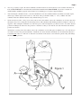
Texas T Parts
711 Ashford Hills Drive
Bryan, Texas 77801
(979) 260-5433 1-800-337-6977
Fax (979) 260-1214
www.TexasTParts.com
Distributor Installation Instructions
Item# T3161
Revised November, 2013
NOTE: Please read completely through the instructions before installing your distributor. That will insure your installation goes smoothly.
Your distributor kit should include the following components:
Distributor Assembly
Control Rod with 1 end attached
1 - 3/8"-24 / 3/8"-16 X 5-1/2" Stud
1 - 3/8"-16 Hex Nut
1 - 3/8"-24 X 2-1/2" Bolt
(used on early cars without a generator)
1
2
3
1
1
10 mm Combination Wrench
5/16" Combination Wrench
3/8" Combination Wrench
9/16" Combination Wrench
7/8" Combination Wrench
Bearing Grease
Ohmmeter
Tools & Supplies required for the installation of your Distributor:
Recommended Ignition Point Gap .015”-.020”
1.
2.
3.
-
3/8"-24 X 1-1/4" Bolt
3/8" Flat Washer
3/8" Lock Washers
Camshaft Gear
7/16" Half Nut
Recommended Spark Plug Gap .035”-.040”
You may want to drain and remove your radiator for the installation of this distributor the first time. With the 3/8"-24 X 5-1/2"
Stud that is provided with this kit, it will no longer be necessary to remove the radiator, but doing so makes it much easier to
access the engine and install the distributor on the initial installation.
Process Preview: On later model cars (1919 - 1927) if you do not remove the radiator, it will be necessary to
remove the commutator case bolt (T3162B) by loosening the bolt and sawing it in two with a hacksaw while holding it
with Vice Grips® or other locking pliers. After sawing the commutator case bolt in two pieces and removing them,
you will also need to remove the generator or alternator so that you can slide the 5-1/2" stud into position from the
back side to replace the bolt that has just been removed. After installing the 5-1/2" stud, it will not be necessary to
remove either the radiator or the generator in the future if it is ever necessary to remove the distributor.
Remove the timer (commutator), roller, control rod, and timer spring arm. Remove the timer wires, they will no loonger be used.
Clean the timing gear cover plate where the distributor will be installed. Remove the brass shield behind the timer roller or brush if
there is one. It is no longer needed.
IMPORTANT: Your timing gear cover plate must be properly aligned with your cam shaft (Model T Ford Service Manual, p.
120). If you are not sure this was done when your engine was assembled, it is very wise to do it at this time. It is possible for
a mis-aligned timing cover to cause damage to your distributor when you try to start your engine. Damage due to improper
installation will void your warranty. If you do not have a timing gear cover alignment tool, Texas T Parts offers one as Item
#T3009-T. It is included with our Distributor Installation Kit, Item #T3161K. At the very least, visually inspect to determine
that the camshaft is well centered within the hole of the timing gear cover plate where the camshaft seal goes.
4.
5.
6.
Page 2
Now is a good time to replace the old felt camshaft seal with a modern seal. The modern oil seal is available from Texas T
Parts as Item T3177-OS or is included with our Distributor Installation Kit, Item #T3161K. If you have a modern seal
installed and the camshaft is properly centered in the seal, your timing gear cover plate is properly aligned.
After checking the camshaft for burrs, screw the Camshaft Gear onto the camshaft, with the wrench flats toward the engine,
until it stops, and the engine starts to turn over. The front of the gear should be flush ( +/- 1/16" ) with the end of the
camshaft. Insure the distributor mounts easily, without having to use force.
On later model cars (1919 - 1927), if you do not want to remove the radiator, remove the commutator case bolt (Location A in
the figure below) by loosening the bolt and sawing it in two with a hacksaw while holding it with Vice Grips® or other locking pliers. After sawing the commutator case bolt in two pieces and removing them, you will also need to loosen the other two
generator mounting bolts and remove the generator or alternator so that you can slide the 3/8" stud in from the back and into
position at location A.
Alternatively, you may remove the radiator, remove the commutator case bolt and replace it with the new 5-1/2" stud and you
do not have to remove the generator/alternator. Install the 3/8" stud so that the end with the 3/8"-24 national fine threads, is
toward the back of the car. If the 3/8"-16 national coarse threads of the stud are screwed into the generator they will damage
the threads in the generator.
Figure 1
7.
8.
9.
Page 3
After inserting the 3/8" stud into the location designated, re-install the generator (or alternator). The short generator mounting bolts
should be tightened after the new 3/8" stud has been screwed into the generator/alternator housing by hand. The stud should then
be screwed into the generator approximately 10 threads (1/2"). The end of the stud toward the front of the car will have about 7/8"
of threads and a 1/2" long nub on the end to allow you to grab it with a pair of pliers when needed. After installing the 5-1/2"
stud, it will not be necessary to remove either the radiator or the generator in the future in order to remove the distributor.
Fill the gear cavity in the distributor housing about 2/3 full of grease. Turn the distributor head within the lower end of the
body until the condenser and condenser wire are to the rear of the distributor - away from the fan blade. Also, if the distributor
is installed with the condenser straight forward, the distributor head can come out of the adapter casting and your car will not
run. (That really won’t matter however because once the fan blade wipes out the condenser the car wouldn’t run anyway.)
Place the distributor assembly into the recess on the front of the timing gear cover plate from which the timer was removed.
See Figure 1. Note: The 3” round protrusion on the back of the distributor extends out about 3/16” but the recess in the timing
gear cover plate that it fits into is usually only 3/32” deep. The distributor is not designed nor intended to slip completely into
the recess on the timing gear cover plate. The recess is not usually as deep as the projection on the distributor.
Place the distributor into place over the 3/8" Stud and install the flat washer, lock washer and 3/8" nut to mount the distributor
housing. For early engines without generators use the 3/8" X 2-1/2" bolt provided instead of the 3/8" stud. When you press the
base of the distributor against the front of the engine into the recess where the camshaft is, there may be a gap between the mounting tab on the distributor and the mounting surface that the bolt goes thru. You may use a washer or two as spacers to fill the gap.
Optional Support: Remove the timer cover bolt that is directly to the right (shown at B). Using the 7/16" nut supplied as a
spacer, and using the 3/8" X 1-1/4" bolt and lock washer supplied, install the timer spring arm upside down (shown at C), on
the flat surface of the distributor. This will provide additional support to the distributor.
10. Connect the control rod to the clamp on the distributor and to the spark lever rod end. Position the control rod (shown at D). Bend
it up or down depending on your lower radiator hose location so it has smooth operation as you work the spark lever through its
normal range. You may find it necessary to bend the rod slightly. Tighten the lock nuts. Leave the lever on your steering column
in the up (retarded) position. Do not tighten the control arm clamp on the distributor at this time- you must set the timing first.
11.
12.
13.
13A.
13B.
14.
Before proceeding check the point gap and if necessary set the gap to .016" to .020". If using electronic ignition, ignore this step.
Position your Number 1 cylinder (Front) at Top Dead Center on the compression stroke. (Uppermost travel of the piston with
both valves closed, as the piston rises). By placing your thumb over the #1 spark plug hole as you turn over the engine by
hand you will know if the engine is on the compression stroke if the piston pushes air out of the spark plug hole.
Install your ignition coil in your car. I have received many calls regarding “Where should I instal my ignition coil?” There is
no single answer to that question. It does not matter where the coil is installed so long as it is close enough for the coil wire to
reach from the coil to the distributor cap. In 26-27 cars with the original coil box installed on the head of the engine, I like to
put the modern coil inside the old coil box. Earlier cars may have it attached to the frame on the right hand side of the car or
installed on a home-made bracket held under a head bolt on the engine. (Be sure you have enough threads on the head bolt
going into the block so that you don’t strip the threads in the block however.) Wherever you install your modern ignition coil,
connect the wire going to the bottom terminal of your old coil box to the positive (+) terminal of the new ignition coil.
If using points and a condenser, use an ohmmeter or circuit tester attached between the condenser lead (green wire) and ground,
rotate the distributor head clockwise, until the points start to open. When the meter first shows an open circuit it has reached the
firing point. Without moving the distributor head, tighten the nut on the control arm clamp. You will need a 10mm wrench.
CAUTION: Over tightening will distort the clamp and cause binding! The green wire from the condenser on the distributor
head is to be connected to the negative (-) terminal of the ignition coil. Go to step 14.
If using an electronic ignition module, (or as an alternate method with points and a condenser) connect the coil (as outlined
in step 14) and lay the hi-voltage lead from the coil to the cylinder head leaving about a 1/4" gap between the wire and the
head. With the ignition turned ON rotate the distributor head clockwise slowly until the coil fires. This your Firing Point.
Without moving the distributor head, tighten the nut on the control arm clamp. You will need a 10mm wrench. CAUTION:
Over tightening will distort the clamp and cause binding!
Remove the distributor cap, and note the position of the rotor. When your first cylinder is at top-dead-center on the compression
stroke, this is the Number 1 firing position. It is a good idea to mark the outside of the distributor head. The distributor rotor
turns counter-clockwise. The firing order for a Model T is 1 - 2 - 4 - 3. Connect your spark plug and coil wires. The ignition
wire (small green wire) from the distributor head goes to the negative side of the coil.
NOTE: On electronic ignition, the black wire goes to the negative (-) coil terminal and the red wire goes to the positive (+)
coil terminal. If you are using a coil requiring an external resistor (not sold by us), it needs to go to the high side of the resistor.
Page 4
15. Although the fan arm on pre-’26 models may be adjusted as manufactured, you may find it easier to adjust if the adjusting bolt is
removed, the head cut off, and a slot cut across the end. This allows it to be adjusted with a screwdriver, making it somewhat easier.
16.
For best performance, the spark plugs should be set to a .040" gap.
Points gap should be set at .016 to .020.
17. Before replacing the radiator, it is a good idea to give the engine a test fire, then replace the radiator, and go for a ride with confidence.
Do not run the engine long without a radiator if you have a waterpump with a modern seal. Modern waterpump seals should not be run when dry.
Note Added 2/1/2012:
GROUNDING THE DISTRIBUTOR
The distributor should be grounded adequately to the frame of the car thru both the base and the control rod but we have had several
reports from individuals who have experienced some intermittent misfires that were resolved by attaching a dedicated ground wire
under the screw that holds the condenser in place and grounding the other end under another screw on the engine or frame. This
grounding may be unnecessary but it is easy to do and would have no negative effects.
MAINTENANCE
Your Texas T Parts distributor requires very little maintenance. The drive gears should be repacked every 10,000 miles. The shaft
bearings are sealed and permanently lubricated, and require no maintenance. The distributor head should be oiled every 1,000 miles.
The oil hole is to the left of the monogram.
SERVICE
Although this unit uses a custom made distributor head, the points, condenser, rotor, and distributor cap will interchange with distributors commonly used for production vehicles. We do stock replacement parts. For easy service remove the retainer screw just
below the distributor head and to the right of the monogram. After disconnecting the control rod, the head may be removed for servicing and reinstalled without losing your timing setting. The head is keyed and will only fit in one position.
If you like our product, tell your friends. If you have a question not covered by these instructions, give us a call.
Even though we sell points, condensers, distributor caps and rotors, we are concerned about your convenience after you have
installed one of our distributors. In case you have a need to purchase any of the above replacement parts while touring we are giving
you the Texas T Parts part number and the NAPA Auto Parts part number so you will never be stranded. We recommend carrying
replacement parts regardless of where you purchase them.
Ignition Points (.015-.020 gap)
Condensor
Distributor Cap
Distributor Rotor
Thanks and Smooth Running,
TEXAS 'T' PARTS
TTP Part #
NAPA Part #
T3161Points (JF4)
CS313SB
T3161Points (VW07)
(Latest Version)
T3161Cond
T3161Cap
T3161Rotor
CS314
EP466
EP274SB
EP278SB
(Clips holding the distributor cap will
be held on with machine screws.)
(Clips holding the distributor cap will
be held on with pop rivets.)
LIMITED WARRANTY
Texas ‘T’ Parts will repair or replace any part that we manufacture, for a period of 90 days from the date of purchase, that wears out or breaks.
Since we don’t install parts, the part must be installed on the type of individually owned and operated passenger vehicle for which it is
designed. Of course, we cannot replace a part whose failure was caused by another faulty part, low fluid, or other abuse.
Return any part directly to us, along with a copy of the sales receipt showing the date of purchase, and $10 to cover shipping & handling. Do not return parts to your dealer.
That’s what our warranty means in plain English, but we regret we must include this legalese, too: THIS LIMITED WARRANTY REPRESENTS
THE TOTAL LIABILITY OF TEXAS ‘T’ PARTS FOR ANY WARRANTED PART, AND TEXAS ‘T’ PARTS MAKES NO OTHER WARRANTIES, EXPRESS OR IMPLIED, INCLUDING THE IMPLIED WARRANTIES OF MERCHANTIBILITY OR FITNESS FOR A PARTICULAR PURPOSE. TEXAS ‘T’ PARTS SHALL NOT BE LIABLE FOR ANY INDIRECT, SPECIAL, INCIDENTAL, OR CONSEQUENTIAL
DAMAGES. Texas ‘T’ Parts reserves the right, at its option, to refund the customer’s money instead of replacing a part. This warranty does not
cover parts that are installed on marine, off-road, commercial, or government vehicles, or stationary units.
7H
[
D
V
7
3D
U
W
V
$V
KI
RU
G
+L
O
O
V
'U
L
YH
%U
\D
Q
7;