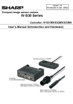
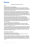
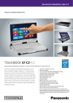
1
SERVICE MANUAL Part No Product Name 98TP10I8Z00E Revision 110 10.1” Rugged Tablet Model Name Station M101BC Product Name:10.1” Rugged Tablet Model Name: M101BC 1 (DO NOT COPY OR DISTRIBUTE WITHOUT PERMISSION) FMRD033C SERVICE MANUAL Document History Item Date Revision Description 1 2014.12.03 1.0 New Document Released 2 2014.12.16 1.1 1) Electric Screwdriver Torque Calibration Standard Procedure 2) Board Dispensing Standard Operation Procedure 3 4 5 6 7 8 9 10 11 12 13 14 15 16 Approved by Reviewed by Made by Brian John Cash 2 (DO NOT COPY OR DISTRIBUTE WITHOUT PERMISSION) FMRD033C SERVICE MANUAL Table of Contents Section 1: Exploded‐view Drawing ................................................................................................................ 5 Section 2: Spare Parts List for Service ............................................................................................................ 6 Section 3: Trouble Shooting Flowchart .......................................................................................................... 7 Chapter 3.1 No Boot ...................................................................................................................................... 7 Chapter 3.2 No OS Loading ............................................................................................................................ 8 Chapter 3.3 Panel Malfunction ...................................................................................................................... 9 Chapter 3.4 Charging/Discharging Malfunction .......................................................................................... 10 Chapter 3.5‐Touch Malfunction ................................................................................................................... 11 Chapter 3.6 ‐Front/Rear Camera Malfunction ............................................................................................. 12 Chapter 3.7 WiFi/BT Malfunction ................................................................................................................ 13 Chapter 3.9 GPS Malfunction ...................................................................................................................... 15 Chapter 3.10 ‐USB Malfunction ................................................................................................................... 16 Chapter 3.11‐ Audio Jack Malfunction ........................................................................................................ 17 Section 4: Replacement Procedure.............................................................................................................. 20 Replace Rear Cover Kit (I) ............................................................................................................................ 20 Replace Front Bezel Kit (I) ............................................................................................................................ 24 Replace WIFI&BT Module (I) ........................................................................................................................ 28 Replace SSD (I) ............................................................................................................................................. 33 Replace Battery (I) ........................................................................................................................................ 37 Replace Barcode Reader (I) .......................................................................................................................... 39 Replace WWAN Module (I) .......................................................................................................................... 47 Replace Mainboard (I) ................................................................................................................................. 51 Replace GPS Antenna (I) ……………………………………………………………………………………………….……………………….58 Clear CMOS (I ............................................................................................................................................... 61 BIOS update (Windows 8 series) (I) ............................................................................................................. 62 BIOS update (Windows 7 Series)(I) .............................................................................................................. 63 One‐Key Recovery ........................................................................................................................................ 64 2M Camera setup (I) .................................................................................................................................... 65 5M Camera setup (I) .................................................................................................................................... 68 WIFI&BT setup (I) ......................................................................................................................................... 71 GPS setup (I) ................................................................................................................................................. 73 Volume adjustment setting (I) ..................................................................................................................... 74 Barcode Reader setup (I) ............................................................................................................................. 75 Appendix A: Electric Screwdriver Torque Calibration Standard Procedure ................................................. 78 Appendix B: Board Dispensing Standard Operation Procedure .................................................................. 85 3 (DO NOT COPY OR DISTRIBUTE WITHOUT PERMISSION) FMRD033C SERVICE MANUAL 4 (DO NOT COPY OR DISTRIBUTE WITHOUT PERMISSION) FMRD033C SERVICE MANUAL Section 1: Exploded‐view Drawing 5 (DO NOT COPY OR DISTRIBUTE WITHOUT PERMISSION) FMRD033C SERVICE MANUAL Section 2: Spare Parts List for Service Item Part Number Spare Part Note 1 98S010A0000X Front Cover 2 98K010A00016 Rear Cover 3 98K000A0004N M/B Kit 4 76E064300502 SSD 64GB 4 76E128300501 SSD 128GB 5 72MB4GA0001G RAM 4GB 5 72MB8GA0000G RAM 8GB 6 9B0000000298 WiFi+BT Card 7 9B0000000386 Front Webcam 8 9B000000001Z Rear Webcam 9 98K000A00041 Intermec BR 10 320407405002 Battery(7.4V / 330mAh) 11 98K000A0004H Battery (7.4V / 5300mAh) Note: For the detail spare parts information, please refer to “98TP10I8Z00E_Spare_Parts__V100_EN.xlsx” 6 (DO NOT COPY OR DISTRIBUTE WITHOUT PERMISSION) FMRD033C SERVICE MANUAL Section 3: Trouble Shooting Flowchart Chapter 3.1 No Boot 7 (DO NOT COPY OR DISTRIBUTE WITHOUT PERMISSION) FMRD033C SERVICE MANUAL Chapter 3.2 No OS Loading 8 (DO NOT COPY OR DISTRIBUTE WITHOUT PERMISSION) FMRD033C SERVICE MANUAL Chapter 3.3 Panel Malfunction 9 (DO NOT COPY OR DISTRIBUTE WITHOUT PERMISSION) FMRD033C SERVICE MANUAL Chapter 3.4 Charging/Discharging Malfunction 10 (DO NOT COPY OR DISTRIBUTE WITHOUT PERMISSION) FMRD033C SERVICE MANUAL Chapter 3.5‐Touch Malfunction 11 (DO NOT COPY OR DISTRIBUTE WITHOUT PERMISSION) FMRD033C SERVICE MANUAL Chapter 3.6 ‐Front/Rear Camera Malfunction 12 (DO NOT COPY OR DISTRIBUTE WITHOUT PERMISSION) FMRD033C SERVICE MANUAL Chapter 3.7 WiFi/BT Malfunction 13 (DO NOT COPY OR DISTRIBUTE WITHOUT PERMISSION) FMRD033C SERVICE MANUAL Chapter 3.8 ‐WWAN Malfunction 14 (DO NOT COPY OR DISTRIBUTE WITHOUT PERMISSION) FMRD033C SERVICE MANUAL Chapter 3.9 GPS Malfunction 15 (DO NOT COPY OR DISTRIBUTE WITHOUT PERMISSION) FMRD033C SERVICE MANUAL Chapter 3.10 ‐USB Malfunction 16 (DO NOT COPY OR DISTRIBUTE WITHOUT PERMISSION) FMRD033C SERVICE MANUAL Chapter 3.11‐ Audio Jack Malfunction 17 (DO NOT COPY OR DISTRIBUTE WITHOUT PERMISSION) FMRD033C SERVICE MANUAL Chapter 3.12-Speaker Malfunction 18 (DO NOT COPY OR DISTRIBUTE WITHOUT PERMISSION) FMRD033C SERVICE MANUAL Chapter 3.13 ‐2D Barcode Reader Malfunction 19 (DO NOT COPY OR DISTRIBUTE WITHOUT PERMISSION) FMRD033C SERVICE MANUAL Section 4: Replacement Procedure Replace Rear Cover Kit (I) STEP 1 Item Material details: Step Assembly operations Description: 1 Unlock battery latch (marked in orange), take out the battery. 2 Remove Touch Pen, then release the screws (marked in yellow and blue). A Sequence Important note: 1 None STEP 2 20 (DO NOT COPY OR DISTRIBUTE WITHOUT PERMISSION) FMRD033C SERVICE MANUAL Replace Rear Cover Kit (II) STEP 1 Item Material details: Step Assembly operations Description: 1 Release Panel cable from the motherboard, such as in red box 2 Release Touch cable from the motherboard, as in the blue box. 3 Remove front Bezel Kit. STEP 2 Sequence Important note: 1 None STEP 3 21 (DO NOT COPY OR DISTRIBUTE WITHOUT PERMISSION) FMRD033C SERVICE MANUAL Replace Rear Cover Kit (III) STEP 1 Item Material details: Step Assembly operations Description: 1 Plug Touch cable in to Touch connector such as in the blue box on the motherboard, 2 Plug Panel cable in to the motherboard connector such as in the red box 3 Using round pan Philips head screws with M3x5mm (yellow ones) and M2x4mm (blue ones) to fix real cover kit on the front bezel kit, then, put the touch pen into the pen slot. STEP 2 Sequence Important note: 1 None STEP 3 22 (DO NOT COPY OR DISTRIBUTE WITHOUT PERMISSION) FMRD033C SERVICE MANUAL Replace Rear Cover Kit (IV) STEP 1 Item Material details: Step Assembly operations Description:: 1 Place the battery into the battery bay. Lock battery latches. Sequence Important note: 1 None 23 (DO NOT COPY OR DISTRIBUTE WITHOUT PERMISSION) FMRD033C A SERVICE MANUAL Replace Front Bezel Kit (I) STEP 1 Item Material details: Step Assembly operations Description: 1 Unlock battery latch (marked in orange), then take out the battery. 2 Remove Touch Pen, then release the screws, such as in the yellow & blue circles A Sequence Important note: 1 None STEP 2 24 (DO NOT COPY OR DISTRIBUTE WITHOUT PERMISSION) FMRD033C SERVICE MANUAL Replace Front Bezel Kit (II) STEP 1 Item Material details: Step Assembly operations Description: 1 Release Panel cable from the motherboard (marked in red). 2 Release Touch cable from the motherboard (marked in blue). 3 Removed "Front Bezel Kit" STEP 2 Sequence Important note: 1 None STEP 3 25 (DO NOT COPY OR DISTRIBUTE WITHOUT PERMISSION) FMRD033C SERVICE MANUAL Replace Front Bezel Kit (III) STEP 1 Item Material details: Step Assembly operations Description: 1 Plug Touch cable in to Touch connector (marked in blue) on the motherboard. 2 Plug Panel cable in to the motherboard connector (marked in red). 3 Using round pan Philips head screws with M3x5mm (yellow ones) and M2x4mm (blue ones) to fix rear cover kit on the front bezel kit, then, put the touch pen into the pen slot. STEP 2 Sequence Important note: 1 None STEP 3 26 (DO NOT COPY OR DISTRIBUTE WITHOUT PERMISSION) FMRD033C SERVICE MANUAL Replace Front Bezel Kit (IV) STEP 1 Item Material details: Step Assembly operations Description: 1 Place the battery in to the battery bay. Lock latches. Sequence Important note: 1 None 27 (DO NOT COPY OR DISTRIBUTE WITHOUT PERMISSION) FMRD033C A SERVICE MANUAL Replace WIFI&BT Module (I) STEP 1 Item Material details: Step Assembly operations Description: 1 unlock battery latches (marked in orange), take out the battery 2 Remove Touch Pen, and then remove the screws (marked in yellow and blue). A Sequence Important note: 1 None STEP 2 28 (DO NOT COPY OR DISTRIBUTE WITHOUT PERMISSION) FMRD033C SERVICE MANUAL Replace WIFI&BT Module (II) STEP 1 Item Material details: Step Assembly operations Description: Release Panel cable from motherboard (marked in red). 1 Release Touch cable from motherboard (marked in blue). Remove「Front Bezel Kit」and replaced 2 3 WIFI&BT Module Card, (marked in orange). *Refer to important note 1 STEP 2 Sequence Important note: 1 Main antenna connection wire is green; AUX antenna connection wire is yellow. The detailed setting of the main and AUX antennas for WIFI&BT modules is shown on the following page. STEP 3 AUX Main 29 (DO NOT COPY OR DISTRIBUTE WITHOUT PERMISSION) FMRD033C SERVICE MANUAL Replace WIFI&BT Module (III) STEP 1 Item Material details: A 9B0000000286 (WPER – 101GN) B 9B0000000298 (Intel 6235) C 9B000000002R (Intel AC7260) Step Assembly operations Description: 1 Main antenna setting for WIFI&BT module is marked in red square; AUX is marked in red circle. AB Sequence Important note: 1 None B C 30 (DO NOT COPY OR DISTRIBUTE WITHOUT PERMISSION) FMRD033C SERVICE MANUAL Replace WIFI&BT Module (IV) STEP 1 Item Material details: Step Assembly operations Description: 1 Plug Touch cable in to Touch connector marked in blue on the motherboard, 2 Plug Panel cable into the motherboard connector (marked in red). 3 Using round pan Philips head screws with M3x5mm (yellow ones) and M2x4mm (blue ones) to fix rear cover kit on to the front bezel kit, then, put the touch pen into the pen slot. STEP 2 Sequence Important note: 1 None STEP 3 31 (DO NOT COPY OR DISTRIBUTE WITHOUT PERMISSION) FMRD033C SERVICE MANUAL Replace WIFI&BT Module (V) STEP 1 Item Material details: Step Assembly operations Description: 1 Place the battery into the battery bay. Lock battery latches. Sequence Important note: 1 None 32 (DO NOT COPY OR DISTRIBUTE WITHOUT PERMISSION) FMRD033C A SERVICE MANUAL Replace SSD (I) STEP 1 Item Material details: Step Assembly operations Description: 1 unlock battery latches (marked in orange), take out the battery 2 Remove Touch Pen, and then remove the screws, marked in yellow & blue circles. 3 Release Panel cable from motherboard (marked in red). STEP 2 Sequence Important note: 1 None STEP 3 33 (DO NOT COPY OR DISTRIBUTE WITHOUT PERMISSION) FMRD033C SERVICE MANUAL Replace SSD (II) STEP 1 Item Material detail: Step Assembly operations Description: Take「Front Bezel Kit」off and put on the 1 table Release Touch cable from motherboard (marked in blue). Remove「Front Bezel Kit」and replaced 2 3 SSD Module Card (marked in orange). STEP 1 Sequence Important note: 1 None STEP 2 STEP 3 34 (DO NOT COPY OR DISTRIBUTE WITHOUT PERMISSION) FMRD033C SERVICE MANUAL Replace SSD (III) STEP 1 Item Material detail: Step Assembly operations Description: 1 Plug Touch cable in to Touch connector (marked in blue) on the motherboard, 2 Plug Panel cable in to the motherboard connector (marked in red) 3 Using round pan Philips head screws with M3x5mm (yellow ones) and M3x4mm (blue ones) to fix rear cover kit on the front bezel kit, then, put the touch pen into the pen slot. STEP 2 Sequence Important note: 1 The torque of fix screw, please follow Electric Screwdriver Torque Calibration Standard Procedure STEP 3 35 (DO NOT COPY OR DISTRIBUTE WITHOUT PERMISSION) FMRD033C SERVICE MANUAL Replace SSD (IV) STEP 1 Item Material details: Step Assembly operations Description: 1 Place the battery into the battery bay. Lock battery latches (marked in orange). Sequence Important note: 1 None 36 (DO NOT COPY OR DISTRIBUTE WITHOUT PERMISSION) FMRD033C A SERVICE MANUAL Replace Battery (I) STEP 1 Item Material details: Step Assembly operations Description: Unlock battery latch (marked in orange) Take out the battery. 1 A Sequence Important note: 1 None STEP 2 37 (DO NOT COPY OR DISTRIBUTE WITHOUT PERMISSION) FMRD033C SERVICE MANUAL Replace Battery (II) STEP 1 Item Material details: Step Assembly operations Description: 1 Prepare the new Battery 2 Place the battery into the battery bay. 3 Lock battery latches. A Sequence Important note: 1 None STEP 2 STEP 3 38 (DO NOT COPY OR DISTRIBUTE WITHOUT PERMISSION) FMRD033C SERVICE MANUAL Replace Barcode Reader (I) STEP 1 Item Material details: A Step Assembly operations Description: 1 Unlock battery latch, such as in the orange box. Take out the battery. 2 Remove the Touch Pen, and then remove the screws, marked in yellow & blue circles. A Sequence Important note: 1 STEP 2 None 39 (DO NOT COPY OR DISTRIBUTE WITHOUT PERMISSION) FMRD033C SERVICE MANUAL Replace Barcode Reader (II) STEP 1 Item Material details: Step Assembly operations Description: 1 Release Panel cable from motherboard (marked in red) 2 Release Touch cable from motherboard (marked in blue) 3 Remove the “Front Bezel Kit”, as in the orange box, Barcode reader STEP 2 Sequence Important note: 1 None STEP 3 40 (DO NOT COPY OR DISTRIBUTE WITHOUT PERMISSION) FMRD033C SERVICE MANUAL Replace Barcode Reader (III) STEP 1 Item Material details: Step Assembly operations Description: 1 Unplug Barcode Reader Cable, marked in red. 2 Remove Barcode Reader Module, marked in blue. Sequence Important note: 1 None STEP 2 41 (DO NOT COPY OR DISTRIBUTE WITHOUT PERMISSION) FMRD033C SERVICE MANUAL Replace Barcode Reader (IV) STEP 1 Item Material details: Step Assembly operations Description: 1 Replace with a complete Barcode Reader and daughter board as shown in the picture. *Refer to important note 1 2 Fix the Barcode Reader on to the rear cover as in the yellow box shown. 3 Stick the FFC on to the rear cover as shown in the picture. *Refer important note 2 STEP 2 Sequence Important note: 1 The outlet of the Barcode Reader is downward. 2 Set the wire of the FFC into the channel of the clapboard, instead of on top of the backup battery. STEP 3 42 (DO NOT COPY OR DISTRIBUTE WITHOUT PERMISSION) FMRD033C SERVICE MANUAL Replace Barcode Reader (V) STEP 1 Item Material details: Step Assembly operations Description: 1 Set the wire of the FFC is as the red box shown. *Refer important note 1 2 Attach the Decode Board by using the self‐tapping M2x5 round pan Philips head screws to the rear cover, as shown in the blue box. 3 Connect wire to the main board as in the orange box. STEP Sequence Important note: 1 When attaching the FFC wire, route through the guide channel, please attach to the top of GPS module with tape. STEP 3 43 (DO NOT COPY OR DISTRIBUTE WITHOUT PERMISSION) FMRD033C SERVICE MANUAL Replace Barcode Reader (VI) STEP 1 Item Material details: Step Assembly operations Description: 1 Set wire of the FFC as in the red box * Refer important note 1 2 Stick the CMOS battery back to the rear cover Sequence Important note: 1 When attaching the FFC wire, route through the guide channel, please attach to the top of GPS module with tape. STEP 2 44 (DO NOT COPY OR DISTRIBUTE WITHOUT PERMISSION) FMRD033C SERVICE MANUAL Replace Barcode Reader (VII) STEP 1 Item Material details: Step Assembly operations Description: 1 Plug Touch cable in to Touch connector such as in the blue box on the motherboard. 2 Plug Panel cable in to the motherboard connector such as in the red box 3 Use the round pan Philips head screws with M3x5mm (yellow ones) and M2x4mm (blue ones) to fix the rear cover kit on to the front bezel kit, then, put the touch pen into the pen slot. STEP 2 Sequence Important note: 1 None STEP 3 45 (DO NOT COPY OR DISTRIBUTE WITHOUT PERMISSION) FMRD033C SERVICE MANUAL Replace Barcode Reader (VIII) STEP 1 Item Material details: Step Assembly operations Description: 1 Set the battery into the battery slot, and lock with the battery latches. Sequence Important note: 1 None 46 (DO NOT COPY OR DISTRIBUTE WITHOUT PERMISSION) FMRD033C A SERVICE MANUAL Replace WWAN Module (I) STEP 1 Item Material details: A Step Assembly operations Description: 1 Open Service Window as shown in the red box. 2 Release the antenna wire as shown in the red box Sequence Important note: 1 None STEP 2 47 (DO NOT COPY OR DISTRIBUTE WITHOUT PERMISSION) FMRD033C SERVICE MANUAL Replace WWAN Module (II) STEP 1 Item Material details: Step Assembly operations Description: 1 Put WWAN module in to WWAN Slot 2 Attach antenna connection wire onto the WWAN module Sequence Important note: 1 Knowing the main connection position is required for WWAN module, please refer to the next page. STEP 2 48 (DO NOT COPY OR DISTRIBUTE WITHOUT PERMISSION) FMRD033C SERVICE MANUAL Replace WWAN Module (III) STEP 1 Item Material details: A 9B000000000A(MC8090) B 9B000000002F(MC7305) C 9B0000000365(MC7355) Step Assembly operations Description: 1 WWAN module Main connection locations, as shown in the red boxes. AB Sequence Important note: 1 None B C 49 (DO NOT COPY OR DISTRIBUTE WITHOUT PERMISSION) FMRD033C SERVICE MANUAL Replace WWAN Module (IV) STEP 1 Item Material details: Step Assembly operations Description: 1 Attach the back cover using the Phillips flat head M2x3mm screws on the Service Window. Sequence Important note: 1 None 50 (DO NOT COPY OR DISTRIBUTE WITHOUT PERMISSION) FMRD033C SERVICE MANUAL Replace Main board (I) STEP 1 Item Material details: A Step Assembly operations Description: 1 Unlock battery latch, such as in the orange box. Take out the battery. 2 Remove the Touch Pen, and then remove the screws, marked in yellow & blue circles. 3 Remove the antenna as shown in red box. A STEP 2 Sequence Important note: 1 None STEP 3 51 (DO NOT COPY OR DISTRIBUTE WITHOUT PERMISSION) FMRD033C SERVICE MANUAL Replace Main board (II) STEP 1 Item Material details: Step Assembly operations Description: 1 Release Panel cable from the motherboard, such as in red box 2 Release Touch cable from the motherboard, as in the blue box. 3 Remove conductive tape, and EMI material as shown in red box. STEP 2 Sequence Important note: 1 None STEP 3 52 (DO NOT COPY OR DISTRIBUTE WITHOUT PERMISSION) FMRD033C SERVICE MANUAL Replace Main board (IV) STEP 1 Item Material details: Step Assembly operations Description: 1 Remove the Mylar covering the battery 2 Remove the RF shielding foil. Be careful not to tear it. 3 Remove the 2M Camera, as shown in the red box. STEP 2 Sequence Important note: 1 None STEP 3 53 (DO NOT COPY OR DISTRIBUTE WITHOUT PERMISSION) FMRD033C SERVICE MANUAL Replace Main board (V) STEP 1 Item Material details: Step Assembly operations Description: 1 Remove the RF absorbing tape from the 5M Camera. 2 Camera Remove the screws as shown in the red circles, and remove the 5M camera. 3 Remove the camera cables that are connected to the main board as shown in the red box. STEP 2 Sequence Important note: 1 None STEP 3 54 (DO NOT COPY OR DISTRIBUTE WITHOUT PERMISSION) FMRD033C SERVICE MANUAL Replace Main board (VI) STEP 1 Item Material details: Step Assembly operations Description: 1 Remove the Extension FPC from the main board 2 Remove the RF Antenna cables from the connectors 3 Remove screws from the middle plate as shown in red circles. STEP 2 Sequence Important note: 1 None STEP 3 55 (DO NOT COPY OR DISTRIBUTE WITHOUT PERMISSION) FMRD033C SERVICE MANUAL Replace Main board (VII) STEP 1 Item Material details: Step Assembly operations Description: 1 Remove the conductive tapes as shown. 2 Remove the backup battery and GPS antenna cable connectors from the main board. 3 Melt the plastic sealer and water proof glue, then remove the middle plate STEP 2 Sequence Important note: 1 None STEP 3 56 (DO NOT COPY OR DISTRIBUTE WITHOUT PERMISSION) FMRD033C SERVICE MANUAL Replace Main board (VIII) Item Material details: STEP 1 Step Assembly operations Description: 1 Remove the middle plate (along with main board) in the direction shown in the red arrow. 2 Remove the screws that secure the main board to the middle plate, to free the main board. After replace main board, please follow SOP to assemble unit step by step. 3 Sequence Important note: 1 None 57 (DO NOT COPY OR DISTRIBUTE WITHOUT PERMISSION) FMRD033C Direction of removal STEP 2 SERVICE MANUAL Item Material details: A Replace GPS Antenna (I) STEP 1 Step Assembly operations Description: 1 Unlock battery latch, such as in the orange box. Take out the battery. 2 Remove the Touch Pen, and then remove the screws, marked in yellow & blue circles. 3 Remove the antenna as shown in red box. A STEP 2 Sequence Important note: 1 None STEP 3 58 (DO NOT COPY OR DISTRIBUTE WITHOUT PERMISSION) FMRD033C SERVICE MANUAL Item Material details: Replace GPS Antenna (II) STEP 1 Step Assembly operations Description: 1 Release Panel cable from the main board, such as in red box 2 Release Touch cable from the main board, as in the blue box. 3 Remove EMI material as shown in red box. STEP 2 Sequence Important note: 1 None STEP 3 59 (DO NOT COPY OR DISTRIBUTE WITHOUT PERMISSION) FMRD033C SERVICE MANUAL Replace GPS Antenna (III) Item Material details: Step 1 Step Assembly operations Description: 1. Remove GPS antenna cable connectors from the main board. 2. Then replace GPS antenna, please follow SOP to assemble unit step by step. Sequence Important note: 1 None Step 2 60 (DO NOT COPY OR DISTRIBUTE WITHOUT PERMISSION) FMRD033C SERVICE MANUAL Clear CMOS Setting (I) STEP 1 Step Testing Job Description: 1 Use the tweezers to tie the pins of C91 together in 3 seconds as figure. Sequence Important note: 1 None 61 (DO NOT COPY OR DISTRIBUTE WITHOUT PERMISSION) FMRD033C SERVICE MANUAL BIOS update (Windows 8 series) (I) STEP 1、2、3、4 Step Testing Job Description: 1 Connect HDMI Cable and external display. 2 Boot Win8 system. 3 Copy BIOS file onto the desktop Using the mouse. Click File folder click the file which is in the upper left corne 4 5 Open command promptopen command as administratoryesupdate When Update process is finished. Reboot unit. STEP 5 Sequence Important note: 1 None 62 (DO NOT COPY OR DISTRIBUTE WITHOUT PERMISSION) FMRD033C SERVICE MANUAL BIOS update (Windows 7 Series)(I) STEP 1、2、3、4 Step Testing Job Description: 1 Connect HDMI Cable and external display. 2 Copy BIOS file in to USB driver. 3 Plug in USB driver which has bios files and OS Boot up, press Delete key, go in to BIOS setup menu Select Save & Exit → Boot Override →UEFI: 4 5 Built‐in EFI Shell Check the location of USB, the USB is in FS3. Key in FS3:press Enter, key in“cd XX 6 (The located BIOS file) 7 Key in update. Wait until update process End. 8 Reboot unit. STEP 6 Sequence Important note: 1 None STEP 6 STEP 7 63 (DO NOT COPY OR DISTRIBUTE WITHOUT PERMISSION) FMRD033C SERVICE MANUAL One‐Key Recovery Step Testing Job Description: 1 Plug‐in the AC adapter to M101B tablet computer. Make sure the M101B tablet computer stays plugged in to power source during the recovery process.. 2 Turn on the tablet computer, and when the boot screen shows up, press the Fn1 button (Recovery Key) on the front bezel OR press F6 when using an external USB keyboard to initiate the Recovery Wizard. 3 The following screen shows the Recovery Wizard. Click on “Recovery” button to continue. 4 A warning message about data loss will show up. Make sure data is backed up before recovery, and click on “Yes” to continue. 5 Wait till the recovery process to complete. During the recovery process, a command prompt will show up to indicate the percent of recovery process. After recovery is completed, and the tablet computer will restart Sequence Important note: 1 None 64 (DO NOT COPY OR DISTRIBUTE WITHOUT PERMISSION) FMRD033C STEP 1、2、3 STEP 4 STEP 5 SERVICE MANUAL Step Testing Job Description: 2M Camera setup (I) STEP 1 1 Click Hot Tab (green box) 2 Click Device (green box) 3 Confirm Camera icon is orange (green box) Sequence Important note: 1 None STEP 2 STEP 3 65 (DO NOT COPY OR DISTRIBUTE WITHOUT PERMISSION) FMRD033C SERVICE MANUAL Step Testing Job Description: 2M Camera setup (II) STEP 1 1 Click Hot Tab 2 Click Settings 3 Select action of button as Function 1 or Function 2 *Refer important note 1 Sequence Important note: 1 Function 1 is front panel FN key, Function 2 is FN key on rear STEP 2 STEP 3 66 (DO NOT COPY OR DISTRIBUTE WITHOUT PERMISSION) FMRD033C SERVICE MANUAL 2M Camera setup (III) STEP 1 Step Testing Job Description: Click Camera icon, it’ll change to orange, 1 then, decide to open with short or long press. *Refer important note 1 2 Run by starting with Hot Tab or setting FN. 3 Click top left icon to confirm 2M Camera Sequence Important note: Short Press is just on click,Long Press 1 requires a longer time to enable function. STEP 2 STEP 3 67 (DO NOT COPY OR DISTRIBUTE WITHOUT PERMISSION) FMRD033C SERVICE MANUAL Step Testing Job Description: 5M Camera setup (I) STEP 1 1 Click Hot Tab 2 Click Device 3 Confirm the Camera icon is orange Sequence Important note: 1 None STEP 2 STEP 3 68 (DO NOT COPY OR DISTRIBUTE WITHOUT PERMISSION) FMRD033C SERVICE MANUAL Step Testing Job Description: 5M Camera setup (II) STEP 1 1 Click Hot Tab 2 Click Setting 3 Select action of button as Function 1 or Function 2 *Refer important note 1 Sequence Important note: 1 Function 1 is front panel FN key, Function 2 is FN key on rear STEP 2 STEP 3 69 (DO NOT COPY OR DISTRIBUTE WITHOUT PERMISSION) FMRD033C SERVICE MANUAL Step Testing Job Description: 5M Camera setup (III) STEP 1 1 Confirm camera icon is orange. Confirm Short Press or Long Press is enabled. * Refer important note 1 2 Use Hot Tab enable or setting FN key to enable the camera function. 3 Confirm 5M Camera is working correctly. Sequence Important note: 1 Function 1 is front panel FN key, Function 2 is back of tablet of FN key STEP 2 STEP 3 70 (DO NOT COPY OR DISTRIBUTE WITHOUT PERMISSION) FMRD033C SERVICE MANUAL Step Testing Job Description: WIFI&BT setup (I) STEP 1 1 Click Hot Tab 2 Click Device 3 Confirm Wi‐Fi and BT icon is orange. Sequence Important note: 1 None STEP 2 STEP 3 71 (DO NOT COPY OR DISTRIBUTE WITHOUT PERMISSION) FMRD033C SERVICE MANUAL Step Testing Job Description: 1 Click Hot Tab (green box) 2 Click Device (green box) 3 Confirm WWAN icon is orange WWAN setup (II) STEP 1 Sequence Important note: 1 None STEP 2 STEP 3 72 (DO NOT COPY OR DISTRIBUTE WITHOUT PERMISSION) FMRD033C SERVICE MANUAL GPS setup (I) Step Testing Job Description: 1 Click Hot Tab 2 Click Device 3 Confirm GPS icon is orange STEP 1 Sequence Important note: 1 None STEP 2 STEP 3 73 (DO NOT COPY OR DISTRIBUTE WITHOUT PERMISSION) FMRD033C SERVICE MANUAL Step Testing Job Description: Volume adjustment setting (I) STEP 1 1 Push the + ‐ button on back of unit 2 Display will pop up window showing the volume is changed Sequence Important note: 1 None STEP 2 74 (DO NOT COPY OR DISTRIBUTE WITHOUT PERMISSION) FMRD033C SERVICE MANUAL Step Testing Job Description: Barcode Reader setup (I) STEP 1 1 Click Hot Tab icon (green box) 2 Click Device icon as (green box) 3 Confirm Barcode icon is orange Sequence Important note: 1 None STEP 2 STEP 3 75 (DO NOT COPY OR DISTRIBUTE WITHOUT PERMISSION) FMRD033C SERVICE MANUAL Step Testing Job Description: Barcode Reader setup (II) STEP 1 1 Click Hot Tab icon (green box) 2 Click Setting icon (green box) 3 Select action of button as Function 1 or Function 2 *Refer important note 1 Sequence Important note: 1 Function 1 is front panel FN key, Function 2 is back of tablet of FN key STEP 2 STEP 3 76 (DO NOT COPY OR DISTRIBUTE WITHOUT PERMISSION) FMRD033C SERVICE MANUAL STEP Testing Job Description: Barcode Reader setup (III) STEP 1 1 Confirm Barcode icon is orange. Confirm Short Press or Long Press is enabled. * Refer important note 1 2 Use Hot Tab enable or setting FN key to enable the reader function. Sequence Important note: 1 Function 1 is front panel FN key, Function 2 is back of tablet of FN key STEP 2 77 (DO NOT COPY OR DISTRIBUTE WITHOUT PERMISSION) FMRD033C SERVICE MANUAL Appendix A: Electric Screwdriver Torque Calibration Standard Procedure 1. Purpose: Before assembling, make sure the torque of screwdrivers followed the standard procedure and product will not be damaged while assembling. 2. Standard Screw Torque Table: 2.1 LCD Assembly First, check if the definition of screw torque is in the Approval Sheet. define, please refer to the table below. (Unit: kgf .cm) No LCD Size Screw 1 ≥ 15” 4 ± 0.5 2 10”~15” 2.5 ± 0.5 3 < 10” 2 ± 0.5 2.2 HDD Assembly (unit: kgf.cm) Check if the torque definition is in the Approval Sheet. Item HDD SSD If the torque is not Torque If not, refer to the table below Size Torque 3.5" 6 ± 0.5 2.5" 4 ± 0.5 SSD 2 ± 0.5 2.3 Plastic Fan Assembly (unit: kgf .cm) Fan Partial Tapping Full Tapping T4 Self-Tapping Screw T5 Self-Tapping Screw 5.0 ± 0.5 7.0 ± 0.5 8 ± 0.5 9.5 ± 0.5 2.3.1Partial Tapping: When the length of thread is bigger than the depth of tapping, it’s called partial tapping. It is mainly used for thin fan (as the PIC below). 78 (DO NOT COPY OR DISTRIBUTE WITHOUT PERMISSION) FMRD033C SERVICE MANUAL 2.3.2 Full Tapping: When the length of thread is almost equal to the depth of tapping, it’s called full tapping. It is mainly used for thick fan (as the PIC below). 79 (DO NOT COPY OR DISTRIBUTE WITHOUT PERMISSION) FMRD033C SERVICE MANUAL 2.4 Screw Torque Reference Table (unit: kgf .cm) Material Aluminum / Aluminum Magnesium Alloy Steel, Iron (Including I/O Connector) Plastic embedded copper stud Plastics (fan not included) Screw Type M2 M2.5 M3 M4 M1.6 M2 M2.5 M3 M4 #6-32 (#6≒ 3.5mm) #4-40 (#4≒ 2.8mm) M3 plastic screw, hexagonal plastic pillar M1.6 M2 M2.5 M3 M4 #6-32 (#6≒ 3.5mm) M3 plastic screw、hexagonal plastic pillar T2 self-tapping screw T3 self-tapping screw T4 self-tapping screw Torque Value 2.0 ± 0.5 3.0 ± 0.5 4.0 ± 0.5 8.0 ± 0.5 1.5 ± 0.2 2.0 ± 0.5 3.0 ± 0.5 4.0 ± 0.5 8.0± 0.5 6.0 ± 0.5 4.0 ± 0.5 1.0 ± 0.2 1.5 ± 0.2 2.0 ± 0.5 3.0 ± 0.5 4.0 ± 0.5 8.0± 0.5 6.0 ± 0.5 1.0 ± 0.2 2.0 ± 0.5 5.0 ± 0.5 10.0± 0.5 Notes: 1. Standard Torque Tolerance Definition: 1.1 When the torque is less than 2kgf.cm, set the tolerance to ±0.2. 1.2 When the torque is in the range of 2~12 kgf.cm, set the tolerance to ±0.5. 1.3 When the torque is more than 12 kgf.cm, set the tolerance to ±1. 2. #4-40 indicates the major diameter inch #4 = 0.112”≒ 2.8mm. 3. #6-32 indicates the major diameter inch #6 = 0.138”≒ 3.5mm. 4. For the specification of screw (ISO Metric Screw Thread/Unified thread standard/British Standard Whitworth), Please refer to the Appendix. 5. To lock the plastic screws and hexagonal plastic pillars, please use low torque electric screwdriver. 80 (DO NOT COPY OR DISTRIBUTE WITHOUT PERMISSION) FMRD033C SERVICE MANUAL 3. Calibration Step 3.1 Appearance 3.2 Time: Before products go on the assembly line. Calibration should be done by trained staff and follow the electric screwdriver SOP. 3.3 Function Description: LCD Display Unit Switch Screwdriver Testing Socket Clear Measuring Mode 81 (DO NOT COPY OR DISTRIBUTE WITHOUT PERMISSION) FMRD033C SERVICE MANUAL 3.3 Operating Description: 3.3.1Press POWER ON, make sure LCD displays 00. If not, press clear to reset to 0. 3.3.2 Place the electric screwdriver onto the testing socket. 82 (DO NOT COPY OR DISTRIBUTE WITHOUT PERMISSION) FMRD033C SERVICE MANUAL 3.3.3 Turn the screwdriver on and make sure the LCD display follows Item 2- Standard Screw Torque Table (Follow the SOP If the torque has been defined in SOP). Adjust and test until correct. And take note in the torque measurement table. 4. Appendix 4.1 Appendix 1: Screw Specification Table (ISO Metric Screw Thread/Unified thread standard/British Standard Whitworth) 5. Forms: 5.1 Torque Measurement Table (FMPD040) 83 (DO NOT COPY OR DISTRIBUTE WITHOUT PERMISSION) FMRD033C SERVICE MANUAL Appendix 1: Screw Specification Table (ISO Metric Screw Thread/Unified thread standard/British Standard Whitworth) and Conversion Chart. 1. ISO Metric Screw Thread: Label by outer diameter (mm), ex: M4,M3,M2… 2. Unified thread standard: Label as “Major diameter number ‐ Threads per inch and Pitch number”, ex: #2‐56, #4‐40, #6‐32, #8‐32. Note: Major diameter number function (inches): 0.060”+ Major diameter number*0.013” (inches) Ex: #4: 0.060" + 4*0.013" =0.112" 3. British Standard Whitworth: Pound times foot (lbf‐ft,lbf‐in) The labeling method is as follow: First, set the denominator to 8, and then times the numerator. Ex: 1/8 x 0.50 –PPB: 1 thread x 0.50” inches, PPB 4. Conversion Chart 1 ft = 30.4cm, 1 lbf‐ft =13.83kgf‐cm, 1kgf =2.205lbf 1 lb = 0.454kg,1 kgf‐cm =0.8673 lbf‐in, 1N = 0.101972kgf 1N = 0.224809lbf 100Kgf‐cm=10N‐m=90lbf‐in 84 (DO NOT COPY OR DISTRIBUTE WITHOUT PERMISSION) FMRD033C SERVICE MANUAL Appendix B: Board Dispensing Standard Operation Procedure Technique Standard 0003 Technique‐Standard‐0003 I. Board Dispensing Standard 1. Jumper Dispensing Standard: a. Check the position of Jumper and Use the dispenser to secure the Jumper connection. Do not use the dispenser as below. Dispensing right on top of the Jumper will NOT secure it. × × 85 (DO NOT COPY OR DISTRIBUTE WITHOUT PERMISSION) FMRD033C SERVICE MANUAL Board Dispensing Standard Operation Procedure Technique‐Standard‐0003 2. Panel Cable Dispensing Standard: a. Mind the foolproof pin direction and location when fixing. See as figure A. b. When dispensing, glue the right and left end of the DF13 foolproof PIN. See as figure B. Figure A Figure B 86 (DO NOT COPY OR DISTRIBUTE WITHOUT PERMISSION) FMRD033C SERVICE MANUAL Board Dispensing Standard Operation Procedure Technique‐Standard‐0003 3. Connector Dispensing Standard: a. Make sure Cable is closely fitted and PIN is not off. Then, Use the dispenser on the foolproof PIN connection. DO NOT use the dispenser right in the center, for it will NOT touch the connecting point. × 87 (DO NOT COPY OR DISTRIBUTE WITHOUT PERMISSION) FMRD033C SERVICE MANUAL Board Dispensing Standard Operation Procedure Technique‐Standard‐0003 4. RAM Dispensing Standard: a. Make sure RAM is well fitted on the RAM socket. Avoid falling apart due to unfitting or vibration. Do NOT use the dispenser as the picture below. × 88 (DO NOT COPY OR DISTRIBUTE WITHOUT PERMISSION) FMRD033C Then use the Hot Glue Gun on the latch connection. SERVICE MANUAL Board Dispensing Standard Operation Procedure Technique‐Standard‐0003 5. HDD & CF Card Dispensing Standard: a. Make sure cable is closely fitted, then use the dispenser to connect the HDD and cable. b. Make sure the CF card is inserted, then use the dispenser on CF card and iron sheet to avoid falling apart. 89 (DO NOT COPY OR DISTRIBUTE WITHOUT PERMISSION) FMRD033C SERVICE MANUAL Board Dispensing Standard Operation Procedure Technique‐Standard‐0003 6. I –PEX Dispensing Standard Operation: a. Make sure everything is well-connected when fixing. b. When dispensing, make sure to connect with the board and avoid falling off from vibrating. A. Figure A 90 (DO NOT COPY OR DISTRIBUTE WITHOUT PERMISSION) FMRD033C See as figure SERVICE MANUAL Board Dispensing Standard Operation Procedure Assembly‐Standard‐0001 7. Fan Adaptor Dispensing Standard: a. Make sure Cable is closely fitted and well-connected, and then use Hot Glue Gun to secure. Do NOT use the dispenser at point that is not closely fitted. × 91 (DO NOT COPY OR DISTRIBUTE WITHOUT PERMISSION) FMRD033C SERVICE MANUAL Board Dispensing Standard Operation Procedure Assembly‐Standard‐0001 8. FFC Connector: a. Make sure FFC Connector is well-fixed in the latch. Bottom Contact Type Top Contact Type 92 (DO NOT COPY OR DISTRIBUTE WITHOUT PERMISSION) FMRD033C Then use Hot Glue Gun to secure.