1
LCT600
Belt Driven Leaf Collector
Owner's Manual
Safety Manual
Pre-Operating Manual
Operating Manual
Maintenance Manual
Service Manual
Parts Catalog
January 2014 edition
ODB Company
5118 Glen Alden Drive
Richmond, VA 23231
800-446-9823
www.leafcollector.com
LCT600
316021
DO NOT ATTEMPT TO OPERATE
OR REPAIR
THE LEAF COLLECTOR WITHOUT FIRST
READING AND UNDERSTANDING THIS
MANUAL
IF YOU HAVE ANY QUESTIONS CONCERNING THE
INSTALLATION OR OPERATION OF THIS UNIT, PLEASE CALL
ODB FOR ASSISTANCE BEFORE ATTEMPTING TO REPAIR OR
OPERATE THE UNIT.
IMPROPER USE OF ANY MACHINE CAN
RESULT IN SERIOUS INJURY!
STUDY AND FOLLOW ALL SAFETY
PRECAUTIONS BEFORE OPERATING OR
REPAIRING UNIT
THIS MANUAL IS AN INTEGRAL PART OF THE LEAF COLLECTOR AND SHOULD
BE KEPT WITH THE UNIT WHEN IT IS SOLD.
ODB COMPANY
5118 Glen Alden Drive
Richmond, VA 23231
800-446-9823
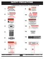
SAFETY PRECAUTIONS
Read and understand this entire manual before operating, maintaining or repairing the leaf vacuum.
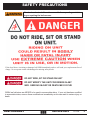
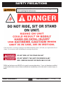
If the decal above is missing or damaged call ODB immediately and we will send you a replacement free of
charge. Never operate a unit with damaged or missing safety decals.
DO NOT RIDE, SIT OR STAND ON UNIT
DO NOT MODIFY THE UNIT FOR RIDERS IN ANY
WAY. SERIOUS INJURY OR DEATH MAY OCCUR
ODB’s leaf collectors are NEVER to be used to accomodate riders. If your unit has been modified
to accomdate riders, remove these modifications immediately as this can result in serious injury or
death.
ODB COMPANY
800-446-9823
LCT600
3
Municipal Products
Since 1910
Municipal Products
Since 1910
ODB COMPANY
5118 Glen Alden Drive
Richmond, VA 23231
800-446-9823
www.odbco.com or
www.leafcollector.com
THANK YOU
Thank you and Congratulations on your puchase of your ODB Leaf Collector. Your ODB leaf collector has been carefully designed and manufactured to give you a maximum amount of dependability and years of trouble-free operation. Take comfort in the fact the ODB has been manufacturing
municipal products since 1910 and takes pride in our product's quality and our customer service.
Please take the time to thoroughly read this manual, as well as the engine manual, in its entirety before operating, maintaining, servicing or repairing your leaf collector. Please thoroughly review and
follow all the safety procedures located in this manual.
Whenever you need replacement parts, service information or any question regarding your ODB
product please feel free to contact us at 800-446-9823 or www.odbco.com.
Please record the following information for future reference:
Model No.:
Serial No.:
Vin No:
Engine Serial No.:
Date of Purchase:
ODB COMPANY
800-446-9823
LCT600
4
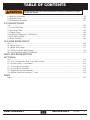
TABLE OF CONTENTS
Read and understand this entire manual before operating, maintaining or repairing the leaf vacuum.
Table of Contents
Contents
LCT600
Table of Contents
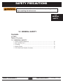
1.0 GENERAL SAFETY
1.1 Safety Symbol Definitions .....................................................................................................................10
1.2 Do’s and Do Not’s:................................................................................................................................. 11
1.3 Training:..................................................................................................................................................13
1.4 Safety Decals .......................................................................................................................................14
1.5 VIN And Serial Number Locations.........................................................................................................16
2.0 PRE-OPERATING SECTION
2.1 Instrument and Controls: ........................................................................................................................18
2.2 Safe Operations:......................................................................................................................................20
2.3 Preparation For Operation.......................................................................................................................22
2.4 Pre-Transport Checks..............................................................................................................................23
2.5 Personal Protective Equipment and Clothing.........................................................................................25
2.6 Work Site Preparation.............................................................................................................................26
3.0 OPERATING SECTION
3.1 Starting Engine........................................................................................................................................28
3.2 Engaging the PTO...................................................................................................................................30
3.3 Fluid Drive Coupler (if equipped)..........................................................................................................32
3.4 Vacuuming Leaves..................................................................................................................................33
4.0 MAINTENANCE SECTION
4.1 Maintence Overview:..............................................................................................................................35
4.2 Maintenance and Lubrication ................................................................................................................36
4.3 Lubrication:.............................................................................................................................................37
4.4 Preventative Maintenance.......................................................................................................................40
4.5 Torque Values..........................................................................................................................................44
5.0 SERVICE SECTION
5.1 Engine Electrical Troubleshooting Guide...............................................................................................48
5.2 Auto Mfg. Clutch Adjustment - 2008 and after......................................................................................49
5.3 Hydraulic Boom Troubleshooting Guide................................................................................................50
5.4 Impeller Installation and Removal..........................................................................................................51
5.4 Impeller Installation and Removal, continued........................................................................................52
5.5 Belt Adjustment and Replacement Guide...............................................................................................53
5.6 Flange Bearing Installation and Removal...............................................................................................54
5.6 Flange Bearing Installation and Removal...............................................................................................55
5.7 Replacing the Blower Housing Liners....................................................................................................56
5.7 Replacing the Blower Housing Liners; continued,��������������������������������������������������������������������������������57
5.10 WIRING DIAGRAMS
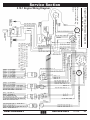
5.10.1 Engine Wiring Diagram.....................................................................................................................59
ODB COMPANY
800-446-9823
LCT600
5
TABLE OF CONTENTS
Read and understand this entire manual before operating, maintaining or repairing the leaf vacuum.
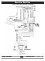
5.10.2 Engine Main Harness - Enlarged............................................................................................................ 60
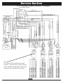
5.10.3 Auxillary Engine Harness - Enlarged..................................................................................................... 61
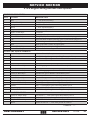
5.10.4 Engine Wiring Harness Descriptions...................................................................................................... 62
5.10.4 Engine Wiring Harness Descriptions, continued����������������������������������������������������������������������������������� 63
5.10.5 Engine Rocker Switch Wiring Diagrams................................................................................................ 64
5.10.6 Main Circuit Board................................................................................................................................. 65
5.10.7 Main Circuit Board Plug Diagrams........................................................................................................ 66
5.10.8 Trailer Plug Wiring Diagram.................................................................................................................. 67
5.10.9 Trailer Wiring Harness ........................................................................................................................... 68
5.10.10 Brake Wiring Harness .......................................................................................................................... 69
5.10.11 Boom Wiring Diagram.......................................................................................................................... 70
5.10.12 Remote Throttle / Clutch Wiring Harness ������������������������������������������������������������������������������������������ 71
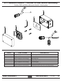
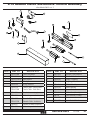
6.0 ENGINE GROUP
6-0...................................................................................................................................................................... 73
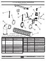
6.1 Instrument Panel Group .............................................................................................................................. 74
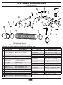
6.2 Air Cleaner Group........................................................................................................................................ 75
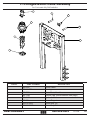
6.3 Strobe Light Parts Group............................................................................................................................. 76
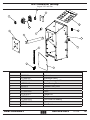
6.4 Sheet Metal Group....................................................................................................................................... 77
6.5 Engine Mount Group................................................................................................................................... 78
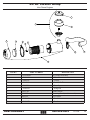
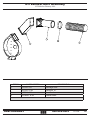
6.6 Muffler (Exhaust) Assembly........................................................................................................................ 79
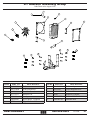
6.7 Radiator Assembly Group............................................................................................................................ 80
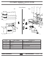
6.8 Engine Senders / Switch Group .................................................................................................................. 81
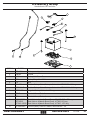
6.9 Battery Group............................................................................................................................................... 82
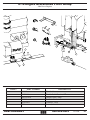
6.10 Engine Miscelleous Parts Group................................................................................................................ 83
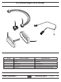
6.11 Remote Clutch / Throttle Circuit Board Assembly����������������������������������������������������������������������������������� 84
6.12 Remote Clutch and Remote Throttle Assembly���������������������������������������������������������������������������������������� 85
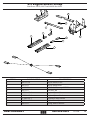
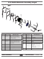
6.13 Chaffe Eliminator Assembly, hinged......................................................................................................... 86
7.0 CLUTCH GROUP
7-0...................................................................................................................................................................... 87
7.1 AutoHD PTO Clutch Group......................................................................................................................... 88
7.2 AutoHD PTO Assembly Group................................................................................................................... 89
7.3 AutoHD PTO Linkage Group...................................................................................................................... 90
7.4 Clutch Assist Group..................................................................................................................................... 91
7.5 Kraft Fluid Drive Group (Optional)............................................................................................................. 92
7.6 Kraft Fluid Drive Installation (Optional)..................................................................................................... 93
7.7 Kraft Fluid Drive Breakdown (Optional).................................................................................................... 94
7.8 Kraft Fluid Drive Common Parts (Optional)���������������������������������������������������������������������������������������������� 95
8.0 BLOWER HOUSING GROUP
8-0...................................................................................................................................................................... 96
8.1 Blower Housing Group................................................................................................................................ 97
8.2 Blower Housing Face Group - LCT600....................................................................................................... 98
ODB COMPANY
800-446-9823
LCT600
6
TABLE OF CONTENTS
Read and understand this entire manual before operating, maintaining or repairing the leaf vacuum.
8.3 Belt Drive Assembly...................................................................................................................................... 99
8.4 Pedestal Group............................................................................................................................................. 100
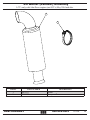
8.5 Exhaust Duct Assembly............................................................................................................................... 101
9.0 TRAILER GROUP
9-0...................................................................................................................................................................... 102
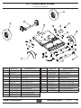
9.1 Trailer Bed Group........................................................................................................................................ 103
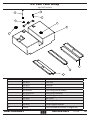
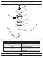
9.2 Fuel Tank Group.......................................................................................................................................... 104
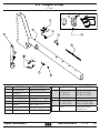
9.3 Tongue Group.............................................................................................................................................. 105
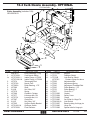
9.4 Hydraulic Parking Jack - OPTIONAL......................................................................................................... 106
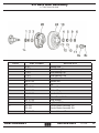
9.4 Axle Hub Assembly..................................................................................................................................... 107
9.5 Brake Assembly........................................................................................................................................... 108
10.0 HOSE BOOM GROUP
10-0.................................................................................................................................................................... 109
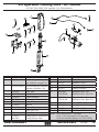
10.1 Boom Group.............................................................................................................................................. 110
10.2 Intake Hose Group..................................................................................................................................... 111
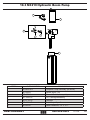
10.3 M3219 Hydraulic Boom Pump.................................................................................................................. 112
10.4 Curb Nozzle Assembly- OPTIONAL........................................................................................................ 113
MULTI-AXIS BOOM SECTION
(OPTIONAL)
11-0.................................................................................................................................................................... 114
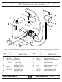
11.1 (2 or 3X) Hydraulic Tank - Valve Body Group����������������������������������������������������������������������������������������� 115
11.2 Joystick Group - 2 Axis Boom................................................................................................................... 116
11.3 (2 Axis) Boom Assembly .......................................................................................................................... 117
11.4 (3 Axis) Boom Assembly .......................................................................................................................... 118
11.5 Hinged Boom Frame Assembly................................................................................................................. 119
11.6 Auburn Gear Drive Assembly - 3 Axis...................................................................................................... 120
INDEX
Index.................................................................................................................................................................. 122
ODB COMPANY
800-446-9823
LCT600
7
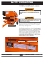
SAFETY PRECAUTIONS
Read and understand this entire manual before operating, maintaining or repairing the leaf vacuum.
If the decal above is missing or damaged call ODB immediately and we will send you a replacement free of
charge. Never operate a unit with damaged or missing safety decals.
DO NOT RIDE, SIT OR STAND ON UNIT
DO NOT MODIFY THE UNIT FOR RIDERS IN ANY
WAY. SERIOUS INJURY OR DEATH MAY OCCUR
ODB’s leaf collectors are NEVER to be used to accomodate riders. If your unit has been modified
to accomdate riders, remove these modifications immediately as this can result in serious injury or
death.
ODB COMPANY
800-446-9823
LCT600
8
SAFETY PRECAUTIONS
Read and understand this entire manual before operating, maintaining or repairing the leaf vacuum.
1.0
GENERAL
SAFETY
1.0 GENERAL SAFETY
Contents
LCT600
Table of Contents
1.0 GENERAL SAFETY
1.1 Safety Symbol Definitions ................................................................................ 10
1.2 Do’s and Do Not’s:............................................................................................ 11
1.3 Training:............................................................................................................. 13
1.4 Safety Decals .................................................................................................. 14
1.5 VIN And Serial Number Locations.................................................................... 16
ODB COMPANY
800-446-9823
LCT600
9
SAFETY PRECAUTIONS
Read and understand this entire manual before operating, maintaining or repairing the leaf vacuum.
1.1 Safety Symbol Definitions
This manual provides the owners/operator with procedures for safe operation, maintenance and repair of your leaf collector. As with any machine,
there are hazards associated with their operation. For this reason safety is
emphasized throughout this manual. To highlight specific safety information
the following safety definitions are provided to assist the reader.
The purpose of safety symbols are to attract your attention to possible
dangers. The safety symbols, and their explanations, deserve your careful attention and understanding. The safety warnings do not by themselves
eliminate any danger. The instructions or warnings they give are not substitutues for proper accident prevention measures.
MEANING
SYMBOL
SAFETY ALERT SYMBOL: Indicates danger, warning or caution. Attention is required in order to avoid serious personal injury. May be used in
conjuction with other symbols or pictographs.
Disregarding this safety warning WILL result in serious equipment
damage, injury or possible death.
Disregarding this safety warning CAN result in serious equipment
damage, injury or possible death.
Disregarding this safety warning MAY result in minor or moderate
injury or property damage.
ODB COMPANY
800-446-9823
LCT600
10
SAFETY PRECAUTIONS
Read and understand this entire manual before operating, maintaining or repairing the leaf vacuum.
1.2 Do’s and Do Not’s:
This section contains some general safety precautions to do and not to do.
This is not an all inclusive list and and it is the responsibilty of the operator to
have proper training and use common sense in work situations.
DO NOT:
1. DO NOT operate, maintain or repair this unit without having fully read and
understood ALL the aspects of this manual.
2. DO NOT ride, sit or stand on unit at anytime.
3. DO NOT modify the leaf vacuum for any reasons to allow for riders.
4. DO NOT operate the unit in a state of disrepair.
5. DO NOT operate the unit with ANY guards or safety devices broken, missing, or inoperable.
6. DO NOT operate the unit without wearing proper safety equipment.
7. DO NOT operate this unit while under the influence of any alcohol or medication.
8. DO NOT operate this unit if you have a record of mental instability or dizziness which could result in injury to yourself or others.
9. DO NOT operate this unit if you are under 18 years of age.
10.DO NOT operate this unit without fully inspecting the unit for any damage
or leakage.
11.DO NOT operate if the unit has any excessive vibration.
12.DO NOT operate unit with the inspection door limit switch damaged or
missing.
13.DO NOT operate unit unless it is properly connected to a leaf collection
box.
14.DO NOT operate unit unless it is properly attached to the tow vehicle.
15.DO NOT tow unit without using all the safety chains.
16.DO NOT tow unit with a damaged tongue.
17.DO NOT fill fuel tank with engine running. Allow engine to cool for 5 minutes before refueling.
18.DO NOT operate unit if fuel is spilled or with fuel cap off.
19.DO NOT smoke or weld near the unit.
20.DO NOT run engine in an enclosed area.
21.DO NOT place hands or feet near moving or rotating parts.
22.DO NOT operate engine with an accumulation of grass, leaves or other
debris on the engine.
ODB COMPANY
800-446-9823
LCT600
11
SAFETY PRECAUTIONS
Do Not, continued;
23.DO NOT run engine with air cleaner removed.
24.DO NOT leave leaf machine unattended while in operation.
25.DO NOT park machine on steep grade or slope.
26.DO NOT vacuum a leaf pile without looking for foreign objects such as
metal, glass, plastic or large pieces of wood.
Do’s:
1. DO completely read and understand the owner’s manual before operating,
maintaining or repairing the leaf collector.
2. DO follow engine and PTO manufacturer operating and maintenance instructions.
3. DO check fuel lines and fittings frequently for cracks or leaks. Replace if
necessary.
4. DO completely inspect the unit before leaving the service garage.
5. DO check the tow tongue each day for cracks.
6. DO inspect and be attentive to what is being vacuumed.
7. DO check the impeller, liners and blower housing for cracks or holes daily.
8. DO wear proper safety equipment as described in this manual.
9. DO watch for pedestrians, animals and other foreign material when vacuuming leaves.
10.DO replace any worn or missing safety stickers immediately.
ODB COMPANY
800-446-9823
LCT600
12
SAFETY PRECAUTIONS
1.3 Training:
Improper use of the ODB leaf collector CAN result in severe personal injury or death. All personnel using this leaf vacuum must
be trained and qualified with all the operations, maintenance, repair
and safety procedures defined in this manual.
The warnings and procedures regarding safety in this manual are to be
used as a guideline only. It is impossible to cover all the events that
could happen in the vacuuming process. For this reason, it is vital that
the owner accept the responsibility to implement a training program that
will provide every operator or mechanic the basic skills and knowledge to
make good judgement in all situations.
This training program must include the entire scope of hazards, precautions and government regulations encountered in the vacuuming process.
The program should stress the need for regularly scheduled preventive
maintenance and detailed equipment safety checks.
It is strongly recommended that all training programs be documented to
ensure all operators and mechanics receive initial training on not just the
operation but the safety features of the leaf collector.
ODB COMPANY
800-446-9823
LCT600
13
SAFETY PRECAUTIONS
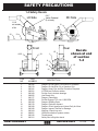
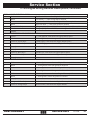
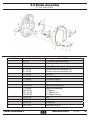
1.4 Safety Decals
5,6,7
Inside Pedestal
(2 of each)
LH Side
1,9,6
on outside
of lid
12
RH Side
11
13
1
14
Front
4,3,2
Rear
10
1
15
8
Decals
shown at end
of section
1.4
13
13
16
ITEM
NO.
1.
2.
3.
4.
5.
6.
7.
8.
9.
10.
11.
12.
13.
14.
15.
16.
ODB COMPANY
PART
NUMBER
200182
200179
200181
200221
200109
200055
200177
200059
200183
200178
200189
200180
200104
200061
200120
200112
DESCRIPTION
Danger--Do Not Open Cover While in Operation
Danger--Do Not Ride, Sit or Stand on Unit
Danger--Head, Eye and Ear Protection Required
LCT600 Leaf Collector sticker
Do Not Over-Lubricate bearings
Use Diesel Only
Danger--Flammable
Do Not Engage PTO over 1,000 RPM
Danger--Rotating Parts
Danger--Explosion Hazard
Danger--Check Impeller and Liners Daily for Wear
Danger--Inspect Tow Bar for Damage
Warning--Check Lug nuts
ODB leaf collection systems sticker
Throttle decal
Safety Shut off-Ignition decal
800-446-9823
LCT600
14
SAFETY PRECAUTIONS
1.4 Safety Decals - Decal Layout for LCT60C/600/650/6000
1
9
2
10
3
11
4
12
5
13
6
14
7
15
8
16
ODB COMPANY
800-446-9823
LCT600
15
SAFETY PRECAUTIONS
1.5 VIN And Serial Number Locations
figure 1.5a
Thoroughly read and understand the safety and preoperating sections of this manual before starting the
engine.
Serial Number Tag
Make sure each operator knows and understands the
load ratings of the towed vehicle and that he/she is
qualified to tow the vehicle.
VIN Number Tag
The serial number tag and Vehicle Identification Number
(VIN) sticker is located in front of the unit to the right of
the the tongue. (See figure 1.5a).
The VIN sticker gives the user critical information regarding the trailer specfications such as Gross Vehicle Weight
Rating (GVWR) which is the maximum allowable total
weight of the fully loaded trailer, including liquids, cargo
and the tongue weight of any towed vehicle, the GAWR
or Gross Axle Weight Rating which is the maximum allowable weight the axles are designed to carry. The tire
inflation pressure is also on the sticker.
Serial Number Tag
VIN Number Tag
ODB COMPANY
Tire and Load Information
800-446-9823
LCT600
16
2.0 PRE-OPERATING SECTION
Read and understand this entire manual before operating, maintaining or repairing the leaf vacuum.
2.0
Pre-Operating
Section
2.0 PRE-OPERATING SECTION
2.0 PRE-OPERATING SECTION
2.1 Instrument and Controls: ........................................................................................ 18
2.2 Safe Operations:...................................................................................................... 20
2.3 Preparation For Operation....................................................................................... 22
2.4 Pre-Transport Checks.............................................................................................. 23
2.5 Personal Protective Equipment and Clothing......................................................... 25
2.6 Work Site Preparation............................................................................................. 26
ODB COMPANY
800-446-9823
LCT600
17
Pre-Operating Section
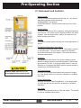
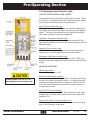
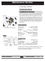
2.1 Instrument and Controls:
(Typical)
Ignition Switch:
Used to power the accessories and start the unit. Unit will not
start without Murphy switch depressed.
ACCESSORIES - first position
STARTER ENGAGE - second position (springs return to first
position)
Murphy Switch:
This switch overrides the low oil pressure and high temperature
cutoff control. This switch must be depressed before the starter
engages. After the engine starts, wait for oil pressure to rise
before releasing the button.
Throttle:
This control provides positive locking and vernier adjustment of
engine.
Combination Tachometer / Hour Meter:
This gauge indicates the engine r.p.m’s. The sender is located
on the tachometer. The hour meter is digital and indicates
the accumulated hours of the engine. This should be used to
schedule maintenance.
Volt Meter:
The gauge shows the status of the engine charging system.
When the charging system is operating properly it should read
approximately 14 volts. If the gauge reads below 13 volts, the
alternator is not charging the battery and the system should be
checked by a qualified technicican.
Always make sure the PTO is
disengaged before starting unit.
Oil Pressure Gauge:
Confirms and indicates the presense and pressure of engine
oil. If the gauge reads low, it should be checked by a qualified
technician.
Engine Temperature:
Indicates the engine coolant temperature. If the gauge reads
over 240 degrees the unit should be checked by a qualified
technician.
Hour Meter:
Indicates the accumulated hours of the the engine. This should
be used to schedule maintenance.
ODB COMPANY
800-446-9823
LCT600
18
Pre-Operating Section
2.1 Instrument and Controls, cont.:
SAFETY SWITCH INDICATOR LIGHTS
(Typical)
These lights work with the Murphy (safety) shut off switch. When
the light is on it indicates that the shut off switch has been tripped
and the light indicates which device caused the trip.
Low Oil Pressure Indicator Light:
When lit the engine has reached a low oil pressure reading and
has tripped (thus shut off the engine) the safety shut off (Muprhy)
switch . This light will illuminate when the engine is first started
until engine oil pressure has been established.
High Water Temperature Indicator Light:
Indicates the engine coolant temperature has reached 225 degrees and has tripped (thus shut off the engine) the safety shut off
(Muprhy) switch.
Inspection Door Indicator Light:
Indicates that the limit switch located on the blower housing inspection door has been tripped (thus shut off the engine).
Emergency Stop Switch Indicator Light:
Indicates that the emergency stop switch (on the LCT650 only)
has been depressed, tripping the safety switch and shutting off the
engine.
ROCKER SWITCHES
Strobe Light Switch:
Turns the strobe light on or off
Always make sure the PTO is
disengaged before starting unit.
Remote Throttle Switch (optional):
Increases or decreases the engine throttle. Pressing and holding
the top of the switch increases the thottle. The longer the button
is pressed the higher the throttle is advanced. Pressing the bottom of the switch decreases the throttle in the same manner as
increasing the throttle.
Remote PTO Switch (optional):
Engages or disengages the PTO. Pressing the top of the switch
engages the PTO while pressing the bottom of the switch disengages the PTO.
Engine Heat Switch (Cummins engines only):
Press the top of the switch for 20 – 30 seconds initiates the glow
plug to aid in starting a cold engine.
ODB COMPANY
800-446-9823
LCT600
19
Pre-Operating Section
2.2 Safe Operations:
ALL personnel using, maintaining or servicing this unit must be
trained in all safety procedures outlined in this manual. Improper
or careless use of this equipment CAN result in personal injury or
death.
Operations shall be restricted to:
1. Properly trained, qualified and experienced operators and/or qualified and
experienced maintenance and test personnel.
2. Trainees under the direct supervision of qualified and experience personnel.
3. Qualified and experienced maintenance and service personnel.
Operators who qualify to operate this equipment under the above restrictions shall also comply with the following physical requirements:
1. Have good vision and the ability to read and understand this manual as
well as all safety and operational decals on the equipment.
2. Be capable of hearing, with or without a hearing aid, at a level needed to
safely operate this equipment.
3. A record of mental stability with no history of epileptic seizures, dizziness,
or any other disability that may result in injury to himself or others.
If any of these requirements are not satisfied at any time, the person failing to
meet these requirements MUST NOT OPERATE THIS EQUIPMENT.
ODB COMPANY
800-446-9823
LCT600
20
Pre-Operating Section
2.2 Safe Operations (continued):
Additional Requirements:
1. Each operator must demonstrate competence to understand all safety
decals, operator’s manuals, safety codes, applicable government
regulations, and all other information applicable to the safe and proper
operation of the leaf vacuum.
2. Each operator must demonstrate the ability to recognize an emergency
situation that may arise during vacuuming operations and the knowledge and procedures to implement corrective action.
3. Each operator must demonstrate or provide evidence of qualificatation
and experience prior to operating the leaf vacuum.
4. Each operator must be able to recognize existing or potential problems
regarding the mechanical integrity of the leaf vacuum and report any
maintenance requirements to the supervisor in charge.
5. Each operator must wear the proper personal clothing and safety gear.
(Refer to SAFETY PRECAUTIONS Section 5.4)
6. Operators must not be physically or mentally fatigued.
7. Operators must not be under the direct or indirect influence of alcohol
and/or drugs. This includes prescription drugs that could cause drowsiness, dizziness, or any other condition that would impair their ability to
operate or use this equipment in a safe manner.
ODB COMPANY
800-446-9823
LCT600
21
Pre-Operating Section
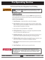
2.3 Preparation For Operation
Before your leaf vacuum is put into operation it is very important
to read and follow the procedures outlined in the engine owner’s
manual. (EOM).
For specific information regarding the following checks please refer to the
“Maintenance” section of this manual and the engine owner’s manual.
DISENGAGE the clutch and remove the negative battery cable before performing the following checks.
NEVER place any part of the body under or behind guards or any
other area in which you cannot see.
IMPORTANT CHECKS:
NOTE: The following checks contained in the next three sections should be
performed prior to leaving the storage area.
1.
2.
3.
4.
5.
6.
Check engine fuel, coolant and oil levels. (see EOM)
Check engine air filter
Check all bolts and nuts to ensure they are tight.
Check all controls for free and proper operation.
Check main drive belt (if equipped) for proper adjustment.
Inspect the fan blades to ensure that they are not bent , deformed, fatiqued
or cracked. Replace fan if any damage is present.
7. Inspect the intake hose flange to make sure it is connected correctly to the
blower housing.
8. Inspect the leaf vacuum frame and structure for any bent, broken, cracked,
missing or loose parts.
9. Check all guards to ensure they are undamaged, in place and properly
secured.
10.All decals must be in place and legible prior to operating the leaf vacuum.
See the decal section for decal replacement.
ODB COMPANY
800-446-9823
LCT600
22
Pre-Operating Section
2.4 Pre-Transport Checks
Failure to properly hitch the leaf vacuum to the tow vehicle, verify
the road worthiness of the leaf vacuum and the tow vehicle and
verify all equipment is properly stowed, may cause serious injury or
death to yourself or others.
TOW VEHICLE MUST have proper towing capacity for the leaf vacuum being towed. Check the tow vehicles operating manual for rated
capacity.
Do not tow the leaf vacuum unless all important checks listed below
are completed.
IMPORTANT CHECKS
1. Hitch is properly secured to tow vehicle and hose boom secured.
Frame must be level or the tongue slightly lower than the rear of the leaf
vacuum while towing to ensure proper weight distribution. The hitch may
have to be adjusted when towing with vehicles of varying tow hitch height.
2. Safety chains installed correctly.
3. Chains routed under trailer tongue in an “X” pattern between tow vehicle and
trailer.
4. Slack in chain should be adjusted to permit turning but should not be dragging on the ground.
5. Connect trailer wiring to the tow vehicle and ensure that all trailer lighting is
operating properly.
6. Ensure that the safety breakaway switch is functioning properly and attached
securely to the tow vehicle. Allow enough slack to ensure that vehicle turns
will not activate the safety breakaway switch. NOTE: Follow manufacturers
procedure to ensure tow vehicles brake control box is properly adjusted.
7. Check the general condition of the tires, tire pressure and ensure that all lugnuts are securely fastened.
ODB COMPANY
800-446-9823
LCT600
23
Pre-Operating Section
2.4 Pre-Transport Checks (continued):
8. Visual examination of the leaf vacuum frame, suspension and structure to
determine if all components are correctly positioned and secured for travel.
9. Check the intake hose boom to verify that it is securely fastened to the leaf
vacuum and can not swing free. (if equipped).
10.Verify there are no loose tools or materials on the trailer, inside the intake
and exhaust hoses, or inside the engine sheet metal.
11.Check all cones, wheel-chocks, signs or other support tools and materials
to ensure proper stowage.
ODB COMPANY
800-446-9823
LCT600
24
Pre-Operating Section
2.5 Personal Protective Equipment and Clothing
Always wear proper safety equipment as outlined below, not wearing such equipment CAN result in serious personal injury or possible death.
IMPORTANT CHECKS:
Anyone operating the leaf vacuum equipment MUST wear appropriate protective equipment and clothing to protect them from injury during operations.
PROTECTIVE EQUIPMENT:
1. Head Protection: Hard hats without under-chin strapping.
2. Eye Protection: Wraparound goggle type eye protection held in place
with an elastic band around the head or a hard hat mounted face shield,
which provides full protection of the face.
3. Eye protection must meet ANSI Z87.1 standards.
4. Hearing Protection: plug type or “muff type” ear protection should be
worn at all times while operating the unit.
5. Breathing Protection: Paper filter type dust masks should be worn to
protect from dirt and dust particles during the vacuuming process.
6. Reflective Vests: Highly visible vests should be worn so motorists can
see see the operator in all weather and lighting conditions.
7. Work Gloves: Gloves should be worn to protect the hands and wrists
from debris.
8. Steel Toed Boots: should be worn to protect the feet.
Work clothes MUST be close fitting, but not restrictive of movement, without any loose parts that could be entangled in any parts
of the leaf vacuum. This includes items such as jewelry, chains
and backpacks.
ODB COMPANY
800-446-9823
LCT600
25
Pre-Operating Section
2.6 Work Site Preparation
Never place any part of the body under or behind guards or any
other visually obscured area.
Making sure the leaves are clear of possible dangerous material is
critical to safe vacuuming. Vacuuming up metal, glass, rocks or
other dangerous material CAN cause serious damage to the equipment or personal injury.
The following guidelines must be followed to insure safety.
1. An inspection of the leaves to be vacuumed must be done prior to the
vacuuming process. We realize that it is impossible to completely inspect
every inch of leaves being vacuumed, but it is imperative that all leaves be
inpsected for obvious dangerous material before vacuuming.
2. The operator should never be in the line of traffic, the operator should work
on the shoulder whenever possible.
3. The operators should place cones or other barriers to provide adequate
warnings to vehicles and pedestrians that vacuuming is in progress.
4. Strobe lights on the leaf vacuum and on the tow vehicle should be on at all
times for high visibility.
5. Confirm that all operators are wearing proper clothes and personal protective equipment.
6. Restrict all personnel, except the operator from the area near the leaf vacuum. DO NOT allow pedestrians, children or animals near the work area.
7. Make sure that the exhaust hose (if equipped) fits properly into the box
container so that all debris is blown into the box container.
ODB COMPANY
800-446-9823
LCT600
26
3.0 OPERATING SECTION
Read and understand this entire manual before operating, maintaining or repairing the leaf vacuum.
3.0 OPERATING SECTION
3.0 OPERATING SECTION
3.1 Starting Engine....................................................................................................28
3.2 Engaging the PTO...............................................................................................30
3.3 Fluid Drive Coupler (if equipped)......................................................................32
3.4 Vacuuming Leaves..............................................................................................33
ODB COMPANY
800-446-9823
LCT600
27
Operating Section
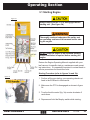
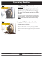
3.1 Starting Engine
figure 3a
Always make sure the PTO is disengaged before
starting unit. (See figure 3b)
Thoroughly read and understand the safety and
pre-operating sections of this manual before staring the engine.
DO NOT start the engine in an enclosed building.
Proper ventilation is required before starting the
engine.
Review the Engine Operating Manual supplied with your
leaf vacuum for specific start-up, maintenance and operating instructions. It is especially important to review break-in
service procedures for brand new units.
Starting Procedure (refer to figures 3a and 3b):
figure 3b
1. Perform all the pre-starting, pre-operating checks outlined in the EOM and in this manual.
2. Make sure the PTO is disengaged as shown in figure
3b.
3. Turn the throttle control (fig. 3a) counter-clockwise 2
revolutions.
4. Depress and hold the Murphy switch while starting.
PTO shown disengaged
ODB COMPANY
800-446-9823
LCT600
28
Operating Section
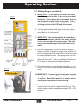
3.1 Starting Engine, continued;
figure 3a
5. IMPORTANT: Do not operate the starter for more
than 30 seconds at a time. To do so may overheat
the starter. If the engine does not start the first time,
wait at least 2 minutes before trying again. If the
engine fails to start after 4 attempts, see the trouble
shooting section of the EOM and this manual.
6. Turn the ignition switch all the way to the right, when
the engine starts release the ignition switch. It should
spring back to the first position.
7. IMPORTANT: If the ignition switch is released before the engine starts, wait until the starter and the
engine stop turning before trying again. This will
prevent possible damage to the starter and/or flywheel.
8. After the engine starts, continue to hold the Murphy
Switch in until the oil pressure gauge reads at least 15
psi. The Murphy shut off switch will not allow the engine
to operate below this level. If the gauge does not rise
above 15 psi withing 5 seconds, stop the engine and
determine the cause. Normal operating oil pressure is
50 psi with oil at normal operating temperature.
9. Check all gauges for normal engine opreration. If operation is not normal, stop the engine and determine the
cause.
figure 3b
10.IMPORTANT: To assure proper lubrication, operate
the engine at or below 1200 rpm with no load for 1
-2 minutes. Extend this period 2 - 4 minutes when
operating at temperatures below freezing.
PTO shown disengaged
ODB COMPANY
11.Watch the coolant temperature gauge. Do not place
engine under load until it is properly warmed up. The
normal engine coolant temperature range is 180 - 202
degrees F.
800-446-9823
LCT600
29
Operating Section
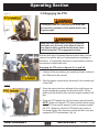
3.2 Engaging the PTO
figure 3b
Thoroughly read and understand the safety and
pre-operating sections of this manual before staring the engine.
PTO shown disengaged
figure 3c
Make sure the intake hose is properly attached
and make sure the front of the hose is clear of
any objects which could be inadvertently vacuumed during the PTO engagement process.
Review the Engine Operating Manual supplied with your leaf
vacuum for specific start-up, maintenance and operating instructions. It is especially important to review break-in service
procedures for brand new units.
Engaging the PTO (refer to figures 3b, 3c and 3d):
1. Perform all the pre-starting, pre-operating checks outlined in
the EOM and in this manual.
safety assist cylinder
figure 3d
2. Start the engine as previously discussed in this manual and
in the EOM.
3. Once the engine has been allowed to thoroughly warm up
(engine temperature gauge should read at least 180 degrees) pull the throttle control until the engine reaches 1000
rpm.
4. Grasp the PTO handle (fig. 3b) and slowly raise the handle.
NOTE: Some units have a PTO assist cylinder which engages the PTO at a specific speed in order to properly engage
the PTO. Because of this the PTO handle only needs to
be raised slightly, then the assist cylinder will take over and
engage the PTO automatically. (fig. 3c)
PTO shown fully engaged
ODB COMPANY
800-446-9823
LCT600
30
Operating Section
3.2 Engaging the PTO, continued;
figure 3d
5. MPORTANT: If the unit experiences any heavy vibrations or makes any unusual noises, shut the engine down and after following the necessary safety
guidelines, have a qualified technician investigage
the cause. DO NOT operate a unit that is in a state of
disrepair.
PTO shown fully engaged
figure 3b
6. If the unit is running smoothly and does not dispaly any
excessive vibration, the unit is ready to vacuum leaves.
NOTE: Please see the next section before vacuuimg
leaves.
Disengaging the PTO (refer to figures 3b and 3d):
1. Decrease the rpm to 1000 rpm.
2. Grasp the PTO handle and slowly disengage the PTO.
3. When the PTO is fully disengaged, the engine can be shut
down.
PTO shown disengaged
ODB COMPANY
800-446-9823
LCT600
31
Operating Section
3.3 Fluid Drive Coupler (if equipped)
Figure 3.3A
Thoroughly read and understand the safety and
pre-operating sections of this manual before staring the engine.
Make sure the intake hose is properly attached
and make sure the front of the hose is clear of
any objects which could be inadvertently vacuumed at any time.
There is no PTO engagement when the unit is equipped
with a Fluid Drive Coupler. The impeller is ALWAYS engaged and rotating.
The suction impeller is ALWAYS rotating when the engine is running
and for a few minutes after the engine is shut off. Exercise caution
whenever the unit is running.
IMPORTANT: If the unit experiences any heavy vibrations or makes any unusual
noises, shut the engine down and after following the necessary safety guidelines,
have a qualified technician investigate the cause. DO NOT operate a unit that is in a
state of disrepair.
ODB COMPANY
800-446-9823
LCT600
32
Operating Section
3.4 Vacuuming Leaves
Thoroughly read and understand the safety, pre-operating and operating sections of this manual before vacuuming. Wear the proper
safety equipment as outlined in this manual.
Make sure the exhaust hose is connected to the box container
properly before vacuuming leaves. Visually inspect the leaves
before vacuuming for any material that could be harmful to the leaf
vacuum or people. This includes bottles, wood, steel, glass, stone
or other hard or breakable objects.
Vacuuming Leaves:
1. Start the engine and engage the PTO using the procedures stated earlier
in this manual.
2. Set the engine throttle to around 1400 rpm.
3. NOTE: Always vacuum leaves using the lowest rpm as possible. This
saves fuel and decreases the amount of dust escaping the box container.
4. Lower the intake hose to a few inches above the leaf pile. Hold the intake
nozzle at a 45 degree angle to allow proper air flow. This should allow
the leaves to be vacuumed. DO NOT bury the intake nozzle into the leaf
pile, this will cut off the air flow and will make vacuuming much more difficult and increase the chance of clogging.
5. If the leaves are not vacuuming, increase the rpm to 1400 and try vacuuming at this setting.
6. NOTE: Wet leaves will need higher rpm’s to vacuum whereas dry leaves
will only need minimal rpm’s.
7. Continue moving the nozzle in a sweeping motion above the leaves while
vacuuming.
ODB COMPANY
800-446-9823
LCT600
33
4.0 MAINTENANCE SECTION
Read and understand this entire manual before operating, maintaining or repairing the leaf vacuum.
4.0 MAINTENANCE SECTION
4.0 MAINTENANCE SECTION
4.1 Maintence Overview:...................................................................................... 35
4.2 Maintenance and Lubrication ........................................................................ 36
4.3 Lubrication:..................................................................................................... 37
4.4 Preventative Maintenance............................................................................... 40
4.5 Torque Values.................................................................................................. 44
ODB COMPANY
800-446-9823
LCT600
34
Maintenance Section
4.1 Maintence Overview:
Only properly trained personnel should perform maintenance or repair on this equipment. Consult ODB before performing any maintenance procedures that is not specificially covered in this manual.
Improper maintenance or repair may void any and all warranties on
this equipment.
Improper maintenance or repair CAN result in equipment damage
and/or personal injuries.
BEFORE CONTINUING, please read and understand the Safety, Preoperating and Operating sections of this manual before doing any
prodcedures in this section.
A properly maintained leaf vacuum will dramatically extend the life of the
unit and will create a safer work place as well. For the general safety and
welfare of all personnel it is important to create a scheduled maintenance
program that covers all the elements in this manual as well as the engine,
PTO and axle owner’s manuals provided with this unit.
Use the chart on the following page as a guide for your scheduled maintenance program. If there are any questions concerning any ot these procedures please call the factory or your dealer.
ODB COMPANY
800-446-9823
LCT600
35
Maintenance Section
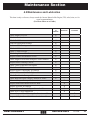
4.2 Maintenance and Lubrication
This chart is only a reference, always consult the Owners Manual of the Engine, PTO, axles, hoist, etc. for
actual recommendations
(Use Hour Meter as a Guide)
ITEM
DAILY/
10
HOURS
Check Engine Oil Level
Check coolant level
Check Fuel Filter
X
X
X
Lubricate Main Shaft Bearings
Lubricate PTO Bearings
Check Air Filter
Check / Clean Pre-Filter
Check Lug Nuts and Tire Pressure
Inspect Radiator and Radiator Screen
X
X
X
X
X
X
Check Engine as described in Engine's Owner Manual
X
Inspect Blower Housing Exterior
Check Trailer Lights and Turn Signals
Check Power Band
Inspect Impeller Thoroughly for Damage
Check All Nuts and Bolts for Tightness
Check Tow Bar for Damage / Wear
Check Bolt Hole where Tongue Connects to Trailer
Clean and Inspect Battery and Connections
Inspect Intake and Exhaust Hoses for Wear
Inspect All Ducts for Damage
Remove Blower Face and Inspect Liners for Wear
Check PTO / Clutch Adjustment
Grease / Inspect Wheeel Bearings for Corrosion or Wear
X
X
X
X
X
X
X
40 HOURS /
WEEKLY
X
X
X
X
X
X
Inspect all Hydraulic and Fuel Lines for Leaks or Wear
ODB COMPANY
80 HOURS /
2 WEEKS
X
800-446-9823
LCT600
36
Maintenance Section
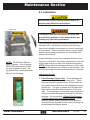
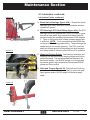
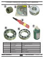
4.3 Lubrication:
Remove the negative battery terminal before attempting any lubrication procedures.
Figure 4.3A
Thoroughly read and understand the safety and
pre-operating sections of this manual before performing any lubrication procedures.
The following are general lubrication procedures for our
standard units. Any special or custom built units may
have other lubrication procedures not directly mentioned
in this manual. Please consult the factory or your dealer
before any lubricating procedures not specifically mentioned in this manual.
NOTE; DO NOT mix different
types of grease. The old grease
MUST BE purged before a different type of grease is used. Mixing grease WILL cause premature
failure to the bearings.
Proper lubrication of your unit correlates directly to how
long your unit will last. A properly maintained unit will last
much longer than a unit that is not maintained properly.
NOTE: Always lubricate bearings at the end of each work
day. This will displace any moisture in the bearings. Also
lubricate thorougly before extended shutdown or storage.
Lubrication Points:
1. Drive Bearings (figure 4.3a): These bearings are
critical components of the belt-driven units. These
bearings should be greased every 10 hours with approximately two strokes from the average hand pump
grease gun. The type of grease used in these bearings are also critical to the performance of the bearings. A multi-purpose, heavy-load, high-temperature,
moisture resistant #2 grease is required for the drive
bearings. We recommend L Mantek Elite Supreme
#1 WG Extreme Duty multi-purpose grease. Other
premium quality grease that matches the above requirements may be used but after years of testing we
recommends the Mantek grease.
ODB COMPANY
800-446-9823
LCT600
37
Maintenance Section
4.3 Lubrcation, continued;
Lubrication Points, continued;
Figure 4.3b
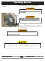
2. Trailer Wheel Bearings (figure 4.3b): Most of the units
are equipped with "EZ-Lube" grease fittings. This allows the
operator to grease the bearings without removing the hubs.
The "EZ-Lube" feature consists of axle spindles that have
been specially drilled and fitted with a grease zerk in their
ends (fig. 4.3c). When grease is pumped into the zerk, it is
channelled to the inner bearing and then flows back to the
outer bearing and eventually back out the grease cap hole.
The trailer wheel bearings should be checked and greased
after the first 30 days of service then at the beginning of
every season.
Grease specifications:
Grease fitting is behind rubber plug
Figure 4.3c
Thickener Point............................Lithium Complex
Dropping Point......................230 degr. C minimum
Consistency............................................NLGI No.2
Additives.........................EP,Corrosion & Oxidation Inhibitors
Base Oil...................Solvent refined Petroleum Oil
Base Oil Viscosity............@40 deg. C 150cSt Min.
Viscosity Index.....................................80 Minimum
Pour Point...................................-10 deg. Minimum
Approved Sources:
Mobil Oil........................................Mobilgrease HP
Exxon/Standard......................................Ronex MP
Kendall Refining...............................Kendall L-427
Ashland Oil Co........Valvoline Val-plex EP Grease.
Penzoil.......Premium Wheel Bearing Grease 707L
For any questions concerning wheel lubrication please consult
the axle owner's manual supplied with your leaf collector or
contact the manufacturer or dealer.
ODB COMPANY
800-446-9823
LCT600
38
Maintenance Section
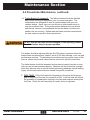
4.3 Lubrication, continued;
Figure 4.3d
Lubrication Points, continued;
3. Boom Swivel Bearings (figure 4.3d): Grease the boom
bearings once every week with a multi-purpose moisture
resistant #2 grease.
One fitting on each bearing
Figure 4.3e
4. PTO Bearing & PTO Shaft Fitting (figure 4.3e):The PTO
bearings should be greased after every 50 hours of operation with a high grade, high temperature lithium base #2
lubricant having an operating temperature of 200 degrees
F. Three to five pumps with a hand operated grease gun
is sufficient. NOTE: Units manufactured after 2000 may
not have a PTO bearing grease fitting. These bearings are
sealed and do not require greasing. The PTO crossover
shaft and linkage should be lubricated with high temperature lithium base #2 lubricant after 200 hours of operation.
5. Hinge and Friction Points: Leaf vacuum operation and
longevity can be improved by keeping hinges and friction
points lubricated. It is recommended that lubricaton be
performed weekly. Use SAE30 weight oil on hinges and
a premium grade, high temperature lithium based EP#2
grease on friction points.
6. Hitch and Tongue (figure 4.3f): The hitch and hitch ring
should be checked and lubricated daily to minimize wear.
Apply grease and/or SAE30 weight oil wherever applicable.
Figure 4.3f
ODB COMPANY
800-446-9823
LCT600
39
Maintenance Section
4.4 Preventative Maintenance
Remove the negative battery terminal before attempting any maintenance procedures.
Thoroughly read and understand the safety and pre-operating sections of this manual before performing any maintenance procedures.
The following are general preventative maintenance procedures for our standard units. Any special or custom built units may have other preventative
maintenance procedures not directly mentioned in this manual. Please consult
the manufacturer before doing any preventative maintenance procedures not
specifically mentioned in this manual.
Proper preventative maintenance of your unit, just like lubrication, correlates
directly to how long your unit will last. A properly maintained unit will last much
longer than a unit that is not maintained properly.
Preventative Maintenance:
1. Engine Oil: Change the oil and oil filter according to schedules provided
in your engine's owner's manual (EOM). The engine oil level should be
checked every day. The level should be checked after the engine has
been stopped for a period of time. This will allow the oil to drain back into
the oil pan, allowing a better indication of the true oil level. If the level is
low, see the engines owner's manual for the correct type of oil.
2. Engine Coolant: Check the coolant level before starting the unit each day.
The coolant level should not be less than one inch below the top of the
radiator.
NEVER check the engine coolant when the engine is hot. Allow the
engine to cool at least one hour before checking the coolant. Check
the engine owner's manual for instructions. ALWAYS wear eye and
hand protection when working with the radiator.
ODB COMPANY
800-446-9823
LCT600
40
Maintenance Section
4.4 Preventative Maintenance, continued;
3. Engine Radiator: The engine radiator on a leaf vacuum becomes
clogged with dust and debris frequently because of the nature of the job.
If the radiator is not cleaned properly it WILL cause improper cooling and
WILL eventually cause serious damage to your engine. The debris accumulating on the radiator can be lessened by lowering the RPM on the engine to a level just enough to vacuum the leaves. The higher the RPM the
more dust that is put into the air. Also, it may be necessary to put mesh or
tarps on the top of the leaf box container to reduce the debris and dust. If
this is done, make sure there is enough air ventilation on the box so the
box is not blown apart. Proper belt condition and coolant mix-ratio, as
well as coolant conditioners, are all critical to proper engine cooling. See
NEVER attempt to clean or inspect the radiator with the engine running or while the engine is HOT. Allow the engine to cool at least
one hour before mantaining the radiator. Check the engine owner's
manual for instructions. ALWAYS wear eye and hand protection
when working with the radiator.
the engines owner's manual for specifics on coolant mixture ratios and conditioners. The radiator should be inspected and cleaned with compressed
air everyday at the very least.
4. Engine Air Cleaner: Due to the large amounts of dust generated in collection leaves, it is critical to your engine's life that the pre-cleaner and air filter
be maintained properly. The pre-cleaner should be cleaned at least daily of
any debris that has accumulated. If conditions warrant it should be cleaned
more. The air filter should be checked daily and should be replaced at the
first sign of it being dirty. DO NOT attempt to clean the air filter, replace the
dirty air filter. It is a good idea to clean out the air filter housing once a week
to clean any dust debris that may have accumulated
5. Tires and Wheels: Tires and wheel lug nuts should be checked on a daily
basis. Tires should be checked for excessive wear and proper air pressure.
Check the side wall of the tire for proper inflation pressure. Torque all 1/2"
diameter lug nuts from 90 to 120 foot pounds. Torque all 5/8" diameter lug
nuts from 175 to 225 foot pounds. Consult the axle manufacturers owner's
manual for more detailed information.
ODB COMPANY
800-446-9823
LCT600
41
Maintenance Section
4.4 Preventative Maintenance, continued;
6. Trailer Brakes (if equipped): The trailer's brakes should be checked
daily, before leaving the equipment yard, for proper operation. The
trailer brakes are designed to work in synchronization with your tow
vehicles brakes. Never use your tow vehicle or trailer brakes alone to
stop the combined load. The synchronization between the tow vehicle
and the leaf vacuum is accomplished through the brake controller and
needs to be set correctly. Please read the brake controllers manual and
the axle owner's manual for these procedures.
DO NOT tow the leaf vacuum with damaged or non-operating brakes.
Check the brakes daily for proper operation.
The brakes should be adjusted after the first 200 miles of operation when the
brake shoes and drums have "seated" and at 3,000 mile intervals, or as use and
performance requires. The adjustment procedures are beyond the scope of this
manual, please see the axle owners/service manual for specific instructions.
The trailer brakes should be inspected and serviced at yearly intervals or more
often as use and performance requires. Magnets and shoes must be changed
when they become worn or scored thereby preventing adequate vehicle braking.
Again, see the axle owner's/service manual for specific procedures.
7. FUEL TANK: Fill the fuel tank at the beginning of the work shift leaving a
gap of at the top of the tank for expansion of fuel. A full fuel tank will reduce
the possibility of condensation forming in the tank and moisture entering the
fuel lines. Check the fuel lines daily for cracks, holes or tightness.
ODB COMPANY
800-446-9823
LCT600
42
Maintenance Section
4.4 Preventative Maintenance, continued;
Preventative Maintenance, continued;
ALWAYS wear eye and hand protection when working with the battery.
8. BATTERY: The units are supplied with "maintenance free" batteries so
there is no need to check fluid levels but the battery terminals should be
checked daily for corrosion. Remove any corrosion with a wire brush and
coat the terminals with light grease or petroleum jelly to reduce the possibility of corrosion. Also check the battery cable for wear all cable connections
and battery tie downs to be certain that they are not loose.
Remove the negative battery cable before opening the belt guard.
9. DRIVE BELT (if equipped): The main drive belt should be checked daily for
cracks and for proper tension. If the belt shows any sign of cracking it should
be replaced immediately. The proper tension of the belt should be approximately 1/2" deflection when applying a 8 pound pull.
10.FASTENERS: Fasteners should be checked weekly for the first 30 days and
monthly thereafter. They must be in place at all times and properly torqued.
For general torque values see the torque chart at the end of this section.
11.INSTRUMENT PANEL AND CIRCUIT BOARD: The instrument panel and
circuit board should be cleaned with compressed air daily. Also the circuit
board connectors should be wiped clean and have nonconductive grease applied weekly to help maintain solid connections.
12.BOOM HYDRAULIC PUMP: Check the fluid level daily. If fluid needs to be
added, automatic transmission fluid (ATF) is recommended. Clean debris and
oil off the solenoid and pump daily. A build up of debris can cause premature
failure to the pump. Check and tighten all hydraulic fittings making sure there
are no leaks.
ODB COMPANY
800-446-9823
LCT600
43
Maintenance Section
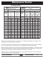
4.5 Torque Values
INCH BOLT AND CAP SCREW
TORQUE VALUES
TYPE
SAE GRADE
5
8
HEAD
MARK
METRIC BOLT AND CAP SCREW TORQUE
VALUES
CLASS
8.8 or 9.8
10.9
12.9
HEAD
MARK
SIZE(D)
SIZE(D)
LB-FT
LB-FT
1/4"
5/16"
3/8"
Lub*
7
15
26
Dry*
9
18
33
Lub*
10
21
36
Dry*
12.5
26
46
7/16"
1/2"
9/16"
5/8"
3/4"
7/8"
41
63
90
125
225
360
52
80
115
160
280
450
58
90
130
175
310
500
1"
540
675
1-1/8"
675
1-1/4"
LB-FT
LB-FT
LB-FT
M6
M8
M10
Lub*
6.5
16
32
Dry*
8.5
20
40
Lub*
9.5
24
47
Dry*
12
30
60
Lub*
11.5
28
55
Dry*
14.5
35
70
75
115
160
225
400
650
M12
M14
M16
M18
M20
M22
55
88
140
195
275
375
70
110
175
250
350
475
80
130
200
275
400
540
105
165
255
350
500
675
95
150
240
325
460
625
120
190
300
410
580
800
750
975
M24
475
600
675
850
800
1000
850
1075
1350
M27
700
875
1000 1250 1150 1500
950
1200
1500
1950
M30
950
1200 1350 1700 1600 2000
1-3/8"
1250
1550
2000
2550
M33
1300 1650 1850 2350 2150 2750
1-1/2"
1650
2100
2650
3350
M36
1650 2100 2350 3000 2750 3500
*Lub means coated with a lubricant such as engine oil, or fasteners with phospate or oil coatings. "Dry"
means plain or zinc plated without any lubrication.
DO NOT use these values if a different torque value or tightening procedure is given for a specific application. Torque values listed are for general use only. Check tightness of fasteners periodically.
Make sure fastener threads are clean and that you properly start thread engagement. This will prevent them
from failing when tightening. Fasteners should be replaced with the same or higher grade. If higher grade
fasteners are used, these should only be tightened to the strength of the original.
Tighten plastic insert or crimped steel-type lock nuts to approximately 50 percent of the dry torque shown
inthe chart, applied to the nut, not the bolt head.
ODB COMPANY
800-446-9823
LCT600
44
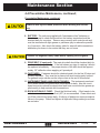
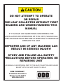
DO NOT ATTEMPT TO OPERATE
OR REPAIR
THE LEAF COLLECTOR WITHOUT FIRST
READING AND UNDERSTANDING THIS
MANUAL
IF YOU HAVE ANY QUESTIONS CONCERNING THE
INSTALLATION OR OPERATION OF THIS UNIT, PLEASE CALL
ODB FOR ASSISTANCE BEFORE ATTEMPTING TO REPAIR OR
OPERATE THE UNIT.
IMPROPER USE OF ANY MACHINE CAN
RESULT IN SERIOUS INJURY!
STUDY AND FOLLOW ALL SAFETY
PRECAUTIONS BEFORE OPERATING OR
REPAIRING UNIT
THIS MANUAL IS AN INTEGRAL PART OF THE LEAF COLLECTOR AND SHOULD
BE KEPT WITH THE UNIT WHEN IT IS SOLD.
ODB COMPANY
5118 Glen Alden Drive
Richmond, VA 23231
800-446-9823
5.0 SERVICE SECTION
Service and Troubleshooting
Wiring Diagrams
ODB COMPANY
5118 Glen Alden Drive
Richmond, VA 23231
800-446-9823
SERVICE SECTION
THE
SERVICE AND TROUBLESHOOTING
5.0 SERVICE SECTION
5.1 Engine Electrical Troubleshooting Guide............................................................... 48
5.2 Auto Mfg. Clutch Adjustment - 2008 and after...................................................... 49
5.3 Hydraulic Boom Troubleshooting Guide................................................................ 50
5.4 Impeller Installation and Removal.......................................................................... 51
5.4 Impeller Installation and Removal, continued........................................................ 52
5.5 Belt Adjustment and Replacement Guide............................................................... 53
5.6 Flange Bearing Installation and Removal............................................................... 54
5.6 Flange Bearing Installation and Removal............................................................... 55
5.7 Replacing the Blower Housing Liners.................................................................... 56
5.7 Replacing the Blower Housing Liners; continued,................................................. 57
ODB COMPANY
5118 Glen Alden Drive
Richmond, VA 23231
800-446-9823
SERVICE AND TROUBLE SHOOTING
THE
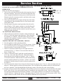
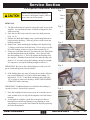
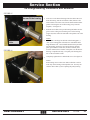
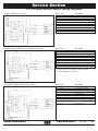
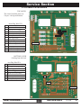
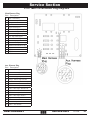
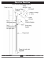
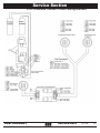
Service Section 5.1 Engine Electrical Troubleshooting Guide
ENGINE RUNS ONLY WHEN OVERRIDE BUTTON IS
DEPRESSED
Make sure the PTO is disengaged.
1. Take a look at the limit switch located at the inspection door of
the blower housing. Check to be sure that the inspection door
closes completely and that the door presses in the limit switch.
The limit switch is extremely sensitive and only needs to open
1/64” to shut the engine off.
2. If the inspection door closes properly and presses in the limit
switch properly, then disconnect the two wires from the back
of the limit switch.
3. Start the engine using the normal procedure then release the
shut off button. If the engines continues to run then the problem lies in the limit switch or the limit switch wiring. If the
engine still cuts off then the limit switch is not the cause, go to
Testing the shut off switch.
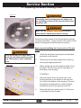
TO TEST THE LIMIT SWITCH:
4. With an ohm meter check the resistance of the terminals A &
B (Fig. 1) while the button is not depressed. There should be
no resistance or continuity. With the button depressed there
should be full continuity or infinite resistance, if not the switch
is bad and should be replaced.
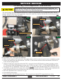
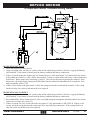
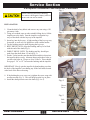
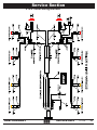
TESTING THE SHUT OFF (MURPHY) SWITCH:
5. Turn the ignition switch to the first position.
6. Put a test light to terminal B (Fig. 3) to test for current. If there
is no current at B, power is not getting to the shut off switch.
Then the problem is not the shut off switch.
7. If there is current at terminal B, put a test light on the fuse
at location Z (Fig. 3). If there is no current there the fuse is
blown. Replace fuse.
8. If there is current at B and Z, push the override button (letter X, Fig. 3) in on the shut off switch. While the button is
depressed place the test light on terminal C (Fig. 3). If there
is current at terminal C then the shut off switch is functioning
properly and the problem lies elsewhere. If there is no current
at terminal C then the shut off switch is defective and needs to
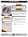
be replaced.
9. Next locate the fuel solenoid valve located on the fuel injector pump (Letter C, Fig. 2). It has an orange wire running to it. Pull the ignition switch to the first position. Put a test light on the terminal of the fuel solenoid where
the wire is attached. Test light should light up showing current, if not shut off switch is bad. Replace.
10.If engine still cuts off after shut off button is released then test the water temperature switch (located on the engine
block, Letter D, fig. 2) by removing the brown wire attached to the temperature switch. Start the engine using
the normal procedure then release the shut off button. If the engine continues to run then the water temperature
switch is defective. Replace the switch. If the engine shuts off, do the same test on the oil pressure switch. If the
engine continues to shut off after this test call ODB for additional service procedures.
ODB COMPANY
800-446-9823
LCT600
48
Service Section 5.2 Auto Mfg. Clutch Adjustment - 2008 and after
Rotating Shafts, pulleys, and moving belts can cause severe injury or can be fatal. The
engine and driven unit MUST be completely stopped before any adjustments or work is attemped to the engine, driven unit, or the PTO clutch itself.
The clutch linkage should be checked after the first 15 hours of operation and every 40 hours there after. An improperly adjusted clutch can result in premature wear to the clutch disc, flywheel and the throwout bearing and will
void the warranty on the clutch and PTO.
PIC# 2
PIC# 1
Rocker Ball
Adjusting Nut
Return Spring (remove)
PIC# 4
PIC# 3
1/8" GAP
1/8" GAP
Gauge Tool
ADJUSTMENT OF THE CLUTCH LINKAGE
1. Make sure the engine is OFF and remove the negative battery cable to ensure the unit can not accidently be started.
2. Remove the spring from the throwout arm. (See PIC# 1) An accurate measure of the arm tension CAN NOT be
made with the spring attached.
3. With the clutch in the engaged position (the PTO is engaged when the PTO handle is pointing straight up on the
LCT600 and LCT6000 and pointing out to the side (3 o'clock) on the LCT60C, LCT650 and SCL800TM) adjust
the nut (See PIC# 2) against the "rocker ball" until a 1/8" gap between the nut and rocker ball is visible (See PIC# 3).
4. If available, use the special 1/8" gauge tool to slip between the nut and rocker ball. With the proper adjustment the
gauge should slide between the nut and rocker ball with a slight amount of pressure. (See PIC# 4)
5. Move the adjustment nut to create the 1/8" gap.
6. Re-install the return spring.
7. Place the handle in the disengaged position. Check to make sure that the PTO output shaft turns freely.
ODB COMPANY
800-446-9823
LCT600
49
Service Section 5.3 Hydraulic Boom Troubleshooting Guide
BOOM WILL NOT GO UP
1. Check the fluid level in the reservoir.
2. Using a test light make sure there is current at the outside solenoid post (item#2), this has a 4 gauge Red battery
cable attached. If no current is found check the battery condition and battery connections.
3. If there is current at this post, depress the "up" button (item# 3), while pressing the "up" button check for current
at the middle post (item# 1), it has a White wire attached. If there is current at the post (item# 1) the solenoid may
be defective. Run a jumper wire connecting #1 and #2. This will test the motor, bypassing the solenoid. If the
boom raises, the motor is okay (motor part# MP-08004) but the solenoid is bad and needs to be replaced. Solenoid part number is MP-17744.
4. If there is NO current at the post (item# 1) check the wiring between the switch and the solenoid. If the wiring
checks out okay, the switch is bad and needs to be replaced.
BOOM WILL NOT GO DOWN
1. Using a test light make sure there is current at the outside solenoid post (item#2), this has a 4 gauge Red battery
cable attached. If no current is found check the battery condition and battery connections.
2. Press and hold the "down" button (item# 4), take a test light and probe through the insulation and test for current
on the red wire at the valve (item #5).
3. If there is current, the valve is bad and need to be replaced. Valve part number is MP-19283.D. If there is NO
current, check the wiring between the switch and valve, especially any connections. If the wiring checks out
okay, the switch is bad and needs to be replaced.
ODB COMPANY
800-446-9823
LCT600
50
Service Section 5.4 Impeller Installation and Removal
Fig. 1
Before removing the blower housing
face remove the negative battery cable to
ensure unit can not be started.
Direct
Drive
REMOVAL
1. The blower housing face must be removed to gain access to the
impeller. Use an overhead crane or forklift to support the face
while removing.
2. Once the face has been removed, remove the shaft protector
(Fig. 1 or 2).
3. Saturate the shaft and bushing using a penetrating lubricant to
help loosen the bushing. Clean any grease or debris from the
bushing and shaft.
4. Remove the 3 bolts attaching the bushing to the impeller.(Fig.
3) Being careful not to break the bolts. If a set screw is on the
lip of the bushing, loosen it using an allen wrench.(Fig. 4)
5. Using two of the bolts that were just removed screw those bolts
into the threaded holes on the bushing. Drive the two bolts
into the bushing.(Fig. 5) This will separate the bushing from
the impeller. Alternate from one bolt to the other driving only
about a 1/4” at a time to keep the bushing coming out straight.
It is imperative to keep the bushing straight to remove it.
IMPORTANT: Be sure to drive the bushing out evenly or it will
get in a bind making removal much harder.
Fig. 2
Belt
Drive
Fig. 3
Fig. 4
6. If the bushing does not come off using the two bolts, drill and
tap several additional 3/8-16 holes around the bushing. Using Grade 8, 3/8-16 - 2 inch bolts, alternately drive the bolts
1/4” at a time to remove the bushing. KEEP THE BUSHING
STRAIGHT while removing.
IMPORTANT: If additional holes were drilled in the bushing, it
can not be reused. It must be be replaced.
Fig. 5
7. Once the bushing has been removed use an overhead crane or
other suitable device to help lift the impeller out of the blower
housing.
8. At this point it would be a good idea to inspect the blower
housing liners and blower housing for any damage or wear.
Any damage or wear to the liners should be fixed by replacing
the liners immediately.
ODB COMPANY
800-446-9823
LCT600
51
Service Section 5.4 Impeller Installation and Removal, continued
Fig. 1
Before removing the blower housing
face remove the negative battery cable to
ensure unit can not be started.
INSTALLATION
1. Clean the shaft of any debris and remove any rust using a 120
grit emory cloth.
2. Using an overhead crane or other suitable lifting device lift the
impeller on to the shaft. Turn the impeller to align the keyways of the shaft with the keyway in the impeller.
3. Insert key into the keyway. A light sanding of the keyway may
be needed, as well as a few light blows with a rubber mallet.
4. Tap the bushing onto the shaft aligning the keyways.
5. BELT DRIVE UNITS: Align the bushing and key to be flush
with the end of the shaft (Fig 1).
6. DIRECT DRIVE UNITS: The bushing and key should protrude from the shaft about 1/2 inch (Fig. 2).
7. Put the 3 bolts into the non-threaded holes and drive them into
the impeller holes evenly. Alternate between the three bolts as
you drive the bolts in. Torque to 40 to 50 lbs/ft. There should
be a gap of 3/8” to 1/2” between the bushing and the impeller.
Fig. 2
Fig. 3
IMPORTANT: Slowly spin the impeller by hand making sure that
the back of the impeller is not hitting any of the bolt heads located
at the back of the blower housing.
8. If the bushing has a set screw on it, tighten the screw snug with
an allen wrench (Fig. 3). This will help keep the key in place.
9. Install the shaft protector on to the shaft (Fig. 4 or 5).
Fig. 4
Direct
Drive
Fig. 5
Belt
Drive
ODB COMPANY
800-446-9823
LCT600
52
Service Section 5.5 Belt Adjustment and Replacement Guide
Before opening the belt cover emove the negative battery cable to ensure unit can not be started.
Figure #1
Belt Removal
1. Make sure the leaf vacuum is not running and remove the battery cable from
the negative battery terminal to ensure that the unit cannot be accidentally
started.
2. Open the belt guard assembly to gain access to the belt and pulleys.
3. Loosen the four motor mount bolts (Items A and B, figures #1 and #2) located
above the motor mount adjustment brackets.
4. To create slack in the belt, the motor assembly needs to be moved toward the
blower housing. Locate the adjustable motor mount nuts (C) at the rear of the
unit (figure #3). Use a 7/8” socket to turn the nuts counter-clockwise alternating between the left and right mounts. Move one side approximately two
inches then move the other side to keep the mounts from binding.
5. Continue moving the motor inward until the belt is loose enough to be removed.
Belt Replacement
1. Place the belt around the two pulleys, aligning the grooves of the belt with the
grooves of the pulley.
2. The motor assembly needs to be moved back away from the blower housing
to tighten the belt. Using the adjustable motor mount nuts at the rear of the
unit (Item C, figure #3) turn one of the nuts clockwise to start moving the motor assembly. Move the motor assembly approximately two inches then do the
same to the other side. Continue alternating between the two sides until the
belt is tight.
3. IMPORTANT: Use a straight edge to make sure the pulleys are aligned (figure
#4).
4. If the pulleys are not aligned use either of the adjustable motor mount nuts to
compensate for the mis-alignments. Check the tightness at the center of the
belt between the two pulleys. The belt should depress approximately 1/2”.
5. Tighten down the 2 bolts closest to the blower housing (Item A, figures #1 and
#2). Loosen the adjustable motor mount nuts (Item C, figure #3) by turning
counter-clockwise a couple of turns until the front 2 motor mount bolts (Item
B, figures #1 and #2) are competely straight. The motor assembly should not
move, if it does move then the bolts (Item A) were not tight enough and the
belt would need to be readjusted using the steps above. Once the bolts (Item
B) are straight tighten them down.
6. Close the belt guard assembly and secure it with the latches.
7. Re-attach the battery cable to the negative battery post.
8. Start the engine and increase the throttle to 750 RPM’s.
9. Engage the clutch, listening for any squealing from the belt. If the belt
squeals use the above directions to tighten the belt a little more.
10.After approximately 8 hours of use the new belt should be checked for proper
tightness in case the belt stretched.
ODB COMPANY
800-446-9823
A
B
B
Figure #2
A
Figure #3
C
Figure #4
LCT600
53
Service Section FIGURE #1
Pulley Bearing
5.6 Flange Bearing Installation and Removal
Impeller Bearing 1. Place the bearings on to the black bearing plates inside the
pedistal. Hand tighten the bolts onto the nuts at this point.
Concentric Collars
Grooved side should face the
bearing
Slide Shaft this way
FIGURE #2
Shaft
Bearing Plate
2.
Slide the shaft through the back of the impeller bearing and
half way to the pulley bearing. The shaft should fit tight.
Clean the shaft and remove any burrs if necessary. Also
lightly polishing it with a fine emery may ease installation.
3.
Before going through the pulley bearing, place both concentric collars (black collars) onto the shaft (figure #1). Make
sure the grooved side is facing the bearing.
4.
Continue sliding the shaft through the pulley bearing until the
shaft protrudes out from the pulley side 5-5/8". (Figure #2)
5.
Now slide the concentric collar toward the respective bearing
making sure the grooved side is toward the bearing.
6.
Turn the concentric collar clockwise until it slips over the
inner ring extension and engages the eccentric. Turn by hand
until the parts are locket together.
7.
Place a punch or drift in the blind hole in the collar and strike
it sharply to lock the collar and ring tightly together (figure
#3)
8.
Tighten the set screws with an Allen wrench until the set
screw stops turning and the Allen wrench starts to spring.
(Figure #4)
9.
Completely tighten all four of the nuts to secure each bearing.
Continued...
FIGURE #3
ODB COMPANY
FIGURE #4
800-446-9823
LCT600
54
Service Section 5.6 Flange Bearing Installation and Removal
FIGURE #5
RubberGasket
gasketfaces
faces
Rubber
the
rear
of
the
bearing
the rear of the bearing
Grooved side should face the
bearing
Steel Debris
Collar
1.
Now move to the blower housing where the shaft comes out
from the bearing. Put the steel debris collar (chrome color
with a rubber seal on one side) onto the shaft with the rubber
gasket side facing the rear of the bearing (away from the
impeller). See Figure #5.
2.
Push the steel collar seal up to the bearing and make sure the
groove in the collar goes inside the groove in the bearing.
(Figure #6) This creates the sealed fit to keep debris out of the
bearing.
3.
FIGURE #6
4.
NOTE:
If the collar is too large for the hole in the bearing plate, a
"new style" bearing plate will need to be ordered that has a
larger diameter hole. Units manufactured before April 2002
will most likely need to be converted to the new bearing
plate (part number LCT600.603 {all but LCT6000} and
LCT630.104A for the LCT6000. This plate is for the blower
housing or impeller side only. The pulley side bearing does
not use the steel debris collar.
Completely tighten the two Allen head screws. See figure #6.
NOTE:
Each bearing comes with a steel debris collar but it will be
used only on the bearing on the impeller side. You may discard the other collar if you're replacing the pulley bearing.
ODB COMPANY
800-446-9823
LCT600
55
Service Section 5.7 Replacing the Blower Housing Liners
figure 5.5a
Thoroughly read and understand the safety and
pre-operating sections of this manual before working on the unit.
Make sure the negative battery cable is disconnected before opening the blower housing.
Review the safety section of this manual before attempting these procedures. To gain access to the interior of the
blower housing please see the previous sections.
figure 3c
Removing and installing the Liners (refer to 5.5a and
5.5b):
Keep all fuel and fuel fumes away
from the unit when grinding or welding. Work only in a well ventialted
area.
figure 5.5b
1.
Unbolt the the blower housing face as described
previously in this manual.
2.
Remove the curved and straight bolt-in liners by
removing the appropriate bolts.
3.
With a grinder cut out the remaining welds to free
the liners. DO NOT remove the "stop piece" at
the bottom of the housing.
TO INSTALL:
Lip
Weld
Overlap
Piece
Weld
Stop
Piece
Weld
ODB COMPANY
1.
Place the short liner into lip at the rear of the
housing and line up the bottom of the liner with
the "stop" at the bottom of the housing. The short
liner has the overlap piece on it and should be
installed as shown in the pictures at the left.
2.
Tack weld the liner in place every 8 to 10 inches
to help keep the liner in place.
800-446-9823
LCT600
56
Service Section 5.7 Replacing the Blower Housing Liners; continued,
figure 5.5a
Thoroughly read and understand the safety and
pre-operating sections of this manual before working on the unit.
Make sure the negative battery cable is disconnected before opening the blower housing.
Review the safety section of this manual before attempting these procedures. To gain access to the interior of the
blower housing please see the previous sections.
figure 3c
Installing the Liners (refer to 5.5a and 5.5b), continued;
Keep all fuel and fuel fumes away
from the unit when grinding or welding. Work only in a well ventialted
area.
figure 5.5b
Lip
Install the long liner the same way as the short
liner except the long liner should slip under the
overlap piece. Make sure the liner slips under the
rear lip and the overlap piece.
4.
Tack weld the long liner to the overlap piece and
tack weld around the liner as you did on the short
liner.
5.
Install the two bolt-in liners just as they were
removed.
Weld
Overlap
Piece
Weld
3.
Stop
Piece
Weld
ODB COMPANY
800-446-9823
LCT600
57
5.10 WIRING DIAGRAMS
5.10 WIRING DIAGRAMS
5.10.1 Engine Wiring Diagram.............................................................................. 59
5.10.2 Engine Main Harness - Enlarged................................................................ 60
5.10.3 Auxillary Engine Harness - Enlarged......................................................... 61
5.10.4 Engine Wiring Harness Descriptions.......................................................... 62
5.10.4 Engine Wiring Harness Descriptions, continued........................................ 63
5.10.5 Engine Rocker Switch Wiring Diagrams.................................................... 64
5.10.6 Main Circuit Board..................................................................................... 65
5.10.7 Main Circuit Board Plug Diagrams............................................................ 66
5.10.8 Trailer Plug Wiring Diagram...................................................................... 67
5.10.9 Trailer Wiring Harness ............................................................................... 68
5.10.10 Brake Wiring Harness .............................................................................. 69
5.10.11 Boom Wiring Diagram.............................................................................. 70
5.10.12 Remote Throttle / Clutch Wiring Harness ............................................... 71
ODB COMPANY
5118 Glen Alden Drive
Richmond, VA 23231
800-446-9823
WIRING DIAGRAMS
WIRING DIAGRAMS
Service Section Engine Main Harness
Engine Wiring Harness Diagram
June 2005 and after
1
Note:
2
Aux Engine Harness
The number in parentheses is the pin
number the wire goes to. If there are two
numbers the first number is the pin for the
main harness, while the second number is
the pin number of the smaller harness
59
LCT600
800-446-9823
ODB COMPANY
Please see enlarged diagrams on the following
pages:
5.10.1 Engine Wiring Diagram
Service Section 5.10.2 Engine Main Harness - Enlarged
Engine Main Harness
ODB COMPANY
800-446-9823
LCT600
60
Service Section 5.10.3 Auxillary Engine Harness - Enlarged
Aux Engine Harness
Note:
Not all wires will be installed in the small
harnesses. If the unit wasn’t ordered with the
factory installed option then the wiring to that
option may not be included in the harness
ODB COMPANY
800-446-9823
LCT600
61
Service Section 5.10.4 Engine Wiring Harness Descriptions
ENGINE MAIN HARNESS
PIN #
COLOR
DESCRIPTION
1
2
3
4
5
6
7
8
9
10
11
12
13
"+" from Solenoid (battery)
Starter Solenoid
Fuel Shutoff Solenoid
"-" from Solenoid (battery)
Alternator Energize "+"
Oil Sender
Tach Signal from Alternator
Emergency Stop Button (650 only) goes to Limit Switch plug pin #5
Inspection Door on Blower Housing, goes to Limit Switch plug pin #3
Fuel Sender, goes to Limit Switch Plug pin #5
Water Temperature Sender on Engine Block
Water Temperature Switch on Engine Block
Oil Pressure Switch on Engine Block
Red
Red w/ Blue Stripe
Orange
Black
Purple
White w/ Red Stripe
White
Tan w/ Black Stripe
Tan
Pink
Blue
Blue w/ Black Stripe
Red w/ Black Stripe
AUXILLARY ENGINE HARNESS
1
2
3
4
5
6
7
8
9
10
11
12
13
14
15
16
Red 10 Gauge
Yellow
Yellow
"+" from Solenoid (Battery)
Aux "+" from Ignition; goes to Aux Plug Harness pin #5
Aux "+" from Ignition; goes to Remote Clutch Harness pin #5
Yellow w/ Green Stripe
[empty]
Green w/ Yellow Stripe
Yellow w/ Blue Stripe
[empty]
Blue w/ Yellow Stripe
Yellow w/ Purple Stripe
Purple w/ Yellow Stripe
Yellow
Black 10 gauge
Yellow
Clutch Engage; goes to Remote Clutch Harness pin #3
Clutch Disengage; goes to Remote Clutch Harness pin #4
Throttle Fast; goes to Remote Clutch Harness pin #7
Throttle Slow; goes to Remote Clutch Harness pin #8
Strobe Light "+"; goes to Strobe Light Harness pin #1
Strobe Light Aux; goes to Strobe Light Harness pin #3
Aux "+" from Ignition; goes to Aux Plug Harness pin #1
"-" from Solenoid (Battery)
Aux "+" from Ignition; goes to Aux Plug Harness pin #3
STROBE LIGHT HARNESS
Yellow w/ Purple Stripe
Black
Purple w/ Yellow Stripe
Black
Fuel Sender "+"; came from Engine Main Harness pin #10
Strobe Light "-"; came from ground to solenoid
Strobe Switch Aux "+"; came from Aux Engine Harness pin #13
Strobe Switch Aux "-"; came from ground on Solenoid
Continued ... -->
ODB COMPANY
800-446-9823
LCT600
62
Service Section 5.10.4 Engine Wiring Harness Descriptions, continued
FUEL & LIMIT SWITCH HARNESS
Pink
Fuel Sender "+"; came from Engine Main Harness pin #10
Black
Fuel Sender "-"; came from ground to solenoid
Tan
Inspection Door "+"; came from Engine Main Harness pin #9
Black
Inspection Door "-"; came from ground to solenoid
Tan w/ Black Stripe
Emergency Stop Button "NO"; came from Engine Main Harness #8
Black
Emergency Stop Button "COM"; came from ground on Solenoid
[empty]
REMOTE THROTTLE AND CLUTCH HARNESS
1
Yellow
"+" from Ignition; came from Aux Engine Harness pin# 3
2
Black
"-" from Ignition; came from ground on Solenoid
3
Yellow w/ Green Stripe
Clutch Engage; came from Aux Engine Harness pin# 6
4
Green w/ Yellow Stripe
Clutch Disengage; came from Aux Engine Harness pin# 4
5
[empty]
6
[empty]
7
Yellow w/ Blue Stripe
Throttle Fast; came from Aux Engine Harness pin# 9
8
Blue w/ Yellow Stripe
Throttle Slow; came from Aux Engine Harness pin# 11
9
[empty]
AUX PLUG IN HARNESS
1
Yellow
"+" from Ignition; came from Aux Engine Harness pin# 14
2
Black
"-" from Ignition; came from ground on Solenoid
3
Yellow
"+" from Ignition; came from Aux Engine Harness pin# 16
4
Black
"-" from Ignition; came from ground on Solenoid
5
Yellow
"+" from ignition; came form Aux Engine Harness pin# 2
6
Black
"-" from ignition; came from ground on solenoid
7
[empty]
8
Orange w/ Yellow Stripe
Rocker Switch; came from Aux Engine Harness pin# 5
9
Yellow w/ Orange Stripe
Rocker Switch; came from Aux Engine Harness
ODB COMPANY
800-446-9823
LCT600
63
Service Section 5.10.5 Engine Rocker Switch Wiring Diagrams
Strobe Light Rocker Switch
Remote Throttle and Remote Clutch Rocker Switch
Pin# Color
1
2
3
4
5
6
7
8
9
10
Description
Purple w/ Yellow Stripe
Yellow
Yellow w/Purple Stripe
Yellow w/Purple Stripe
Yellow
“+” Aux from Switch
“+” from Circuit Board
“+” from Strobe Light
Looped from #3
Looped from #2
Black
Purple w/Yellow Stripe
Black
Yellow w/ Purple Stripe
“-” from Circuit Board
Looped from #1
Looped from #7
Looped from #4
Pin# Color
1
2
3
4
5
6
7
8
9
10
Description
Yellow w/ Blue Stripe
Yellow
Yellow w/ Green Stripe
Throttle Fast / Clutch Engage
“+” from Circuit Board
Throttle Slow / Clutch Disengage
Black
“-” from Circuit Board
Black
Yellow
Black
Yellow
Looped from #9
Looped from #10
Looped from #5
Looped from $2
This plug is used for the Remote Throttle and the
Remote Clutch Rocker Switches.
Caterpillar Engine Heater Rocker Switch
ODB COMPANY
Pin# Color
1
2
3
4
5
6
7
8
9
10
Description
Orange w/ Yellow
“+” Aux from Switch
Stripe
“+” from Circuit Board
Yellow
“+” to Engine Heater
Yellow w/Orange Stripe
Looped from #2
Yellow
“-” from Circuit Board
Black
Looped from #1
Orange w/Yellow Stripe Looped from #7
Black
Looped from #3
Yellow w/Orange Stripe
800-446-9823
LCT600
64
Service Section S
Eng Heat (+) (Yellow/Orange)
Eng. Heat Aux (Orange/Yellow)
Clutch Engage (Yellow/Green)
Clutch Disengage (Green/Yel)
Throttle Fast (Yellow/Blue)
Throttle Slow (Blue/Yellow)
Strobe Light + (Yellow/Purple)
Aux Light + (Purple/Yellow)
+
+
+
(-) s s (+)
Rem. Throttle
10 amp Circ. Brk
+
(-) s s (+)
16 17
18 19
10 amp Circ. Brk
10
20 21
+
(-) s s (+)
11
Black Red
12
(-)
(-)
(-)
13
(-) (+)
Battery
Gauge
(-) light
Sig
+
Gauge
light
S
Temp
+
Oil
Temp
Trp Door
E Stop
(+) (+)
unfused
S
Oil
Tach
Gauge
light
+
Shutdown
Indicator Lights
Oil
Temp
Trp Door
E Stop
Gauge
light
S
Fuel
+ from ignition
Yellow
diode
diode
diode
diode
+
Volt
15 14
(+) s s
Rem. Throttle
(+) s s (-)
Strobe Light
18 10 amp Circ. Brk
(+) s s (-)
21 20
(-)
(-)
(+) s s (-)
17 16 10 amp Circ. Brk
(-)
800-446-9823
(-)
B
S
C
S
Rem. Clutch
10 amp Circ. Brk
Aux Wire
19
A
I
S
B
Eng. Heat
10 amp Circ. Brk
Relay
(-)
(+) (+) (+)
Battery
unfused
ODB COMPANY
Aux Wire
10 amp Circ. Brk 14 15
30 amp circ. breaker
Rem. Clutch
5
6
7
8
9
Shutdown
Indicator Lights
10 amp Circ. Brk
(-) s s (+)
Murphy Switch
14
15
16
17
18
19
20
21
Relay
Eng. Heat
+
GaugeYellow/Red
light
Fuel
Yellow
Main Wire Strobe Light
1
2
3
4
Yellow/Red
Gauge
+ from ignitionS
light
Ignition Switch
Aux Plug Wire ID’s
+
Volt
30 amp circ. breaker
BOTTOM LAYER
(looking from the back
Gauge Yellow/Red
light Tach
Sig(-)
S
10 amp circ. breaker
+ from Battery (Red)
Starter + (Red/Blue)
Fuel Sol./Col + (Orange)
Ground (Black)
Alt Energize + (Purple)
Oil Signal (White/Red)
Tach Signal (White)
E Stop Sig. (Tan/Black)
Insp. Door Sig. (Tan)
Fuel Level Sig. (Pink)
Temp Sig. (Blue)
Temp Shtdwn Sig (Blue/Blk)
Oil Shutdown Sig. (Red/Blk)
+
A
I
S
B
Main Plug Wire ID’s
1
2
3
4
5
6
7
8
9
10
11
12
13
Temp
S
10 amp circ. breaker
B
S
C
Gauge
light
Yellow/Red
+
Oil
Ignition Switch
TOP LAYER
The circuit board has traces on
2 layers - the top and bottom.
Murphy Switch
5.10.6 Main Circuit Board
Main Wire
5
10
1
6
11
2
7
12
3
8
13
9 4
LCT600
65
Service Section 5.10.7 Main Circuit Board Plug Diagrams
Main Harness Plug
Pin#
1
2
3
4
5
6
7
8
9
10
11
12
13
14
15
16
Description
Red + from battery
Red / Blue stripe - starter +
Orange - Fuel Sol./Col +
Black - Ground
Purple Alt Energize +
White / Red stripe Oil Signal
White - Tach Signal
Tan / Black stripeE Stop Sig.
Tan - Insp. Door Signal
Pink - Fuel Level Signal
Blue - Temp Signal
Blue/Black Temp Shtdwn Sig
Red/Black Oil Shutdown Sig.
Empty
Empty
Empty
Aux. Harness Plug
Pin# Description
1
2
3
4
5
6
7
8
Red + from battery
Yellow - Aux Plug harness
Yellow - Remote Throttle Har
Yellow / Orange stripe-Aux har
Orange / Yellow stripe-Aux har
Yellow / Green stripe-Clutch Eng
Empty
Green / Yellow stripe-Clutch Diseng
9
10
11
12
13
14
15
16
Yellow / Blue stripe-Throttle Fast
Empty
Blue / Yellow stripe-Throttle Slow
Yellow / Blue stripe-Strobe +
Purple / Yellow stripe-Strobe Sw+
Yellow - Aux Harness
Black - battery
Yellow - Aux Harness
ODB COMPANY
800-446-9823
LCT600
66
Service Section 5.10.8 Trailer Plug Wiring Diagram
ODB COMPANY
800-446-9823
LCT600
67
Service Section 5.10.9 Trailer Wiring Harness
ODB COMPANY
800-446-9823
LCT600
68
Service Section 5.10.10 Brake Wiring Harness
ODB COMPANY
800-446-9823
LCT600
69
Service Section 5.10.11 Boom Wiring Diagram
COLOR
FUNCTION
Green
White
Purple
Down
Up
Ground on Solenoid
Red (4 gauge cable)
Black (4 gauge cable)
Black (from up down switch)
Positive to Battery
Ground from Solenoid to Hydraulic Motor
changes to Yellow - Positive for Boom Rocker
Switch on instrument panel (if equipped)
ODB COMPANY
800-446-9823
LCT600
70
Service Section 5.10.12 Remote Throttle / Clutch Wiring Harness
ODB COMPANY
800-446-9823
LCT600
71
THE
Engine Group
Clutch Group
Blower Housing Group
Trailer Group
Hose Boom Group
ODB COMPANY
5118 Glen Alden Drive
Richmond, VA 23231
800-446-9823
PARTS BREAKDOWN SECTION
PARTS BREAKDOWNS
SECTION
THE
6-0
6.0 ENGINE GROUP
6-0.........................................................................................................................73
6.1 Instrument Panel Group .................................................................................74
6.2 Air Cleaner Group...........................................................................................75
6.3 Strobe Light Parts Group................................................................................76
6.4 Sheet Metal Group..........................................................................................77
6.5 Engine Mount Group......................................................................................78
6.6 Muffler (Exhaust) Assembly...........................................................................79
6.7 Radiator Assembly Group...............................................................................80
6.8 Engine Senders / Switch Group .....................................................................81
6.9 Battery Group..................................................................................................82
6.10 Engine Miscelleous Parts Group...................................................................83
6.11 Remote Clutch / Throttle Circuit Board Assembly.......................................84
6.12 Remote Clutch and Remote Throttle Assembly............................................85
6.13 Chaffe Eliminator Assembly, hinged............................................................86
ODB COMPANY
5118 Glen Alden Drive
Richmond, VA 23231
800-446-9823
ENGINE GROUP
6.0 ENGINE GROUP
6.1 Instrument Panel Group
Standard units Nov 2008 and after
15
29
1
16
8
17
4
12
10
18
19
11
2
9
5
6
3
28
13
24
20
2
25
7
3
21
26
22
23
ITEM#
PART NO.
1
STD.6300
STD.6301
2
3
4
5
6
7
8
9
10
11
12
13
14
STD.6308
STD.6309
STD.2005
STD.2006
400022
400021
STD.6303
STD.6302
100014.10
30410.30
VF4-15F11
MO-P81505
31.253
DESCRIPTION
Instrument Panel Complete
Inst.Panel Housing with
latches
Latch
Latch Hook
Circuit Board
Tachometer Circ. Board
Murphy Swith Harness Plug
Ign. Switch Harness Plug
Circ. Brd Supp Brkt, LH
Circ. Brd Supp Brkt, RH
Circuit Breaker, 10 amp
Circuit Breaker, 30 amp
Relay
Murphy Switch
Ignition Switch
ODB COMPANY
14
27
ITEM#
15
16
17
18
19
20
21
22
23
24
25
26
27
28
29
PART NO.
63524
62540
62542
62551
59414
62555
4045.0021B1
4045.0021A1
4045.0025A
3054.0028.
STD.2003
STD.2004
STD.2004
STD.2002
STD.1502B
LCT623.001A
DESCRIPTION
Tachometer / Hour Meter
Temperature Gauge
Oil Pressure Gauge
Fuel Gauge (if equipped)
Blank Gauge
Volt Meter
Rocker Switch,Safety Light
Rocker Switch, Rem. Thrttle
Rocker Switch, Rem. PTO
Rocker Switch, Engine Heat
Switch Harness, Light
Switch Harness, Rem Thrtle
Switch Harness, Rem PTO
Switch Harness, Eng Heat
LED Light Assembly
Throttle Cable
800-446-9823
LCT600
74
6.2 Air Cleaner Group
John Deere Engines
10
9
11
5
4
3
2
6
8
7
1
ITEM #
PART NUMBER
DESCRIPTION
1
2
3
4
5
6
UU-G080023
... P18105.4
... P003951
... P102980
... P103113
... P101870
Air Cleaner Assembly
... Filter Element
... Clamp
... Rubber Baffle
... Dust Cap
... Wing Nut
7
8
9
10
11
STD.2704
P004307
H001249
... P020648
... P020227
Rubber Elbow
Mounting Bands (to sheet metal)
Pre-Cleaner
... Bowl Cover
... Bowl
ODB COMPANY
800-446-9823
LCT600
75
6.3 Strobe Light Parts Group
4
3
1
5
2
ITEM #
1
2
3
4
5
PART NUMBER
STD.2213
60700
4045.0021B1
4045.0024B
STD.2214
ODB COMPANY
DESCRIPTION
LED Strobe Light
Grommett
Rocker Switch
Switch Wiring Harness
Wiring Harness, rocker switch to light.
800-446-9823
LCT600
76
6.4 Sheet Metal Group
John Deere 4045T and 6068D June 2005 and after
3
3
4
4
5
2
11
1
10
17
9
12
14
15
18
16
8
14
7
13
6
ITEM#
PART NO.
1
4045T.2102
4045T.2102S
2
4045.2102A
3
4045.2102C
4
LCT60.624A
5
4045.2102B
6
4045.2101
7
4045.0018
8
LCT650.114
9
4045.2109
DESCRIPTION
Hood, not SCL
Hood, SCL800, JD TURBO
Radiator Access Door
Radiator Access Door Hinge
Lift and Turn Latch
Oil Fill Access Door
Front Panel
Radiator Screen
Radiator Screen Clamp
Panel Door, LH
ODB COMPANY
ITEM#
PART NO.
10
4045.2106A
11
4045.2112C
4045.2112T
12
4045.2105A
13
4045.2108
14
LCT60.624
15
LCT609.602
16
4045.2112F
17
STD.6304
18
2856.26012
DESCRIPTION
Upper Side Panel, LH
Rear Panel, NOT SCL
Rear Panel, SCL
Upper Side Panel, RH
Panel Door, RH
Lift and Turn Latch
Overcenter Latch
Cover, Solenoid
Wiring Plug Bracket
Door Grommet
800-446-9823
LCT600
77
6.5 Engine Mount Group
John Deere 4045D, 4045T and 6068D after 08/96
2
3
9
4
6
5
7
1
6
5
7
8
ITEM #
1
2
3
4
5
6
7
8
9
PART NUMBER
4045.2151A
4045.2152
4045.2154
4045.2153
LCT604.603.1
LCT604.603.2
LCT604.603.2
LCT604.603.B
4045.2155
ODB COMPANY
DESCRIPTION
Engine Mount, Front
Engine Mount, Rear
Side Rail, LH, except LCT650
Side Rail, RH
Engine Adjuster Nut
Engine Adjuster Bracket
Adjustable Motor Mount
Engine Base Adjuster
Wiring Harness Bracket
800-446-9823
LCT600
78
6.6 Muffler (Exhaust) Assembly
LCT's only with John Deere engines (not SCL's) May 2004 and after
1
2
ITEM #
1.
2.
PART NUMBER
650.2701
STD.2702
ODB COMPANY
DESCRIPTION
Muffler
Clamp, muffler
800-446-9823
LCT600
79
6.7 Radiator Assembly Group
John Deere after August 1996
8
7
3
1
4
2
10
6
5
10
9
11
13
ITEM#
1
2
3
4
5
6
7
PART NO.
4045.9503A
4045.2190B
4045.2190A
AT35158.A
R128443
G8M8X090
81331
12
13
11
DESCRIPTION
Radiator
Front Fan Shroud
Rear Fan Shroud
Radiator Fan
Fan Spacer
Spacer Bolts, 4 required
Upper Radiator Hose
ODB COMPANY
12
ITEM#
8
9
10
11
12
13
PART NO.
C.89C.022.5010
4045.9681
4045.2151E
H9601
4045.2151F
ZSB.500.750
DESCRIPTION
Radiator Cap
Lower Radiator Hose
Radiator Shim
Radiator Grommet
Radiator Bolt Bracket
Shoulder Bolt
800-446-9823
LCT600
80
6.8 Engine Senders / Switch Group
John Deere Engines
(Facing Radiator)
Right
Left
1
6
2
3
4
6
1
2
5
3
4
ITEM #
1.
2.
3.
4.
5.
6.
PART NUMBER
5
DESCRIPTION
35423.049
Water Temperature Switch
C5104.4.2
Fitting for Water Temperature Switch
9603273
Oil Pressure Switch
1500171
Oil Pressure Sender
3750.2*
Bushing for Oil Pressure Switch and Sender
52320.009
Water Temperature Sender
ODB COMPANY
800-446-9823
LCT600
81
6.9 Battery Group
Standard units 2001 and after
3
9
8
7
6
2
1
2
11
10
5
4
ITEM #
PART #
DESCRIPTION
1.
STD.2200
Battery, not shippable
2.
BHB10J
J-Hook
3.
BHCB
Battery Hold Down Bar
4.
BTS1
Battery Tray, all but SCL's
5.
N/A
N/A
6.
SCL.42B
Positive Battery Cable, Battery to Solenoid - LCT60C/650- 42" long
LCT600.84B
Positive Battery Cable, Battery to Solenoid - LCT600/6000 - 84" long
7.
LCT60.15B
Negative Battery Cable, all - 15" long
8.
BTC.R
Terminal Cover, Red, all
9.
BTC
Terminal Cover, Black, all
10.
LCT600.72SS
Red Cable to Hydraulic Boom Pump, SCL/600/6000 - 72" long
MET.60SS
Red Cable to Hydraulic Boom Pump, LCT650, 60" long
LCT60C.153SS Red Cable to Hydraulic Boom Pump, LCT60C, 153" long
11.
LCT600.24SS
ODB COMPANY
Ground (Black) Cable to Chassis, 600/6000/60C - 24"
800-446-9823
LCT600
82
6.10 Engine Miscelleous Parts Group
John Deere Engines
1
2
3
4
5
6
1
4
3
2
6
5
ITEM #
1
2
3
4
5
6
PART NUMBER
39011.2
4045.9101
4045T.9101A
400016
2856.26012
ST40
ODB COMPANY
DESCRIPTION
Throttle Connector
Throttle Cable Bracket, LCT
Throttle Cable Clamp
Fuel Line Bracket
Grommet - Door
Starter Solenoid
800-446-9823
LCT600
83
6.11 Remote Clutch / Throttle Circuit Board Assembly
October 2005 and after with remote throttle / clutch option
1
5
2
3
4
1
6
ITEM #
*
1
2
3
4
5
6
PART NUMBER
STD.3000
only available as an assembly
only available as an assembly
only available as an assembly
only available as an assembly
only available as an assembly
only available as an assembly
ODB COMPANY
DESCRIPTION
Entire Assembly
Box and Cover
Backing Plate
Spacer, rquires 4
Circuit Board
Actuator Wiring Harness
Instrument Panel and Nozzle Wiring Harness
800-446-9823
LCT600
84
6.12 Remote Clutch and Remote Throttle Assembly
after March 2002- ver. 2
20
22
19
14
15
20
4
1
21
12
17
7
18
3
16
2
10
13
6
11
5
9
ITEM #
PART NO.
DESCRIPTION
STD.6550B
STD.6551A
STD.6551A.01
STD.6551A.02
STD.6566
Entire Assembly1
Mounting Base
Thick Spacer
Thin Spacer
Wiring Harness
5
STD.6554
STD.6554B
Clutch Cable - Direct Drive
Clutch Cable - Belt Drive
6
STD.6556
Clutch Actuator (top)
7
STD.6559
Cable Adaptor - clutch
8
STD.6553
STD.6553B
Throttle Cable - direct drive
Throttle Cable - belt drive
9
10
11
STD.6557
STD.6558
STD.6552A
Throttle Acutator (bottom)
Cable Adaptor-throttle
Cover
1
2
3
4
ODB COMPANY
ITEM #
8
PART NO.
DESCRIPTION
12
13
14
15
16
17
18
4045.6565
4045.6564
STD.6563
STD.6562
STD.6560
STD.6561
STD.6568
Throttle Cable Bracket
Clutch Cable Bracket
Torque Coupling
Coupling Sleeve
PTO Cable Adaptor
Roller Bearing
Spacer Washer
19
20
21
22
STD.6569
800.434
STD.6571
STD.6570
Collar Cam (3x only)
Limit Switch (3x only)
Cover
Limit Switch Bracket
800-446-9823
LCT600
85
6.13 Chaffe Eliminator Assembly, hinged
14
13
14
15
7
2
12
1
8
4
5
6
10
9
3
11
7
ITEM #
1
PART NO.
RAS.102
DESCRIPTION
Base Frame and Support
Frame Assembly (#1 and #3
welded together.
2
RAS.103
Barrell Assembly
3
RAS.104
Support Frame, thru 04/02;
after May 2002 must order
RAS.102A
4
RAS.105
Shaft
5
RAS.106
Mesh Screen
6
RAS.107
Screen Holder
7
RAS.108
Flange Bearing
ODB COMPANY
ITEM #
PART NO.
8
RAS.101
9
10
11
12
13
14
RAS.109
RAS.110
RAS.111
RAS.112
RAS.113
LCT609.602
15
RAS.114
DESCRIPTION
Fan
Strip Brush
Brush Holder
Air Deflector
Hinge
Shaft Bracket
Over center Latch, all but
LCT650
LCT650.114 Destaco Latch, not shown,
LCT650 only
Angle Frame, LCT650 only
800-446-9823
LCT600
86
THE
7.0 CLUTCH GROUP
7.0 CLUTCH GROUP
7-0........................................................................................................................ 87
7.1 AutoHD PTO Clutch Group........................................................................... 88
7.2 AutoHD PTO Assembly Group..................................................................... 89
7.3 AutoHD PTO Linkage Group........................................................................ 90
7.4 Clutch Assist Group....................................................................................... 91
7.5 Kraft Fluid Drive Group (Optional)............................................................... 92
7.6 Kraft Fluid Drive Installation (Optional)....................................................... 93
7.7 Kraft Fluid Drive Breakdown (Optional)...................................................... 94
7.8 Kraft Fluid Drive Common Parts (Optional)................................................. 95
ODB COMPANY
5118 Glen Alden Drive
Richmond, VA 23231
800-446-9823
CLUTCH GROUP
7-0
7.1 AutoHD PTO Clutch Group
February 2006 - Present
ITEM #
PART NUMBER
DESCRIPTION
*
1
2
OD-48080050.8OF
OD-41500217
OD-41500237
*Complete PTO and Clutch Assembly 03/08 Pilot Bearing, JD
Clutch Disk
3
4
5
6
7
8
OD-361919
OD-41500248
OD-41500172
OD-45000054
OD-45000063
OD-45000226
Pressure Plate, 03/08 Throw out Bearing,03/08 Clutch Cover
Bolt, 3/18-16 x 1"
Lock Washer, 3/8"
Bolt, M10-1.50 x 35MM
9
OD-45000046
Lock Washer, M10
10
OD-41500216
Decal, Diesel Clutch
ODB COMPANY
800-446-9823
LCT600
88
7.2 AutoHD PTO Assembly Group
March 2008 - Present
The AutoHD end cap is 6-sided, the older Auto is round. They are
not interchangeable! Some units in the time period above used the
standard Auto PTO. Please verify.
ITEM #
PART NUMBER
DESCRIPTION
*
**
1
OD-41500252
Complete PTO Assembly (items 1 -11,13)
OD-48080050.8OF
**Complete PTO & Clutch Assembly
OD-45000212
Bolt, 5/16-18 x 1-1/4" HD model
2
3
4
OD-41500205M
Bearing Retainer Cover
OD-41500206
PTO Bearing, Rear
OD-LCT650.601K
OD-LCT650.601F
Key, Stepdown--direct drive units only
Key, belt drive units only
5
6
7
OD-41500203
PTO shaft
OD-45000105
Bolt, 9/16-12 x 1- 3/4"
OD-45000177
Bolt, 9/16-12 x 3"
8
OD-45000103
Lock Washer, 9/16"
9
10
OD-41500204
PTO Housing
OD-41500242
PTO Collar, 03/08 - present
11
OD-41500207
PTO Bearing, Front
ODB COMPANY
800-446-9823
LCT600
89
7.3 AutoHD PTO Linkage Group
March 2008 - Present
Clip spring goes here
ITEM #
PART NO.
DESCRIPTION
1
NS
41500251
41500174
Fork, 03/08Clip Spring in Fork
NS
2
41500999
41500095
Return Spring
Linkage Bracket
3
41500241
Linkage Bracket
4
41500065
Linkage Rod
5
41500066
Linkage Rod
6
41500019
Linkage Rod End
7
see below
Shaft, Lever
8
9
10
41500102
41500043
NLA
Shaft Housing, AutoHD
Grease Zerk
NLA
ODB COMPANY
ITEM #
PART NO.
DESCRIPTION
11
12
13
14
15
16
17
41500045
41500046
41500030
45000050
41500072
45000177
45000063
Shaft Bushing
Shaft Collar
Rocker Ball
Nut, 3/8 - 16
Pivot Ball 03/08Bolt, 3/8 - 16 x 1 3/4"
Lock Washer, 3/8"
18
19
20
21
22
23
24
45000064
45000012
45000015
45000044
45000175
41500164
41500103
Flat Washer, 3/8"
Bolt, 1/4 - 28 x 2"
Locknut, 1/4 - 28
Handle
Boot
Alignment Tool
Alignment Tool
800-446-9823
LCT600
90
7.4 Clutch Assist Group
Auto PTO- John Deere 4045D/T (11/00 - )
2
6
3
1
4
7
4
8
ITEM #
5
PART NUMBER
DESCRIPTION
1
400050.A
Clutch Cylinder
2
3
4
400054.C
41500095
41500019
41500019A
400050.C1
41500102
41500041A.HD
400050.C2
Cylinder Support Bracket, JD
Clutch Bracket Arm, Auto HD
Linkage, Rod end
Linkage, Threaded insert
Bearing
Pivot Shaft Tube, Auto HD
Pivot Shaft,
Spacer
5
6
7
8
ODB COMPANY
800-446-9823
LCT600
91
7.5 Kraft Fluid Drive Group (Optional)
Fluid Drive Coupler (Optional)
ODB COMPANY
800-446-9823
LCT600
92
7.6 Kraft Fluid Drive Installation (Optional)
Fluid Drive Coupler (Optional)
ODB COMPANY
800-446-9823
LCT600
93
7.7 Kraft Fluid Drive Breakdown (Optional)
Fluid Drive Coupler (Optional)
ODB COMPANY
800-446-9823
LCT600
94
7.8 Kraft Fluid Drive Common Parts (Optional)
Fluid Drive Coupler (Optional)
ITEM #
PART NUMBER
DESCRIPTION
1
UU-TFP7018CC
390 Degree Fuse Plug, 5/8"
2
3
4
5
6
7
UU-TFP2292
UU-8202AD
UU-TFP103602X
UU-8002DX
UU-8002AS
UU-KPC2.01.5
Seal Kit
Roller Bearing
Shaft
Bearing, small
Ball Bearing
Fluid, 1-1/2 gallon
ODB COMPANY
800-446-9823
LCT600
95
THE
8.0 BLOWER HOUSING GROUP
8.0 BLOWER HOUSING GROUP
8-0...........................................................................................................................96
8.1 Blower Housing Group.....................................................................................97
8.2 Blower Housing Face Group - LCT600............................................................98
8.3 Belt Drive Assembly.........................................................................................99
8.4 Pedestal Group................................................................................................100
8.5 Exhaust Duct Assembly..................................................................................101
ODB COMPANY
5118 Glen Alden Drive
Richmond, VA 23231
800-446-9823
BLOWER HOUSING GROUP
8-0
8.1 Blower Housing Group
After February 1999
8
2
1
13
6
6
12
4
5
10
11
9
5
3
7
ITEM #
PART NUMBER
DESCRIPTION
1
LCT620.601
Blower Housing Back
2
3
4
5
6
7
8
9
10
11
12
13
LCT620.602
LCT600.603
LCT620.602A
LCT620.603
LCT620.603N
LCT600.33
LCT650.601
LCT650.601F
LCT600.615
5CZ.500.750
LCT620.604
LCT620.602.D
Liner Set
Inner Bearing Plate
Bolt-In Wrap Around Liner
Flat Head Bolt
Nut
Impeller
Impeller Bushing
Bushing Key
Shaft Protector
Shaft Bolt
Liner, Straight
Spacer
ODB COMPANY
800-446-9823
LCT600
97
8.2 Blower Housing Face Group - LCT600
Single Axis Units
9
3
2
8
1
5
6
ITEM #
PART NUMBER
7
10
DESCRIPTION
1
LCT621.601FB1
Blower Housing Face
2
3
4
5
6
7
8
9
10
LCT616.604
LCT600.635.1
STD.4000
STD.4001
SCL621.602
6410.51
600.2431C
LCT616.801
LCT621.603
Intake Flange
Lock Rod
Limit Switch Box
Limit Switch Actuator
Inspection Door
Limit Switch
Limit Switch Harness
Boom Bearing
Inspection Door Hinge
ODB COMPANY
4
800-446-9823
LCT600
98
8.3 Belt Drive Assembly
After August 2012
14
13
11
3
4
4
3
15
5
7
9
3
6
10
12
4
8
4
2
1
3
ITEM #
PART NO.
DESCRIPTION
1
2
3
4
LCT611.612
LCT600.699
200042
LCT690.602
Belt Guard Door
Guard Vent
Striker Plate
Overcenter Latch
5
LCT650.606.K Driver Belt
6
7
LCT650.603A Sheave (Pulley)
LCT650.604A Bushing
8
LCT611.612
ITEM #
PART NO.
9
10
11
12
13
14
15
LCT650.601F
LCT611.622
LCT600.611
LCT650.601K
LCT910.100
2875
6410.51
DESCRIPTION
Bushing Key
Belt Guard Mount
Outer Bearing Plate
Step Down Key,not 6000
Rake Rack
Grommet for Rake Rack
Limit Switch
Belt Guard Inside Cover
ODB COMPANY
800-446-9823
LCT600
99
8.4 Pedestal Group
August 2012 and after
10
11
10
8
3
12
4
2
9
1
2
6
7
5
ITEM #
PART NUMBER
DESCRIPTION
1
600.2210A
Pedestal
2
3
4
5
6
7
8
9
10
11
12
LCT609.602
LCT650.602.A
LCT600.611
600.2213
600.2214
LCT622.602.L
LCT614.601
LCT650.0
LCT650.602.C
LCT650.602.D
6410.51
Overcenter Latch
Flange Bearing, 2-1/4"
Outer Bearing Plate
Pedestal Utility Door
Hinge
Latch
Pedstal Lid
Shaft
Lock Collar for Bearing
Spacer
Limit Switch
ODB COMPANY
800-446-9823
LCT600
100
8.5 Exhaust Duct Assembly
LCT600 after February 2001
2
3
4
1
ITEM #
PART NUMBER
DESCRIPTION
1
LCT621.610
Discharge Duct
2
3
4
LCT621.611B
LCT616.616
LC-MDH.16.48
Transition, 61"
Hose Band
Exhaust Hose
ODB COMPANY
800-446-9823
LCT600
101
THE
9.0 TRAILER GROUP
9.0 TRAILER GROUP
9-0...................................................................................................................102
9.1 Trailer Bed Group.....................................................................................103
9.2 Fuel Tank Group.......................................................................................104
9.3 Tongue Group...........................................................................................105
9.4 Hydraulic Parking Jack - OPTIONAL......................................................106
9.4 Axle Hub Assembly..................................................................................107
9.5 Brake Assembly........................................................................................108
ODB COMPANY
5118 Glen Alden Drive
Richmond, VA 23231
800-446-9823
TRAILER GROUP
9-0
9.1 Trailer Bed Group
LCT600 2012 and after
1
7
2
1
6
3
14
4
14
13
14
12
13
13
11
12
10
15
9
13
5
8
16
ITEM#
PART NO.
1
LCT622.619.08
consists of:
LCT622.619T.08
LCT622.619r.08
2
LCT622.602.L
3
600.602A
4
LCT613.601B
5
LCT613.602B
6
LCT622.601.09
LCT633.630.01
7
LCT622.614TE
6000.11
DESCRIPTION
Tire and Rim Assembly
Tire only
Rim only
Battery Box Latch
Battery Box Door
Fender, RH
Fender, LH
Trailer Bed, 600
Trailer Bed, 6000
Axle Assembly, 600
Axle Assembly, 6000
ODB COMPANY
ITEM#
8
9
10
11
12
13
14
15
16
17
17
PART NO.
STD.2414
OD-60250R
OD-60700
OD-94706
STD.2201
STD.2201G
STD.2202
600.2437
LCT600.010
LCT60.615B
DESCRIPTION
Tail Light Assembly
LED Light only
Grommett
Plug Harness
LED Market Light, Yellow
Grommett, marker light
LED Marker Light, Red
License Plate Mount Brkt
License Plate Bracket
Licesne Plate Light
800-446-9823
LCT600
103
9.2 Fuel Tank Group
April 2007 and after
4
6
4
4
5
3
1
2
7
8
7
ITEM #
PART NUMBER
DESCRIPTION
1
2
3
4
5
6
7
8
600.2520
600.2521
600.2525
MET633.901
MET633.901M
600.2527
600.2526
600.2523
Fuel Tank
Fuel Cap
Fuel Sender
Fuel Fitting (not for pickup)
Fuel Fitting Grommett
Fuel Fitting, pickup tube and screen
Tee Fitting
Side Support Bracket
9
600.2522
Center Support Bracket
10
400016
Fuel Line Bracket (mounts on engine rail)
ODB COMPANY
800-446-9823
LCT600
104
9.3 Tongue Group
LCT600
3
2
4
13
8
7
9
1
5
6
12
10
11
ITEM #
1
2
3
4
5
6
7
PART NO.
LCT622.623D
consists of
LCT622.623
LCT622.623A.2
200012
200009
LCT600.201
LCT622.626
ODB COMPANY
DESCRIPTION
Pintle Eye Assembly
Pintle Eye Ring
Bracket w/ U-Channel
Pintle Eye Pins
Safety Hook, 3/8"
Safety Chain
Power Cord,#13 incl.
ITEM #
PART NO.
DESCRIPTION
8
LCT622.633
LCT622.634
LCT622.636
Tow Bar, LCT60C/650
Tow Bar, LCT600
Tow Bar, LCT6000
9
12
LCT622.624
LCT622.635A
LCT622.635B
Parking Jack
Hose Lock Brkt,600
Hose Lock Brkt,6000
13
89102
Breakaway Switch,
included in #7
800-446-9823
LCT600
105
9.4 Hydraulic Parking Jack - OPTIONAL
LCT60C/ 600 / 6000 / 650 - optional - Nov. 2006 and after
20
1
18
8
11
17
16
15
19
5
6
14
9
5
13
4
5
7
10
12
5
2
3
ITEM#
PART NO.
*
LCT622.624H1
DESCRIPTION
Hyd. Parking Jack Assembly
incl. all below except#1-10
*
LCT622.624H2
Hyd. Parking Jack Assembly
complete (includes 1-19)
1
2
3
4
5
6
7
8
9
10
STD.9001
STD.9002
STD.9003
STD.9014
STD.9006
STD.9004
STD.9005
Outer Tube
Inner Tube
Caster Assembly
Cylinder
Lock Collars
Top Pin
Bottom Pin
Outer Tube Top
Clamp Top
Clamp Bottom, 600/800/650
Clamp Bottom, 6000
STD.9008*
STD.9007
6000.9007
ODB COMPANY
ITEM#
11
12
13
14
PART NO.
5CZ.500.1.5
80.1550
80.1552
80.1552
DESCRIPTION
Clamp Bolts
Hydraulic Pump
Fitting, 90 degree
Fitting, 90 degree
15
STD.9009
STD.9009B
Hydraulic Hose, Top
Hydraulic Hose, Top 2/3X
16
STD.9010
STD.9010B
Hydraulic Hose, Bottom
Hydraulic Hose, Bttm 2/3x
17
STD.9012
Battery Cable, Red
18
STD.9013
Battery Cable, Black
19
65.1306
Stud Cover, Red
20
65.1307
Stud Cover, Black
Notes: *#8,9 not used on 2/3 axis units
* #11-13,16-19 not used on 2/3 axis units
* will wok on older units(use LCT622.624H2)
800-446-9823
LCT600
106
9.4 Axle Hub Assembly
LCT60C/600/650/6000
ITEM #
PART NUMBER
DESCRIPTION
1
2
3
4
5
6
7
8A
10.10
31.30.2
31.30.1
31.32.1
31.32.2
006.001.00
N/A
021.042.01
Grease Seal
Inner Bearing Cone
Inner Bearing Cup
Outer Bearing Cup
Outer Cone
Spindle Nut
N/A
Grease Cap
8B
085.001.00
Rubber Plug
9
10
11
12
20
005.023.00
7.122
005.101.00
006.080.00
K23.105
K23.106
Spindle Washer
Wheel Stud, 1/2-20
Tang Washer
Lug Nut, 1/2-20
Electric Brake Assembly, LH
Electric Brake Assembly, RH
24
008.201.05
Grease Hub and Drum
ODB COMPANY
800-446-9823
LCT600
107
9.5 Brake Assembly
LCT60C/600/650/6000
ITEM #
0
0
1
2
PART NUMBER
DESCRIPTION
3
4
5
6
K23.105
K23.106
36.89.5
047.107.00
047.108.00
027.005.00
046.009.00
K71.048.00
043.004.00
LH Complete Brake Assembly
RH Complete Brake Assembly
Backing Plate Assembly
Actuator Lever Arm Assembly, LH
Actuator Lever Arm Assembly, RH
Wire Clip
Retractor Spring
Shoe and Lining Kit
Adjuster Assembly
7
046.0118.00
Adjusting Screw Spring
8
K71.105.00
042.099.01
027.099.00
046.080.00
046.007.00
046.016.00
005.004.00
006.010.00
Magnet Kit containing:
(1) Magnet
(1) Magnet Clip
(1) Magnet Spring
Plug
Wire Grommet
Lockwasher
Brake Mounting Nut
9
10
11
12
ODB COMPANY
800-446-9823
LCT600
108
THE
10.0 HOSE BOOM GROUP
10.0 HOSE BOOM GROUP
10-0....................................................................................................................... 109
10.1 Boom Group................................................................................................. 110
10.2 Intake Hose Group........................................................................................ 111
10.3 M3219 Hydraulic Boom Pump..................................................................... 112
10.4 Curb Nozzle Assembly- OPTIONAL........................................................... 113
ODB COMPANY
5118 Glen Alden Drive
Richmond, VA 23231
800-446-9823
HOSE BOOM GROUP
10-0
10.1 Boom Group
May 2012 - present
19
4
18
20
1
11
15
15
17
13
14
2
16
21
11
3
10
4
6
7
ITEM #
PART NO.
1
2
3
4
5
LCT616.606A
SCL816.606A
MP-CS.150.12
LCT616.801
STD.2320
6
7
8
9
10
STD.2321C
LCT616.611B
STD.2322
LCT616.615D
STD.2320E
ODB COMPANY
8
9
13
5
DESCRIPTION
Boom Arm
Boom Mast
Boom Cylinder
Boom Mast Bearings
Up/Dwn Switch Assmbly
(Items #6 - 9)
Push Buttons Only
SS Button Hold Down
Push Button Box
Hold Down Bracket
Cover Plate
ITEM #
11
12
13
14
15
16
17
18
19
20
21
12
PART NO.
ZENC.625
LCT616.607
5CZ.625.4.0
600.2322B
RMB531
9405.4.4
LCT617.608
M3219.PC
200022
M3219.S
9205.4.4
DESCRIPTION
Nut
Hose Support Hanger
Bolt
Boom Harness
Bushing
90 Degree Fiting
Hydraulic Hose
Boom Pump Cover
Pump Spacer
Boom Pump
Straight Fitting
800-446-9823
LCT600
110
10.2 Intake Hose Group
3
5
2
4
3
1
ITEM #
1
2
3
4
5
PART NUMBER
DESCRIPTION
LC-MDH.16.120
LC-SDH.16.120.UC
LC-MDH.16.100
LCT616.601
LCT616.616
LCT616.603U
LCT616.603U.B
Intake Hose, except SCL
Intake Hose, Urethane (multi-axis)
Intake Hose, SCL800
Intake Nozzle
Hose Band, Bolt Style
Hose Clamp, 3/8" thick hoses
Hose Clamp, urethane hoses
LCT616.607
Hose Support Tube
ODB COMPANY
800-446-9823
LCT600
111
10.3 M3219 Hydraulic Boom Pump
2
1
3
5
4
6
ITEM #
1
2
3
4
5
6
PART NUMBER
MP-M3219.S
MP-08004
MP-17744
MP-19283.D
MP-07193.D
MP-10861.D
MP-06232
ODB COMPANY
DESCRIPTION
Complete Pump Assembly (all above)
Electric Motor, 12V
Solenoid Switch, heavy duty
Coil, Cartridge Assembly
Cartridge
Coil, 2 way - 2 position
Plastic Reservoir, 3.5" x 15.7"
800-446-9823
LCT600
112
10.4 Curb Nozzle Assembly- OPTIONAL
03/98 and after
Entire Assembly (includes 1-29):
OD-600CN.03
ITEM#.
*
1.
1a.
2.
3.
4.
5.
6.
7.
8.
9.
10.
11.
12.
13.
14.
15.
PART#
600CN.03
LCT672.001
LCT672.001.1
LCT672.001.1A
LCT674
LCT675.A
LCT685.A
LCT686
211106
LCT679
LCT680
LCT677
LCT677A
LCT687
211107
LCT665
LCT616.611A
LCT675.001
ODB COMPANY
DESCRIPTION
Entire Assembly (1-29)
Curb Nozzle Elbow
Intake Flange, LCT600
Intake Flange, LCT6000
Telescoping Duct
Nozzle Foot
Roller Bearing, 1.75"
Shaft
Set Collar, 5/8"
Spring
Hydraulic Cylinder
Leverage Arm, RH
Leverage Arm, LH
Clevis Arm
Set Collar, 3/4"
Up/Dwn Switch Bracket
Up/Down Switch
Front Deflector
ITEM#.
16.
17.
18.
19.
20.
21.
22.
23.
24.
25.
26.
27.
28.
29.
30.
31.
32.
PART#
LCT675.002
LCT678
LCT678.B
LCT678.C
LCT688
LCT689
LCT690
LCT685
LCT676
LCT667
LCT672.002
LCT672.004
LCT672.003
LCT672.005
LCT690.601.A
LCT672.007
LCT672.006
LCT672.008
DESCRIPTION
Bumper
Deflector Shield
Lock Rod for Shield
Destaco Clamp for above
Adjustment Bar
Adjustment Spring
Adjustment Threaded Rod
Roller Bearing, 1.75"
Roller Bearing, 1"
Clevis Pin, 1"
Gasket
Safety Cover
Clamp
Set Collar for Hinge Pin
Limit Switch
Brass bushing for hinge pin
Hinge Pin
Spacer tube for hinge pin
800-446-9823
LCT600
113
MULTI-AXIS BOOM SECTION
(OPTIONAL)
MULTI-AXIS BOOM SECTION
(OPTIONAL)
11-0.........................................................................................................................114
11.1 (2 or 3X) Hydraulic Tank - Valve Body Group...............................................115
11.2 Joystick Group - 2 Axis Boom........................................................................116
11.3 (2 Axis) Boom Assembly ...............................................................................117
11.4 (3 Axis) Boom Assembly ...............................................................................118
11.5 Hinged Boom Frame Assembly......................................................................119
11.6 Auburn Gear Drive Assembly - 3 Axis...........................................................120
INDEX
Index.......................................................................................................................122
ODB Company
5118 Glen Alden Drive
Richmond, VA 23231
800-446-9823
Multi-Axis Boom Section - OPTION
11-0
11.1 (2 or 3X) Hydraulic Tank - Valve Body Group
LCT600 / 6000 multi-axis units - January 2006 and after
Notes: All hydraulic hoses and wiring harness are special and have to be made up to fit the particular application.
ITEM
NO.
1.
2.
3.
4.
5.
6.
7.
8.
9.
10.
PART
NUMBER
600.2401
800.2005
SCL.5CT1214
800.2003
800.2004
Hose*
STD.2500
STD.2501
DESCRIPTION
Hydraulic Tank
Filler Cap
Site Gauge
Hydraulic Filter Assembly
Filter Only
90 Degree Fitting to tank
90 Degree Fitting
Hydraulic Hose, 1/2"
Valve Body 2 axis
Valve Body 3 axis
90 Degree Fitting
90 Degree Fitting
ODB COMPANY
ITEM
NO.
11.
12.
13.
14.
15.
16.
17.
18.
19.
PART
NUMBER
Hose*
Hose*
STD.9015
650.142
Varies
Varies
800.950
800.900
800.952
DESCRIPTION
Hydraulic Hose, 1/2"
Hydraulic Hose, 1/2"
Hydraulic Pump, double valve
Hyd. Pump, single valve
90 Degree Fitting
Wiring Harnss to Valve Body
Wiring Harness to Joystick
Fitting to Tank
Joystick Assembly, single
Joystick Assembly, dual
Single Joystick Holder
800-446-9823
LCT600
115
11.2 Joystick Group - 2 Axis Boom
LCT600 / 6000 multi-axis units - January 2006 and after
2
3
1
6
4
5
7
ITEM #
1
2
3
4
5
6
7
PART NUMBER
800.903
800.952
800.952
800.953
ODB COMPANY
DESCRIPTION
Joystick
Box Cover
Box
Box Bottom, comes with #5
Box Holder, comes with #4
Grip Fitting, strain relief
Wiring Harness
800-446-9823
LCT600
116
11.3 (2 Axis) Boom Assembly
(2010 thru present)
2
5
4
16
6
7
16
15
14
13
9
6
12
18
8
3
14
16
1
10
17
9
11
16" Diameter Setup,
18" will be different - please verify
*All units are custom made, use numbers as a reference only.
ITEM #
1
2
PART NO.
DESCRIPTION
3
4
5
800.707B
Boom Mast
LCT616.606MA.3 Boom Arm, 2 Axis when
using 90 degree nozzle
LCT616.606MA.4 Boom Arm, 2 axis when
using standard nozzle
SCL816.812
Boom Cylinder
800.704B
Auburn Gear
800.701D
Hydraulic Motor
6
7
8
Call
Chain
LCT622.635
Boom Hanger Bracket
LCT616.601.90MA 90 Degree Nozzle
ODB COMPANY
ITEM #
9
10
11
12
13
14
15
16
17
18
PART NO.
DESCRIPTION
LCT616.616
LCT616.603U
Varies, please call
800.708
800.710
800.712
800.709
8X.002E
800.609
HYF.1028.M
Hose Clamp
Hose Support
Intake Hose
Bolt, 3/4-16 x 4.5" Long
Bolt, 3/4-16 x 7.5" Long
Nut, 3/4"
Bolt, 3/4-16 x 5" Long
Bushing, .75"x.375ODx1
Bearing
Fitting, 90 degree swivel
800-446-9823
LCT600
117
11.4 (3 Axis) Boom Assembly
(2010 thru present)
4
8
5
7
22
5
21
18
22
18
3
21
9
23
19
16
17
21
2
24
23
14
21
21
21
15
17
20
11
17
1
26
24
10
13
6
14
12
25
16" Diameter Setup,
18" will be different - please verify
*All units are custom made, use numbers as a reference only.
#
PART NO.
DESCRIPTION
1
2
800.707B
LCT616.606MA.2
Boom Mast
Boom Arm, Up/Down
3
4
5
LCT616.606MA.1
SCL816.810
SCL816.814
Boom Arm, In/Out
Cylinder, In/Out
Pin
6
7
8
9
SCL816.812
800.704B
800.701D
SCL816.813
SCL816.813.24
Cylinder, Up/Down
Auburn Gear
Hydraulic Motor
Hose Support Tube,18"
Hose Support Tube, 24"
10
11
12
13
Call
LCT616.601.A.HD
LCT616.603U
SDH.16.120.UC
Chain
Nozzle, 45 degree
Hose Support Band
Intake Hose, 10' Long
ODB COMPANY
#
14
15
16
17
18
19
20
21
22
23
24
25
26
PART NO.
LCT616.616
800.708
HYF.1028
800.712
800.710
800.711
800.713
8X.002E
8X.002G
8X.002F
8X.002D
800.609
800.709
DESCRIPTION
Hose Clamp
Bolt, 3/4-16 x 4.5" Long
Fitting, 90 degree swivel
Nut, 3/4"
Bolt, 3/4-16 x 7.5" Long
Bolt, 5/8-11 x 4.5" Long
Nut, 5/8"
Bushing, .75"IDx1"ODx1"
Bushing, 1"IDx.375"ODx1"
Bushing, .625"IDx.875"ODx1"
Bushing, .625"IDx.75"ODx.5"
Bearing
Bolt, 3/4-16 x 5" Long
800-446-9823
LCT600
118
11.5 Hinged Boom Frame Assembly
2or 3 Axis units July 2005 and after
5
7
6
4
8
3
1
2
ITEM #
1
2
3
4
5
6
7
8
PART NUMBER
800.600C
SCL816.501
800.707A
800.704B
800.801D
800.609
SCL816.503L
SCL816.503R
ODB COMPANY
DESCRIPTION
Boom Frame
Bearing
Boom Mast, Knuckle
Auburn Gear (see breakdown next page)
Hydraulic Motor
Frame Support
Boom Stop, LH
Boom Stop, RH
800-446-9823
LCT600
119
11.6 Auburn Gear Drive Assembly - 3 Axis
3 Axis units May 2010 and after
ITEM #
PART #
1
DESCRIPTION
Output Shaft or Spindle
2
3
14-00-044-010
14-01-101-35
Oil Seal
Bearing Cone
4
14-01-102-12
Bearing Cup
5
6
7
8
9
10
11
03-04-101-09
04-01-101-17
14-02-410-003
Hex Head Bolt (grade 8)
Flat Washer
Pipe Plug
Hub
Bearing Cone
Retaining Ring Kit
Ring Gear
ODB COMPANY
ITEM #
PART #
DESCRIPTION
12
13
Carrier Assembly
Sun Gear
14
Thrust Washer
15
16
14-00-052-002
Cover
Magnetic Plug
17
18
03-04-101-01
Hex Head Bolt
Pipe Plug
*
641008
Bearing and Seal Kit,
includes #2,3,4,8 and 10
*
641017
Seal Kit, includes #2 & #10
800-446-9823
LCT600
120
SAFETY PRECAUTIONS
Read and understand this entire manual before operating, maintaining or repairing the leaf vacuum.
If the decal above is missing or damaged call ODB immediately and we will send you a replacement free of
charge. Never operate a unit with damaged or missing safety decals.
DO NOT RIDE, SIT OR STAND ON UNIT
DO NOT MODIFY THE UNIT FOR RIDERS IN ANY
WAY. SERIOUS INJURY OR DEATH MAY OCCUR
ODB’s leaf collectors are NEVER to be used to accomodate riders. If your unit has been modified
to accomdate riders, remove these modifications immediately as this can result in serious injury or
death.
ODB COMPANY
800-446-9823
LCT600
121
ex
INDEX
INDEX
A
Actuating Lever Arm 103
Actuator
Remote or Clutch 84
Air Cleaner 74
Air Deflector 85
Alignment Tool 89
Axle 98
Axle Hub 102
B
Backing Plate 103
Baffle 74
Battery 81
Battery Box Door 98
Battery Box Latch 98
Battery Cable, 81
Battery Tray 81
Bearing Block 111
Bearing, Boom 93
Bearing Cone 102
Bearing Cup 102
Bearing, Flange 95
Multi Axis 111
Bearing Plate, Inner 92
Bearing Plate, Outer 95
Bearing, PTO 88
Bearing Retainer Cover 88
Bearings, Boom Mast 105
Blower Housing Back 92
Blower Housing Fac 93
Blower Housing Face 93
Boom Arm 105
Multi Axis 111
Boom Cylinder 105
Boom Mast 105
Multi Axis 111
Brake Assembly 102, 103
Break Away Switch 100
Bushing, Impeller 92
Index
Clutch Fork 89
Clutch Handle 89
Coil, Boom Pump 107
Cover, Solenoid 76
Curb Nozzle 108
Cylinder, Clutch 90
Cylinder, Curb Nozzle 108
Cylinder, Hydraulic
Multi Axis 111
Hose, Exhaust 96
Hose Flange,Multi Axis 111
Hose Support 96
Hydraulic Motor 111
Hydraulic Tank 110
I
D
Deflector Shield, Curb Nozzle 108
Discharge Duct 96
Disk, Clutch 87
Door, Inspection 93
Drum 102
Dust Cap 74
E
Engine Adjuster Nut 77
Engine Base Adjuste 77
Engine Moun 77
Exhaust Manifold 78
F
Fan, Chaffe 85
Fender 98
Filler Cap 110
Filter Element 74
Filter, Hydraulic 110
Flange Bearing 85
Fork 89
Frame 112
Front Panel 76
Fuel Cap 99
Fuel Fitting 99
Fuel Gauge 73
Fuel Line Bracket 82, 99
Fuel Sender 99
Fuel Tank 99
Ignition Switch 73
Ignition Switch Harness Plug 73
Impeller 92
Inspection Door 93
Intake Flange 93
Intake Nozzle 106
J
Joystick 110
K
Key, Impeller Bushing 92
Key, Stepdown 88
L
Latch 73, 76
Latch Hook 73
L.E.D. Light Assembly 73
License Plate Bracket 98
Light. LED 98
Light, License Plate 98
Light, Marker 98
Limit Switch 84, 93
Liner Set 92
Liner, Wrap 92
Linkage 90
Linkage Bracket 89
Linkage Rod 89
Lock Rod 93
Lug Nut 102
M
C
G
Chaffe Eliminator 85
Chain
Boom Support 106
Circuit Board 73
Circuit Breaker 73
Clamp, Hose 106
Clip Spring 89
Clutch Bracket Arm 90
Clutch Cover 87
Clutch Cylinder 90
Clutch Disk 87
Grease Cap 102
Grease Seal 102
Grommet - Door 82
Motor, Boom Pump 107
Motor Mount 77
Mounting Bands 74
Muffler 78
Murphy Switch 73
Murphy Switch Harness Plug 73
H
N
Handle, Clutch 89
Hood 76
Hose
Intake 106
Hose Band 96
Hose Clamp 106
Nozzle Foot,Curb Nozzle 108
Nozzle, Intake 106
ODB COMPANY
O
Oil Fill Access Door 76
800-446-9823
LCT600
122
INDEX
Oil Pressure Gauge 73
Oil Pressure Switch 80
Oil Temperature Sender 80
Overcenter Latch 76, 85, 95
P
Panel Door 76
Parking Jack
Hydraulic 101
Pedestal 95
Lid 95
Pedestal, Door 95
Pilot Bearing 87
Pintle Eye 100
Pivot Shaft 90
Power Cord 100
Pre-Cleaner Assembly 74
Bowl 74
PTO Assembly 88
R
Radiator 79
Bracket 79
Fan 79
Grommet 79
Shim 79
Shroud 79
Radiator Access Door 76
Radiator Cap 79
Radiator Hose 79
Radiator Screen 76
Clamp 76
Rectractor Spring 103
Remote Clutch 83
Adaptor 83
Cable 83
Reservoir, Boom Pump 107
Return Spring 89
Rim 98
Rocker Ball 89
Rocker Switch, Cold Start 73
Rocker Switch, Remote PTO 73
Rocker Switch, Remote Throttle 73
Rocker Switch, Safety Light 73
Roller Bearing 84, 108
Rubber Plug 102
S
Sender
Oil Pressure 80
Water Temperature 80
Shaft 95
Shaft Bushing, PTO 89
ODB COMPANY
Shaft Collar, PTO 89
Shaft, Lever 89
Shaft Protector 92
Shaft, PTO 88
Shroud 79
Side Rail 77
Site Gauge 110
Spacer, Bearing 92, 95
Spindle Nut 102
Spindle Washer 102
Sprocket 111
Starter Solenoid 82
Strip Brush 85
Strobe Light 75
Strobe Module 75
Support Chain 106
Switch
Murphy 73
Oil Pressure 80
Water Temperature 80
Switch Harness, Cold Start 73
Switch Harness, Remote PTO 73
Switch Harness, Remote Throttle 73
Switch Harness, Safety Light 73
Switch, Up / Down 105
T
Tachometer 73
Tail Light 98
Tang Washer 102
Temperature Gauge 73
Terminal Cover 81
Throttle Cable 73
Throttle Cable Bracket 82
Throttle Connector 82
Tire 98
Torque Coupling 84
Tow Bar 100
Trailer Bed 98
Transition 96
U
Up/Down Switch 105
V
Vacuator Valve 74
Valve Body 110
Volt Meter 73
W
Water Temperature Sender 80
Water Temperature Switch 80
Wheel Stud 102
800-446-9823
LCT600
123
DO NOT ATTEMPT TO OPERATE
OR REPAIR
THE LEAF COLLECTOR WITHOUT FIRST
READING AND UNDERSTANDING THIS
MANUAL
IF YOU HAVE ANY QUESTIONS CONCERNING THE
INSTALLATION OR OPERATION OF THIS UNIT, PLEASE CALL
ODB FOR ASSISTANCE BEFORE ATTEMPTING TO REPAIR OR
OPERATE THE UNIT.
IMPROPER USE OF ANY MACHINE CAN
RESULT IN SERIOUS INJURY!
STUDY AND FOLLOW ALL SAFETY
PRECAUTIONS BEFORE OPERATING OR
REPAIRING UNIT
THIS MANUAL IS AN INTEGRAL PART OF THE LEAF COLLECTOR AND SHOULD
BE KEPT WITH THE UNIT WHEN IT IS SOLD.
ODB COMPANY
5118 Glen Alden Drive
Richmond, VA 23231
800-446-9823