1
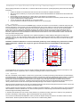
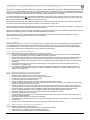
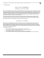
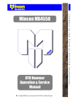
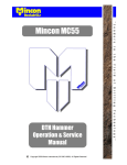
MR120
Operation and Service Manual
Copyright © Mincon 2012, All Rights Reserved.
Table of Contents
1.
INTRODUCTION ........................................................................................................................... 3
2.
INSTALLATION AND OPERATION.............................................................................................. 3
2.1
SAFETY ........................................................................................................................................................... 3
2.2
HAMMER CARE. ............................................................................................................................................... 3
2.2.1
Storage .................................................................................................................................................... 3
2.2.2
Commissioning........................................................................................................................................ 3
2.2.3
Lubrication............................................................................................................................................... 4
2.2.4
Operation ................................................................................................................................................ 4
2.3
SERVICING ...................................................................................................................................................... 5
2.3.1
General ................................................................................................................................................... 5
2.3.2
Opening Chuck and Backhead ............................................................................................................... 5
2.3.3
Dismantling Hammer to Change Drill Bit ................................................................................................ 5
2.3.4
Disassembly for Full Servicing of Hammer ............................................................................................. 5
2.3.5
Inspection ................................................................................................................................................ 6
2.3.6
Checking Wear Limits ............................................................................................................................. 6
2.3.7
Reassembly ............................................................................................................................................ 6
3.
TROUBLE SHOOTING ................................................................................................................. 8
4.
APPENDIX .................................................................................................................................... 9
5.
4.1
REVERSE CIRCULATION HAMMER EXPLODED VIEW AND PARTS LIST AND TECHNICAL DATA................................ 9
4.2
HAMMER SERVICE LOG ................................................................................................................................. 10
WARRANTY ............................................................................................................................... 11
Mincon Rockdrills – “The Driller’s Choice”
Page 2
1. Introduction
Thank you for choosing the Mincon MR120 Down-the-Hole hammer. Please read this manual carefully before using your
hammer in the interests of safety, warranty and best operational care. The Mincon MR120 is manufactured with specially
selected materials and heat treatment to withstand the stresses of drilling in the most extreme conditions. Internal components
are manufactured to meet finely matching tolerances to provide fast drilling, reliability and efficient use of air without waste.
With correct care your Mincon MR120 hammer should provide you with top performance reliability and long service life.
Warranty is provided by Mincon as per the warranty section 5.
Please keep this instruction manual as a permanent record for your Reverse Circulation Hammer.
The specifications and instructions contained in this manual are based on the up-to-date information as at publication date.
2. Installation and Operation
2.1
Safety
Be sure to work safely at all times. Wear protective clothing and safety equipment and observe all safety regulations as
prescribed by your employer, Government, or the site on which you work. Do not wear loose clothing that may get caught in
rotating parts and cause serious personal injury.
Remember that a “Reverse Circulation” percussive hammer emits noise and you should therefore take every precaution to
safeguard your hearing against damage by using proper ear protectors. Use eye protection at all times. Rock chips and dust
which may be discharged from the face of the bit or bore hole at high velocities and can cause severe injury.
Hammers can be heavy – Always use proper and approved lifting equipment and take every precaution to safeguard yourself
against injury. Keep hands clear at all times – Beware of getting fingers trapped between the chuck and bit and do not use
hands or feet to clear the top of the borehole at any time.
Other safety advice is given throughout this document which you are advised to read.
2.2
2.2.1
Hammer Care.
Storage
It is important to take the following steps in order to ensure smooth operation when hammer is to be re used.
When the hole is completed and the hammer is to be inactive for some time the following steps should be taken.
Short Term Storage (e.g. 1 -2 weeks)
•
Using high pressure air, blow the hammer clear of all water.
•
Turn automatic oiler up full and cycle hammer until oil is running out the shank of the drill bit.
•
If there is not an automatic oiler, pour 1 litre (2 pints) of rock drill oil in to the back head/Top sub.
•
Turn the air on and cycle for 10 seconds. This will lubricate the internal parts.
•
Seal the hammer at the back head/Top sub and chuck end with a rag to exclude any dust or foreign particles.
•
Store the hammer horizontally in a clean dry environment.
Long Term storage (e.g. 1 month or longer)
•
Using high pressure air, blow the hammer clear of all water.
•
Break out the back head and chuck on the rig as it is easier to do it here than back in the workshop.
•
Disassemble the hammer.
•
Inspect and clean all hammer components.
•
Lubricate all the internal components with rock drill oil.
•
Reassemble the hammer, and seal the back head and chuck end.
•
Store horizontally in a clean and dry environment.
Before restarting any hammer after prolonged periods of inactivity, disassemble and inspect all internal parts. Clean and
remove any oxidation with an emery cloth. Re-lubricate all internal components with rock drill oil and reassemble the hammer.
Full assembly and disassembly instructions can be found further on in this manual.
2.2.2
Commissioning
Always use drill bits in good condition (sharpened). Using overrun bits can affect the life of the bit, chuck/chuck sleeve and
reduce penetration rates which can damage internal components due to the non transference of energy in to the rock being
drilled.
Mincon Rockdrills – “The Driller’s Choice”
Page 3
When starting a hammer for the first time, or a hammer that has been stored for a prolonged period, please follow the following
instructions.
•
•
•
•
•
•
2.2.3
Grease the threads on the back head and chuck and fit to the hammer complete with drill bit.
With the bit in the breakout pot, torque up the hammer until the standoff between the backhead and wear sleeve has
closed up.
Before adding the first drill rod pour 1 litre(2 pints) of rock drill oil in to the back head.
Ensure all drill rods are blown clean of any dirt and debris and that all threads are cleaned, greased and all o rings are
in good condition before coupling together.
Turn on air and blow until oil starts to run out of the bit shank.
Cycle the hammer on half air for the first few minutes to run in internal parts.
Lubrication
It is vital for DTH hammers to receive a constant supply of proper rock drill oil in to the air stream, to lubricate and protect the
internal components, and to provide a good air seal between the piston and its matching component parts for efficient drilling. It
is recommended that an automatic oiling system be used when operating your hammer. Too much oil can cause hydraulic
locking in the hammer. Drilling with insufficient lubrication will cause the hammer to run dry and cause premature wear or
failure. The correct consumption of oil/oil type is dependent upon the air volume and ambient conditions. Please refer to the
lubrication graph below for recommendations. There should be visual evidence of oil around the drill bit shank and within the
tube joints when changing tubes.
The recommended grade of oil is dependent on the ambient temperature in which drilling is taking place as well as the
operating pressure. As a rule of thumb, ISO320 grade rock drill oil should be used whenever possible as the hammer is a high
frequency tool, however, where the pump cannot pump the oil in colder conditions, a lower viscosity of oil can be used as per
the graph below.
Remember: Insufficient lubrication or incorrect lubrication grades may result in damage being caused to the hammer
and its components. Hydraulic oils, engine oils, gear oils and diesel are not recommended for lubricating DTH
hammers.
3
4
5
42.0
1250
35.0
1000
28.0
750
21.0
500
14.0
250
7.0
2
8
4
6
US Pints/Hour
10
Ambient Temperature ºF
2
Air Volume – M3/MIN
Air Volume - CFM
1
1500
100
37.8
80
ISO320
60
26.7
15.6
40
4.4
20
ISO150
0
-6.7
-17.8
Ambient Temperature ºC
120
Pressure - Bar
6.9 13.8 20.7 27.6 34.5
48.9
Litres/Hour
ISO40
-20
-28.9
100 200 300 400 500
Pressure - PSI
At low temperatures of 5ºC (41ºF), and in hot humid conditions with higher air pressures, when hammers can freeze up. Antifreeze additive may be required at a rate of 1-2 litres (2-4 pints) per hour or more as necessary.
2.2.4
Operation
Be sure to familiarise yourself with the controls of the rig and work in accordance with the rig manufacturers recommendations.
The hammer begins to operate as the air supply is turned on and when the drill bit is pushed firmly into the hammer. Excessive
thrust pressures are not needed to make the piston cycle. The thrust controls on the drill should be adjusted to the correct
pressure and should be readjusted to take account of the weight of any extra drill rods added, so that the thrust pressure
remains constant and not excessive. Insufficient thrust pressure will make the hammer drill erratically and less efficiently and
cause premature wear to the bit and chuck splines with likely damage to the hammer components and threads.
When the hammer is lifted from the rock face, the drill bit extends from the chuck and the percussive action ceases. The air will
pass through the hammer, which can be used to flush the hole clean.
Rotation speeds should be selected to suit drilling conditions and drill bit diameters. High rotation speeds can cause premature
wear of drill bits, hammers and drill rods. Too slow a rotation speed can cause binding in the borehole and damage to drill bit
inserts through the snatching rotation action.
In hard and soft formations of rock, the aim of the hammer is to penetrate smoothly at the rate of 10mm (0.375”) per drill rod
revolution. Generally in softer geology, higher rotational speeds can give better results.
The controls of the drill should be adjusted in order to provide the largest drill chip size with the smoothest rotation and feed
characteristics. Rotation speeds should be set to suit the rock conditions being drilled.
Mincon Rockdrills – “The Driller’s Choice”
Page 4
Some ground conditions may cause binding within the hole, with the added risk of the hammer, drill bit and drill string becoming
jammed. Any excessive pullback forces or high rotation speeds used in an attempt to recover the drill string may generate heat
zones around the hammer, which may affect the metallurgy of the components to cause damage and ultimate premature failure.
A backreamer sub may help reduce jamming in bad ground conditions and prevent heat damage.
It is recommended that you do not pour diesel into the hammer if it becomes bogged. However if this is done, there is the risk
an internal combustive effect if the hammer is fired while there is diesel in it. This will damage the hammer and its components.
Any heat induced failures are not covered by our terms of warranty.
Before adding drill rods make sure that the threads are clean, well greased and all O rings are in good condition. Ensure that
there are no contaminants likely to enter the hammer to cause damage and early wear.
It is recommended that proper drill guides and break out systems be used which suit the diameter of the hammer. All tools and
spanners used for the drill bit and break out flats should fit properly.
Make certain that the hammer is stationary when applying spanner or breakout tools. Do not rotate the hammer with a spanner
attached to the drill string unless it is safely captivated within the breakout clamp.
All internal hammer O rings, check valve and check valve seal should be examined and replaced periodically, to ensure
optimum performance and effective sealing from borehole ingress.
2.3
Servicing
2.3.1
General
Dismantling the Hammer for servicing or to change the bit can be made easier if the chuck threads are regularly greased and
the backhead threads are well greased any time the hammer is opened for servicing. We recommend that a good quality
thread grease be used, and in acidic conditions, we do not recommend copper based greases as this can trigger a galvanic
reaction with corrosive effect to damage the root of the threads and cause failure.
2.3.2
Opening Chuck and Backhead
To open Mincon DTH hammers please adhere to the following instructions.
•
The threads used in Mincon Hammers are right hand threads. Therefore they loosen in an anti-clockwise direction.
•
Please use a bit breakout pot to hold the drill bit when opening the chuck.
•
Please ensure that the wrench is not placed on the threaded section, or the piston running area of the Wear Sleeve.
•
Break out wrench jaws should be in good condition. It is good practice to keep a spare set of jaws with the rig.
•
Do not strike or hit the outer components as this could weaken the heat treated steels, and distort accurate running
diameters.
•
Hitting the hammer may also cause hard metal fragments to be chipped off which may be projected and cause
personal injury or eyesight loss.
•
Do not apply heat to the hammer, as this can alter the metallurgical composition and result in premature failure.
•
Take care when dismantling the hammer to make sure that parts and drill bits do not become detached and cause
damage or personal injury.
2.3.3
Dismantling Hammer to Change Drill Bit
When changing the drill bit please follow this procedure.
•
Please follow the opening instructions from section 2.3.2.
•
Remove the bit retaining rings form around the top of the bit shank.
•
Lift the chuck sleeve over the threads of the chuck.
•
Remove the chuck from the shank of the bit.
•
Inspect the splines and threads of the chuck for damage, excessive wear or galling.
•
Inspect the sample tube end wear. Be careful checking sample tube wear as the end can be extremely sharp. Always
change the sample tube before it is worn out.
•
Inspect the face of the piston for any pitting or cracking on the strike face. If there is any damage then it should be
replaced. Please do not inspect the piston while it is suspended on the drill rig. Always do this with the hammer in a
horizontal position. If the piston nose is damaged it is likely that the Aligner/Bearing bush is damaged as well.
•
Inspect the Aligner/Bearing bush for any damage. If there is any damage then it should be replaced.
•
Grease the threads on the chuck and place the chuck down over the splines of the bit.
•
Place the Chuck sleeve on to the chuck.
•
Ensure that the gauge diameter of the drill bit and the diameter of the chuck sleeve have the running clearance you
require for effective sampling.
•
Place the bit retaining rings over the top of the bit shank.
•
Screw the chuck bit assembly in by hand to ensure that the sample tube does not get jammed up in the bit when fully
shouldered up.
•
Torque up the hammer with the bit in a bit break out pot to ensure it does not run loose.
2.3.4
Disassembly for Full Servicing of Hammer
For full disassembly please follow these instructions.
•
Where possible carry out disassembly in a clean work shop environment.
•
Break out the back head and chuck as described previously.
•
Mark the ends of the wear sleeve as chuck and back head end.
Mincon Rockdrills – “The Driller’s Choice”
Page 5
•
•
•
•
•
•
•
•
•
•
•
•
2.3.5
Secure the hammer in a chain vice to hold steady.
Remove the check valve and spring from the top of the Sample tube.
At the chuck end of the hammer, push the sample tube end in to the hammer with a piece of wood. Be careful as this
end can be very sharp from wear.
From the opposite end pull the sample tube out of the hammer.
Remove the sample tube spacer from the sample tube and then remove the Lock ring from inside the hammer on top
of the Sample tube mount.
From the chuck end, insert a soft steel drift in to the hammer against the piston strike face.
Carefully knock the piston out the back head end of the hammer. This will push the Inner cylinder/sample tube mount
assembly out of the hammer as well. Do not use the sample tube for this process as it would damage it.
To remove the Aligner bearing bush, reverse the direction of the piston (the strike face towards the back head end)
and with the soft steel drift against the piston strike face, carefully knock the Aligner out the chuck end of the hammer.
Push the piston out of the back head end of the hammer.
As the wear sleeve for MR series RC hammers are not reversible, it is not necessary to remove the piston retaining
ring. However, if required, please do as follows.
Insert a long flat head screw driver in to the groove in the piston retaining ring and lever the ring clear from the wear
sleeve groove. Using a hook, pull the ring out of the wear sleeve.
The back head is disassembled as so: remove the circlip from its groove and lift the adaptor tube out with the screen
assembled around it.
Inspection
Prior to inspection, thoroughly clean all parts using a suitable cleaning agent. Diesel is not recommended for cleaning as it can
cause corrosion to components, and damage to health.
All parts should be visually inspected for any signs of damage, wear or cracking. The inner cylinder, wear sleeve and lock rings
can be checked for unseen cracking by suspending them and lightly tapping with a screw driver. If they emit a ringing tone then
they should be sound. However, a dull flat tone if emitted may indicate cracking, and the part should be replaced.
Take particular care to check the internal bore of the wearsleeve for pick-up marks and galling. If these are present, the barrel
of the wear sleeve should be honed out, using a hand hone to remove them. It is usual that if there are signs of damage or heat
checking on one part that there is also the same on mating parts.
Inspect surface of the piston for pick-up marks and galling (usually caused through poor lubrication or the presence of
contaminants) and smooth out with emery paper or a hand held grit stone. Where galling of the piston has occurred, substantial
heat has been generated and quite often, micro cracking has occurred on the piston. In these cases, the piston should be
replaced if there is evidence of such cracking. Check the strike face of the piston for cracking or damage.
Inspect the Aligner for any galling or cracks. If either is present, then the aligner should be replaced.
All internal hammer O rings, check valve and check valve seal should be examined and replaced periodically, to ensure
optimum performance and effective sealing from borehole ingress.
If there has been any sanding or polishing of parts then it is critical that these parts are thoroughly cleaned before re assembly.
2.3.6
Checking Wear Limits
The performance of the hammer is dependent on the designed running clearances of critical components. These should be
measured and recorded in the Service log in the appendix. The service log gives the location of where measurements should
be made. Depending on how many parts need to be replaced to bring the hammer back to optimum performance, it may be
economical to replace the hammer all together.
2.3.7
Reassembly
The hammer can be reassembled in the following manner, referring to the exploded view of the hammer in the appendix.
Ensure all components, except for the sample tube, are liberally coated with good quality rock drill oil and threads with thread
grease. Replace all O rings and check valve seal before re assembly.
•
Identify the chuck end of the hammer and stand with the chuck end facing up. Insert the piston retaining ring in to the
groove provided. Ensure the extraction groove on the retaining ring is facing the chuck end of the hammer.
•
Insert the Aligner (with the smaller outside diameter facing the piston retaining ring) in to the wear sleeve. Using a soft
steel drift, tap the aligner in to place against the piston retaining ring.
•
Place the bit retaining rings on top of the aligner.
•
Screw the chuck (with the chuck sleeve assembled on it) in to the wear sleeve.
•
Seal up the chuck end of the hammer.
•
Turn the hammer over so the back head end is facing up.
•
Insert the Piston in to the wear sleeve (refer to the exploded view for orientation).
•
Insert the Sample tube mount in to the inner cylinder and fit the seating rings around the round holes on the inner
cylinder.
Mincon Rockdrills – “The Driller’s Choice”
Page 6
•
•
•
•
•
•
•
•
•
•
Insert the Inner cylinder assembly in to the wear sleeve. Tap the assembly in to place using a soft steel drift.
Place the lock ring on top of the sample tube mount.
Fit the spacer on to the sample tube with the flat face facing down to the drill bit end of the sample tube. Place the
check valve spring on to the locating recess on the spacer and fit the check valve in to place.
Spray the area under the rings of the sample tube with penetrating oil (e.g. CRC / WD40). If hammer oil is used then
the sample tube will not go in to place properly because a hydraulic lock will occur between the sample tube shoulder
and the sample tube mount.
Insert the sample tube assembly in to the hammer.
Pour hammer oil in to the hammer.
Fit the screen to the adaptor tube and insert the assembly in to the back head. Insert the circlip in to the back head to
lock the assembly in to place.
Screw the back head assembly in to the wear sleeve. There should be a standoff gap of between 0.5mm - 1mm
(0.020” – 0.040”) between the back head and wear sleeve shoulders. If the shoulders meet up then the lock ring needs
to be replaced so that all internal parts are properly locked in place. Seal up the top of the hammer.
Store the hammer on its side and rotate it periodically if it is being stored for an extended period of time.
If a hammer is to be stored for a long period of time, we would recommend that the hammer be disassembled, oiled
up, and stored in a clean, dry environment.
Mincon Rockdrills – “The Driller’s Choice”
Page 7
3. Trouble Shooting
Problem
Possible cause
Remedy
Low penetration
and high pressure
External drill clearances are worn.
Change or re-sharpen the drill bit. Make sure that the running
clearance on the bit seal is what you need for the drilling
conditions.
Open hammer and clean the obstruction
Set the feed pressure until the rotation starts to bind. Then back
off the feed pressure until the rotation runs smoothly
Drill bit peripheral rotation speed of 12 – 15” per second (300380mm). Place chalk mark on drill rod and check the advance
revolution. If greater than ½” (12mm) per revolution increase
rotation until the advance per revolution is a maximum of
between 3/8” – ½” (10-12mm)
Inspect piston, inner cylinder, wearsleeve and bearing against
discard measurements, and discard as necessary
Ensure there is an oil film coming from bit spline and bit parts.
(Place cardboard under bit to check)
Rough or erratic
operation
Contamination in hammer
Too much feed pressure
Rotation speed too slow
Low penetration /
Low pressure
Worn drill clearances
Lack of oil
Sudden loss of
pressure
Over run/ blown out sample tube.
Check sample tube wear regularly, and change before it is worn
out.
PART FAILURE
Remedy
Problem
Possible cause
Cracked wear
sleeve/ external
part distortion.
Abuse of wearsleeve
Avoid welding, heating or torque wrenching in the wrong place
as outlined in section 1.4. Note also section 1.6
Worn wearsleeve
Outside diameter has worn beyond the discard point. Measure
casing O/D approx. 75mm (3”) from chuck end and backhead
end and replace if necessary.
If drilling in a corrosive environment wash internal and external
parts regularly to avoid corrosive impact on the drill.
If such danger is imminent use a dig out sub.
Corrosion
Piston cracked
through large
diameter
Piston strike end
breaking
Bogged Drill can lead to reaming
and overheating distortion of the
drill.
Drill bogged can lead to chuck,
wear sleeve and chuck sleeve to
distort.
Lack of lubrication causes microcracks leading to breakage
Feeding hard through voids on
broken ground can cause
wearsleeve to distort causing heat
cracks and galling on the piston
Using wrench over wrong area to
open drill can cause the wear
sleeve to distort.
Insufficient down-force
Over running sample tubes will
allow ingress between the two
striking faces and cause piston
nose to crack.
Mincon Rockdrills – “The Driller’s Choice”
Inspect all parts thoroughly if drill is recovered, and replace
parts where necessary.
Check lubricator and ensure oil film on the bit splines.
Use light feed and ensure the hole is kept clean and
consolidated. Use foam or mud if necessary
Use wrench only in the
Area indicated.
Increase feed until rotation binds and pressure pulses and then
back off until the rotation and pressure becomes smooth
Replace sample tubes before they are worn out.
Page 8
4. Appendix
4.1
Reverse Circulation Hammer exploded view and Parts List and Technical Data
1
19
2
20
3
21
4
5
6
Item
1
2
22
3
7
4
5
6
7
8
9
10
23
11
12
13
24
25
14
26
27
28
29
30
15
31
16
17
18
Specifications
Hammer Outside Diameter
Hammer Length (Less Drill Bit)
Backhead Spanner Flat Size
Drill Bit Shank Type
Drill Bit Size Range
Hammer Weight (Less Bit)
Maximum Drill Bit Weight
Piston Weight
Backhead Stand Off
Recommended Minimum Air Package
Mincon Rockdrills – “The Driller’s Choice”
8
9
10
11
12
13
14
15
16
17
18
19
20
21
22
23
24
25
26
27
28
29
30
31
Description
Part Number
Mincon MR120 RC Hammer – 4” Remet
Mincon MR120 RC Hammer – 4” Metzke
Mincon MR120 RC Hammer – 4 ½” Remet
Mincon MR120 RC Hammer – 4 ½” Metzke
MR120AS01
MR120AS02
MR120AS03
MR120AS04
Internal Circlip
O Ring (4” Remet Only)
O Ring (4 ½” Remet Only)
Adaptor Tube – 4” Remet
Adaptor Tube – 4” Metzke
Adaptor Tube – 4 ½” Remet
Adaptor Tube – 4 ½” Metzke
O Ring
O Ring
Air Screen
Backhead – 4” Remet
Backhead – 4” Metzke
Backhead – 4 ½” Remet
Backhead – 4 ½” Metzke
O Ring
Check Valve Seal – Nitrile U Seal
Check Valve
Check Valve Spring
Spacer
Lock Ring
Sample Tube
O Ring
Sample Tube Mount
O Ring
O Ring
O Ring
Seating Ring
Inner Cylinder
Piston
Wear Sleeve
Piston Retaining Ring
Aligner
O Ring
O Ring
Bit Retaining Ring
O Ring
Chuck
Chuck Sleeve
D1300-0780
BS-226
BS-228
MX5053AT01
MX5053AT11
MX5053AT21
MX5053AT31
BS-224
BS-040
MX5053SC01
MR120BH01
MR120BH11
MR120BH21
MR120BH31
BS-241
8406-175
MX5053CV01
MX5053SP01
MX4550SS01
MX4550LR01
MR120ST03
BS-228
MR120DR01
BS-226
BS-234
BS-040
MX5053SR01
MR120IC01
MR120PN01
MR120WS01
MX5053PR01
MR120BB01
N7 92x4
BS-237
MR120BR01
BS-152
MR120CK01
MR120CS139
Metric
Imperial
120mm
1165mm
94mm
4.75"
45.9"
3.7”
MR120
127mm- 143mm
70 Kgs
14.5 Kgs
14.5 Kgs
0.75mm
3
25.5 m /min @ 24.1Bar
5" – 5.625"
154 Lbs
32 Lbs
32 Lbs
0.030”
900 cfm @ 350 psi
Page 9
4.2
Hammer Service Log
WEARSLEEVE / PISTON CLEARANCE
Part
New Dimension
As Measured
Wear
Wearsleeve ID
A
4.040” (102.61mm)
C
C-A
Piston OD
B
4.035” (102.50mm)
D
B-D
Actual Clearance
Discard
Clearance
≥ 0.010”
(0.25mm)
C-D
Chuck end
D
C
INNER CYLINDER / PISTON CLEARANCE
Part
New Dimension
As Measured
Wear
Cylinder ID
A
3.740” (95.00mm)
C
C-A
Piston OD
B
3.735” (94.87mm)
D
B-D
Actual Clearance
≥ 0.010”
(0.25mm)
C-D
D
Discard
Clearance
C
ALIGNER / PISTON NOSE CLEARANCE
Part
New Dimension
As Measured
Wear
Aligner ID
A
3.248” (82.50mm)
C
C-A
Piston Nose OD
B
3.238” (82.25mm)
D
B-D
D
Mincon Rockdrills – “The Driller’s Choice”
Actual Clearance
Discard
Clearance
≥ 0.015”
(0.38mm)
C-D
C
Page 10
5. Warranty
Mincon DTH HAMMERS
Warranty, October 2002
Mincon warrants that the Mincon DTH Hammers and spare parts therefore, manufactured by Mincon and delivered to the initial
user to be free of defects in materials or workmanship for a period of 3 months after initial operation or 6 months from the date
of shipment to the initial user, whichever occurs first. Mincon may elect to repair the defective part or issue full or partial credit
towards the purchase of a new part. The extent of credit issued will be determined on a pro-rata basis bearing in mind the
service life of the defective part against the normal service life of that part. The part will be replaced or repaired without charge
to the initial user at the place of business of an authorized Mincon distributor during normal working hours. The user must
present proof of purchase at the time of exercising the warranty.
The warranty applies only to failures resulting from defects in the material or workmanship and does not apply to failures
occurring as a result of abuse, misuse, corrosion, erosion, negligent repairs and normal wear and tear. Failure to follow
recommended operating and maintenance procedures which result in component failure will not be considered for warranty.
This warranty is in lieu of all other warranties, other than title, expressed or implied.
Limitation of Liability
Mincon will not accept any remedies to the user other than those set out under the provisions of warranty above. The total
liability of Mincon or its distributors with respect to the sale of DTH Hammers or spare parts therefor, whether based on
contract, negligence, warranty, indemnity or otherwise shall not exceed the purchase price of the product upon which such
liability is based. Mincon and its distributors shall in no event be liable to any party relating to this sale for any consequential,
indirect, special or punitive damages arising out of this sale or any breach thereof, or any defects in or failure of or malfunction
of the Mincon DTH Hammer or spare parts.
Warranty will be voided where:
•
•
•
•
•
There is evidence of damage resulting from insufficient or incorrect lubrication.
There is evidence of misuse through the application of heat, welding or of being struck.
There is evidence of distortion or bending however caused.
There is damage caused as a result of using incorrect servicing tools or procedures.
If it is evident that the hammer or its components have achieved a reasonable proportion of their anticipated life.
Mincon Rockdrills – “The Driller’s Choice”
Page 11