1
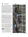
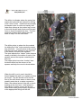
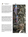
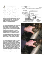
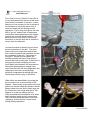
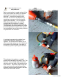
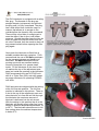
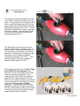
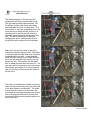
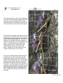
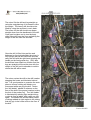
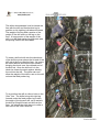
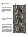
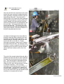
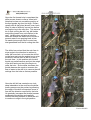
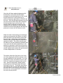
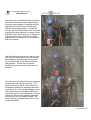
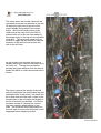
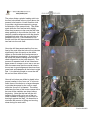
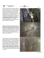
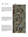
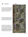
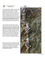
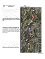
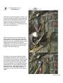
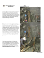
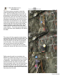
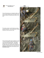
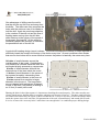
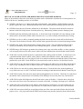
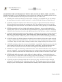
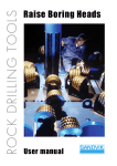
Page 1 PHQ250 ROCKDRILLS OPERATING MANUAL PHQ250JHMAVL Anti-Vibration Jackleg PHQ250JHML Standard & Muffled Jackleg HOW TO DRILL A DRIFT ROUND Version 200802 Page 2 Before beginning the miner will mark up the face of the drift or tunnel according to size with a grid that pinpoints the location for each hole to be drilled in the round. The “line” (direction) for the drift round Is usually predetermined by engineering and sighted in from “line plugs” installed by surveyors. A nine foot high by twelve foot wide heading will usually have five vertical lines spaced three feet apart and four horizontal lines spaced three feet apart. A blasthole is to be drilled at the intersection of each line of these lines. Here the driller is indicating the horizontal line marked for the “back” holes. Marking up the round starts from the centerline painted on the face from the line provided by surveyors. Here the driller is indicating the intersection of the line for the “breast” holes where it meets the center line. The star indicates the center of the drift round. The “cut” is always drilled between the horizontal line for the “breast” holes and the horizontal line for the “knee” holes in either of the two squares having one side as the center line. It is normal practice to alternate the area where the “cut” is to be drilled each time a new round is drilled to be on the safe side and avoid any “bootleg” holes from the previously blasted round. The mining act prohibits collaring holes near “bootlegs.” The driller indicates where the “burn cut” is to be drilled. This area is where it is easiest to collar and drill holes and near the center of the “round” so the blasting sequence can radiate out from the “cut. The six holes that make up a standard “burn” cut are individually painted on the rock face in a pattern similar to this. The large holes are first drilled with regular bits and then reamed with a three inch (76mm) reamer bit. The reamed holes are not charged with explosives and not blasted. Version 200802 Page 3 The driller is indicates where the center line meets the horizontal line marked for drilling of the “knee” holes. Knee holes are usually the easiest holes to collar and usually drill faster than others as the pusher leg is more in line with the drill and exerts more forward force on the drill towards the face. The firm pressure of the bit face against the rock tends to help it cut the rock faster. The driller points to where the line marked for drilling the “lifter” holes meets the center line of the drift. You will notice in this picture that there are dots painted on the rock face in the center of some of the squares. The dots indicate four “helper” holes that are usually to drilled in the center of each of the squares around the square containing the burn cut. The helper holes have less “burden” than the holes drilled on the corners of the squares and help the round to break better. When the drill is not in use it should be leaned against the wall in an upright position as shown. The drill should not be on the floor of the drift where water or debris could possibly enter the air or water connection tubes, the exhaust ports of the drill or chuck bushing at the front end. A drill placed in this position is ready to have the air and water hoses easily and properly connected to the appropriate fittings on the drill. Version 200802 Page 4 The driller is showing how the steel retainer moves up to allow a drill steel to be placed in the chuck and close over the collar to prevent the drill steel from escaping the drill. The retainer should be checked at the beginning of each shift to be sure that it has the proper tension to work properly. The inner side of the retainer is examined to insure that matching face of the retainer has not been worn away by the collars of the drill rods to a state where the device no longer holds the collar of the steel in the chuck or could cause damage to drill rods. The driller is checking that the leg coupling is tight to the drill body so that there is no air leakage when the drill is in operation. The swivel action of the drill on the leg presents a possible hazard of pinching hands or fingers between the bottom of the drill and the leg. The driller needs to remain vigilant not to place his hands or fingers in harms way between the drill and leg connection. The driller’s hand is on the throttle control handle that controls the flow of air entering the drill to power the hammering of the piston in the drill. This handle can be pulled fully back to introduce a full flow of air to the front end for blowing out drill rods while in the hole. The throttle handle should be left in the neutral position and the feed control handle in the reverse position when the drill is not in use. Should someone turn on the air to the drill with the controls in the proper positions the drill will not begin to operate prematurely. Version 200802 Page 5 A driller controls all operations of the drill and the leg from the backhead of the PHQ250 Jackleg drill. The schematic at the right shows positions of the operating controls on the backhead. The throttle handle controls the flow of air to the hammer inside the drill. The positions of the handle in hammer mode are steadied by a ratchet mechanism in the backhead. When the handle is turned back to the extreme all the air flow to the drill is directed to the front end to flush out the drill hole. The feed control handle provides the air flow for thrust or retraction of the feed pusher leg. The driller’s hand grips the feed control hand with his thumb hovering over the retract button located on the feed control handle. When the button is in the position indicated the leg retract feature is not in use. When the leg retract button is pushed compressed air flows to the bottom of the leg piston forcing it to retract into the leg. (The driller’s hand is shown without gloves for purpose of clarity. Drillers must wear gloves as part of their protective clothing.) The retract feature is very useful to a miner during drilling operations. When the leg reaches the end of the extension travel with distance remaining between the front of the rock drill and the rock face the drill and leg can be repositioned without moving the drill set-up. The driller can retract the end of the feed leg to a position closer to the drill by slowing the hammer and pushing the retract button. Once the leg retracts the miner advances the throttle hammer to continue drilling the remaining distance to take the front end of the drill to the collar of the hole. Version 200802 Page 6 Connecting the water hose to the drill is a straightforward process. The inside of the water tube swivel and the end of the water hose should be visually checked to be sure there is no debris inside. The hose usually has a water control valve located near the connection to the drill to enable the driller to turn the water on an off. The driller needs to reduce the water flow for slow collaring of holes and return it to full flow once the bit and steel have entered the rock and the hammer is drilling at full force and this valve needs to be close by. Connections are standard NPT threaded hose fittings shown in the picture. The driller uses his mine wrench to tighten the nut securely on the NPT thread on the water stem so that there is no water leakage. A hose whip is not required for water connections as the water pressure is low enough that flow would not whip the hose around when the hose is disconnected. Alternate fitting are “Sure-Lock” quick connect fittings that allow the driller to quickly connect or remove the hose. One must ensure the locking pin is in place when using sure-lock connections. Before connecting the air supply hose crack the valve at the end of the supply hose and “blow the hose” to remove any accumulated condensate water or debris that may have entered the hose while disconnected. Blow the main supply hose and connect it to the short supply hose and blow that hose as well. Blow hoses until any visible water vapour coming out of the end of the hose disappears. Shut off the valve and connect the lubricator and short hose. Version 200802 Page 7 Pour a half of a cup (100ml) of rock drill oil or rock drill grease into the end of the short hose where it connects to the drill. It often takes up to five minutes for the oil misted in the lubricator to travel the twelve feet of hose and reach the drill during normal operations. This is long enough for the rock drill to “go dry” and the lack of lubrication could cause serious damage to the interior parts of the rock drill within minutes. The small amount of rock drill oil will provide lubrication to the drill until the air misted oil arrives from the lubricator. Connect the short air hose to the air bend swivel connection on the drill. The short hose must be no longer than twelve feet (four meters) between the lubricator and the air connection to the drill. If the miner is using NPT fittings he must tighten the threads securely and use a hose whip to prevent the hose coming free. If the miner is using quick-connect couplings he must insert safety pins between the connections. Should the pressurized air supply hose come free from the drill during operation the whipping of the hose caused by high pressure compressed air exiting the hose could cause serious injury to the driller. When drills are assembled in the shop the air connection nut is secured with a Tab Washer. When a drill is returned to the work place from the drill shop the operator should always check the rock drill to make sure the Air Connection Nut is tight and that a Tab Washer is in place to secure the nut. PHQ recommend the installation of a “hose whip” between water and air connections. The hose whip prevents the air hose from “whipping” around should it come loose during drilling operations. Version 200802 Page 8 Before opening the air supply to the drill the miner must check the amount of lubricant remaining in the reservoir of the in-line lubricator. Insure the air supply to the lubricator is turned off and bleed off any remaining air pressure in the line before opening the lubricator. For this purpose PHQ recommends that an air valve be installed near the lubricator to make it convenient for the miner to shut off the air. The lubricator should be installed no further than twelve feet (four meters) from the drill for most efficient use of the misting of the oil or grease from the lubricator. It is critical to prevent dirt or debris from entering the lubricator whenever it is opened. The miner should always use a clean rag to wipe away any dirt or debris on the outside of the lubricator in the area of the filler plug before opening the lubricator. The lubricator is brought to an upright position with the safety filler cap on top. The lubricator cap is usually easily unscrewed with the use of the side of the handle of the mine wrench. Should the cap be tight the miner can loosen the cap by hammering sideways on the square corners of the filler cap to get the threads started. Version 200802 Page 9 The PHQ lubricator is equipped with a safety filler plug. The threads on the plug are straight threads (not tapered) and will hold the plug until it is fully unscrewed. The plug has a hole drilled from inside the cap in a manner that allows air to escape to the outside before the thread is fully unscrewed. There will be a loud hiss of escaping air to warn the driller if the air line is still under pressure. Should the driller hear the hiss he must re-tighten the cap and make sure the air valve is closed, then he needs to drain off any pressurized air before opening the filler plug again. Once open the lubricator is filled from a suitable portable lubricant container. PHQ recommends the use of Oil Safe containers for the transport storage and handling of lubricants. Oil Safe containers have a pouring spout with an excellent sealing closure to keep the oil or grease clean inside. Fill the lubricator so the level of the oil reaches the top of the adjustment post seen just inside the opening in the lubricator. PHQ recommends the use of EP100 rock drill oil or Triple Zero (000) rock drill grease as proper lubricants for operating PHQ250 rock drills. PHQ lubricators are shipped with the setting at the full flow rate position. The full flow position is indicated in this picture. There is a slot in the top of the adjustment post and when that slot is in line with air flow through the lubricator the maximum amount of lubricant is delivered into the air stream. With the setting in this position the oil in the lubricator will usually empty after four hours drilling in ambient temperatures between 10º to 20º C. The lubricator should be set to full flow setting when the ambient temperature is below 5º C. Version 200802 Page 10 The setting post can be turned with the use of the end of a metal hose clamp or screw driver. Turning the post to an angle at 45º to the air stream will reduce the flow of oil by approximately 50% when drilling in ambient temperatures between 10º to 20º C. At this setting the lubricator will usually empty after six hours of drilling. The lubricator should be set at this level for drilling in ambient temperatures above 25º C The adjustment post can be turned to a position with the slot at an angle of 90º to the air stream. In this position the flow of oil is at the lowest setting (nearly off) and the lubricator will empty of oil or grease usually after eight hours of drilling in ambient temperatures between 10º to 20º C. This setting should be used when drilling in ambient temperatures over 35º C. PHQ recommends the use of Vultrex Triple Zero EP000 Rock Drill Grease as the lubricant of choice for PHQ250 Rock Drills. Vultrex grease was designed to for air misting in the PHQ football style lubricator and PHQ F61 Large Capacity Lubricator PHQ also recommends that the your choice of rock drill grease or rock drill oil be stored, carried and dispensed from Oil Safe containers. The Oil Safe containers are designed specifically to keep oil clean and free from contaminants in the most hostile of environments yet are fabricated from light weight durable plastic materials. Version 200802 Page 11 The driller prepares to lift and carry the assembled rock drill complete with hoses. The drill and leg weigh approximately 100 lbs (45kg) however the hoses add weigh and drag when the drill is transported. The correct way to carry an assembled drill in the work place is to place the drill and leg in a vertical position and lift the drill with your shoulder placed under the backhead of the drill. The driller has his drill in the right configuration and is indicating the area of the drill that will be placed on his shoulder. Make sure the area of travel is free from obstructions before lifting the drill. The driller is indicating the shoulder where he will place the backhead of the drill. A right handed driller will carry the drill on his right shoulder as he will be using his right hand to lift and steady the drill. This leavess his left hand free to steady the drill while he carries it. He can also use his left hand to move the hoses should they get caught or to move anything that is in the way of placing the drill where it will be used The driller is indicating the handle on the leg which will be used to help carry the drill once it has been lifted to his shoulder. The driller is checking the hoses to be sure they are not caught on anything thing that may hinder him in carrying the drill and to be sure that the hoses will follow along behind while he is carrying the drill. Version 200802 Page 12 The miner prepares to lift the drill standing to one side of the drill leaning against the wall. He grips the control handle with his right hand and places his left hand under the drill in an area away from the pinch swivel point. The left hand is placed under the feel pusher leg cylinder, the right firmly grips the control handle and pulls downwards to keep the drill in line with the feed pusher leg. The drill is lifted into the upright position by stepping back and away pulling the drill upright in one motion. Note that the miner keeps both hands away from the “pinch point” area where the leg swivels on the drill while lifting. Should the drill fall forward for any reason his hands are out of the way. The miner crouches slightly and places the backhead of the drill on his right shoulder bringing his right hand around to grip the handle of the feed pusher leg. The left hand grips the feed cylinder just above the feed leg handle to keep the drill from rotating in his grasp. The drill weighs approximately 77 pounds and should it fall to one side it would throw the miner off balance and may cause him to fall with the drill. It is important for him to support the weight of the drill on his shoulder. Version 200802 Page 13 The miner lifts the drill and leg straight up using the straightening of his knees to take the weight. The heavy drill should not be lifted by using the muscles in one’s back. The hoses for the drill should now drape straight down from the backhead of the drill. Care must be taken not to turn the body while lifting drill from the floor and taking the weight of the drill onto the shoulder. Once the drill is lifted into position and balanced on the right shoulder the miner is fully upright with his left hand free and can carry the drill with the right hand gripping the handle on the feed pusher leg. Only after the drill has been lifted into position and the legs are straight will the miner turn with the weight of the drill on his shoulder to walk to where the drill will be used. The miner carries the drill to the drill location dragging the hoses and lubricator behind him. It is good practice to examine the work place to ensure nothing will hinder your movement while carrying the drill. Notice the “drill ladder” placed in advance on the floor of the drift in the proper location to take the foot of the pusher leg. The “drill ladder” is fabricated by welding light weight tubing or pipe to form a ladder with rungs one foot apart. The ladder has several short pieces of tubing welded at right angles to the tubing that will grip in the loose rock on the floor of the drift. Version 200802 Page 14 The miner places the foot of the pusher leg on a rung of the “drill ladder” approximately six feet from the face of the drift. This positioning of the leg may need to be adjusted to allow the driller to collar holes in the face with a four foot drill rod. The driller stands to one side of the drill and lowers the drill to waist height towards the face of the drift. His right hand indicates the direction that he will be drilling. The driller positions the leg of the drill on the front of his right thigh by extending his foot out under the feed pusher leg. He allows the weight of the drill to come down on his thigh and controls the position of the front of the rock drill with his left hand. Again he is careful not to get his hands near the pinch point at the joint of the feed pusher leg swivel and the bottom of the rock drill. He checks that his hoses are free to move with the operation of the drill. Version 200802 Page 15 The driller demonstrates how his hands are free with the drill and feed pusher leg in position on his right leg just above the knee. The weight of the leg and a portion of the weight of the drill rests on the leg on the floor. A large portion of the weight of the drill is on the feed pusher leg that rests with the prongs fixed in the drill ladder. To insert a drill rod with into the chuck end of the drill the miner places the bit end of the drill rod at the floor near the face. He opens the steel retainer and tilts the drill forward bringing the chuck over the collared end of the drill rod. Once the drill rod is in the chuck he closes the steel retainer holding the rod into the drill. The driller can now allow the weight of the drill to rest on the drill rod and the feed pusher leg. To re-position the drill to collar a hole on the “lifter” line. The driller brings his right leg forward under the feed pusher leg to take the weigh of the leg and drill, as he swivels the drill up lifting the steel and bit from the floor. He adopts the right stance to collar a drill hole on the “lifter” hole line. Version 200802 Page 16 The driller swivels the drill with a four foot steel and bit in the chuck into position and adopts the correct stance to collar a drill hole on the “breast hole” line. This picture demonstrates the flexibility of movement available to the miner when he starts off by placing his body in the right position to support and manipulate the drill and feed pusher leg. The driller swivels the drill back down to position the drill steel and bit to demonstrate how he would collar a drill hole at the “knee hole” line height. The driller brings the drill back to a position and adopts the right stance to collar a breast hole. Using the control handle he advances the feed pusher leg forward until the bit makes contact with the rock face at the proper location. The driller carefully controls the pressure of the feed leg with the drill on partial throttle to collar the hole. This allows the bit to slowly cut the irregular surface of the rock and produce a flat face. Once the bit has established a flat face the driller increases leg pressure and throttle hammer making the bit cut faster. Drillers often start drilling with a breast height hole as it is one of the easier holes to drill. Version 200802 Page 17 Once the drill bit has entered the rock a few inches the hole is properly collared and the driller gradually increases throttle to the full hammering of the drill. Once the drill is hammering at full output the driller gradually increases the pressure of the leg using the control handle until the machine achieves maximum performance and penetration into the rock face. At this point the driller “lets the leg do the work”. The driller can relax and control the drill simply by adjusting the feed control handle until the full distance of the drill rod penetrates the rock. Just before finishing the first hole drilled in the drift round the driller checks to be sure the drill is receiving proper lubrication. He should observe if the drill collar at the front end of the drill is wet with oil. Proper lubrication produces a ring of wet oil where the collar meets the drill. He can also hold the end of a miner’s wrench in the flow of air exhausting from the drill for a few minutes (about the time it takes to drill a four foot steel). The end of the wrench should be wet with a residue from the rock drill oil that is blowing through the drill and exiting at the exhaust port. This test should be repeated several times during the drilling of the drift round. When no oil is seen on the wrench it is time to refill the lubricator. Lack of proper lubrication is the leading cause of failure of rock drill parts. A good miner makes sure the drill is well lubricated or it could cost the loss of the entire shift if the drill breaks down and there is no spare drill at hand. Version 200802 Page 18 Once the first breast hole is completed the driller moves down to collar a “knee hole”. Note that he has not moved the position of the feed pusher leg from his thigh. Drillers usually drill all the holes (breast, knee, back, lifter) in order of difficulty on one line before moving the leg to the next line. This saves a lot of work moving the drill, leg, drill ladder and pulling hoses from one location to the next. Usually when collaring a hole the driller will reduce the water flow to the bit to prevent water from spraying back at him. He needs just enough flow to control any dust generated from the bit cutting the rock. The driller has noticed that the rock face is at an angle to the direction he wishes to collar the knee hole, so he rests the drill bit on the face and uses the pusher leg to raise the drill so that the face of the bit is flat to the rock face. In this position with the drill throttle on partial hammer and just the weigh of the drill resting on the bit he begins to collar the hole. As the driller increases the throttle hammer he needs to increase the flow of water to the drill bit to remove the drill cuttings from the hole as fast as possible. Once the drill bit has created a one inch deep indentation in the rock face the driller lowers pressure on the pusher leg allowing the weigh of the drill to drop down more in line with the direction required for the hole. He gradually increases the throttle hammer accelerating the drilling and carefully controls the feed pressure to allow the drill to continue to align in the right position. Version 200802 Page 19 Once the drill has reached alignment with the direction of the drill hole the driller increases the throttle hammer to full on and the feed pressure of the pusher leg to achieve maximum penetration of the bit into the rock. With the bit approximately one foot into the hole the driller can relax and allow the feed pusher leg to do the work. He stands close to the drill and watches the rotating drill rod carefully to insure proper rotation and continually adjusts the feed leg pressure to insure the drill does not stall. When the drill is hammering and rotating at optimum performance the driller can stand back and watch the steel and bit penetrate the rock face. Drills have a reciprocating hammer and generate harmful vibrations to operator’s hands. The driller should keep his hands off the drill whenever possible and only touch the drill when adjustment to the controls is required to optimize performance. Though relaxed the miner must continuously remain vigilant and monitor drill performance to make adjustments to the feed. The driller collars the first hole in the “burn cut” after aligning the drill bit exactly on the top spot painted on the rock face. It is very important to collar and drill the holes in the “burn cut” exactly as measured out on the face. Note the two plastic loading sticks protruding from the breast hole and knee hole next to the cut. The driller uses these two loading stick to gauge the direction of the holes and to be sure the holes drilled in the “burn cut” do not approach or intersect the holes already drilled. Version 200802 Page 20 Once the hole is collared and the rock drill is up to full throttle with proper feed pressure the miner concentrates on keeping the drill aligned with the drill rod so that the hole drills as straight as possible. Usually the first two feet of drilling with the four foot steel employs less feed pressure to ensure the bit and drill rod are not forcing out of alignment. The holes in the “burn cut” are very close together and it is important not to break one hole into another. When the drill has reached two feet into the rock face the driller opens up to full throttle and maximum feed pressure on the thrust leg to drill the hole at the best penetration rate possible. The bit will not wander significantly once two feed of drill rod is in the hole. Once the hole is finished the miner prepares to retract the drill rod from the hole. The miner shuts down the air to the throttle for the hammer and the air powering the thrust of the feed leg. With the drill hanging on the drill rod the miner moves back and lifts the end of the leg out of the drill ladder rung and rotates the feed control handle pushing the thrust leg out to full extension length. The end of the leg is dropped back onto a rung on the drill ladder. Version 200802 Page 21 The miner opens the throttle valve with his right hand to provide low hammer to the drill. He drops his right hand to grip the feed control handle and pushes in the retract button. With his left hand pulling on the under side of the front end of the drill he pulls the drill out of the rock face aided by the retract action of the leg and low vibration of the drill. The miner may need to lift on the drill or wiggle the drill around to help the retraction of the drill rod and bit from the hole in the drift face. As the bit exits from the hole the miner is already planning to collar the second hole in the “burn cut”. The leg has retracted to provide the proper distance from the face to enable the driller to collar the second hole in the cut. The miner supports the weight of the drill with his thigh under the feed pusher leg and holding the drill in two hands. He allows the bit to drop down the face until it rests on the second mark in the cut below and slightly to the left of the hole just finished. He follows the same routine of collaring the second hole very carefully while staying on the mark. The miner will drill a few inches into the rock face to be sure the drill steel is well supported before stopping the drill. Version 200802 Page 22 The miner slides a plastic loading stick into the first hole drilled in the cut just above the present hole location. He will use this stick to provide a sight measurement to gauge the direction of the second hole. The driller again drills the first few feet with slightly lower feed pressure to be sure the drill hole starts perfectly in line with the first hole. He carefully watches alignment with the plastic loading stick to be sure the second hole is parallel to the first. He continues on low throttle until the drill has penetrated at least two feet into the rock face. Once the drill has penetrated the first two feed of the rock face the hole will not deviate significantly from this point so the driller opens up the throttle and feed pressure to drill at maximum penetration. A good miner will leave the plastic loading stick in place check alignment as the hole deepens. The process is repeated until all six holes have been drilled to a depth of four feet in the cut. With the assurance that the crucial holes in the cut are in good alignment the miner then goes back and deepens all the holes to eight feet. It is relatively simple to move the drill bit and rod from hole to hole. Once all six holes are drilled to depth in the proper location in the “burn cut” it is time to ream three of the holes to a larger diameter to provide the space for the rock to swell when the “burn cut” is blasted. The driller examines the face of his button reamer bit to be sure all the carbides are intact before beginning. Note that he has left the drill hanging on the drill rod in one of the cut holes, instead of dropping it to the floor or leaning it against the wall. He does this to minimize the amount of lifting and moving done during the work shift. Version 200802 Page 23 The driller has checked the button reaming bit and is ready to start. Note the tapered body of the bit fits the special reaming steel designed to take this bit. A portion of the reaming rod protrudes through the face of the reamer bit. The protrusion of the drill rod will be placed in the small hole already drilled and provides a guide to ensure that the larger bit perfectly follows the center line of the previously drilled hole. The pilot prevents the reamed holes from “breaking in” to the smaller holes. The smaller diameter holes parallel to the reamed holes will be charged with explosives. When reaming holes the rock drill can be operated at maximum feed pressure and full throttle from the beginning of the hole to the bottom as the reaming steel pilot is following the previously drilled hole with no chance of wandering. Note the small holes to the right and left of the hole being reamed in this picture. These smaller diamter holes will be charged with explosives. The driller gets a chance to relax while he is reaming holes as the larger drill bit tends to penetrate a bit slower. It is not necessary to touch the drill during reaming operations as it is usually set on full feed and full throttle (hammer) drilling the full length of the hole. The driller must remain vigilant and watch the flow of water carrying the cuttings from the hole. Should the water flow stop for any reason the drill is shut down until the water flow can be recovered otherwise the bit can “mud” (become blocked by cuttings) and jam in the face. Version 200802 Page 24 Once the cut has been drilled and reamed the driller moves on to drill the lifter holes. Here he is using the same method already described to place a drill rod in the chuck of the drill. Note that he once again resumes the proper stance with his thigh under the leg of the drill and the drill balanced in front of his body. Immediately after inserting the drill steel and bit in the chuck of the drill a lifter hole is collared at a down angle using the weight of the drill without feed pressure to the leg. The hole is drilled right on the line marked for lifter holes and where the vertical line intersects the lifter line. When the bit reaches one inch into the rock the driller shuts the supply of air to the hammer and air supply to the feed pusher leg. Holding the drill control handle with his left hand he raises the end of the feed leg out of the drill ladder. He turns the feed control to extend the end of the feed leg a few feet down the ladder and exerts enough pressure to take the weigh of the drill again. The drill remains at the same angle as when the hole was collared. Version 200802 Page 25 The miner re-opens the throttle control valve to start up the hammer and adjusts the feed pressure to allow the drill to descend to the proper position to align with the direction of the lifter hole. While lowering the drill he watches to be sure the hoses are not pinched under the drill in the process. Once the drill reaches proper alignment the driller opens up the throttle to full on and feed pressure to maximize the penetration rate of the drill bit. Note that the drill and feed are now lying right on the drill ladder. Once the drill is running full force the miner can release the controls and stand erect. He will often hold the air supply hose to prevent the drill from rotating around the drill steel as can often happen if the bit meets with some resistance in the hole. Note that the pusher leg is directly in line with the direction of drilling. The in-line leg allows for full pressure and hammer and will produce the fastest penetration of the bit into the rock that will be observed in drilling the round. Version 200802 Page 26 The miner should be vigilant to be sure there is a continuous flow of water clearing rock cuttings from the drilling bit. It is often difficult to retract the drill rod from “lifter holes” as they are at floor level where water and debris can enter the hole. Once the hole is competed and the front end of the drill has reached the rock face the miner will usually stop the drill, place one foot over the drill rod at the collar and blow the hole using the throttle control handle in full reverse position sending full force blowing air to the front end of the drill and the bit in the hole. The final series of holes to drill in a drift round are the “back” holes and they are the most difficult as they are usually over seven feet above the floor level. The travel of the piston in the pusher leg is not long enough to provide a flat angle to the drill for proper thrusting. To extend the length of the leg PHQ provides a simple “leg extension”. The leg extension is thirty inches long with the same two prongs used on the feed pusher leg at the “down end” and a receptacle at the “upper end” that accepts the stinger point on the bottom of the feed pusher leg. The leg extension is only used when drilling holes above seven feet from the floor level. The miner indicates that he will be using this leg extension to drill the five back holes across the top of the drift round and is pointing at the “back hole” line painted on the rock face of the drift. Version 200802 Page 27 The driller retracts the pusher leg full in to the base of the drill and moves the foot of the pusher leg on the drill ladder to within four feet of the drift rock face. With the drill well balanced on his thigh he follows the same method as before to place a four foot steel in the chuck of the drill in preparation to collaring the first back hole. He swivels the drill with the drill rod facing directly upward. With the drill still on his thigh he turns the control handle for the thrust leg so that the drill advances the bit end to the rock face. The driller uses the leg to advance the drill up the face until it reaches the intersection of a vertical line with the horizontal line for the “back holes”. He starts collaring the hole on low hammer with the feed in the neutral position until the bit has cut an indentation in the rock face. Once the bit has cut a slight indentation in the rock face the driller increases the throttle feed to the hammer and using the feed leg control handle advances the leg to lift the drill up to an upright position bringing the drill steel to drill in line with the proper direction for holes drilled in the drift round. Version 200802 Page 28 Once the bit has penetrated six inches or so into the rock face the driller shuts down the throttle feed to the hammer and the air flow to the thrust leg so that the drill and feed hang on the drill rod protruding from the hole. He is preparing to re-position the leg and add the leg extension. With the drill shut down the driller lifts the end of the feed pusher leg and inserts the leg extension. The “upper end” of the leg extension with the receptacle slides over the stinger point at the bottom of the feed pusher leg on the drill and the device forms a rigid thirty inch extension to the overall length of the feed pusher leg. The driller now resumes drilling the back hole bringing the drill up level so that the hole will be in proper alignment with the rest of the holes in the drift round. “Back holes” are always drilled looking slightly upward from horizontal as out of necessity they are collared about six inches below the actual back of the drift. The upward angle brings the bottom of the hole high enough to maintains the size of the drift at the proper height. Version 200802 Page 29 It is very difficult for an operator to hold on to the drill with his two arms fully extended. The driller will usually drop his arms and hands to hold on to the piston of the feed leg to provide guidance to the drill and prevent if from moving from side to side in the early stages of drilling a “back hole”. The miner must remain vigilant at all times keeping an eye on the rotation of the drill rod and watching the flow of water clearing cuttings from the bit. With long experience operators become familiar with the sound of a rock drill that is operating at full efficiency. A good operator will hear a change in the sound of the drill during operation and he can often head off any trouble by grabbing the controls when the sound changes. Most of the time the driller can exert the proper control over the drill by adjusting the feed pressure. Once the hole is drilled to full depth the driller shuts down the throttle air supply to the hammer and the feed to the pusher leg to allow the drill to hang on the drill rod protruding from the rock face. He lifts the end of the pusher leg and removes the leg extension and sets it to one side. Version 200802 Page 30 The miner positions himself to one side under the drill facing away from the rock face. With the drill hanging on the drill rod protruding from the face he is able to push the drill away from the rock face moving the drill rod out of the hole. If he meets a lot of resistance retracting the drill rod he will turn the throttle on low hammer to use vibration of the drill to help him move it from the face. Working with the rock drill at high heights makes it difficult to drill “back holes” and to retract the drill rod and bit from the holes once finished. The miner must stand erect and remain alert when handling a drill above his head. The miner will often open the steel retainer and pull the rock drill off of the drill steel. He can then slip the hex hole in the end of his miner’s wrench over the drill rod and pull it out of the hole. If he meets resistance he can turn the drill rod using the wrench. A combination of turning the drill rod and pulling will extract drill steel most of the time. Drilling near the wall can sometimes be difficult for a driller as it may put him on the “wrong side” of the drill where he is not used to operating. Good drillers will often collar all the holes near the wall from the same stance and same side of the drill where they normally drill the second line of holes with the end of the leg on the drill ladder where it was set to drill the second line of holes three feet away from the wall. Version 200802 Page 31 Once all the holes are collared the driller will move the drill ladder close to the wall in line with the holes to be drilled at the side of the drift. The driller pushes the drill ladder as tight to the wall as he can. He is now ready to finish drilling the holes along the wall. The end of the pusher leg is placed in a rung on the drill ladder and the bit introduced to one of the pre-collared holes. The driller stands on his “wrong side” of the drill and leg and uses the control handle to adjust the pressure of the pusher leg on the drill as he accelerates the air flow to the hammer with the throttle control. Version 200802 Page 32 One advantage of drilling near the wall is that the drill can not fall over and away from the driller. The driller can often complete the holes with the minimum use of his hands to hold the drill. Again he must keep attention to the rotation of the drill rod and the flow of flushing water coming from the drill hole while listening to the rythym of the sound of the properly running drill. All the while he continually adjusts the controls to maximize the penetration rate of the drill bit. A typical drift heading design layout is shown. The miner will adjust the number of holes required to affectively break the round to the bottom of the holes every time. Ground conditions often dictate that more or less holes will be more effective however the pattern is basically the same every time. 14 holes of small diameter around the outside edges of the round. Outside holes may need to be collared inside the lines and are angled slightly outwards to compensate. 6 holes of small diameter drilled at the intersections of the lines inside the round 11 holes of small diameter in the center of he squares formed by intersecting lines. 6 holes of small diameter in the burn cut 3 holes reamed from smaller to larger diameter in the burn cut. The large holes are not charged with explosives or blasted. A total of 400 feet (120 meters) of drilling in an 10 foot (3 meter) drift round. Blasting the holes in the right sequence is important to breaking the round properly. The miner usually uses electric timed caps to detonate holes in sequence radiating out from the “burn cut”. The three small cut holes are blasted first followed by the square of holes around the cut. It may be necessary to drill extra helper holes inside the square close to the cut holes if fragmentation of the rock is unsatisfactory and rounds fail to break. It is wise to start with “too many holes” rather than “not enough holes” to establish a proper drilling design. Version 200802 Page 33 BEST OF CLASS PRACTICES FOR DRILLERS USING HAND HELD DRILLS Many of the troubles which arise from faulty operation can be eliminated or minimized if certain practices are followed in the care, handling and use of rock drills. NEVER “ride the leg” or “hang on the drill control handle” when drilling. Skilled drillers learn the pusher leg does the work. Minor adjustment to the feed control optimizes drilling speed in the hole. NEVER retract the steel from the drilled hole at full throttle. The piston inside the drill is meant to hammer under full load pressure from the pusher leg. Hammering without pressure damages parts. NEVER strike the drill body with hard tools. A dent in the body of the drill will cause damage to the inside surface of the drill cylinder where tolerances are very close with the piston and cause scoring. NEVER try to free a drill by manually turning the drill when locked on a stuck drill rod in the hole. The pawls can be broken when the drill is turned in the opposite direction to normal operating rotation. NEVER open up the drill underground to attempt major repairs. The environment underground is usually wet and dirty and you may do more damage than good. Send the drill to the repair shop. NEVER drag a drill along the ground as the exhaust ports, open end of the muffler, or other openings will scoop up broken rock or dirty water which will cause malfunction of the drill and usually failure. ALWAYS wear all personal protective equipment when working with rock drills. A miner must wear a suitable hard hat with ear muffs, safety glasses, double ribbed hard toe boots, and suitable gloves. PHQ recommends the use of ear plugs as well as ear muffs to minimize the harmful effects of the noise generated by rock drills. Rock drills have been measured to emit as much as 110 decibels of noise. ALWAYS blow any disconnected hoses before connecting to the lubricator or drill. Blowing the hoses removes any condensate water or debris in the hose. Flush the water hose just to be on the safe side. ALWAYS be sure the drill is getting adequate lubrication. Check the line oiler at the beginning of every shift to be sure it is full. Check the exhaust is misting oil and that the drill shank is wetted by oil. ALWAYS keep the side rods at an equal tension and tightened over 90 ft lbs. Check the air connection nut and the water connection nut occasionally while drilling to be sure they have not vibrated loose. ALWAYS keep the drill aligned to the drill rod in the center of the hole. Collar the hole with a four foot steel to be close to the face and more in control of the drill. Collaring with long steel is difficult. ALWAYS remove the drill to a safe distance from the holes to be blasted. If you disconnect the air and water hoses from the drill it is good practice to connect the air bend hose to the water bend hose. ALWAYS store unused drills in an upright position out of the water and with all holes blocked with proper covers. Oily rags stuffed in the chuck and exhaust ports provide protection from airborne dust. Version 200802 Page 34 MAXIMIZING DRILL PERFORMANCE WITH CARE AND USE OF DRILL STEEL AND BITS Reliable performance of a rock drill depends to a large extent on the condition, care, handling and use of rock drill bits. The driller should know the best practices to follow in the use of these tools. NEVER pound on drill steel that is stuck in the hole. Nothing is accomplished and you may damage the chuck insert, the chuck or the drill steel itself. A nick in a drill rod will cause a failure later on. ALWAYS examine the collared end of a drill rod every time it is placed into the chuck of the drill. Drill steel should be stored shank end up against the wall. The striking face must be clean and free from damage when used in the drill. A steel shank can be blown clean by placing it in a drill exhaust. NEVER approach the rock face with the drill running at full throttle. Always position the drill bit carefully on the rock face and collar the hole at partial throttle to keep control of the drill. Start holes with the bit face flat to the rock surface and adjust the position of the drill once a collar is established. ALWAYS maintain maximum thrust of the pusher leg. Collaring at low pressure is usually maximum that can be used without losing control. When drilling in the hole maximum thrust is at a level just below stalling of the drill. Maximum pressure on a bit yields the best bit life and drilling performance. ALWAYS run the rock drill in alignment with the drill rod to minimize side pressure on the steel and wearing of the drill shank and chuck insert. Chuck inserts worn from side pressure produce a marked “coke bottle” shape on a drill shank, resulting in broken collars, chipped striking faces and lower life. ALWAYS maintain a robust flow of water to the drill bit. A good driller keeps his eyes riveted on the water coming out of the face as it tells him how the drill is performing. Stop the drill and blow the hole at the end of each drill steel run to facilitate retracting the drill rod and bit from the hole. NEVER force a larger bit following a smaller bit in a hole. Even button bits that have been sharpened can vary in diameter. An experienced driller makes sure to always follow larger bits with a smaller bit. Never over-drill a bit to the extent the carbide inserts are flat and no other bit can follow it in the hole. NEVER handle drill rods roughly or allow drill steel to drop to the floor. A small nick in the case hardened surface of a drill rod can lead to breakage of the rod while drilling. A break outside the hole will cause the drill to suddenly push forward and fall. This could be dangerous for the miner. ALWAYS put aside any damaged drill rods for return to the shop. One drill rod with a damaged striking face will damage the face of the piston in the drill. The damaged piston will in turn quickly damage any new drill rods placed in the drill and can eventually cause all the drill rods to be ruined. Version 200802