1
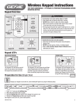
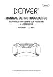
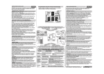
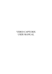
Page 1 of 8
WATER PUMP REPAIR ON AUTOMATIC TRANSMISSION MODELS
Mark 10,10A,15,15A,28,28A, and Merc 100,150,200,250
Introduction
The water pump is located in the driveshaft housing. It is more time consuming to replace
than others but it can be done –take your time and be patient!
The 'Reader's Digest' version of how to repair the water pump is:
“Changing the impeller really is not that hard to do. First remove the powerhead. Remove
the cover to the shift pawls. Remove the lower unit. Remove the cotter pin on the shift lever.
Now rotate the shift lever (at the transmission) so that the hole is at the top. You can now
push on the drive shaft to remove the wrap spring transmission. Use a piece of 1/4” flat bar
about 7” long and 1-3/8” wide to remove bearing locknut (left hand thread). Pull the bearing
and then the impeller.” (Posted by Sparky).
This paper provides info on making the tools and repairing the water pump. It is to be used
along with the Mercury Service Manual.
A copy of the Mercury Service Manual and a Parts List can be purchased at
www.oldmercs.com, e-Bay, etc. Parts Lists are also online at:
http://www.wnyaomci.wizardoutboardforum.com/manual.html and
http://www.mercruiserparts.com/. Another option is to purchase a seal kit from
http://www.vintageoutboard.com, which includes the repair instructions.
Manuals/Tools/Parts also available at: http://www.johnsmcintosh.com/Tools.htm
Follow the manual carefully when working on a motor.
Early models - i.e. Mark 10,10A,15,15A,28, and Mark 28A (below s/n 1236090) the water
pump cartridge has to be pulled out to change the impeller.
Later models - Mark 28A (s/n 1236090 & up) and Merc models have the water pump
cartridge reversed – “for easier disassembly”. The impeller can be changed without
removing the water pump cartridge or the powerhead.
The Service Manual describes the repair of both types together - which is confusing.
Mercury really did not write this procedure very well.
Disassembly
1) Shift motor to forward.
2) Remove transmission cover plate. Be careful - the pawl springs behind the cover plate
may pop out. Remove pawl springs, shaft and spacer.
3) Remove lower unit.
4) Remove cotter pin from lower control shift rod and turn transmission shaft lever up – or
pull the pawls outward to clear the neutral and forward/reverse springs.
AGF 04/03/10
Page 2 of 8
WATER PUMP REPAIR ON AUTOMATIC TRANSMISSION MODELS
Mark 10,10A,15,15A,28,28A, and Merc 100,150,200,250
5) Remove powerhead. On Mark 10,10A, and 15A, the shift linkage must be disconnected
and removed with the powerhead. Later style models Mark 28A (s/n 1236090 and up),
and Merc models, can be serviced without removing the powerhead. I recommend
removing it to make it easier to work on.
6) Push down on driveshaft to remove entire driveshaft/transmission assembly. On later
models (powerhead installed) a long 10-32 screw can be used to pull out the
transmission assembly and then the driveshaft as described in the manual.
7) Disassemble the transmission, if necessary. Note location of bronze thrust washers.
Lower thrust washer is .020” thick, upper washer is .020” or .031” on some models.
8) Working on driveshaft housing, use Ball Bearing Lock Ring Tool to remove ball bearing
lock ring. Turn tool clockwise to loosen – left hand thread.
9) Ball Bearing Lock Ring Tool – Options
A) See Pic01 & Pic02-Ball Bearing Lock Ring Tool. Weld two bars 3/8”x1/4”x1” to a pipe.
The bars extend 3/8” from the pipe, pipe is 3/4”nominal size. Critical dimensions are
the 3/8” bar width and 1-1/4” distance across the bars. The pipe/bar assy. can be
squeezed in a vise to get the 1-1/4” distance. Overall pipe length is 15” & pipe is
drilled for a 3/8” dia. crossbar handle. Basically, we made it from scrap material.
Note the 1-1/4” distance across the bars gives a loose fit. Dimension can be
increased to 1-3/8” if the ends are radiused to fit lock ring.
Pic01-Ball Bearing Lock Ring Tool
AGF 04/03/10
Page 3 of 8
WATER PUMP REPAIR ON AUTOMATIC TRANSMISSION MODELS
Mark 10,10A,15,15A,28,28A, and Merc 100,150,200,250
Pic02-Ball Bearing Lock Ring Tool
B) Modify a 3/8” universal joint. Disassemble a 3/8” universal joint. Cut a 3/8” square bar
to a length of 1-1/4” (see note above). Center the bar in the prongs of the u-joint, drill,
& re-install the pin.
C) Obtain a pipe or tubing having approx. 1-1/4” to 1.375” O.D.. Cut it to leave two tabs
3/8” wide x 3/8” deep.
D) Modify a deep socket by cutting tabs to fit the lock ring.
E) Use a piece of 1/4” flat bar about 7” long and 1-3/8” wide.
F) Use a 3/8” square bar. Cut notches in a piece of pipe and weld or glue a 3/8” square
bar by 1-1/4” long in the end.
AGF 04/03/10
Page 4 of 8
WATER PUMP REPAIR ON AUTOMATIC TRANSMISSION MODELS
Mark 10,10A,15,15A,28,28A, and Merc 100,150,200,250
G) Early Models - pull out impeller, water pump cartridge assembly and driveshaft
bearing using water pump puller tool. Make sure the tool is pulling on the impeller not
the driveshaft housing above it. Manual says cover plate (large washer) cannot be
removed without tilting it. Not true – it will pull out with the impeller – just bent but
easily flattened.
H) Later Models - pull out impeller, impeller plate, sealing cover, ‘L’ washer and ball
bearing. Pull on the impeller not the water pump cartridge above it.
10) Water Pump Puller Tool – Options
A) Mercury still sells this tool. I made one from heavy wire, generally bent to the shape
shown in the manual. The wire was too thin - but it did work. I made another from wire
approx. 3/16” dia., see Pic03- Puller Tool. The 'bent' ends have to be small enough to
fit thru the water pump, as shown in the manual. The cartridge can be hard to pull out
on the earlier models… I sometimes put a 2x4 thru the handle as a crossbar to pull on
it.
Pic03-Puller Tool
AGF 04/03/10
Page 5 of 8
WATER PUMP REPAIR ON AUTOMATIC TRANSMISSION MODELS
Mark 10,10A,15,15A,28,28A, and Merc 100,150,200,250
11) Water Pump Puller Tool – Options (cont'd)
B) I now use a small slide hammer with 2 expandable hooks, see Pic04-Slide HammerPuller. The hooks expand and do not slip off. A couple of tugs and it is out! Wish I'd
known that before, it would have eliminated a lot of the contortions I went thru trying to
pull these things out!
(Source: http://www.harborfreight.com/cpi/ctaf/displayitem.taf?Itemnumber=5469 ).
Pic04-Slide Hammer-Puller
C) Or Push out from the top.
Early models - use a round bar (or deep socket and extension) with a dia. of 0.675”
(max.) to fit thru the hole in the driveshaft housing and push on the impeller. Hit the
bar with a hammer to push out the impeller and water pump cartridge.
Later models - Mark 28A (s/n 1236090 & up), and Merc models - only the impeller,
cover, and bearing are pulled out. The service manual does not describe how to
remove the water pump cartridge. Oldmercs.com states: “Unnecessary removal of
this housing is not recommended.”
If removing it – use a puller or drive it out from the top using a large wooden dowel.
11) Clean and inspect all parts for wear. If impeller vanes are broken off – make sure all
pieces are removed and water passages are clear.
AGF 04/03/10
Page 6 of 8
WATER PUMP REPAIR ON AUTOMATIC TRANSMISSION MODELS
Mark 10,10A,15,15A,28,28A, and Merc 100,150,200,250
Reassembly
1) Replace all seals and gaskets.
2) Manual shows a Water Pump Assembler Shaft Tool. The motor can be assembled
without this - it was a 'later addition'. It's basically a dummy shaft made to fit the Ball
Bearing Lock Ring Tool. I use the driveshaft as an assembly tool.
3) Tilt driveshaft housing up for reassembly. Another way is to install the housing upside
down on a motor stand or to a 2x6 clamped in a vise. The housing can be tilted into the
best position. Pic05-Housing Inverted.
Pic05-Housing Inverted
AGF 04/03/10
Page 7 of 8
WATER PUMP REPAIR ON AUTOMATIC TRANSMISSION MODELS
Mark 10,10A,15,15A,28,28A, and Merc 100,150,200,250
4) Early models – install cover plate in housing below locating pin. Slide ball bearing, water
pump cartridge with sealing ring and “L” washer installed, and impeller onto the
driveshaft . Install driveshaft into housing being careful to align cartridge groove with the
dowel pin in housing. Pull on driveshaft to seat cartridge and bearing in place. Push out
driveshaft. Then install the ball bearing lock ring and tighten (turn counterclockwise –
left hand thread).
Later models – slide ball bearing, “L” washer, sealing cover with rubber ring installed,
impeller plate and impeller onto the driveshaft. Lubricate impeller with liquid soap or
light grease. Install drive shaft into housing. Rotate driveshaft (clockwise at splined end)
while pulling to seat impeller and bearing in place. Push out driveshaft. Then install the
ball bearing lock ring and tighten (turn counterclockwise – left hand thread).
5) Checking End Play
A) Using Transmission Gauge
Measure end play as described in the manual.
B) Dial Indicator
Install driveshaft and transmission without the neutral and forward/reverse springs.
Bolt on lower unit. Measure the end play at the driveshaft end with a dial indicator.
C) End Play Stop Bar
Make a stop bar as shown in Pic06-End Play Stop Bar. This is a flat bar with two
holes to bolt bar to driveshaft housing and a bolt centered above the driveshaft. Install
driveshaft and transmission without the neutral and forward/reverse springs. Bolt on
lower unit. Measure gap between bolt and driveshaft with dial caliper or feeler gauge.
Pull up on driveshaft and measure clearance. The difference is the endplay.
Pic06-End Play Stop Bar
AGF 04/03/10
Page 8 of 8
WATER PUMP REPAIR ON AUTOMATIC TRANSMISSION MODELS
Mark 10,10A,15,15A,28,28A, and Merc 100,150,200,250
6) Install the neutral and forward/reverse springs on transmission assembly. Turn
driveshaft counterclockwise and push into neutral spring.
7) Check impeller key is on driveshaft.
8) Insert driveshaft into driveshaft housing. Turn driveshaft clockwise (from the splined
end) until impeller and key align. Push assembly in all the way. The driveshaft and
transmission can also be installed separately as per the manual.
9) Check impeller key is in properly by turning driveshaft clockwise. The shaft should be
difficult to turn by hand.
10) Install gear housing.
11) Install flinger ring and o-ring on driveshaft.
12) Install powerhead.
13) With motor in neutral and transmission shift lever horizontal – adjust the lower control
rod ‘till it fits into shift lever. Install cotter pin.
14) Install pawl springs as per the manual.
15) Hold the pawl springs in place with a thin putty knife or shim stock. Loosely bolt on the
cover and gasket then pull out the putty knife or shim stock.
16) Fill with Lubriplate 105 grease or equivalent.
17) Check telltale or “pee” hole is not plugged.
18) Start motor in water and check for water from telltale. Note when running in a test tank,
water level should be above the lower dynafloat mounts to prime the water pump.
19) That’s it – tune it up and run it!
I hope this has been helpful, any comments or questions are welcome.
Allan Fuller ([email protected])
Acknowledgements
I have shamelessly plagiarized the Merc Service Manual. Some of the info was obtained
from posts on John’s Old Mercury Q&A Board.
Rev01 04/03/10 – Pics added.
AGF 04/03/10