1
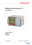
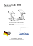
Operating Manuel Worm Gear Screw Jack M0-5 / J1-5 Model N/V/R M0-5 / J1-5 Worm Gear Screw Jack Contents 1 Important Information....................................................................... 2 1.1 Instructions on Documentation ........................................................ 2 1.2 Safekeeping of the Documentation .................................................. 2 1.3 Used Symbols .................................................................................... 2 1.4 Qualified Staff ................................................................................... 2 1.5 General Safety Instructions ............................................................... 3 2 Overview of the Worm Gear Screw Jacks............................................ 4 3 Design of the Worm Gear Screw Jack ................................................. 5 4 Assembly........................................................................................... 6 4.1 General Assembly Instructions ......................................................... 6 4.2 Mounting Several Worm Gear Screw Jacks in Parallel ..................... 7 5 Commissioning .................................................................................. 8 6 Maintenance ..................................................................................... 8 6.1 Lubricants and Fill Quantities............................................................ 9 7 Malfunctions ................................................................................... 10 8 Manufacturer’s Declaration ............................................................. 11 1 M0-5 / J1-5 Worm Gear Screw Jack 1 Important Information This chapter contains important information on the safe handling of the product and on this operating manual. 1.1 Instructions on Documentation The following instructions will guide you through the entire documentation. We assume no liability for damages resulting from non-compliance with this operating manual. Forward this operating manual to the plant operator so that it is available if needed. 1.2 Safekeeping of the Documentation Keep this operating manual and all other applicable documents safe so that they are available if needed. 1.3 1.4 Used Symbols Information Instructions and information on the operation of the worm gear screw jacks. Attention! Non-compliance may result in material damage and impair the operation of the gear unit. Warning! Safety instruction: non-compliance may result in serious or fatal injuries. QR Barcode Provides a direct link to the products on our website. Compatible with QR barcode scanner apps for all Android, Apple and Windows smart phones / tablets. Qualified Staff Qualified staff according to this operating manual refers to specialists who are familiar with the installation, assembly, commissioning and operation of the worm gear screw jacks and the hazards involved and who possess the necessary capabilities on the basis of their specialist training and knowledge of the applicable standards. 2 M0-5 / J1-5 Worm Gear Screw Jack 1.5 General Safety Instructions The following warnings, preventive measures and instructions are intended to guarantee your safety and to avoid damage to the lifting gear or the components connected to it. This chapter contains warnings and instructions that generally apply to the handling of the lifting gear. Intended Use: The M0-5 / J1-5 worm gear screw jacks are intended only to carry out lifting, lowering, tilting and feeding motions. Please find lifting capacities in our catalog or atwww.neff-gewindetriebe.de. Any other use is considered misuse. The manufacturer assumes no liability for any damage resulting from misuse. If the device is installed in machines or plants, commissioning is prohibited until it is determined that it complies with the EC machinery directive. Attention! Requirement according to the German accident prevention regulations VBG14 / VBG 70: If worm gear screw jacks are operated in theatre stages (VBG 70), lifting platforms (VBG 14) or lifting equipment where there is a danger to persons, we generally recommend using a safety nut for fall protection. Attention! This operating manual must be kept close to the device and be easily accessible and available to all users. Attention! Risk of damage to the lifting gear resulting from storage and transport. Correct storage, installation and assembly as well as diligent operation and maintenance are prerequisites for the trouble-free and safe operation of the worm gear screw jacks. The worm gear screw jack must be protected against mechanical impacts and vibrations during transport and storage. Warning! Work on live components: E.g. installation of limit switches or a drive unit must only be carried out by trained electricians. 3 M0-5 / J1-5 Worm Gear Screw Jack 2 Overview of the Worm Gear Screw Jacks Description of a Worm Gear Screw Jack: Neff worm gear screw jacks are used for applications where precise lifting, lowering, tilting and feeding motions are required. Our standard range comprises 11 models (Multi 0-5 / Jumbo 15). The cubic housing that is machined on 4 sides allows for the installation of motors, gears or pressure transducers. All models are designed to cater for pressure and tensile loads as well as position-independent operation. Basically, 2 different movement principles have to be distinguished: TGS-N standard model TGS trapezoidal screw TGS-V protected against distortion Axially moving screw KGS-N standard model KGS ball screw KGS-V protected against distortion TGS trapezoidal screw TGS-R rotating screw KGS ball screw KGS-R rotating screw Rotating screw 4 M0-5 / J1-5 Worm Gear Screw Jack 3 Design of the Worm Gear Screw Jack SHG-TGS-N model (standard) Position Designation 1 2 3 4 5 6 7 8 9 10 11 12 13 14 15 16 17 Housing Worm gear Bering cover Axial grooved ball bearing Worm gear shaft Grooved ball bearing or taper roller bearing Snap ring acc. to DIN 471 Radial shaft seal ring acc. to DIN 3760 Grub screw Lubrication nipple Trapezoidal screw Cover tube Cover tube end cap Sliding bearing Fitted key acc. to DIN 6885 Mounting plate Grub screw for mounting plate 5 M0-5 / J1-5 Worm Gear Screw Jack 4 4.1 Assembly General Assembly Instructions The worm gear screw jack is fastened via the housing or other fastening components (mounting plates or cardan adapters, see QR code below). The housing always needs to be screwed to a machined surface (not to rolled steel profiles or similar) in order to avoid misalignment or noise. Depending on the respective application, the worm gear screw jack and the screw have to be precisely aligned at a right angle or in parallel to the machine component and tightened during assembly. The tolerances of the four assembly sides correspond to the DIN ISO 2768-mH standard. Size Bolts (min. 8.8) M0 M1 M2 M3 M4 M5 J1 J2 J3 J4 J5 M6 M8 M8 M10 M12 M20 M24 M30 M30 M36 M42 Length of engagement Max. torque in Nm 12 13 15 15 16 30 40 45 45 54 80 10 25 25 50 80 400 730 1450 1450 2600 4000 The torques mentioned in the table are only rough and nonbinding guidelines – see VDI 2230. Lateral forces have to be absorbed by suitable guiderails; otherwise the device lifecycle would be shortened. Attention! The lubrication nipples must always be accessible during operation. Attention! Do not hammer the shaft end or the screw when aligning the worm gear screw jack. QR barcode to Neff fastenings: QR barcode to Neff attachments: 6 M0-5 / J1-5 Worm Gear Screw Jack 4.2 Mounting Several Worm Gear Screw Jacks in Parallel Requirement: One worm gear screw jack is already installed and fastened as described in chapter 4. 1. Bring the second worm gear screw jack into the planned position, but do not fasten it yet. 2. If rotating screws are used, bring the travelling nuts into the same position. 3. Push the coupling or drive shaft onto the worm gear shaft of the worm gear screw jack that is already fastened. 4. Push the coupling or drive shaft onto the worm gear shaft of the second worm gear screw jack. 5. Fasten the worm gear screw jack. 6. Repeat steps 1-5 with any other gear units. Attention! Check the sense of rotation of all lifting elements before assembly. Attention! Use torsionally flexible couplings, drive shafts or cardan shafts in order to compensate for any misalignment of the worm gear screw jackets. Attention! Observe the lubricating film and screw temperature during run-in. If the screw quickly runs dry (or if there are loud running noises with ball screws) and if the temperature is increased despite observing duty time and permissible power, this indicates impermissible lateral forces. QR barcode to Neff couplings: QR barcode to Neff drive shafts: 7 M0-5 / J1-5 Worm Gear Screw Jack 5 Commissioning Attention! Check the operation of the limit switch. If possible, start the worm gear screw jack without any load and increase the load slowly. During commissioning, continuously check the operating temperature, power consumption of the motor and the screw contact pattern. 6 Maintenance With trapezoidal screws, regularly lubricate the screw. With ball screws, observe the following guideline: lubricate approx. every 200 hours with 1ml per 10mm of screw diameter Approx. 5 operating hours after commissioning: Retighten all attachment bolts. After approx. 50-100 operating hours: Lubricate the gear at the lubrication nipples once again. After approx. 200 operating hours or 1 year (sooner in tough operating conditions): Check the screw nut for signs of wear and tear. Clean the screw of old grease and relubricate. After approx. 1000 operating hours or 5 years: Disassemble gear, clean it of old grease and relubricate: 1. 2. 3. 4. 5. 6. 7. 8. Remove the two grub screws at the bearing cover Take the screw out (remove screw protection if required). Unscrew the bearing cover. Remove the old grease. Refill with new grease. Strongly press the bearing cover down (10 times the normal contact force). Loosen the bearing cover again. Put the bearing cover into place and fasten it with two grub screws. Attention! When assembling the bearing cover, make sure it fits smoothly and that there is no axial play. Attention! Change the screw nut if the axial play exceeds 1/4 of the thread pitch (trapezoidal thread). 8 M0-5 / J1-5 Worm Gear Screw Jack 6.1 Lubricants and Fill Quantities Types of factory grease: Worm gear screw jacks / trapezoidal screws: Aral Aralub MKL 2 Aral safety data sheet: Ball screws: Interflon Fin Grease MP 2/3 Interflon safety data sheet: Fill quantities: Type Fill quantities in grams M0 M1 M2 M3 M4 M5 J1 J2 J3 J4 J5 15 45 65 120 420 900 1200 1200 1200 2500 5000 In addition to our factory lubricants, other equivalent brand lubricants may also be used. This only applies if they are compared to the data sheets of the above manufacturers. To much grease increases friction and therefore causes an increase in temperature. There is a sufficient amount of lubricant when a small amount of grease begins to exit at the sealing lips. 9 M0-5 / J1-5 Worm Gear Screw Jack 7 Malfunctions Service: Should malfunctions occur during operation, first try to identify the manner of the malfunction with the table below and to repair it. If it is a malfunction you can not repair, please contact our technical service (see last page). Malfunction Unusual, constant running noises. Unusual, irregular running noises. Unusually high temperature at the housing. Grease or oil exists at the shaft seal ring. Grease or oil exists at the shaft seal ring and at the screw. Trapezoidal screw quickly runs dry. The worm gear shaft does not turn or the screw turns but does not move although the worm gear shaft is turned. Cause Rolling / grinding: Bearing damage Tapping: Irregularity in gearing Foreign object in the grease. Not enough grease. Defective gearing or bearing. Defective sealing. Too much grease in the gear. Assembly fault: Impermissible lateral forces. The connection between the shaft and the hub or the gearing is broken. Remedy Check grease fill level. Consult the technical service. Check grease fill level. Stop drive. Consult the technical service. Check and correct grease filling. Consult the technical service. Consult the technical service. Check and correct grease fill level. Consult the technical service. Repair assembly fault. Consult the technical service. Have the gear repaired. 10 M0-5 / J1-5 Worm Gear Screw Jack 8 Manufacturer’s Declaration We hereby declare that the following product: Worm gear screw jack, version M and J with trapezoidal screws or ball screws model N, R or V in the sizes M0 – M5, J1 – J5 for lifting and lowering loads was manufactured in accordance with the EC machinery directive 2006/42/EC annex II B on incomplete machinery. This incomplete machinery must not be commissioned until the machine it is to be incorporated in has been declared to comply with the provisions of the EC machinery directive, the harmonized standards, European standards or the applicable national standards. The manufacturer undertakes to forward the documentation on the incomplete machinery to national authorities on request. The technical documentation was created according to annex VII B. Person responsible for documentation: Sandro Garofano, QA manager Address of the person responsible for documentation: Neff Gewindetriebe GmbH Karl-Benz-Str. 24 71093 Weil im Schönbuch Germany The following harmonized standards have been applied: DIN EN ISO 12100-1 Safety of machinery – Basic concepts, general principles for design, part 1: Basic terminology, methodology DIN EN ISO 12100-2 Safety of machinery – Basic concepts, general principles for design, part 2: Technical principles and specifications The following national standards, guidelines and specifications have been applied: BGV D8 Accident prevention regulations for hoist gears, lifting and towing equipment Neff Gewindetriebe GmbH Karl-Benz-Str. 24 71093 Weil im Schönbuch Germany +49(0)7157/53890-0 Weil im Schönbuch, 29 August 2012 Hartmut Wandel, Director 11