1
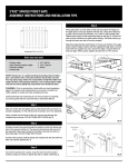
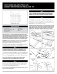
Driven By Customers …
Powered by Proven Products
Table of Contents
Section I – General
Warnings – General Safety
Foreword
Product Description
Tools Required
1.01
1.02
1.03
1.04
Section II – Setup and Installation
When Your Shipment Arrives
Sequence of Installation
Conveyor Orientation
Aluminum Exact Width Stands
Angle Braces
Aluminum Cross Ties
Casters
Steel Telescoping Stands
Steel Cross Ties
Steel Stands with Stabilizers
Universal Side Mounts
Bottom Mounts
Rod Clamp Mounts
Fixed Side Rails
Adjustable Guides
Indented Guides
2.01
2.02
2.03
2.04
2.05
2.06
2.07
2.08
2.09
2.10
2.11
2.12
2.13
2.14
2.15
2.16
Section III – Maintenance
Maintenance Foreword
Belt Tracking
Replacing the Motor Pulley
Belt Change
Adding Tension
Belt Care
Bearing Replacement
Conveyor Exploded View and Parts List
Recommended Spare Parts
Troubleshooting
3.01
3.02
3.03
3.04
3.05
3.06
3.07
3.08
3.09
3.10
Section IV – Warranty and Return Policy
Conveyor Serial Number
Conveyor Warranty, Lost or Damaged Goods
Returns, Order Cancellation/Revision Policy
4.01
4.02
4.03
Installation,
Maintenance,
and Parts Manual
InnerDrive Conveyors
QC Industries LLC
4057 Clough Woods Dr.
Batavia, OH 45103
(513) 753-6000
Fax: (513) 753-6001
www.qcindustries.com
1.01 Warnings – General Safety
Observe safe practices when setting up and operating your QC Industries conveyor.
Climbing, sitting, walking, or riding on conveyor can cause severe injury. Keep off conveyors.
Do not operate conveyors in an explosive environment.
Exposed moving parts can cause severe injury. Lock out power before removing guards.
QC Industries cannot control the installation and/or application of conveyors. Taking protective measures is the
responsibility of the user. When conveyors are used in conjunction with other equipment, or as part of a multiple
conveyor system, check for potential pinch points and/or other mechanical hazards before system start-up.
During normal operation, please make sure that all guards are in place and securely attached to conveyor.
Loosening stand height or angle adjustment screws can cause conveyor sections to drop down unexpectedly,
causing severe injury. Support conveyor sections prior to loosening stand height or angle adjustment screws.
Injury is possible if the stands are not lagged to the floor, cross ties are not used, or angle braces are not present.
Never place a conveyor in operation until all proper mounts are installed and secured. It is the end user’s
responsibility to ensure that the support system is safe and secure.
Never operate equipment unless all operating instructions are understood and all guards, interlocks, covers, safety
devices or circuits and protective components are functioning properly.
Never operate or service this equipment if under the influence of alcohol, drugs or other substances or conditions
which decrease alertness or judgment.
QC Industries InnerDrive Installation, Maintenance, and Parts Manual
1.02 Foreword
Congratulations on purchasing a conveyor from QC Industries, LLC, the leader in low profile conveyors! QC
Industries offers the finest low profile conveyors available, using the highest quality materials and state of the art
manufacturing processes. QC Industries conveyors boast a number of innovative engineering features to assure
you hassle-free setup, smooth operation, and years of continued low-maintenance use. We are proud of our quality
products and are committed to providing you dependable service!
Check your shipment
Before opening the shipment, visually inspect the outside of the crate/box for shipping damage. Carefully unpack
the crate/box, inspecting for component damage which may have occurred inside the packing materials. Contact
the carrier and QC Industries regarding any damage that may have occurred during shipment. Check the contents
of your shipment against the supplied packing slip and inform QC Industries of any discrepancies.
Please read this manual
Inside this manual you will find instructions on how to set up and maintain your QC Industries conveyor properly, as
well as maximize its performance. Please take the time to read this manual and familiarize yourself with these
setup and maintenance instructions. These instructions will help assure a long product life that requires a
minimum amount of service, and keeps your conveyor working at its maximum capacity.
If you need assistance
If you need assistance with your QC Industries conveyor, our highly trained support staff is only a phone call away.
QC Industries welcomes the opportunity to assist you. You can contact the Customer Service department Monday
through Friday, 8am-5pm EST at (513) 753-6000. In addition, your local distributor can provide support in many
ways. Our distributors have been trained at the factory and can be dispatched to your facility to help. You can also
visit our website for additional information and technical documents: www.qcindustries.com
QC Industries InnerDrive Installation, Maintenance, and Parts Manual
1.03 Product Description
The InnerDrive Conveyor has many typical conveyor components. Below is a description of the basic parts and
options for the InnerDrive Conveyor (Figure 1).
6
2
5
3
1
4
10
7
8
9
Figure 1
Typical Components
1.
2.
3.
4.
5.
6.
Conveyor
Sides & Guide Accessories
Standard Mounts
Support Stands
Idler End
Motor Pulley End
QC Industries InnerDrive Installation, Maintenance, and Parts Manual
7.
8.
9.
10.
Angle Brace
Cross Ties
Leveling Foot
Control Box
1.04 Tools Required
Set of Standard Allen Wrenches:
3/32”, 7/64”, 1/8”, 3/16”, 5/32”, 1/4”
Large Adjustable Wrench
A Bubble Level for frame alignment
Set of Metric Allen Wrenches:
2.5mm, 3mm
Wide Flat Head Screw Driver
OR Tail Turning Tool* in Socket Wrench
QC Industries
Part Number
TK-TAILTURN
Screw Gun with T25 Torx bit
Aluminum and Steel Cutting Hack Saw or
equivalent
Wrenches: 1/4”, 7/16”, 9/16”, 3/4”
Tape Measure
* The Tail Turning Tool is QC Industries part number TK-TAILTURN.
Please contact QC Industries Customer Service at (513) 753-6000 to purchase.
QC Industries InnerDrive Installation, Maintenance, and Parts Manual
2.01 When Your Shipment Arrives
n Check your shipment for damage
a. If you have not already done so, visually inspect the outside of the crate or boxes for shipping
damage.
b. Carefully unpack the crate or box, inspecting the components for damage which may have occurred
inside the packing materials.
c. Contact the carrier and QC Industries regarding any damage that may have occurred during
shipment.
d. Check the contents of the shipment against the included packing slip and notify QC Industries of
any discrepancies.
o Locate the items from your order
a. Each conveyor will ship in its own custom built box.
b. Steel Telescoping Stands and Aluminum Multiple Conveyor Stands will ship in individual boxes.
Aluminum Exact Width Stands ship two to a box.
c. Casters are included in a separate box from the conveyor.
d. Cross Ties will ship in a custom built box; the mounting hardware will ship in a bag in a separate box
from the conveyor.
e. Mounts are packaged in a separate box from the conveyor.
f. Sides and Guiderails will ship in the conveyor’s box, with the exception of 24” wide conveyors whose
boxes are too wide to also accommodate sides; in this case the Siderails or Guiderails will ship in a
custom built box. Clamps to hold the siderail to the conveyor will be attached to the conveyor at the
factory; mounting brackets for guides and hardware will ship in a separate plastic bag in a box
separate from the conveyor.
p Record the Conveyor’s Serial Number
a. The conveyor’s serial number is located on the frame at the drive end of the conveyor, opposite the
side on which the motor lead wire and control card will be mounted.
b. Record the serial number in a place where it can be accessed for reference; a place has been
provided on the back cover that can be used for multiple conveyors. This will assist any future inquires
regarding the conveyor, its accessories, the order it was shipped on, or replacement parts.
c. Proceed to Section 2.02 for the Sequence of Installation.
QC Industries InnerDrive Installation, Maintenance, and Parts Manual
2.02 Conveyor Orientation
To set up the conveyor after receiving your shipment, QC Industries recommends following these
steps. Please refer to their respective sections for more detailed instructions.
n Move the Conveyor and Accessories into
location
Using appropriate equipment and safe moving methods, move
the conveyor and accessories to the desired assembly, staging,
or installation area (Figure 1). Set the conveyor in the correct
operating orientation with regard to the drive position and belt
direction.
See Section 2.03 for detailed instructions
Figure 1
o Mount the Conveyor to its Stands and Cross Ties or
Mounts
Use QC Industries stands and mounts (or any compatible stands and
hardware) to mount the conveyor in the desired location (Figure 2). Make
sure the conveyor mounted on stands is on a flat, level surface. QC
Industries recommends that stands with leveling feet are anchored to the
floor.
See Sections 2.04 – 2.13 for detailed instructions
Figure 2
p Install the Sides or Guides
It is recommended that Side and Guide Rail Assemblies are next in the
sequence (Figure 3).
See Sections 2.14 – 2.16 for detailed instructions
Figure 3
QC Industries InnerDrive Installation, Maintenance, and Parts Manual
2.03 Conveyors 12’ Long and Under
n Orient the Conveyor based on the Drive Location
a. Set the conveyor in its operating position, taking care to note where the drive will be located.
InnerDrive Conveyors can be built with the drive pulling; with a left hand drive or right hand drive (left
hand and right hand are defined as if you are standing at the drive end of the conveyor).
The 14th digit in the conveyor’s part number will indicate the orientation and direction, as shown in the
following example of a 12” wide x 10’ long conveyor:
1MSCH12-120-AABA-MAA
There are two positions available (Figure 1):
A
Left Hand, Drive Pulling
B
Right Hand, Drive Pulling
A
A
B
B
Figure 1
b. Position the conveyor for operation, taking care to note
that access is needed for the tail idler’s 1/4-28 Button
Head Socket Screw (Figure 2) when other equipment is
nearby. This is important when tensioning the belt from the
tail end.
1/4 - 28
Button Head
Socket Screw
o Install Stands, Mounts, Sides, and Guides
Figure 2
a. Proceed to Sections 2.04 – 2.13 for instructions on installing Stands and Mounts.
b. Proceed to Sections 2.14 – 2.16 for instructions on installing Sides or Guides.
QC Industries InnerDrive Installation, Maintenance, and Parts Manual
2.04 Aluminum Exact Width Stands
Aluminum Exact Width Stands can be located anywhere along the length of the frame, as they mount
directly to the conveyor’s accessory holes in the frame. Ideally, the stands should be placed as far
apart as possible for maximum stability.
The stand at the Tail End of the conveyor normally has no obstructions and can be placed as close to
the end as needed.
n Prepare the Stand for Installation
a. For shipment, the stands will have their mounting bracket slid
down the extrusion. Use a 1/2” Wrench to loosen the Hex Head
Screws holding the Brackets and move them up to engage the
conveyor frame, approximately 1 1/2” (or more for cleated belts)
(Figure 1).
b. If the stands are to be
used with Aluminum Cross
Ties, it is advised to attach
the Gusset Plates prior to
mounting
the
conveyor
(Figure 2). Refer to Section
2.06 on Aluminum Cross Ties
for specific instructions.
Operating
Position
Shipping
Position
Figure 1
Cross Tie
Gusset Plate
Figure 2
o Install the Stand
a. Locate the bag of 10-32 x 7/8” long Torx Head Thread Forming
Screws from one of the boxes with the shipment. There are four per
stand.
b. Line up the stand with the accessory holes in the side of the
conveyor frame and use a Screw Gun with a Torx bit to fasten the
stand to the frame (Figure 3).
Figure 3
QC Industries InnerDrive Installation, Maintenance, and Parts Manual
2.04 Aluminum Exact Width Stands (continued)
p Adjust the Height using the Leveling Feet
Hex Nut
The Leveling Feet on all of QC Industries Stands are designed to
allow fine adjustment and so they can be lagged to the floor. Note:
if it is not feasible to permanently attach the stands to the floor or
the conveyor is to be made mobile with casters, then Cross Ties or
Angle Braces must be used.
To adjust the stand height with the Leveling Feet:
a. Use a large adjustable wrench to loosen the Hex Nut
Lag to
floor here
Welded Hex
Figure 4
b. Rotate the hex welded to the foot to the desired height (Figure 4).
c. Retighten the Hex Nut to secure it in position.
Injury is possible if the stands are not lagged to the floor, cross
ties are not used, or angle braces are not present. Never place
a conveyor in operation until all proper mounts are installed
and secured.
d. Frame alignment is one of the key items that assure the belt properly tracks during startup. Make
sure the conveyor frame has no twist by using a bubble level and checking measurements from the
mounting surface.
e. Proceed to Section 2.05 for instructions on installing Angle Braces.
f. Proceed to Section 2.06 for instructions on installing Aluminum Cross Ties.
g. Proceed to Sections 2.14 – 2.16 for instructions on installing Sides and Guides.
QC Industries InnerDrive Installation, Maintenance, and Parts Manual
2.05 Angle Braces
When it is not feasible to bolt the Aluminum Exact Width Stands to
the floor, they can be stabilized by use of Angle Braces. Angle
Braces will only work for conveyors mounted horizontally. If your
conveyor is mounted at an incline, Cross Ties must be used
instead. Also, Angle Braces will only work with stands that are 18”
or taller (i.e. part number 0182-18-21-WW).
Angle Braces are shipped as a set, with one Right Hand Brace and
one Left Hand Brace, with four Torx Head Screws, and four screw
sets (Hex Head Screw, Flat Washer, and Square Nut).
Square Nut
Before installing Angle Braces, the Aluminum Exact Width Stands
should already be assembled to the conveyor.
n Install the Angle Braces to Exact Width Stands
a. Start by inserting the square nuts in the stand leg’s channel at
the base where the channel has been routered (Figure 1).
Figure 1
b. Place the Angle Brace over the Square Nuts, and insert the Hex Screws and Washers into Square
Nuts (but do not fully tighten them). There are four holes provided, but only two of them will be used.
c. Using a Screw Gun with a Torx bit, drive the
Torx Head Screws into the top section of the
Brace (Figure 2). The holes will line up with
accessory holes in the conveyor’s frame.
d. Tighten the Hex Head Screws so the Brace is
secured to the stand, and repeat the installation
for the Brace on the other side.
Torx Head Screw
e. Frame alignment is one of the key items that
assure the belt properly tracks during startup.
Make sure the conveyor frame has no twist by
using a bubble level and checking
measurements from the mounting surface.
f. Proceed to Sections 2.14 – 2.16 for
instructions on installing Sides and Guides.
Figure 2
QC Industries InnerDrive Installation, Maintenance, and Parts Manual
2.06 Aluminum Cross Ties
When it is not feasible to bolt the Aluminum Stands to the floor, the conveyor and stand assembly can
be stabilized by use of Cross Ties.
Cross Ties are sold in standard lengths, and are meant to be cut to length during installation based on
the final placement of the stands.
The Cross Ties can be installed once the conveyor has been secured to the stands.
In one of the boxes of the shipment, there will be a bag containing the Cross Tie Gusset Plates and
fasteners.
n Install the Gusset Plates to Aluminum Stands
a. Insert two Square Nuts into each leg’s channel from the base where the
channel has been routered (Figure 1).
b. The Gusset Plate should be
positioned over the Square Nuts in
the channel and secured with the
Hex Head Screws and Flat Washers
(Figure 2). Although there are eight
holes in the Gusset Plate, only four
of them will be used.
Figure 1
Figure 2
o Install the Cross Tie Extrusions
a. Measure the distance between the
stands and cut the Cross Tie Extrusion
to fit with a saw blade that is
appropriate for Aluminum (Figure 3).
b. The Gusset Plates can mount to the
inside or outside of the stand’s leg, or
to the stand’s Cross Member if there is
no room on the leg (note: this will
require disassembly of the stand to do
so).
CutCross
Cross Tie
Tie to
Cut
tolength
length
Figure 3
c. Proceed to Sections 2.14 – 2.16 for instructions on installing Sides and Guides.
QC Industries InnerDrive Installation, Maintenance, and Parts Manual
2.07 Casters
QC Industries offers swivel locking casters to replace the stands’ leveling feet for applications when
conveyors need to be moveable.
Casters will ship in a separate box from the stands.
n Install Casters to Aluminum or Steel Stands
a. Remove the Leveling Foot from the stand by loosening the Hex
Nut with a large adjustable wrench. Spin the foot to unthread it from
the stand leg until it is free.
b. Install the Casters by threading the 4 1/2” stem into the base of
the stand where the Leveling Foot was previously. The Caster will
have its own 3/4-10 Hex Nut (Figure 1).
c. Once the conveyor is mounted on the stand, the caster’s stem
can be used for final height adjustment, up to 1 1/2” up or down.
Use a large adjustable wrench to loosen the hex nut, engage the
swivel lock, then rotate the caster to the desired height by hand,
and finally retighten the Hex Nut to secure it in position.
o Secure the System
a. When the conveyor is not being moved or is in operation, the
Caster’s swivel lock should be engaged. It is conveniently located
over the caster’s wheel so it can be engaged and disengaged by
foot.
b. QC Industries requires the use of Cross Ties or Angle Braces if
Casters are used. Note: The width of the system should be no less
Figure 1
than 1/3 of the system’s height (i.e. for a 36” high system, a stand
assembly on casters should be at least 12” wide). When assembling, please make sure the assembly
is stable for your application.
Warning: Moving conveyors with casters can create dynamic
forces that could tip the conveyor. Use caution when moving a
conveyor with casters.
c. Proceed to Sections 2.14 – 2.16 for instructions on installing Sides and Guides.
QC Industries InnerDrive Installation, Maintenance, and Parts Manual
2.08 Steel Telescoping Stands
Steel Telescoping Stands are used when a wide range of adjustment is needed for the stands.
They are available in four widths and four height ranges. The nominal stand width used must be at
least 2” wider than the conveyor that will be mounted on it.
n Adjust the Height of the Stand
a. Adjust the Stand’s height to the desired elevation before mounting the
conveyor. Loosen the Hex Head Screws that secure the channel with a
9/16” Wrench (Figure 1). If Cross Ties are to be used with the stands, it
is recommended to install the Cross Tie Gusset Plates before finishing
the height adjustment. See Section 2.09 for detailed instructions.
b. Slide the stand’s H Section up or down in the channel. Re-tighten the
screws to secure it in position.
Loosen
to adjust
height
If it is necessary to use the stand’s telescoping adjustment once the
conveyor it installed, the conveyor must be supported by some other
means, as the stand will not support any weight during the adjustment.
o Determine the Stand Locations
Figure 1
a. The stand at the drive end and idler end of the conveyor normally have
no obstructions and can be placed as close to the ends as needed. Ideally, the stands should be
placed as far apart as possible for maximum stability.
p Install the Mount
a. Use of Steel Telescoping Stands requires the use of a separate mount, which is not included with
the stand.
b. Instructions for installing mounts to the conveyor and stand are in Sections 2.11 – 2.13.
QC Industries InnerDrive Installation, Maintenance, and Parts Manual
2.08 Steel Telescoping Stands (continued)
q Adjust the Leveling Foot
a. Once the conveyor is mounted on the stand, the Leveling Feet
can be used for final height adjustment, up to 1 1/2” up or down.
b. Use a large adjustable wrench to loosen the Hex Nut, then rotate
the hex welded to the foot to the desired height (Figure 2), and
finally retighten the 3/4-10 Hex Nut to secure it in position.
c. The Leveling Feet on all of QC Industries Stands are designed so
they can be lagged to the floor. If it is not feasible to permanently
attach the stands to the floor or the conveyor is to be made mobile
with casters, then Cross Ties must be used.
Figure 2
Injury is possible if the stands are not lagged to the floor, cross
ties are not used. Never place a conveyor in operation until all
proper mounts are installed and secured.
d. Frame alignment is one of the key items that assure the belt properly tracks during startup. Make
sure the conveyor frame has no twist by using a bubble level and checking measurements from the
mounting surface.
e. Proceed to Sections 2.14 – 2.16 for instructions on installing Sides and Guides.
QC Industries InnerDrive Installation, Maintenance, and Parts Manual
2.09 Steel Cross Ties
When it is not feasible to bolt Steel Stands
to the floor, the conveyor and stand
assembly can be stabilized by use of Cross
Ties.
Cut
to length
length
CutCross
Cross Tie to
Cross Ties are sold in standard lengths, and
are meant to be cut to length during
installation based on the final placement of
the stands.
n Cut the Unistrut to length
Figure 1
Measure the inside distance between the stands and cut the unistrut sections to length with a saw
blade that is appropriate for steel (Figure 1).
o Install the Gusset Plates to the Steel Stand
The Gusset Plates mount through the
holes in the lower leg of the stand
assembly (Figure 2).
a. To install, the H Section of the stand
must first be lifted clear of the mounting
holes (Figure 3).
b. Place a Gusset Plate over the holes in
the Stand Leg’s Base, and insert a 3/816 x 1 1/2” Hex Head Screw with a 3/8”
Flat Washer through the two holes.
Gusset
Plate
Double
Nut Clamp
c. Secure the Gusset Plate by positioning
a Double Nut Clamp in the inside of the
Stand Leg, and threading the Hex Head
Screws into it.
Install in
leg holes
Figure 2
d. The Double Nut Clamp can be used to engage the Stand’s H Section if the Double Nut Clamp
creates an interference with the H Section.
p Install the Cross Tie to the Gusset Plate
a. Position a Double Nut Clamp over the remaining 3/8”
holes in the Gusset Plate, insert Hex Head Screws with
Washers through, and engage them loosely into the Double
Nut Clamp.
b. Slide the Unistrut Cross Tie in behind the Nut Clamp so it
butts up against the Stand Leg, and secure it in place by
tightening the Hex Head Screws.
Stand H
Section
Double
Nut Clamp
c. Proceed to Sections 2.14 – 2.16 for instructions on
installing Sides and Guides.
Figure 3
QC Industries InnerDrive Installation, Maintenance, and Parts Manual
2.10 Steel Stands with Stabilizers
Steel Stands with Stabilizers are used when it is not
possible to support the conveyor with more than
one stand.
1” Screw
They are available in four widths and four height
ranges. The nominal stand width used must be at
least 2” wider than the conveyor that will be
mounted on it.
Washer
Unistrut
n Install the Stabilizers to the Leveling
Feet
a. Rotate the feet so the holes 2” apart are in line
(Figure 1).
b. Slide the Double Nut Clamp into the unistrut
channel.
c. Assemble the feet to the channel with the 3/8-16
x 1” Hex Head Screws and 3/8” Washers from the
top of the foot, into the Double Nut Clamp and
tighten them into position. The fine adjustment
using the leveling feet is not available once the
stabilizers are installed.
Leveling
Foot
Double
Nut
Clamp
Figure 1
o Adjust the Height of the Stand
a. Adjust the Stand’s height to the desired elevation before mounting the
conveyor. Loosen the Hex Head Screws that secure the channel with a
9/16” Wrench (Figure 2).
b. Slide the stand’s H section up or down in the channel. Re-tighten the
screws to secure it in position.
Loosen
to adjust
height
If it is necessary to use the stand’s telescoping adjustment once the
conveyor it installed, the conveyor must be supported by some other
means, as the stand will not support any weight during the adjustment.
p Determine the Stand Location
a. The stand at the drive end and idler end of the conveyor normally have
no obstructions and can be placed as close to the ends as needed.
Ideally, the stands should be placed as far apart as possible for maximum stability.
Figure 1
q Install the Mount
a. Steel Stands require the use of a separate mount. Instructions for installing mounts to the conveyor
and stand are in Sections 2.11 – 2.13.
b. Proceed to Sections 2.14 – 2.16 for instructions on installing Sides and Guides.
QC Industries InnerDrive Installation, Maintenance, and Parts Manual
2.11 Universal Adjustable Side Mounts
The Universal Adjustable Side Mounts are used to support the conveyor above its mounting surface.
There are three versions available: Frame Mounted (125-0181-04), Tee Slot Mounted (125-0181-01),
Multi-Tier Stand Mount (125-0181-05). They are each supplied with fasteners appropriate for the style
of mounting.
If the conveyor has a cleat height of 1”, 2”, or 3” the Universal Raised Side mount is used. It will create
a higher top of belt height from the mounting surface or stand top plate. The Universal Raised Side
Mount is available in three versions as well: Frame Mounted (125-0182-04), Tee Slot Mounted (1250182-01), and Multi-Tier Stand Mounted (125-0182-05).
n Frame Mounted Universal Adjustable Side Mounts
a. For the frame mounted versions, the mount can
be installed on the conveyor anywhere along its
length that there are accessory holes available
(Figure 1).
Mount to Accessory
Holes in Frame
b. The thread-forming 10-32 x 7/8” Torx Head
Screws provided with the Mounts are long enough
to allow accessories to be stacked over one
another (such as a Guide Bracket).
Torx Screws
Figure 1
o Tee Slot Mounted Universal Adjustable Side Mounts
Washer
Hex Nut
a. For the Tee Slot Mounted version (Figure 2),
insert the 1/4-20 Square Nuts in the tee slot,
and thread the 1/4-20 x 1” Set Screws into the
Square Nuts.
b. Locate the Mount over the Set Screws, and
tighten them in place so they dig into the tee
slot.
Mount to
Tee Slot
c. Secure the Mount by placing 1/4” Flat
Washers onto the Set Screws and threading
1/4-20 Hex Nuts onto them.
Figure 2
QC Industries InnerDrive Installation, Maintenance, and Parts Manual
2.11 Universal Adjustable Side Mounts (continued)
p Install the Mount to a Steel Stand
Screw
The Frame Mounted and Tee Slot Mounted versions of the
Side Mount can be secured to the top plate of a Steel
Telescoping Stand.
Washer
a. Using the fasteners provided, insert a 5/16-18 x 3/4”
Hex Head Screw through a 5/16” Flat Washer and into
the slot in the base of the mount (Figure 3).
b. Secure the mount using a second Flat Washer and
5/16-18 Hex Nut from the underside of the stand.
Mount to
Steel Stand
Washer
Hex Nut
Figure 3
p Multi-Tier Stand Mounted Universal Adjustable Side Mounts
Square Nut
Channel
Routered
The Multi-Tier Stand version mounts to the conveyor the same as
the frame mounted version, but comes with Square Nuts and Hex
Head Screws for mounting into the channels of the top extrusion of
the Aluminum Multi Tier Stand, through the two holes in the
mount’s base.
a. To install, insert one 5/16-18 Square Nut into each channel of
the Stand’s Top Extrusion (Figure 4). The channel has been
routered to accommodate the Square Nut.
Figure 4
b. Place the Mount over
the Square Nuts, and thread a 5/16-18 x 3/4” Hex Head
Screw with 5/16” Flat Washer through the mount and into
the Square Nut (Figure 5). Leave the assembly slightly
loose for adjustment in the next step.
Washer
Hex Screw
Washer
c. Secure the Mount to the conveyor using a Screw Gun
with a Torx bit and the 10-32 x 7/8” Thread Forming Torx
Head Screws with #10 Flat Washers.
Thread
Forming
Screw
d. Tighten the Mount to the Stand.
e. Proceed to Sections 2.14 – 2.16 for instructions on
installing Sides and Guides.
Figure 5
QC Industries InnerDrive Installation, Maintenance, and Parts Manual
2.12 Bottom Mounts
The Bottom Mount is designed to secure itself to the underside flanges of the conveyor frame.
Because the top part of the mount can interfere with the belt’s return path, it cannot be used with high
friction or cleated belts. If stands were not ordered with the Bottom Mount, it can be mounted to a flat
surface, or face-mounted to a vertical surface.
n Installing Bottom Mounts on Steel Telescoping Stands
a. Back out the set screws in the mount’s base.
b. Slide the mount into the conveyor’s flange and
tighten the set screw to the frame (Figure 1). The Mount
can be located anywhere along the length of the
conveyor frame.
c. Secure the Bottom Mount to the top plate of the Steel
Stand or mounting surface using the 1/4-20 Socket
Head Cap Screws, Washers, and Hex Nuts provided
(Figure 2).
Set Screw
Set Screw
Figure 1
d. If the Stand is only 2” wider than the conveyor, then the
slots off of the center of the Stand’s Top Plate will have to be
used for mounting (Figure 3).
Slots off
center
Figure 2
Center
slots
o Face-Mounting Bottom Mounts
Figure 3
a. Back out the set screws in the mount’s base.
b. Slide the mount into the conveyor’s flange and tighten the set
screw to the frame (Figure 1). The Mount can be located anywhere
along the length of the conveyor frame.
c. Insert 5/16” diameter screws (not included) into the holes in
the Bottom Mount’s face, and into the surface to which it will be
mounted (Figure 4).
Holes
Holesforfor
5/16” Screw
5/16" Screw
d. Proceed to Sections 2.14 – 2.16 for instructions on installing
Sides and Guides.
Figure 4
QC Industries InnerDrive Installation, Maintenance, and Parts Manual
2.13 Rod Clamp Mounts
Rod Clamp Mounts are used to rigidly hold a conveyor to a mounting surface. They can only be
positioned in the Rod Clamp Holes provided as a standard feature in the frame at the idler end and
drive end.
Rod Clamp Mounts are manufactured to be installed to Steel Telescoping Stands or to a flat surface
with tapped holes. The stand mounting uses 3/8-16 screws into a threaded hole in the Rod Clamp
Mount; the Mount’s hole has also been counterbored for a 5/16-18 Socket Head Screw.
n Rod Clamp Mounts on Steel Telescoping Stands
a. To install, insert the Rod through the Rod Clamp
Hole in the conveyor frame.
Clamp
RodRod
Clamp
Mount
Mount
b. Thread the screw from below the Steel Stand Top
Plate or other mounting surface through the washer
and into the tapped hole in the rod (Figure 1).
c. If the Stand is only 2” wider than the conveyor, then
the slots off of the center of the Stand’s Top Plate will
have to be used for mounting (Figure 2).
Washers
Washers
Slots off
center
3/8-16
3/8-16Screws
Screws
Figure 1
Center
slots
Figure 2
o Surface Mounting for Rod Clamp Mounts
a. Rotate the Rod Clamp Mount so the counterbore faces
away from the mounting surface.
b. Insert a 5/16-18 Socket Head Screw (not included)
though the counterbore and into the mounting surface. To
protrude past the bottom of the conveyor frame, the screw
must be longer than 1”.
5/16 Socket
Head Screw
c. Proceed to Sections 2.14 – 2.16 for instructions on
installing Sides and Guides.
Figure 3
QC Industries InnerDrive Installation, Maintenance, and Parts Manual
2.14 Fixed Side Rails
Fixed sides are available in 3 heights: 1/3”, 1”, and 2”. The 1” high and 2” high Siderails have a tee
slot integrated into them that can be used to mount accessories. The tee slot is sized for a 1/4-20
Square Nut.
Fixed sides are available in 3 styles: as a plain aluminum extrusion, with seals, or with UHMW
wearstrip.
Unlike Indented Guides and Adjustable Guides, Fixed Sides are not designed to be the full length of
the conveyor.
n Installing Fixed Sides
In most cases, Fixed Sides should not be installed until the conveyor is mounted on its supports; the
Universal Adjustable Side Mount with Tee Slot Mounting is the exception and requires that Fixed Sides
are installed first.
The conveyor will be shipped with Siderail Clamps
loosely fastened to the side of the conveyor frame. In
general, clamps will be spaced every 12” for 1/3” and
1” sides, every 9” for 2” sides.
a. Loosen the 5/16” Socket Head Screw in the
Tracking Block that is closest to the Driver Assembly
(DO NOT loosen the second screw or the conveyor may
need to be re-tracked) (Figure 1).
Loosen this
screwLossen this
screw
b. Slide the Siderail extrusion through the Siderail
Clamps and into the Tracking Block’s groove, so the
end of the rail is even with the end of the Tracking
Block (Figure 2).
Figure 1
c. Using a Screw Gun with a T25 Torx bit, tighten the Siderail Screws.
d. Retighten the Socket Head Screw in the Tracking Block.
o Sides with Seals
If the sides have seals, the speed of the conveyor
should be no faster than 30 feet per minute.
The side seals are designed for use with the MAA
Standard Urethane Belt.
a. Some adjustment can be made to the pressure of
the side seal on the belt by raising or lowering the rail
within the siderail clamps.
Seal
Figure 2
QC Industries InnerDrive Installation, Maintenance, and Parts Manual
2.15 Adjustable Guides
Adjustable Guides are available in 3 heights: 1”, 2”, and 3”, and are available with either thumbscrew
adjustment or set screw adjustment.
The Guiderails are supported by an assembly that must be built in place.
n Mount the Guide Brackets
a. Attach the Guide Brackets to the conveyor
frame using the 10-32 x 7/8” Thread Forming
Torx Head Screws provided (Figure 1). The
large hole of the guide bracket should face
upward.
b. The Guide Brackets should be spaced on
approximately 24” centers down the length of
the conveyor.
c. Secure a rod vertically to the Guide Bracket
with a 1/4-20 x 1/2” Hex Head Screw and
1/4” Lock Washer from the underside of the
Guide Bracket.
Torx Screws
Torx
Screws
Figure 1
o Prepare the Guide Rail
a. Slide 1/4-20 x 1/4” Hex Head Screws into the
tee slot of the Guiderail. If your guide assembly
is the 1” version, these screws are already
installed (Figure 2).
b. Screw an Adjusting Rod over each screw and
hand tighten, but leave it loose enough that the
rod and screw can still slide in the tee slot. The
rod’s locations should be approximately the
same as the Guide Brackets mounted to the
conveyor.
c. Place a round Cross Block all the way down
each adjusting rod so it touches the Guiderail
and tighten it down with the Set Screw or
Thumbscrew.
Hex Head Screw
Thumbscrew or
Set Screw
Cross Block
Figure 2
QC Industries InnerDrive Installation, Maintenance, and Parts Manual
2.15 Adjustable Guides (continued)
p Install the Guide Rail to the
Brackets
a. Install the Guiderail/Rod/Cross Block
assembly over the vertical rods connected to the
Guide Brackets, and secure them in place
vertically (Figure 3).
b. By loosening and tightening the fasteners in
the Cross Block, the Guiderail can now be
adjusted vertically or horizontally as needed;
once in the desired location, finish tightening the
horizontal rods so they hold the Guiderail rigidly.
Figure 3
QC Industries InnerDrive Installation, Maintenance, and Parts Manual
2.16 Indented Guides
Indented Guides are mainly used with cleated belts. They overhang the belt to create an enclosed
pocket with the belt’s cleats, and are available in 3 heights: 1”, 2”, and 3”.
The Guiderails are supported by a bracket assembly that must be built in place.
n Mount the Guide Brackets
a. Attach the Guide Brackets to the conveyor frame
using the 10-32 x 7/8” Torx Head Screws provided
(Figure 1).
b. The guide brackets should be spaced on
approximately 24” centers down the length of the
conveyor.
Figure 1
o Prepare the Guide Rail
a. Slide the 1/4-20 Square Nuts into the tee slot
of the guide rail. If your guide assembly is the 1”
version, these nuts are already installed.
b. Screw the 1/4-20 x 1” Set Screws into the
1/4-20 Square Nuts, positioning them so they
are spaced evenly with the guide brackets. They
do not need to be fully tightened at this time, as
some adjustment in the channel may be
necessary (Figure 2).
Square Nut
Hex or Jam Nut
Set Screw
c. For the 2” and 3” versions, lay a flat washer
over the set screws. For the 1” version, screw
Figure 2
the 1/4-20 Jam Nut over the 1” Set Screw (the
Flat Washers/Jam Nuts act as a spacer to account for the difference in thickness of the 1” guiderail
from the 2” and 3” rails).
QC Industries InnerDrive Installation, Maintenance, and Parts Manual
2.16 Indented Guides (continued)
p Mount the Guide Rail
a. The Guiderail/Square Nut/Set Screw/Washer or
Jam Nut assembly can now be set on the Guide
Brackets attached to the conveyor (Figure 3).
b. Once in place, a 1/4” Flat Washer and 1/4-20
Hex Nut are placed over the 1” Set Screw to secure
its position to the Guide Bracket.
Figure 3
QC Industries InnerDrive Installation, Maintenance, and Parts Manual
3.01 Maintenance Foreword
Managing conveyor life is both a comprehensive and important consideration from the day a system is
conceived until the day it is retired from service. From a business perspective, maintenance is an
essential activity for the achievement of optimal return on investment, as well as a key to remaining
competitive in a hyper-competitive world.
Like maintenance for many other systems, the maintenance of conveyor systems divides into three
broad categories: predictive, preventive, and corrective. The obvious advantage of predictive and
preventive maintenance is that downtime surprises can be avoided, and when action needs to be
taken, all of the parts, materials, and timing can be arranged for operational convenience.
To assure the highest performance for your conveyor system, QC Industries has combined a selection
of high quality durable components and superior design criteria that support all aspects of conveyor
operational effectiveness with the minimal amount of conveyor preventive maintenance.
Preventive maintenance, such as the cleaning of the conveyor, replacement of conveyor belt and
bearings will be regimented by the type of environment the conveyor system is subjected to, the
number of hours in operation, and the amount of performance demanded of the system.
Predictive measures, such as belt replacement schedules, and overall equipment inspection shall be
determined by the environment the conveyor is subjected to, the number of hours in operation, and
the production effects of measures taken at the corrective phase.
Maintenance, in general, affects all aspects of conveyor operational effectiveness and risks, not just
system availability and cost — specifically safety, operational efficiency, energy efficiency, product
quality, and environmental integrity.
The following sections are QC Industries’ requirements for assuring the conveyor system is always
operating at the factory specifications with minimal production interruption please follow these
guidelines. If any questions arise please call our customer service department at (513) 753-6000.
QC Industries InnerDrive Installation, Maintenance, and Parts Manual
3.02 Belt Tracking
With the exception of 2-piece frame extended length conveyors, all InnerDrive conveyors are shipped
assembled with the belt pre-tensioned and pre-tracked from the factory.
You should not have to adjust the tracking of the belt; however, if there is a need to track the belt, stop
the conveyor immediately and follow the instructions below. Belts can be tracked from both the Drive
and Tail Ends of the conveyor, but it is recommended to start at the Drive End first.
n Track the Drive End
a. Loosen all four 5/16” Driver Assembly Screws (two on
each side) one-half turn (Figure 1).
Bearing
Bearing
Plate
Plate
b. With the conveyor running, rotate the 1/4" Square
Head Tracking Screw toward the Motor Pulley on the
side of the conveyor where the belt is riding too close –
this will set the Driver Assembly at an angle and move
the belt away from that side.
For best results, make adjustments to only one side.
The Drive End is tracked when the belt can make a full
revolution without contacting either bearing plate.
Loosen
Socket Head
Loosen Socket
Screws before
Head Screws
adjusting
before adjusting
Rotate Tracking
Rotate
Tracking
Screw to adjust
Screw
to adjust
tracking
tracking
Figure 1
o Track at the Tail End
A unique feature to QC Industries InnerDrive conveyor is the Eccentric Tail Pulley Assembly, which
allows tracking of the belt and provides a single point for belt tension. The pulley is initially assembled
to the conveyor in the “neutral” position (defined as the index mark in the 12 o’clock position), but
may have been adjusted at the factory for belt tracking purposes; therefore, your tail assembly may
not be in the neutral position when received.
Neutral
a. To track the Tail End, first loosen the 1/4-28 Button Head Socket
Cap Screw which secures the Eccentric Bushing with a 5/16” Wrench
(Figure 2).
b. Using a 9/16” Wrench, rotate the Eccentric Bushing clockwise
(toward the 3 o’clock position) to track belt toward the 1/4-28 Button
Head Socket Cap Screw; rotate the Eccentric Bushing counterclockwise (toward the 9 o’clock position) to track the belt away from
the 1/4-28 Button Head Socket Cap Screw.
Loosen 1/4-28
Button Head Screw
Allow the belt to make a full revolution to determine if more
adjustment is necessary. On longer conveyors, wider conveyors, or
conveyors running at slower speeds, tracking adjustments will take
more time than on shorter and narrower conveyors. Let the belt make at least two revolutions before
making additional adjustments.
Figure 2
The Tail End is tracked when the belt can make a full revolution
without contacting either side of the frame. When finished, tighten the 1/4-28 Button Head Socket
Cap Screw to secure the Eccentric Bushing.
QC Industries InnerDrive Installation, Maintenance, and Parts Manual
3.03 Replacing the Motor Pulley
Make sure to turn off all power and other machines integrated with the conveyor before removing or
replacing the Motor Pulley.
n Release Belt Tension
a. At the tail end rotate set screw clockwise until it clears the
inside of the frame (Figure 1).
B
A
b. Rotate the tail shaft counter-clockwise (using a Flat Head
Screw Driver) until the tension from the belt is released (Figure
1).
c. Then, remove the tail shaft by sliding it out from under
the belt.
Figure 1
o Remove the Drive Cover and Junction Circuit Board
a. Remove both Drive Covers by using a 7/64” Allen Wrench and
remove the 2 Socket Head Cap Screws and pull the covers off
(Figure 2).
b. Then, unhook both wires which are plugged into the Junction
Circuit Board, being extremely careful not to pinch the wires.
Pinching the wires could cause damage to the wire, possibly
leading to malfunctions.
c. Next, remove the Junction Circuit Board by removing both
screws, using a 2.5mm Allen wrench. Then remove Junction
Circuit Board (Figure 2).
Figure 2
p Remove Drive Mount and Motor Pulley
a. Using a 3/4” Wrench or an Adjustable Wrench, remove the
3/4” Nut and Serrated Lock Washer from each side of the
Motor Pulley. Be careful when sliding the nut and washer
down the cable and over the connection plug (Figure 3).
b. On the side where the lead wires come out of the motor,
remove the 2 Socket Head Cap Screws that hold the drive
plate on using a 1/4” Allen Wrench (Figure 3).
Figure 3
c. Slide the drive plate off making sure you support the end of
the motor pulley. Again, be careful when sliding the plate down the wire and over the connection plug
(Figure 3).
d. Finally, pull the Motor Pulley out and replace, following the above steps in reverse order.
Once conveyor is completely reassembled, allow the conveyor to run for several revolutions before
applying load to ensure it is properly tracked.
Refer to Section 3.02 to review instructions on Belt Tracking.
QC Industries InnerDrive Installation, Maintenance, and Parts Manual
3.04 Belt Change
QC Industries recommends stocking at least one replacement belt for every conveyor ordered. This will
minimize downtime and ensure optimum performance for your particular application.
n Remove the existing belt
a. Locate the Set Screw in the Tail Assembly on the conveyor.
Using a 3/32” Allen Wrench, rotate the Set Screw into the Tail
Shaft until it clears the inside of the Frame (Figure 1).
Figure 1
b. Remove tension from the belt by rotating the Tail Assembly 180
degrees with a Tail Turning Tool or a wide Flathead Screwdriver
(Figure 2).
Figure 2
c. Remove the Tail Assembly from inside the Frame (Figure 3).
Figure 3
d. Remove the black Drive Cover by using a 7/64” Allen Wrench to
remove the two Socket Head Screws holding it in place (Figure 4).
NOTE: It is only necessary to remove the black Drive Cover
opposite the Lead Wires coming out of the motor.
Figure 4
QC Industries InnerDrive Installation, Maintenance, and Parts Manual
3.04 Belt Change (continued)
e. Remove the Drive Mounting Plate by unscrewing the two Socket
Head Screws using a 1/4” Allen Wrench (Figure 5).
Figure 5
f. Pull off the Drive Mounting Plate with one hand and support the
Drive Pulley with the other hand (Figure 6).
Figure 6
g. Remove the belt by transferring the slack to the Drive End of the
conveyor. To do this, slide the belt out of the flanges on both sides
of the conveyor, located on the bottom side of the conveyor. Pull
the belt off the conveyor from the drive end first (Figure 7), being
careful not to go too fast to avoid damaging to the Drive Motor.
For wider and longer conveyors, it may be necessary to have
another person help to hold the conveyor and belt.
Figure 7
QC Industries InnerDrive Installation, Maintenance, and Parts Manual
3.04 Belt Change (continued)
o Install the new belt
a. Starting at the Tail End, loop the belt over the end of the frame,
inside the cutout for the idler. Then slide the belt over the Drive
End (Figure 8).
Figure 8
b. Snap the belt into the frame flanges up to the Drive End
(Figure 9). Now replace the Drive Mounting Plate and Drive cover.
Figure 9
c. Replace the Tail Assembly at the Idler End, by inserting it from
the side of the conveyor, under the belt and over the slider bed
with the slotted side next to the notch in the frame cutout (Figure
10).
Figure 10
d. Set the initial tension by rolling the Tail Pulley off of the end of
the conveyor, so that it ‘pops’ into the tail cutout. For wide
conveyors, it may require significant leverage to do so, possibly
requiring one person to steady the conveyor while the other
installs the pulley (Figure 11).
Figure 11
e. Once the Tail Pulley is in position, using a Tail Turning Tool or a
wide Flathead Screwdriver, rotate the Tail Pulley clockwise until the
Set Screw is in position. Then, rotate the Set Screw counterclockwise until flush with the outside of the frame (Figure 12). The
conveyor is now ready to be tracked as instructed in Section 3.02.
Figure 12
QC Industries InnerDrive Installation, Maintenance, and Parts Manual
3.05 Adding Tension
All InnerDrive conveyors are shipped assembled with the belt pre-tensioned and pre-tracked from the
factory. This process ensures that the belt has the recommended amount of tension to maximize the
conveyors load carrying capacity. For the life of a standard belt, you should not have to adjust the
tension of the belt; however, if there is a need to add additional tension to extend the service life of a
belt that has elongated, the Tracking Screws may be used to increase tension.
Note: overtensioning belts adds unnecessary load to bearings, and subsequently will reduce the
bearings useful life.
n Add tension to the Belt
a. Loosen all four 5/16” Driver Assembly screws (there are
two on each side of the conveyor) one-half turn (Figure 1).
b. Increase the tension by extending the 1/4" Square Head
Tracking Screws until desired tension is achieved. On the
drive side of the conveyor the tracking screw will push
against the Drive Mounting Plate. On the opposite side
there is an Anvil Tracking Block which the Tracking Screw
pushes against. The screws should be extended the same
amount so the belt tracking is not affected (refer to Belt
Tracking in Section 3.02).
c. If after following these steps additional belt tension is
needed, it is recommended that a new belt be purchased.
Rotate
Rotate
Tracking
Tracking
Screws to
Screws
to
add tension
add
tension
Loosen
Loosenbefore
before
adjusting
adjusting
Figure 1
QC Industries InnerDrive Installation, Maintenance, and Parts Manual
3.06 Belt Care
n Belt Cleaning
Belts can usually be cleaned with general household cleaners, however some cleaners (that contain
alcohols, acetone, MEK, chlorinated solvents, etc.) may attack belts.
o Physical Damage
Worn edges do not hurt the conveyor's operation, as the pulleys are crowned; however, the cause of
the edge wear should be determined.
Scoring lines in the belt's surface could be due to product collecting between the frame's underside
flange and the belt. If the conveyor has a wiper, product could be trapped at the scraping edge.
Accessories, such as adjustable guides or bottom mounts could be improperly positioned and in
contact with the belt.
p Camber
Belt camber is the lateral oscillation of the belt, most noticeable at the drive end between the Bearing
Plates. All belts have some camber due to the endless splice not being perfectly square. Crowned
pulley and tracking adjustments should overcome the belt's camber, but in some cases will not (such
as if the belt is excessively worn or has been exposed to an inappropriate chemical or solvent).
Excessive camber is when the belt cannot be tracked without the edges staying in contact with the
Bearing Plates. It is possible that the conveyor can continue to perform at a high level even with
excessive camber, but if it is a problem, replacement of the belt is suggested.
q Belt Slippage
Belt slippage occurs when the belt is undertensioned for the load, which could be caused by a number
of factors:
a. Excessive load on the conveyor. Refer to the Product Catalog to determine the conveyor's
application capacity.
b. Reduced friction between the belt and Motor pulley.
c. Belt elongation due to overtensioning.
d. Excessive belt wear due to accumulating product.
e. Belt elongation due to exposure to a chemical or ultraviolet light.
If slippage cannot be overcome by either removing the condition causing it or by adding tension at the
Drive End, it is likely the belt needs to be replaced.
QC Industries InnerDrive Installation, Maintenance, and Parts Manual
3.07 Bearing Replacement
InnerDrive conveyors use tail roller bearings which have been lubricated with Micro-Poly solid lubricant
at the factory. QC Industries recommends that these bearings be removed and replaced as needed
(See Table Below).
n Bearing Replacement
The replacement interval is dependent on the speed at which the conveyor is running and the
environment it is in. The chart below shows the replacement interval in years.
Replacement Interval in Years
1 Shift
2 Shifts
3 Shifts
6
3
2
Example: a conveyor running in a 3 shift operation can go 2 years between replacements.
Note: The replacement interval can be drastically affected by environmental issues such as moisture,
dust, heat, and chemicals. Please consider these when determining the correct interval for your
application.
The conveyor is shipped with a H1 Food-Grade Micro-Poly Lubricant which is a mixture of polymers,
oils, and other additives.
QC Industries InnerDrive Installation, Maintenance, and Parts Manual
InnerDrive "A or B"
Mechanical Assembly
15
1MSCHWW-LLL-XXXH-MAA
14
16
7
17
13
18
12
19
5
#
5
#
#
#
11
Item
1
2
3
4
5
6
7
8
9
10
11
12
Part No.
125-0027-00
125-0025-00-U
125-0072-025
125-0154-TB-LH
125-0074-004
125-0090-MPC-LH
125-0154-TB-RH
ID-PCB-9-PIN
125-0080-020
125-ID-0012-LH
125-0073-061
ID-0144-WW-LLL
Description
PLATE DRIVER LOCK
BRACKET DRIVER MOUNTING UNIVERSAL
SCREW SQUARE HEAD SET 1/4-20 X 1/2" ZP
BLOCK TRACKING LH 125 SERIES
SCREW SOCKET HEAD SET 5/16-18 X 1" ZP
MOUNT MOTORIZED PULLEY LH
BLOCK TRACKING RH 125 SERIES
BOARD JUNCTION CIRCUIT
SCREW SOCKET HEAD CAP M3 X 6 ZP
COVER INNERDRIVE LH DRIVE
SCREW SOCKET HEAD CAP 6-32 X 1 1/8 SS
FRAME INNERDRIVE "C"
10
Item
9
8
20
21
Part No.
6
4
3
2
1
Description
13
14
15
16
17
18
19
20
21
125-0078-024
125-0110-WW-E
1E-WW-LLL-MAA
125-0139-WW
ID-COVER-PLUG
125-ID-0012-RH
125-0090-MPC-RH
ID-PM-LN
ID-PM-LW
PLUG FRAME
ASSY 125 ECCENTRIC TAIL
BELT INNERDRIVE STANDARD URETHANE
SPACER BLOCK 125 SERIES W/O STUDS
PLUG COVER INNERDRIVE
DRIVE COVER INNERDRIVE RH
MOUNT MOTORIZED PULLEY RH
M12 FINE THREAD LOCK NUT
M12 SERRATED LOCK WASHER
#
SEE ELECTRICAL ASSEMBLY (NEXT PAGE) FOR FURTHER DETAILS
4057 Clough Woods Dr. | Batavia, OH 45103 | (513) 753-6000 | Fax: (513) 753-6001 | www.qcindustries.com
QC Industries InnerDrive Installation, Maintenance, and Parts Manual
InnerDrive "A or B"
Electrical Assembly
LEGEND
5
@
Location on Parts List
Part not sold separately
PART# 1MSCHWW-LLL-XXXH-MAA
4
2
3
1
IS RECOMMENED
TO CONTACT
QC INDUSTRIES
WITH SERIAL NUMBER
TO ASSURE
CORRECTTO
ITIT IS
RECOMMENDED
TO CONTACT
QC INDUSTRIES
WITH SERIAL
NUMBER
ELECTRICAL
COMPONENTS
ARE ORDERED
ASSURE
CORRECT
ELECTRICAL
COMPONENTS ARE ORDERED.
Item
Part No.
Description
1 DETERMINE CONTROL WIRE LENGTH
ID-CABLE-012-01
12" LONG WIRE ASSEMBLY
ID-CABLE-024-01
24" LONG WIRE ASSEMBLY
ID-CABLE-048-01
48" LONG WIRE ASSEMBLY
ID-CABLE-096-01
96" LONG WIRE ASSEMBLY
2 DETERMINE CONTROL CARD STYLE AND MOUNTING CONFIGURATION
ID-CB-CB016-01
STANDARD CONTROL CARD FOR ALL MOTORS
SHOWN IN 3
Item
Part No.
Description
3
DETERMINE MOTOR TYPE AND CONTROL WIRE POSITION
MP060-486-D02412AAA 12" WIDE W/PU LAGGING, 60FPM, 50LB MAX LOAD
MP030-486-D02412AAB 12" WIDE W/PU LAGGING, 30FPM, 75LB MAX LOAD
MP060-486-D02418AAC 18" WIDE W/PU LAGGING, 60FPM, 75LB MAX LOAD
MP030-486-D02418AAD 18" WIDE W/PU LAGGING, 30FPM, 100LB MAX LOAD
MP060-486-D02424AAE 24" WIDE W/PU LAGGING, 60FPM, 75LB MAX LOAD
MP030-486-D02442AAF 24" WIDE W/PU LAGGING, 30FPM, 100LB MAX LOAD
4
ID-PS-001
POWER SUPPLY 24V DC, OPEN CHASSIS
4057 Clough Woods Dr. | Batavia, OH 45103 | (513) 753-6000 | Fax: (513) 753-6001 | www.qcindustries.com
QC Industries InnerDrive Installation, Maintenance, and Parts Manual
InnerDrive Control
Box Layout
SEE NEXT
NEXT PAGE
FORFOR
WIRING
DIAGRAM
OF CONTROL
SEE
PAGE
WIRING
DIAGRAM
OF BOX.
CONTROL BOX
IS RECOMMENDED
RECOMMENDED THATTHAT
ALL WIRING
BE PERFORMED
BY A PROFESSIONAL
ITITIS
ALL WIRING
BE PREFORMED
BY A PROFESSIONAL
Item
Part No.
Description
Item
Part No.
Description
ENTIRE ASSEMBLY
ID-CBX-0412-B-01 INNERDRIVE CONTROL BOX W/ COMPONENTS
1
2
3
4
5
6
7
8
9
INDIVIDUAL COMPONENTS
ID-CBX-0412-B-02 2 POSITION SWITCH
ID-CBX-0412-B-03 CONTACT (BLACK) COLLAR
ID-CBX-0412-B-04 RED LENS
ID-CBX-0412-B-05 GREEN LENS
ID-CBX-0412-B-06 CONTACT AND BULB
ID-CBX-0412-B-07 BULB
ID-CBX-0412-B-08 5 AMP CIRCUIT BREAKER
ID-CBX-0412-B-09 DISCONNECT SWITCH
ID-CBX-0412-B-10 HANDLE
10
11
12
13
14
15
16
ID-CBX-0412-B-11
ID-CB-CB016-01
ID-PS-001
ID-CBX-0412-B-12
ID-CBX-0412-B-13
ID-CBX-0412-B-14
ID-CBX-0412-B-15
SHAFT
PROCESSOR
POWER SUPPLY
FUSE
PANEL
SUBPANEL
GROUND LUG
4057 Clough Woods Dr. | Batavia, OH 45103 | (513) 753-6000 | Fax: (513) 753-6001 | www.qcindustries.com
QC Industries InnerDrive Installation, Maintenance, and Parts Manual
InnerDrive
Wiring Diagram
Item
Part No.
Description
Item
Part No.
Description
4057 Clough Woods Dr. | Batavia, OH 45103 | (513) 753-6000 | Fax: (513) 753-6001 | www.qcindustries.com
QC Industries InnerDrive Installation, Maintenance, and Parts Manual
3.09 Recommended Spare Parts
QC Industries recommends that the following items be stocked as spares to minimize downtime and
ensure optimum performance of your InnerDrive conveyor (Figure 1):
Part #
Description
125-0110-WW-E
1E-WW-LLL-MAA
ID-CB-CB016-01
Sealed Tail Assembly
Standard Urethane Belt
Control Card
MAA Standard Urethane Belt
for 125 Series Conveyor
1E-WW-LLL-MAA
125 Series Sealed Tail Assembly
125-0110-WW-E
Control Card
ID-CB-CB016-01
To build a Tail Assembly’s part number, use the 2-digit width of the conveyor for “WW”.
Similarly, to build a Belt’s part number, use the width and 3-digit length of the conveyor for “LLL”.
Belt Part Number example:
1
M
S
C
H
1
2
-
1
2
0
-
A
A
1
E
-
1
2
-
1
2
0
-
M
A
A
B
A
-
M
A
A
“MAA” refers to the Standard Urethane Belt. Refer to the QC Industries Product Catalog for other belt
types and designations available.
To order spare or replacement parts, please contact QC Industries Customer Service department at
(513) 753-6000.
QC Industries InnerDrive Installation, Maintenance, and Parts Manual
3.10 Troubleshooting
Note: if you are unable to remedy the problem with these corrective actions, please contact QC
Industries Customer Service at (513) 753-6000. Failure to correct the problem may lead to abnormal
use of the conveyor, thereby voiding the warranty.
Symptoms
Possible Cause
Corrective Action
Belt is slipping or
stops under load
Application demand is more than the
conveyor is rated for
Verify the conveyor’s capacity for the
application
Lubrication between motor pulley and
belt
Clean bottom of belt and motor pulley
Eccentric tail shaft not rotated into
proper position
Refer to Section 3.04 Figure 12
Belt does not move
without load
Belt does not have enough tension
Verify that tail pulley is in correct position
as instructed in Section 3.02
Belt will not track at
Drive End
Accumulation; belt wear
Track the belt as instructed in Section 3.02
Belt will not track at
Tail End
Belt wear; irregular product loading
Track the belt as instructed in Section 3.02
Belt is becoming brittle Belt is being attacked by chemicals or
or delaminating
excessive heat
Contact factory to discuss application
parameters for proper belt selection
Belt’s useful life has expired
Replace the belt
Belt is discoloring
Urethane Belts are subject to
discoloration when exposed to UV light
None
Drive Motor is not
running
For Drive Motor or Control Card trouble shooting, see service manual for Drive Motor
and Control Card (packaged separately).
Motor or speed controller not wired
Belt is traveling the
reverse of the desired properly
direction
Check wiring, correct per wiring instructions
Conveyor belt has
prematurely worn out
Contact factory to discuss application
parameters for proper belt selection
Correct belt not selected for the
application parameters
QC Industries InnerDrive Installation, Maintenance, and Parts Manual
4.01 Conveyor Serial Number
The conveyor’s serial number is located on
the frame at the drive end of the conveyor
(Figure 1).
Serial
Serial
Number
Number
Figure 1
QC Industries InnerDrive Installation, Maintenance, and Parts Manual
Record the serial number in a place where it
can be accessed for reference; a place has
been provided on the back cover that can
be used for multiple conveyors. This will
assist any future inquires regarding the
conveyor, its accessories, the order it was
shipped on, or replacement parts.
4.02 Conveyor Warranty
QC INDUSTRIES warrants that our conveyors are free from defects in materials and workmanship and
fit for the ordinary purposes for which such goods are used, under normal installation, use and service
for five (5) years from date of purchase or 10,500 hours of running use, whichever is sooner. QC
INDUSTRIES will replace any defective part within the warranty period, without charge, provided:
(1)
(2)
(3)
(4)
The Purchaser gives QC INDUSTRIES prompt written notice of the defect, including the date of
purchase and original purchase order number.
The Purchaser will then be given a return goods authorization number (RGA#) which must be
displayed on all labels and packing slips returned with merchandise. (See RGA section)
The Purchaser pays for delivery of the defective part to QC INDUSTRIES for inspection and
verification of the defect.
The Purchaser shall pay all shipping and insurance charges for the replacement part from QC
INDUSTRIES and the cost of installing the replacement part.
This warranty is limited to the replacement of defective parts. QC INDUSTRIES WILL NOT BE LIABLE
FOR ANY DAMAGES CAUSED BY ANY DEFECT IN THIS UNIT. This warranty shall not apply if any failure
of this unit or its parts is caused by unreasonable use, lack of maintenance, improper maintenance
and/or repairs, incorrect adjustments, exposure to corrosive or abrasive material, moisture causing
damage, or any modification or alteration affecting the operation of the unit which is not authorized by
QC INDUSTRIES in writing. This warranty shall not apply to the following items that are covered by their
manufacturer's warranty, subject to any limitation contained in those warranties.
(A)
(B)
(C)
Bearings
Controllers
Casters
(D)
Belts (unless otherwise agreed to in writing)
CAUTION: Any attempt to repair such items may actually void the manufacturer's warranty. Any
description of this unit is only to identify it and is not a warranty that the unit fits the description. Only
an official of QC INDUSTRIES may make any warranties for QC INDUSTRIES. Any warranties implied by
law are limited in duration to the five (5) year term of this warranty. EXCEPT AS SET FORTH HEREIN, QC
INDUSTRIES MAKES NO OTHER WARRANTIES, WHETHER EXPRESS, IMPLIED, OR STATUTORY,
INCLUDING MERCHANTABILITY FOR FITNESS OR ANY PARTICULAR PURPOSE.
Lost or Damaged Goods
Shipments should be inspected immediately upon receipt for lost or damaged goods. Any loss or
damage should be noted on the carriers receipt (or bill of lading) at the time of acceptance. If items
are perceived to be lost or damaged after the shipment has been accepted, it becomes more difficult
to file a claim with the carrier if the receipt does not indicate such loss or damage. Do not, at any time,
request the carrier to return any items or shipment to QC Industries without previous authorization
from our company for such a return. Please notify QC Industries as soon as any loss or damage is
discovered and request the department that handles the lost or damaged goods. You will need to
know a complete description of all lost or damaged items. If replacement items are needed, a
purchase order made out to QC Industries will need to be supplied. QC Industries will then contact the
carrier’s local agent and request that an inspection of the items be performed. This is absolutely
necessary. Unless an inspection is performed, the carrier will not entertain any claim for loss or
damage. After the inspection has been completed, the carrier will notify QC Industries. If the carrier
takes responsibility for the claim, a credit will be issued to you for the replacement item(s), including
freight charges from QC Industries, where applicable. If the carrier does not take responsibility for the
claim, a representative of QC Industries will contact you.
QC Industries InnerDrive Installation, Maintenance, and Parts Manual
4.03 Returns
If, for any reason, an item needs to be returned to QC Industries or an in-house order needs to be
canceled or revised, the Purchaser is required to adhere to the following series of steps to ensure that
the return or cancellation is handled in the proper manner.
RGA Policy/Instructions:
(1)
(2)
(3)
(4)
(5)
Promptly call QC Industries Customer Service at (513) 753-6000 and request a Returned
Goods Authorization. At this time, you will be asked to answer pertinent questions relating to
the returned items. We ask that you have the following information ready:
(A)
Name of distributor (if applicable) through which item(s) were purchased.
(B)
Name of the Customer and/or end user of the item(s).
(C)
Any/all purchase order numbers related to the item(s) in question.
(D)
Phone numbers and names of contacts involved in the return (if it becomes
necessary that they be contacted later).
(E)
Complete part numbers of all items involved in the return.
(F)
Complete description as to the reason for the return and the actions that need to be
taken. (If the item is to be replaced, a new purchase order number must be supplied
by the Purchaser along with complete shipping and billing instructions. These
replacements will be treated as separate orders by QC Industries and evaluated for
possible credit only after returned items are received and evaluated.
After the call is made to QC Industries, we will process your RGA and you will be faxed the RGA
number to use for returning the item(s). RGA numbers will not be given verbally over the
phone.
Upon receipt of your RGA, you are required to return the item(s) within 30 days of receipt of
authorization. After 30 days, the Return Authorization will be void if item(s) are not received by
QC Industries. All shipping charges and freight insurance charges of returned goods will be
the responsibility of the Purchaser.
The RGA number must be clearly marked on the outside of all packages. It must also be on
any paperwork, packing slips, or delivery receipts. If there is no RGA number visible on the
package, the package may be refused and sent back at the Purchaser's expense.
After receipt of returned goods, QC Industries will evaluate the item(s) for credit and take the
appropriate action. Standard items that are returned in new, resalable condition will be
credited for the amount of the purchase less 20%. Full credit will only be issued on items that
are considered to be defective at the time of shipment from QC Industries and are evaluated
to be under warranty. Please allow 30 days for credits to be issued.
Order Cancellation / Revision Policy
If it becomes necessary to cancel or revise an order prior to the order being shipped, QC Industries
reserves the right to evaluate each order that is to be canceled or revised and determine if any
charges are applicable. A 20% restocking charge will apply if an order is assembled and ready to ship
prior to its cancellation or revision and the order is totally comprised of standard stock items. If the
order contains other than stock items, an evaluation will be made based on the status of the order.
Additional charges will be included with the 20% restocking charge if any of the following conditions
are met:
(A)
The order contains any items that are considered to be non-stock items and these items have
already been produced by QC Industries or one of its suppliers.
(B)
The order contains any items that require special handling or assembly and these processes
have been completed.
(C)
The Customer has specified that they will pick-up an order from QC Industries’ facility by a
predetermined time and that time frame has expired. In this case, QC Industries will make an
attempt to notify the Customer. If this cannot be accomplished in a reasonable time, the order
will be disassembled and the Customer will be charged a restocking fee and any additional
charges based on the orders contents as explained herein.
QC Industries InnerDrive Installation, Maintenance, and Parts Manual
Notes:
QC Industries InnerDrive Installation, Maintenance, and Parts Manual
Notes:
QC Industries InnerDrive Installation, Maintenance, and Parts Manual
Notes:
QC Industries InnerDrive Installation, Maintenance, and Parts Manual
For future reference, record the date, part number and serial number for each conveyor in your order.
Date
Part Number
Serial Number
Additional Conveyor Products from QC Industries
125Z Series
Angled Frame
250 Series
Center/End Drive
300 Series
Indexing
Flextrac Plastic
Chain
• Available in five
configurations
• Five standard
angles: 30°, 60°,
45°, 75°, 90°
• Patent-pending
Z-Track™
simplifies belt
tracking and locks
in adjustments —
even through belt
changes
• Based on our
popular 125
Series design
• Belt is highest
point on conveyor
for part overhang
• Conveyor features
a drive position in
the center, which
frees up both ends
of the conveyor to
fit tight clearances
• Precision indexing
tolerance of .015"
• Self-tracking
V-Guide
• Custom cleats and
profiles
• High speeds up to
2000 feet per
minute
• Available in
washdown and
metric versions
• Low 3.03” profile
• High speeds – up
to 375 fpm – and
heavy loads – up
to 500 lbs.
• More than 100
belt type and
material
combinations
• Partial belt
changes reduce
maintenance costs
For more information, visit our website — www.qcindustries.com —
or contact a member of our knowledgeable sales staff at (513) 753-6000
Part No.: 125.Man.02.06.1K.DS